EP2618203A1 - Head up display - Google Patents
Head up display Download PDFInfo
- Publication number
- EP2618203A1 EP2618203A1 EP11825102.4A EP11825102A EP2618203A1 EP 2618203 A1 EP2618203 A1 EP 2618203A1 EP 11825102 A EP11825102 A EP 11825102A EP 2618203 A1 EP2618203 A1 EP 2618203A1
- Authority
- EP
- European Patent Office
- Prior art keywords
- display
- combiner
- light rays
- driver
- windshield
- Prior art date
- Legal status (The legal status is an assumption and is not a legal conclusion. Google has not performed a legal analysis and makes no representation as to the accuracy of the status listed.)
- Granted
Links
Images



Classifications
-
- G—PHYSICS
- G02—OPTICS
- G02B—OPTICAL ELEMENTS, SYSTEMS OR APPARATUS
- G02B27/00—Optical systems or apparatus not provided for by any of the groups G02B1/00 - G02B26/00, G02B30/00
- G02B27/01—Head-up displays
-
- G—PHYSICS
- G02—OPTICS
- G02B—OPTICAL ELEMENTS, SYSTEMS OR APPARATUS
- G02B27/00—Optical systems or apparatus not provided for by any of the groups G02B1/00 - G02B26/00, G02B30/00
- G02B27/01—Head-up displays
- G02B27/0101—Head-up displays characterised by optical features
-
- B—PERFORMING OPERATIONS; TRANSPORTING
- B60—VEHICLES IN GENERAL
- B60K—ARRANGEMENT OR MOUNTING OF PROPULSION UNITS OR OF TRANSMISSIONS IN VEHICLES; ARRANGEMENT OR MOUNTING OF PLURAL DIVERSE PRIME-MOVERS IN VEHICLES; AUXILIARY DRIVES FOR VEHICLES; INSTRUMENTATION OR DASHBOARDS FOR VEHICLES; ARRANGEMENTS IN CONNECTION WITH COOLING, AIR INTAKE, GAS EXHAUST OR FUEL SUPPLY OF PROPULSION UNITS IN VEHICLES
- B60K35/00—Instruments specially adapted for vehicles; Arrangement of instruments in or on vehicles
- B60K35/20—Output arrangements, i.e. from vehicle to user, associated with vehicle functions or specially adapted therefor
- B60K35/21—Output arrangements, i.e. from vehicle to user, associated with vehicle functions or specially adapted therefor using visual output, e.g. blinking lights or matrix displays
- B60K35/22—Display screens
-
- B—PERFORMING OPERATIONS; TRANSPORTING
- B60—VEHICLES IN GENERAL
- B60K—ARRANGEMENT OR MOUNTING OF PROPULSION UNITS OR OF TRANSMISSIONS IN VEHICLES; ARRANGEMENT OR MOUNTING OF PLURAL DIVERSE PRIME-MOVERS IN VEHICLES; AUXILIARY DRIVES FOR VEHICLES; INSTRUMENTATION OR DASHBOARDS FOR VEHICLES; ARRANGEMENTS IN CONNECTION WITH COOLING, AIR INTAKE, GAS EXHAUST OR FUEL SUPPLY OF PROPULSION UNITS IN VEHICLES
- B60K35/00—Instruments specially adapted for vehicles; Arrangement of instruments in or on vehicles
- B60K35/20—Output arrangements, i.e. from vehicle to user, associated with vehicle functions or specially adapted therefor
- B60K35/21—Output arrangements, i.e. from vehicle to user, associated with vehicle functions or specially adapted therefor using visual output, e.g. blinking lights or matrix displays
- B60K35/23—Head-up displays [HUD]
-
- B—PERFORMING OPERATIONS; TRANSPORTING
- B60—VEHICLES IN GENERAL
- B60K—ARRANGEMENT OR MOUNTING OF PROPULSION UNITS OR OF TRANSMISSIONS IN VEHICLES; ARRANGEMENT OR MOUNTING OF PLURAL DIVERSE PRIME-MOVERS IN VEHICLES; AUXILIARY DRIVES FOR VEHICLES; INSTRUMENTATION OR DASHBOARDS FOR VEHICLES; ARRANGEMENTS IN CONNECTION WITH COOLING, AIR INTAKE, GAS EXHAUST OR FUEL SUPPLY OF PROPULSION UNITS IN VEHICLES
- B60K35/00—Instruments specially adapted for vehicles; Arrangement of instruments in or on vehicles
- B60K35/60—Instruments characterised by their location or relative disposition in or on vehicles
-
- B—PERFORMING OPERATIONS; TRANSPORTING
- B60—VEHICLES IN GENERAL
- B60K—ARRANGEMENT OR MOUNTING OF PROPULSION UNITS OR OF TRANSMISSIONS IN VEHICLES; ARRANGEMENT OR MOUNTING OF PLURAL DIVERSE PRIME-MOVERS IN VEHICLES; AUXILIARY DRIVES FOR VEHICLES; INSTRUMENTATION OR DASHBOARDS FOR VEHICLES; ARRANGEMENTS IN CONNECTION WITH COOLING, AIR INTAKE, GAS EXHAUST OR FUEL SUPPLY OF PROPULSION UNITS IN VEHICLES
- B60K2360/00—Indexing scheme associated with groups B60K35/00 or B60K37/00 relating to details of instruments or dashboards
- B60K2360/20—Optical features of instruments
- B60K2360/33—Illumination features
- B60K2360/334—Projection means
-
- B—PERFORMING OPERATIONS; TRANSPORTING
- B60—VEHICLES IN GENERAL
- B60K—ARRANGEMENT OR MOUNTING OF PROPULSION UNITS OR OF TRANSMISSIONS IN VEHICLES; ARRANGEMENT OR MOUNTING OF PLURAL DIVERSE PRIME-MOVERS IN VEHICLES; AUXILIARY DRIVES FOR VEHICLES; INSTRUMENTATION OR DASHBOARDS FOR VEHICLES; ARRANGEMENTS IN CONNECTION WITH COOLING, AIR INTAKE, GAS EXHAUST OR FUEL SUPPLY OF PROPULSION UNITS IN VEHICLES
- B60K35/00—Instruments specially adapted for vehicles; Arrangement of instruments in or on vehicles
- B60K35/20—Output arrangements, i.e. from vehicle to user, associated with vehicle functions or specially adapted therefor
- B60K35/21—Output arrangements, i.e. from vehicle to user, associated with vehicle functions or specially adapted therefor using visual output, e.g. blinking lights or matrix displays
- B60K35/211—Output arrangements, i.e. from vehicle to user, associated with vehicle functions or specially adapted therefor using visual output, e.g. blinking lights or matrix displays producing three-dimensional [3D] effects, e.g. stereoscopic images
-
- B—PERFORMING OPERATIONS; TRANSPORTING
- B60—VEHICLES IN GENERAL
- B60K—ARRANGEMENT OR MOUNTING OF PROPULSION UNITS OR OF TRANSMISSIONS IN VEHICLES; ARRANGEMENT OR MOUNTING OF PLURAL DIVERSE PRIME-MOVERS IN VEHICLES; AUXILIARY DRIVES FOR VEHICLES; INSTRUMENTATION OR DASHBOARDS FOR VEHICLES; ARRANGEMENTS IN CONNECTION WITH COOLING, AIR INTAKE, GAS EXHAUST OR FUEL SUPPLY OF PROPULSION UNITS IN VEHICLES
- B60K37/00—Dashboards
- B60K37/20—Dashboard panels
-
- G—PHYSICS
- G02—OPTICS
- G02B—OPTICAL ELEMENTS, SYSTEMS OR APPARATUS
- G02B27/00—Optical systems or apparatus not provided for by any of the groups G02B1/00 - G02B26/00, G02B30/00
- G02B27/01—Head-up displays
- G02B27/0101—Head-up displays characterised by optical features
- G02B2027/0118—Head-up displays characterised by optical features comprising devices for improving the contrast of the display / brillance control visibility
- G02B2027/012—Head-up displays characterised by optical features comprising devices for improving the contrast of the display / brillance control visibility comprising devices for attenuating parasitic image effects
- G02B2027/0121—Parasitic image effect attenuation by suitable positioning of the parasitic images
-
- G—PHYSICS
- G02—OPTICS
- G02B—OPTICAL ELEMENTS, SYSTEMS OR APPARATUS
- G02B27/00—Optical systems or apparatus not provided for by any of the groups G02B1/00 - G02B26/00, G02B30/00
- G02B27/01—Head-up displays
- G02B27/0101—Head-up displays characterised by optical features
- G02B2027/013—Head-up displays characterised by optical features comprising a combiner of particular shape, e.g. curvature
Definitions
- the present invention is related to a head-up display having a combiner which reflects light rays emitted from a display device toward a driver.
- the head-up displays reflect display light rays (display image) emitted from a display device 22 installed in a lower part of a windshield 21 toward a driver by a thin plate-shaped combiner 23 (a reflection member) formed on a surface of the windshield 21. Accordingly, the driver is allowed to be able to recognize display light rays 24 (display image) which forms a virtual image overlapping a scene in front of the windshield through the windshield.
- the driver can significantly reduce the number of movements of line of sight, that have been conventionally performed, which is occurred by alternately and repeatedly looking at the displays of various meters embedded in a front surface of an instrument panel and looking at scenes and traffic situations ahead through the windshield. That is, it is possible to visually confirm and recognize on the windshield the displays of the various meters together with the scenes and traffic situations ahead through the windshield, without moving the line of sight and changing the focus of eyes significantly. Therefore, it is possible to secure steering stability of the vehicle.
- FIG. 8 shows the case in which display light rays (ghost image) G1 and G2 positionally deviated with respect to normal display light rays (display image) F1 and F2 for the display of a vehicle speed and the display of a direction signal (display of a left turn signal) on a display device 12 are seen.
- a method which includes forming an AR coating (antireflection film) on a rear surface of a combiner 23 and suppressing reflected light rays (reflected image) from the rear surface of the combiner 23 to more clearly see reflected light rays from a front surface of the combiner than the reflected light rays from the rear surface.
- this method is not practical because an antireflection film treatment is required to be performed on the combiner 23 and this leads to an increase in the total cost of the head-up display.
- a head-up display in which a front glass having a three-layer structure which functions as a combiner is used to allow display images which are reflected by an inner surface and an outer surface of the front glass and reach an observer to overlap each other to thereby form a single image (for example, see PTL 2).
- principal surfaces on both sides of the front glass are not parallel to each other in a selected area.
- the information display entering the non-parallel principal surface of the front glass is configured so that directions of light rays which are reflected by the inner surface and light rays which approach the glass and are reflected by the outer surface are emitted from the inner surface are determined along the same line in a range of a driver's eyes. Accordingly, it is possible to reduce the frequency of the formation of a double image which is formed when the laminated front glass is used as a combiner of the display device.
- the above-described head-up display disclosed in PTL 2 has the following problems to be solved. That is, in order to realize the head-up display, the front glass itself employs a three-layer structure in which an intermediate layer, of which the thickness from the top to the bottom varies into a tapered shape, is sandwiched between two sheets of glass. Therefore, since the head-up display becomes a special order product, the cost increases and there is an inconvenience in which the head-up display cannot be employed in vehicles having a general front glass.
- the head-up display according to the invention has the following characteristics (1) to (6) in order to achieve the above-described object.
- the first optical surface virtually forms an optical surface on which a display surface of the display device longer than a focal length is placed through a lens action of the combiner, and thus the magnification by the combiner is greater than one. Therefore, the eyes of the driver see the display light rays emitted from the display device as a magnified first virtual image. Therefore, the driver can accurately and rapidly grasp and confirm the content of the display information by looking at the magnified display light rays.
- the second optical surface forms a second virtual image which coincides with the first virtual image in terms of the size and position on the outside of the windshield, it is possible to avoid in advance the formation of a dual image due to a position deviation or the like between the relative positions of the first virtual image and the second virtual image.
- the head-up display according to (2) since the second virtual image is formed behind the first virtual image so that the positions of the first virtual image and the second virtual image are deviated from each other, the eyes of the driver which see both of the virtual images can recognize the display light rays (display image) as a three-dimensional image.
- the display light rays which are reflected toward the driver from the front surface and the rear surface of the combiner having different curvatures can be seen as display light rays having a three-dimensional effect, while being prevented from forming a dual image.
- the combiner has such a thickness shape that the display light rays which are emitted from the display device and reflected by the front surface of the combiner and the display light rays which are reflected by the outer surface of the windshield overlap each other and reach the eyes of the driver, and thus a display image which is projected by the display light rays reflected by the front surface of the combiner and a display image which is projected by the display light rays reflected by the outer surface of the windshield overlap each other without a deviation, whereby it is possible to avoid that the display image which is seen by the driver becomes a dual image.
- the driver can accurately and rapidly grasp and confirm the content of the display information by looking at the magnified display light rays.
- the second optical surface forms a second virtual image which coincides with the first virtual image in terms of the size and position on the outside of the windshield, it is possible to avoid in advance the formation of a dual image due to a position deviation or the like between the relative positions of the first virtual image and the second virtual image.
- virtual images of display images which are seen by being reflected by a front surface and a rear surface of a combiner are prevented from forming a dual image, and the display image can be clearly seen without significantly changing the line of sight movement, whereby it is possible to accurately and rapidly grasp the content of the display information.
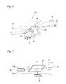
- Fig. 1 is a schematic diagram showing a head-up display 11 of this embodiment.
- the head-up display 11 is configured to mainly have a display device 12 and a combiner 13.
- a cathode-ray tube (CRT) display device a liquid crystal display (LCD), an electroluminescent (EL) display device, a fluorescent display device (for example, seven-segment display), or the like having a small size which can be installed on a dashboard is used.
- the display device 12 is installed on the dashboard, separately from various meters attached to an instrument panel on the driver's seat side of a vehicle.
- the display device 12 functions to display various kinds of information necessary for at least the running of a vehicle, such as an engine rotation speed, a vehicle speed, and a direction signal.
- the display device 12 may be installed so that a display surface is upwardly embedded in a concave part formed on an upper surface of the dashboard. Due to the upward display surface, the display device 12 functions to reflect display light rays (display image) in a direction of a driver from a combiner 13, to be described later, which is affixed to a windshield. The driver can see the display light rays as a virtual image R which is formed on the outside of a windshield 14 simultaneously with a scene on the outside of the windshield. As a result, the driver does not need to frequently move and change the line of sight to the windshield 14 from the meters of the instrument panel, and thus display information is easily confirmed.
- the display device 12 can arbitrarily adjust an emission direction (vertical direction and/or horizontal direction) of the display light rays in accordance with the size and the installation position of the combiner 13. Therefore, the driver and other passengers can securely receive and see the display image (display light rays) on the display device 12 which is reflected by the combiner 13 in their fields of view.
- the combiner 13 is formed of a transparent synthetic resin such as a silicon resin material or an acrylic resin material having a polyethylene terephthalate (PET) film laminated on a front surface, and is directly adhered to the windshield 14 by a method such as sticking, or if necessary, adhered via a material which promotes adhesion to the windshield 14.
- a transparent synthetic resin such as a silicon resin material or an acrylic resin material having a polyethylene terephthalate (PET) film laminated on a front surface
- the combiner 13 is formed into the above-described wedge shape and a predetermined thickness by an optical treatment so that display light rays L1 which are emitted from the display device 12 and reflected by a front surface P of the combiner 13 and display light rays L2 which are reflected by an outer surface T of the windshield overlap to be matched with each other and reach the eye point of the driver in the vehicle as shown in Fig. 2 .
- a display image which is projected to the driver by the display light rays L1 reflected by the front surface P of the combiner 13 and a display image which is projected by the display light rays L2 reflected by the outer surface T of the windshield completely overlap each other, whereby a display image D which reaches the driver does not become a dual image.
- An example of the display image which is seen at this time is shown in Fig. 3.
- Fig. 3 shows the case in which the display of a vehicle speed and the display of a direction signal (display of a left turn signal) on the display device 12 are performed only with normal (ghosting does not occur) display light rays (display image) F1 and F2.
- the combiner 13 is formed to have a wedge-shaped cross-section and have a thickness which is continuously reduced from an upper end to a lower end, it can be mounted on many kinds of vehicles and the formation of the dual image can be avoided.
- the combiner 13 is a sheet-shaped product with a thickness varying as a whole, and can be simply affixed and fixed not only to the windshield, but also to various positions such as the dashboard and the sheet.
- the eye point is set around the driver.
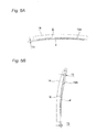
- a head-up display according to a second embodiment of the invention will be described with reference to Fig. 4 , 5A, and 5B .
- constituent parts similar to those shown in Figs. 1 and 3 overlapping descriptions thereof will be omitted.
- a head-up display 11 of this second embodiment is configured to have a display device 12 and a combiner 13A.
- the combiner 13A is formed so that both of a surface opposite to a windshield 14, i.e., a front surface P which forms a first optical surface and a surface which is brought into close contact with the windshield 14, i.e., a rear surface Q which forms a second optical surface form an arc-shaped curved surface in the horizontal direction and the vertical direction, and the curved surface is an aspheric surface.
- the combiner 13A has an aspheric surface, it is possible to suppress the generation of an aberration.
- the combiner 13A has a constant thickness T1 even when being cut along any horizontal plane.
- the combiner 13A has such a form that the thickness thereof gradually varies from a thickness T2 at an upper end to a thickness T3 at a lower end, even when being cut along any vertical plane.
- the front surface P of the combiner 13A is formed into an optimized arc surface (curved surface) by a predetermined optical design so that the driver can see a virtual image which is formed on the outside of the windshield 14 with display light rays (display image) reflected from the front surface P to the driver with a set magnification greater than one.
- the rear surface Q of the combiner 13A is optically designed so that display light rays reflected by the rear surface Q coincide with the display light rays reflected by the front surface P of the combiner 13A in terms of the size and display position. Accordingly, it is possible to prevent a deviation (dual image) between the two display images resulting from a reflective optical path difference between the front surface and the rear surface of the combiner 13A.
- the shapes of the front surface P and the rear surface Q of the combiner 13A can be designed as a polynomial aspheric surface or a free-form surface such as a Zernike polynomial surface in order to more precisely correct a distortion of the display image and set a display distance.
- the aberration of the polynomial aspheric surface or the free-form surface by Zernike polynomials is controlled to alleviate and control the incidence angle of the light rays toward the driver (eyes), whereby it is possible to avoid a dual image from being formed by the reflective optical path difference.
- display light rays (virtual image) reflected by the rear surface Q of the combiner 13A can be allowed to coincide with display light rays (virtual image) reflected by the front surface P at the same viewing angle, and the display image reflected by the combiner 13A can also be displayed slightly back.
- the shape of the rear surface of the combiner 13A is designed as described above, it is possible to prevent the dual image from being formed and see a three-dimensional display image.
- the combiner 13A has a substantially wedge shape so that the thickness thereof is gradually reduced (thinned) from one end (upper end) toward the other end (lower end), and a curvature of the rear surface Q is greater than a curvature of the front surface P.
- the thickness of the combiner 13A is reduced toward the right and left ends and the lower end, except for the upper end part of the combiner 13A. Accordingly, it is possible to improve injection moldability at the time of producing the combiner 13A and reduce the weight of the combiner 13A.
- the combiner 13A of the second embodiment can allow a driver to see a virtual image of display light rays with a set magnification greater than one on the outside of the windshield 14. Accordingly, the driver can rapidly and securely grasp and confirm display information of the display light rays, and it is possible to avoid in advance a difficulty in seeing due to a position deviation between a plurality of display images which are reflected by the front surface and the rear surface of the combiner 13A.
- Fig. 6 is a schematic diagram showing another embodiment of the head-up display 11A of the invention.
- a combiner 13A or 13B is provided inside a windshield 14 (inward direction) to allow a driver (eye point) 16 to see a display image which is emitted from a display device 12 or emission light rays which are emitted from a projector 17 (image projector).
- the respective combiners 13A and 13B are not brought into close contact with the windshield 14, but provided separately from the windshield 14.
- a display device 12 is installed inside the windshield 14 on a dashboard 15 at a predetermined gradient, and displays and emits a display image toward the combiner 13A.
- the combiner 13A reflects the display image toward the driver 18 in the vehicle, and the driver 16 sees a virtual image which is formed on the outside of the windshield 14 through the reflected image.
- the combiner 13A is optimized by the above-described optical design so that the second virtual image of the display light rays which is seen by being reflected by a rear surface of the combiner 13A coincides with the first virtual image of the display light rays which is seen by being reflected by a front surface in terms of the size and display position. Accordingly, it is possible to avoid that the display light rays are positionally deviated from each other (dual image) and seen as in the above-described embodiments.
- the windshield 14 is described as being made of a material having high transparency, a low optical refraction index and low optical reflectivity.
- the combiner 13B reflects a projection image which is emitted from the projector 17 toward the driver. Due to this reflection, the driver sees the image as a virtual image which is formed outside the windshield 14.
- a projection image which is seen by being reflected by a rear surface of the combiner 13B is also a virtual image which is formed outside the windshield 14, and optimization by an optical design is carried out so that the virtual image coincides with a virtual image which is seen by being reflected by a front surface in terms of the size and display position. Accordingly, it is possible to avoid that the projection images are positionally deviated from each other and thus a dual image is seen.
- a light source 18 having strong light energy such as a headlight of an opposed vehicle is positioned at a position on the outside of the windshield 14 deviated from the position at which the virtual image of the display light rays is formed by the combiner 13A.
- light rays which pass through the windshield 14 from the light source 18 and enter the vehicle are reflected by the rear surface of the combiner 13A, and then reflected by an inner surface of the windshield 14 as shown in the drawing.
- the combiner 13A is disposed to project light rays to the position deviated from the point of view (viewpoint) of the driver 16, it is possible to prevent the formation of a ghost image by the light source 18.
- the combiner 13A or the combiner 13B when display images or projection images which are emitted from the display device 12 or the projector 17 are reflected using the combiner 13A or the combiner 13B, it is possible to see these virtual images on the outside of the windshield 14 without significantly changing the line of sight.
- the combiners 13A and 13B are formed on the basis of an optical design of a polynomial aspheric surface or a free-form surface such as a Zernike polynomial surface, the virtual images of the display images which are seen by being reflected by the front surfaces of the combiners 13A and 13B can be formed at a predetermined position on the outside of the windshield with a set magnification greater than one, so as not to form a dual image.
- the first virtual image of the display images or the projection images which are seen by being reflected by the front surfaces of the combiners 13A and 13B is allowed to coincide with the second virtual image which is seen by being reflected by the rear surfaces of the combiners 13A and 13B in terms of the size and position, it is possible for the driver to clearly and rapidly see a magnified high-quality display image or projection image.
- the second virtual image which is seen by being reflected by the rear surfaces of the combiners 13A and 13B is formed behind the first virtual image which is seen by being reflected by the front surfaces, it is possible to give a three-dimensional effect to the display image or the projection image.
- the projection images not only from the display device 12 on the dashboard 15 but also from the projector 17 installed on a ceiling or the like of the vehicle can be reflected by the combiner 13B and seen by the driver as a virtual image magnified with a magnification greater than one.
- the respective combiners 13A and 13B are installed at a position separated from the windshield 14 as described above. In this case, it is also possible to clearly see the display light rays and the projection light rays with a magnification greater than one while preventing the display light rays and the projection light rays (projection image) from forming a dual image through the above-described optimization of the optical design for the combiners 13A and 13B.
- the combiners 13A and 13B can be subjected to the correction of a distortion of the display image and the setting of the display distance in the polynomial aspheric surface or the free-form surface such as a Zernike polynomial surface.
- the head-up display 11 of this embodiment includes the display device 12 which emits display light rays and the combiner 13 which has a rear surface brought into contact with the inner surface of the windshield 14 of a vehicle, and reflects the display light rays emitted from the display device 12 by the front surface toward a driver in the vehicle, and in the combiner 13, the front surface forms the first arc-shaped optical surface P to receive the display light rays reflected toward the driver to thereby see a first virtual image R of the display information with a set magnification greater than one on the outside of the windshield 14, and the rear surface forms the second arc-shaped optical surface Q to receive the display light rays reflected toward the driver to thereby see a second virtual image S which coincides with the first virtual image R in terms of the size and position on the outside of the windshield 14.
- the display surface of the display device 12 longer than a focal length is placed on the first optical surface P through a lens action of the combiner 13, and thus the magnification by the combiner 13 is greater than one. Therefore, the eyes of the driver see the display light rays emitted from the display device 12 as a first virtual image R, and the driver can accurately and rapidly grasp and confirm the content of the display information by looking at the magnified display light rays. Since the second optical surface Q forms a second virtual image S which coincides with the first virtual image R in terms of the size and position on the outside of the windshield 14, it is possible to avoid the formation of a dual image in advance.
- first optical surface P and the second optical surface Q are arc-shaped optical surfaces so that the second virtual image S can be seen to be positioned behind the first virtual image R, it is possible for the eyes of the driver which see both of the virtual images R and S to recognize the display light rays (display image) as a three-dimensional image.
- the display light rays which are reflected from the front surface and the rear surface of the combiner 13 having different curvatures can be seen as display light rays having a three-dimensional effect, while being prevented from forming a dual image.
- the combiner 13 is formed so that the thickness from the upper end to the lower end opposed to the upper end is thinned, it is possible to securely prevent the display light rays which are reflected by the front surface of the combiner 13 and seen by the driver and the display light rays which are reflected by the rear surface of the combiner 13 and seen by the driver from being positionally deviated from each other and from forming a dual image.
Landscapes
- Engineering & Computer Science (AREA)
- Physics & Mathematics (AREA)
- Chemical & Material Sciences (AREA)
- Combustion & Propulsion (AREA)
- Transportation (AREA)
- Mechanical Engineering (AREA)
- General Physics & Mathematics (AREA)
- Optics & Photonics (AREA)
- Instrument Panels (AREA)
Abstract
Description
- The present invention is related to a head-up display having a combiner which reflects light rays emitted from a display device toward a driver.
- Various head-up displays have been proposed to allow a driver of a vehicle to see various kinds of driving information (for example, see PTL 1). For example, as shown in
Fig. 7 , the head-up displays reflect display light rays (display image) emitted from adisplay device 22 installed in a lower part of awindshield 21 toward a driver by a thin plate-shaped combiner 23 (a reflection member) formed on a surface of thewindshield 21. Accordingly, the driver is allowed to be able to recognize display light rays 24 (display image) which forms a virtual image overlapping a scene in front of the windshield through the windshield. - According to the head-up display, the driver can significantly reduce the number of movements of line of sight, that have been conventionally performed, which is occurred by alternately and repeatedly looking at the displays of various meters embedded in a front surface of an instrument panel and looking at scenes and traffic situations ahead through the windshield. That is, it is possible to visually confirm and recognize on the windshield the displays of the various meters together with the scenes and traffic situations ahead through the windshield, without moving the line of sight and changing the focus of eyes significantly. Therefore, it is possible to secure steering stability of the vehicle.
- However, when the display image is allowed to be formed and seen as a virtual image on the outside of the windshield, the driver sees a double image in which a position deviation occurs between
display images Fig. 8 shows the case in which display light rays (ghost image) G1 and G2 positionally deviated with respect to normal display light rays (display image) F1 and F2 for the display of a vehicle speed and the display of a direction signal (display of a left turn signal) on adisplay device 12 are seen. Meanwhile, in order to prevent the occurrence of such a double image, a method is considered which includes forming an AR coating (antireflection film) on a rear surface of acombiner 23 and suppressing reflected light rays (reflected image) from the rear surface of thecombiner 23 to more clearly see reflected light rays from a front surface of the combiner than the reflected light rays from the rear surface. However, this method is not practical because an antireflection film treatment is required to be performed on thecombiner 23 and this leads to an increase in the total cost of the head-up display. - With respect to this, a head-up display is proposed in which a front glass having a three-layer structure which functions as a combiner is used to allow display images which are reflected by an inner surface and an outer surface of the front glass and reach an observer to overlap each other to thereby form a single image (for example, see PTL 2). In the head-up display, principal surfaces on both sides of the front glass are not parallel to each other in a selected area. The information display entering the non-parallel principal surface of the front glass is configured so that directions of light rays which are reflected by the inner surface and light rays which approach the glass and are reflected by the outer surface are emitted from the inner surface are determined along the same line in a range of a driver's eyes. Accordingly, it is possible to reduce the frequency of the formation of a double image which is formed when the laminated front glass is used as a combiner of the display device.
-
- [PTL 1]
JP-A-2003-039983 - [PTL 2]
JP-A-07-195959 - The above-described head-up display disclosed in PTL 2 has the following problems to be solved. That is, in order to realize the head-up display, the front glass itself employs a three-layer structure in which an intermediate layer, of which the thickness from the top to the bottom varies into a tapered shape, is sandwiched between two sheets of glass. Therefore, since the head-up display becomes a special order product, the cost increases and there is an inconvenience in which the head-up display cannot be employed in vehicles having a general front glass.
- It is therefore one advantageous aspect of the present invention to provide a head-up display which prevents virtual images of display images, which are seen by being reflected by a front surface and a rear surface of a combiner, from forming a dual image to clearly see the display image, and can be configured and used at a low cost by simply attaching the combiner to a general front glass.
- The head-up display according to the invention has the following characteristics (1) to (6) in order to achieve the above-described object.
- (1) A head-up display comprising:
- a display device that emits display light rays; and
- a combiner that has a rear surface brought into contact with an inner surface of a windshield of a vehicle, and reflects the display light rays emitted from the display device by a front surface of the combiner toward a driver in the vehicle,
- (2) The head-up display according to the above (1), wherein
the first optical surface and the second optical surface are arc-shaped optical surfaces so that the second virtual image is seen to be positioned behind the first virtual image. - (3) The head-up display according to the above (1) or (2), wherein
a curvature of the second optical surface of the combiner is greater than a curvature of the first optical surface of the combiner. - (4) The head-up display according to the above (1) or (2), wherein
a thickness of the combiner becomes thinner from one end to the other end. - (5) A head-up display comprising:
- a display device that emits display light rays; and
- a combiner that has a rear surface brought into contact with an inner surface of a windshield of a vehicle, and reflects the display light rays emitted from the display device by a front surface of the combiner toward a driver in the vehicle,
- (6) A head-up display comprising:
- a display device that emits display light rays; and
- a combiner that is disposed separately from an inner surface of a windshield of a vehicle, and reflects the display light rays emitted from the display device by a front surface of the combiner toward a driver in the vehicle,
- According to the head-up display according to (1), the first optical surface virtually forms an optical surface on which a display surface of the display device longer than a focal length is placed through a lens action of the combiner, and thus the magnification by the combiner is greater than one. Therefore, the eyes of the driver see the display light rays emitted from the display device as a magnified first virtual image. Therefore, the driver can accurately and rapidly grasp and confirm the content of the display information by looking at the magnified display light rays. In addition, since the second optical surface forms a second virtual image which coincides with the first virtual image in terms of the size and position on the outside of the windshield, it is possible to avoid in advance the formation of a dual image due to a position deviation or the like between the relative positions of the first virtual image and the second virtual image.
In addition, according to the head-up display according to (2), since the second virtual image is formed behind the first virtual image so that the positions of the first virtual image and the second virtual image are deviated from each other, the eyes of the driver which see both of the virtual images can recognize the display light rays (display image) as a three-dimensional image.
In addition, according to the head-up display according to (3), the display light rays which are reflected toward the driver from the front surface and the rear surface of the combiner having different curvatures can be seen as display light rays having a three-dimensional effect, while being prevented from forming a dual image.
In addition, according to the head-up display according to (4), it is possible to securely prevent the display light rays which are reflected by the front surface of the combiner and seen by the driver and the display light rays which are reflected by the rear surface of the combiner and seen by the driver from being positionally deviated from each other and from forming a dual image.
In addition, according to the head-up display according to (5), the combiner has such a thickness shape that the display light rays which are emitted from the display device and reflected by the front surface of the combiner and the display light rays which are reflected by the outer surface of the windshield overlap each other and reach the eyes of the driver, and thus a display image which is projected by the display light rays reflected by the front surface of the combiner and a display image which is projected by the display light rays reflected by the outer surface of the windshield overlap each other without a deviation, whereby it is possible to avoid that the display image which is seen by the driver becomes a dual image.
In addition, according to the head-up display according to (6), the driver can accurately and rapidly grasp and confirm the content of the display information by looking at the magnified display light rays. In addition, since the second optical surface forms a second virtual image which coincides with the first virtual image in terms of the size and position on the outside of the windshield, it is possible to avoid in advance the formation of a dual image due to a position deviation or the like between the relative positions of the first virtual image and the second virtual image. - According to the invention, virtual images of display images which are seen by being reflected by a front surface and a rear surface of a combiner are prevented from forming a dual image, and the display image can be clearly seen without significantly changing the line of sight movement, whereby it is possible to accurately and rapidly grasp the content of the display information.
- The invention has been briefly described as above. The invention will be further clarified in detail when reading through embodiments for carrying out the invention to be described below with reference to the accompanying drawings.
-
-
Fig. 1 is a schematic diagram showing a head-up display according to a first embodiment of the invention. -
Fig. 2 is an explanatory diagram showing an action of avoiding the formation of a dual image by the combiner shown inFig. 1 . -
Fig. 3 is an explanatory diagram showing a display image which is seen by the head-up display of the invention. -
Fig. 4 is a schematic diagram showing a head-up display according to a second embodiment of the invention. -
Figs. 5A and 5B are cross-sectional views of the combiner shown inFig. 4 .Fig. 5A is a transverse sectional view cut along the horizontal plane passing through the center of the combiner, andFig. 5B is a longitudinal sectional view cut along the vertical plane passing through the center of the combiner. -
Fig. 6 is a schematic diagram showing a head-up display according to another embodiment of the invention. -
Fig. 7 is a schematic diagram showing a conventional head-up display. -
Fig. 8 is an explanatory diagram showing a display image which is seen by a conventional head-up display. - Hereinafter, a head-up display according to a first embodiment of the invention will be described with reference to
Figs. 1 to 3 .Fig. 1 is a schematic diagram showing a head-updisplay 11 of this embodiment. The head-updisplay 11 is configured to mainly have adisplay device 12 and acombiner 13. - Among them, as the
display device 12, a cathode-ray tube (CRT) display device, a liquid crystal display (LCD), an electroluminescent (EL) display device, a fluorescent display device (for example, seven-segment display), or the like having a small size which can be installed on a dashboard is used. Thedisplay device 12 is installed on the dashboard, separately from various meters attached to an instrument panel on the driver's seat side of a vehicle. Thedisplay device 12 functions to display various kinds of information necessary for at least the running of a vehicle, such as an engine rotation speed, a vehicle speed, and a direction signal. - The
display device 12 may be installed so that a display surface is upwardly embedded in a concave part formed on an upper surface of the dashboard. Due to the upward display surface, thedisplay device 12 functions to reflect display light rays (display image) in a direction of a driver from acombiner 13, to be described later, which is affixed to a windshield. The driver can see the display light rays as a virtual image R which is formed on the outside of awindshield 14 simultaneously with a scene on the outside of the windshield. As a result, the driver does not need to frequently move and change the line of sight to thewindshield 14 from the meters of the instrument panel, and thus display information is easily confirmed. - In addition, the
display device 12 can arbitrarily adjust an emission direction (vertical direction and/or horizontal direction) of the display light rays in accordance with the size and the installation position of thecombiner 13. Therefore, the driver and other passengers can securely receive and see the display image (display light rays) on thedisplay device 12 which is reflected by thecombiner 13 in their fields of view. - The
combiner 13 is formed of a transparent synthetic resin such as a silicon resin material or an acrylic resin material having a polyethylene terephthalate (PET) film laminated on a front surface, and is directly adhered to thewindshield 14 by a method such as sticking, or if necessary, adhered via a material which promotes adhesion to thewindshield 14. - In the head-up
display 11 having such a configuration, thecombiner 13 is formed into the above-described wedge shape and a predetermined thickness by an optical treatment so that display light rays L1 which are emitted from thedisplay device 12 and reflected by a front surface P of thecombiner 13 and display light rays L2 which are reflected by an outer surface T of the windshield overlap to be matched with each other and reach the eye point of the driver in the vehicle as shown inFig. 2 . In other words, a display image which is projected to the driver by the display light rays L1 reflected by the front surface P of thecombiner 13 and a display image which is projected by the display light rays L2 reflected by the outer surface T of the windshield completely overlap each other, whereby a display image D which reaches the driver does not become a dual image. An example of the display image which is seen at this time is shown inFig. 3. Fig. 3 shows the case in which the display of a vehicle speed and the display of a direction signal (display of a left turn signal) on thedisplay device 12 are performed only with normal (ghosting does not occur) display light rays (display image) F1 and F2. - In addition, since the
combiner 13 is formed to have a wedge-shaped cross-section and have a thickness which is continuously reduced from an upper end to a lower end, it can be mounted on many kinds of vehicles and the formation of the dual image can be avoided. Thecombiner 13 is a sheet-shaped product with a thickness varying as a whole, and can be simply affixed and fixed not only to the windshield, but also to various positions such as the dashboard and the sheet. In the above description, the case has been described in which the eye point is set around the driver. However, it is possible to clearly see various kinds of information in the vehicle by setting an angle which corresponds to a passenger of a passenger's seat and other passengers. - Next, a head-up display according to a second embodiment of the invention will be described with reference to
Fig. 4 ,5A, and 5B . Regarding constituent parts similar to those shown inFigs. 1 and3 , overlapping descriptions thereof will be omitted. - As shown in
Fig. 4 , a head-updisplay 11 of this second embodiment is configured to have adisplay device 12 and acombiner 13A. As shown inFigs. 5A and 5B , thecombiner 13A is formed so that both of a surface opposite to awindshield 14, i.e., a front surface P which forms a first optical surface and a surface which is brought into close contact with thewindshield 14, i.e., a rear surface Q which forms a second optical surface form an arc-shaped curved surface in the horizontal direction and the vertical direction, and the curved surface is an aspheric surface. When thecombiner 13A has an aspheric surface, it is possible to suppress the generation of an aberration. - As shown in
Fig. 5A , thecombiner 13A has a constant thickness T1 even when being cut along any horizontal plane. On the other hand, as shown inFig. 5B , thecombiner 13A has such a form that the thickness thereof gradually varies from a thickness T2 at an upper end to a thickness T3 at a lower end, even when being cut along any vertical plane. - In addition, the front surface P of the
combiner 13A is formed into an optimized arc surface (curved surface) by a predetermined optical design so that the driver can see a virtual image which is formed on the outside of thewindshield 14 with display light rays (display image) reflected from the front surface P to the driver with a set magnification greater than one. The rear surface Q of thecombiner 13A is optically designed so that display light rays reflected by the rear surface Q coincide with the display light rays reflected by the front surface P of thecombiner 13A in terms of the size and display position. Accordingly, it is possible to prevent a deviation (dual image) between the two display images resulting from a reflective optical path difference between the front surface and the rear surface of thecombiner 13A. - The shapes of the front surface P and the rear surface Q of the
combiner 13A can be designed as a polynomial aspheric surface or a free-form surface such as a Zernike polynomial surface in order to more precisely correct a distortion of the display image and set a display distance. In thecombiner 13A, the aberration of the polynomial aspheric surface or the free-form surface by Zernike polynomials is controlled to alleviate and control the incidence angle of the light rays toward the driver (eyes), whereby it is possible to avoid a dual image from being formed by the reflective optical path difference. - In addition, by a design method similar to the design of the polynomial aspheric surface or the free-form surface such as a Zernike polynomial surface, display light rays (virtual image) reflected by the rear surface Q of the
combiner 13A can be allowed to coincide with display light rays (virtual image) reflected by the front surface P at the same viewing angle, and the display image reflected by thecombiner 13A can also be displayed slightly back. When the shape of the rear surface of thecombiner 13A is designed as described above, it is possible to prevent the dual image from being formed and see a three-dimensional display image. - Furthermore, the
combiner 13A has a substantially wedge shape so that the thickness thereof is gradually reduced (thinned) from one end (upper end) toward the other end (lower end), and a curvature of the rear surface Q is greater than a curvature of the front surface P. InFigs. 5A and 5B , the thickness of thecombiner 13A is reduced toward the right and left ends and the lower end, except for the upper end part of thecombiner 13A. Accordingly, it is possible to improve injection moldability at the time of producing thecombiner 13A and reduce the weight of thecombiner 13A. - As described above, by virtue of a predetermined optical design, the
combiner 13A of the second embodiment can allow a driver to see a virtual image of display light rays with a set magnification greater than one on the outside of thewindshield 14. Accordingly, the driver can rapidly and securely grasp and confirm display information of the display light rays, and it is possible to avoid in advance a difficulty in seeing due to a position deviation between a plurality of display images which are reflected by the front surface and the rear surface of thecombiner 13A. Meanwhile, when a second virtual image S of the display light rays which are reflected by the rear surface Q of thecombiner 13A is formed slightly behind a first virtual image R of the display image which is reflected by the front surface P of thecombiner 13A, it is possible to see a three-dimensional display image without making the display image indistinct due to the formation of a dual image. -
Fig. 6 is a schematic diagram showing another embodiment of the head-updisplay 11A of the invention. In this embodiment, acombiner display device 12 or emission light rays which are emitted from a projector 17 (image projector). Here, therespective combiners windshield 14, but provided separately from thewindshield 14. Adisplay device 12 is installed inside thewindshield 14 on adashboard 15 at a predetermined gradient, and displays and emits a display image toward thecombiner 13A. - The
combiner 13A reflects the display image toward thedriver 18 in the vehicle, and thedriver 16 sees a virtual image which is formed on the outside of thewindshield 14 through the reflected image. Thecombiner 13A is optimized by the above-described optical design so that the second virtual image of the display light rays which is seen by being reflected by a rear surface of thecombiner 13A coincides with the first virtual image of the display light rays which is seen by being reflected by a front surface in terms of the size and display position. Accordingly, it is possible to avoid that the display light rays are positionally deviated from each other (dual image) and seen as in the above-described embodiments. Here, for ease of description, thewindshield 14 is described as being made of a material having high transparency, a low optical refraction index and low optical reflectivity. - The
combiner 13B reflects a projection image which is emitted from theprojector 17 toward the driver. Due to this reflection, the driver sees the image as a virtual image which is formed outside thewindshield 14. In this case, a projection image which is seen by being reflected by a rear surface of thecombiner 13B is also a virtual image which is formed outside thewindshield 14, and optimization by an optical design is carried out so that the virtual image coincides with a virtual image which is seen by being reflected by a front surface in terms of the size and display position. Accordingly, it is possible to avoid that the projection images are positionally deviated from each other and thus a dual image is seen. - In addition, in some cases, a
light source 18 having strong light energy such as a headlight of an opposed vehicle is positioned at a position on the outside of thewindshield 14 deviated from the position at which the virtual image of the display light rays is formed by thecombiner 13A. In this case, light rays which pass through thewindshield 14 from thelight source 18 and enter the vehicle are reflected by the rear surface of thecombiner 13A, and then reflected by an inner surface of thewindshield 14 as shown in the drawing. When thecombiner 13A is disposed to project light rays to the position deviated from the point of view (viewpoint) of thedriver 16, it is possible to prevent the formation of a ghost image by thelight source 18. - As described above, when display images or projection images which are emitted from the
display device 12 or theprojector 17 are reflected using thecombiner 13A or thecombiner 13B, it is possible to see these virtual images on the outside of thewindshield 14 without significantly changing the line of sight. In addition, when thecombiners combiners - In addition, when the first virtual image of the display images or the projection images which are seen by being reflected by the front surfaces of the
combiners combiners combiners - In this manner, the projection images not only from the
display device 12 on thedashboard 15 but also from theprojector 17 installed on a ceiling or the like of the vehicle can be reflected by thecombiner 13B and seen by the driver as a virtual image magnified with a magnification greater than one. Therespective combiners windshield 14 as described above. In this case, it is also possible to clearly see the display light rays and the projection light rays with a magnification greater than one while preventing the display light rays and the projection light rays (projection image) from forming a dual image through the above-described optimization of the optical design for thecombiners combiners - As described above, the head-up
display 11 of this embodiment includes thedisplay device 12 which emits display light rays and thecombiner 13 which has a rear surface brought into contact with the inner surface of thewindshield 14 of a vehicle, and reflects the display light rays emitted from thedisplay device 12 by the front surface toward a driver in the vehicle, and in thecombiner 13, the front surface forms the first arc-shaped optical surface P to receive the display light rays reflected toward the driver to thereby see a first virtual image R of the display information with a set magnification greater than one on the outside of thewindshield 14, and the rear surface forms the second arc-shaped optical surface Q to receive the display light rays reflected toward the driver to thereby see a second virtual image S which coincides with the first virtual image R in terms of the size and position on the outside of thewindshield 14. - Accordingly, the display surface of the
display device 12 longer than a focal length is placed on the first optical surface P through a lens action of thecombiner 13, and thus the magnification by thecombiner 13 is greater than one. Therefore, the eyes of the driver see the display light rays emitted from thedisplay device 12 as a first virtual image R, and the driver can accurately and rapidly grasp and confirm the content of the display information by looking at the magnified display light rays. Since the second optical surface Q forms a second virtual image S which coincides with the first virtual image R in terms of the size and position on the outside of thewindshield 14, it is possible to avoid the formation of a dual image in advance. - In addition, since the first optical surface P and the second optical surface Q are arc-shaped optical surfaces so that the second virtual image S can be seen to be positioned behind the first virtual image R, it is possible for the eyes of the driver which see both of the virtual images R and S to recognize the display light rays (display image) as a three-dimensional image.
- In addition, since the curvature of the second optical surface Q is greater than the curvature of the first optical surface P in the
combiner 13, the display light rays which are reflected from the front surface and the rear surface of thecombiner 13 having different curvatures can be seen as display light rays having a three-dimensional effect, while being prevented from forming a dual image. - Furthermore, since the
combiner 13 is formed so that the thickness from the upper end to the lower end opposed to the upper end is thinned, it is possible to securely prevent the display light rays which are reflected by the front surface of thecombiner 13 and seen by the driver and the display light rays which are reflected by the rear surface of thecombiner 13 and seen by the driver from being positionally deviated from each other and from forming a dual image. - The invention has been described in detail with reference to the particular embodiment, but it is obvious for those skilled in the art that various changes and modifications can be added without departing from the spirit and scope of the invention.
- Priority is claimed on Japanese Patent Application No.
2010-204687, filed September 13, 2010 - According to the invention, there are advantages in that virtual images of display images which are seen by being reflected by the front surface and the rear surface of the combiner are prevented from forming a dual image, and the display image can be clearly seen without significantly changing the line of sight movement, whereby it is possible to accurately and rapidly grasp the content of the display information.
-
- 11, 11A: HEAD-UP DISPLAY
- 12: DISPLAY DEVICE
- 13, 13A, 13B: COMBINER
- 14: WINDSHIELD
- 15: DASHBOARD
- 17: PROJECTOR
- 18: LIGHT SOURCE
- P: FRONT SURFACE (FIRST OPTICAL SURFACE)
- Q: REAR SURFACE (SECOND OPTICAL SURFACE)
- R: FIRST VIRTUAL IMAGE
- S: SECOND VIRTUAL IMAGE
Claims (6)
- A head-up display comprising:a display device that emits display light rays; anda combiner that has a rear surface brought into contact with an inner surface of a windshield of a vehicle, and reflects the display light rays emitted from the display device by a front surface of the combiner toward a driver in the vehicle,wherein the front surface of the combiner forms a first arc-shaped optical surface which receives and reflects the display light rays emitted from the display device toward the driver so that the driver sees a first virtual image of the display light rays with a set magnification greater than 1 on the outside of the windshield, and the rear surface forms a second arc-shaped optical surface which receives and reflects the display light rays emitted from the display device toward the driver so that the driver sees a second virtual image which coincides with the first virtual image in terms of the size and position on an outside of the windshield.
- The head-up display according to claim 1, wherein
the first optical surface and the second optical surface are arc-shaped optical surfaces so that the second virtual image is seen to be positioned behind the first virtual image. - The head-up display according to claim 1 or 2, wherein
a curvature of the second optical surface of the combiner is greater than a curvature of the first optical surface of the combiner. - The head-up display according to claim 1 or 2, wherein
a thickness of the combiner becomes thinner from one end to the other end. - A head-up display comprising:a display device that emits display light rays; anda combiner that has a rear surface brought into contact with an inner surface of a windshield of a vehicle, and reflects the display light rays emitted from the display device by a front surface of the combiner toward a driver in the vehicle,wherein the combiner has a cross-section formed into a wedge shape, and a thickness of the cross-section continuously becomes thinner from one end to the other end.
- A head-up display comprising:a display device that emits display light rays; anda combiner that is disposed separately from an inner surface of a windshield of a vehicle, and reflects the display light rays emitted from the display device by a front surface of the combiner toward a driver in the vehicle,wherein the front surface of the combiner forms a first arc-shaped optical surface to receive and reflect the display light rays emitted from the display device toward the driver so that the driver sees a first virtual image of the display light rays with a set magnification greater than 1 on an outside of the windshield, and the rear surface of the combiner forms a second arc-shaped optical surface to receive and reflect the display light rays emitted from the display device toward the driver so that the driver sees a second virtual image which coincides with the first virtual image in terms of the size and position on the outside of the windshield.
Applications Claiming Priority (2)
| Application Number | Priority Date | Filing Date | Title |
|---|---|---|---|
| JP2010204687A JP5802002B2 (en) | 2010-09-13 | 2010-09-13 | Head-up display |
| PCT/JP2011/070647 WO2012036099A1 (en) | 2010-09-13 | 2011-09-09 | Head up display |
Publications (3)
| Publication Number | Publication Date |
|---|---|
| EP2618203A1 true EP2618203A1 (en) | 2013-07-24 |
| EP2618203A4 EP2618203A4 (en) | 2018-03-14 |
| EP2618203B1 EP2618203B1 (en) | 2020-11-04 |
Family
ID=45831562
Family Applications (1)
| Application Number | Title | Priority Date | Filing Date |
|---|---|---|---|
| EP11825102.4A Not-in-force EP2618203B1 (en) | 2010-09-13 | 2011-09-09 | Head up display |
Country Status (4)
| Country | Link |
|---|---|
| US (1) | US9052504B2 (en) |
| EP (1) | EP2618203B1 (en) |
| JP (1) | JP5802002B2 (en) |
| WO (1) | WO2012036099A1 (en) |
Cited By (6)
| Publication number | Priority date | Publication date | Assignee | Title |
|---|---|---|---|---|
| CN104085349A (en) * | 2014-07-25 | 2014-10-08 | 大连引航光电信息技术有限公司 | Head-up display device |
| EP2865555A4 (en) * | 2012-06-25 | 2015-06-24 | Toyota Motor Co Ltd | INFORMATION DISPLAY DEVICE FOR VEHICLE |
| GB2534151A (en) * | 2015-01-14 | 2016-07-20 | Jaguar Land Rover Ltd | Head-up display apparatus |
| EP3076221A1 (en) * | 2015-04-02 | 2016-10-05 | Continental Automotive GmbH | Hybrid head-up display |
| CN107436623A (en) * | 2016-05-28 | 2017-12-05 | 深圳富泰宏精密工业有限公司 | Protect covering device and the display control method applied to the protection covering device |
| EP3422080A4 (en) * | 2016-02-25 | 2019-02-06 | Konica Minolta, Inc. | SCREEN AND DISPLAY DEVICE HIGH HEAD |
Families Citing this family (29)
| Publication number | Priority date | Publication date | Assignee | Title |
|---|---|---|---|---|
| JP5813243B2 (en) * | 2012-09-27 | 2015-11-17 | パイオニア株式会社 | Display device |
| JP5831434B2 (en) * | 2012-12-07 | 2015-12-09 | 株式会社デンソー | Head-up display device |
| JP6549817B2 (en) * | 2013-04-11 | 2019-07-24 | 矢崎総業株式会社 | Combiner |
| JP6205595B2 (en) * | 2013-04-23 | 2017-10-04 | カルソニックカンセイ株式会社 | Vehicle display device |
| US20150131158A1 (en) * | 2013-11-13 | 2015-05-14 | E-Lead Electronic Co., Ltd. | Vehicle head-up display device for preventing ghost images |
| BR112016012378B1 (en) * | 2013-12-12 | 2021-09-28 | Saint-Gobain Glass France | THERMOPLASTIC FILM FOR A LAMINATED GLASS SHEET HAVING A CONTINUOUS NON-LINEAR WEDGE INSERT IN THE VERTICAL DIRECTION IN SOME SECTIONS |
| MX2017007407A (en) | 2014-12-08 | 2017-11-06 | Saint Gobain | Laminated glass having reduced thickness for a head-up display (hud). |
| US9658450B2 (en) * | 2015-05-05 | 2017-05-23 | Honda Motor Co., Ltd. | Vehicle heads-up display device |
| CN106489095B (en) | 2015-06-11 | 2019-07-16 | 法国圣戈班玻璃厂 | For contacting the projection arrangement of simulation head-up display (HUD) |
| CA2988210C (en) | 2015-06-11 | 2020-09-15 | Saint-Gobain Glass France | Projection arrangement for a head-up display (hud) |
| JP6308172B2 (en) * | 2015-06-11 | 2018-04-11 | 株式会社デンソー | Display device |
| JP6516223B2 (en) * | 2015-06-30 | 2019-05-22 | パナソニックIpマネジメント株式会社 | Display device |
| JP6569898B2 (en) * | 2015-06-30 | 2019-09-04 | パナソニックIpマネジメント株式会社 | Display device and display method |
| CN104950447A (en) * | 2015-07-13 | 2015-09-30 | 京东方科技集团股份有限公司 | Head up display device and vehicle |
| WO2017038043A1 (en) | 2015-08-31 | 2017-03-09 | パナソニックIpマネジメント株式会社 | Head-up display |
| JP6726674B2 (en) * | 2015-10-15 | 2020-07-22 | マクセル株式会社 | Information display device |
| US10175481B2 (en) * | 2016-01-29 | 2019-01-08 | Panasonic Automotive Systems Company Of America, Division Of Panasonic Corporation Of North America | Head up display with total internal reflection optical element |
| US10335986B2 (en) | 2016-03-07 | 2019-07-02 | Panasonic Intellectual Property Management Co., Ltd. | Reflective display device, injection mold, and method for manufacturing reflective display device |
| JP6612989B2 (en) | 2016-03-17 | 2019-11-27 | サン−ゴバン グラス フランス | Composite pane with conductive coating for head-up display |
| DE102016212527B4 (en) | 2016-07-08 | 2019-08-08 | Magna Mirrors Holding Gmbh | Blink unit for an exterior mirror |
| JP6365646B2 (en) * | 2016-12-06 | 2018-08-01 | 株式会社Jvcケンウッド | Display device and display method |
| CN106681004A (en) * | 2017-02-14 | 2017-05-17 | 深圳前海智云谷科技有限公司 | Embedded head-up display device |
| JP6593462B2 (en) * | 2018-01-12 | 2019-10-23 | 株式会社Jvcケンウッド | Virtual image display device |
| JP6593494B1 (en) * | 2018-06-08 | 2019-10-23 | 株式会社Jvcケンウッド | Virtual image display device |
| WO2019138627A1 (en) * | 2018-01-12 | 2019-07-18 | 株式会社Jvcケンウッド | Virtual image display device |
| US10885819B1 (en) * | 2019-08-02 | 2021-01-05 | Harman International Industries, Incorporated | In-vehicle augmented reality system |
| CN113671698B (en) * | 2020-05-15 | 2022-07-29 | 华为技术有限公司 | Head-up display system and image display method based on head-up display system |
| DE202021004087U1 (en) * | 2020-06-18 | 2022-08-08 | Saint-Gobain Glass France | Vehicle with a head-up display |
| JP7481310B2 (en) * | 2021-10-29 | 2024-05-10 | 矢崎総業株式会社 | Vehicle display device |
Family Cites Families (12)
| Publication number | Priority date | Publication date | Assignee | Title |
|---|---|---|---|---|
| US5812332A (en) | 1989-09-28 | 1998-09-22 | Ppg Industries, Inc. | Windshield for head-up display system |
| US5013134A (en) * | 1989-09-28 | 1991-05-07 | Hughes Aircraft Company | Ghost-free automotive head-up display employing a wedged windshield |
| IT1256343B (en) | 1991-08-20 | 1995-12-01 | Ppg Industries Inc | AUTOMOTIVE WINDSHIELD FOR A STRAIGHT HEAD DISPLAY SYSTEM |
| JP3573765B2 (en) * | 1993-03-18 | 2004-10-06 | カルソニックカンセイ株式会社 | Vehicle head-up display device |
| JPH09304728A (en) * | 1996-05-15 | 1997-11-28 | Sony Corp | Optical vision device |
| US6359737B1 (en) * | 2000-07-28 | 2002-03-19 | Generals Motors Corporation | Combined head-up display |
| JP4577638B2 (en) | 2001-07-30 | 2010-11-10 | 日本精機株式会社 | Vehicle display device |
| DE60133052T2 (en) | 2001-07-30 | 2009-04-30 | Nippon Seiki Co. Ltd., Nagaoka | VEHICLE DISPLAY DEVICE |
| WO2004023195A2 (en) | 2002-09-03 | 2004-03-18 | E Ink Corporation | Electro-optic displays |
| JP2005156678A (en) * | 2003-11-21 | 2005-06-16 | Nippon Seiki Co Ltd | Combiner and head-up display using the combiner |
| JP4914799B2 (en) * | 2006-11-13 | 2012-04-11 | 矢崎総業株式会社 | Windshield and head-up display unit |
| CN101888927B (en) * | 2007-12-07 | 2013-05-29 | 法国圣戈班玻璃厂 | Curved vehicle windshield made from laminated glass |
-
2010
- 2010-09-13 JP JP2010204687A patent/JP5802002B2/en active Active
-
2011
- 2011-09-09 EP EP11825102.4A patent/EP2618203B1/en not_active Not-in-force
- 2011-09-09 WO PCT/JP2011/070647 patent/WO2012036099A1/en not_active Ceased
-
2013
- 2013-03-12 US US13/796,971 patent/US9052504B2/en active Active
Non-Patent Citations (1)
| Title |
|---|
| See references of WO2012036099A1 * |
Cited By (8)
| Publication number | Priority date | Publication date | Assignee | Title |
|---|---|---|---|---|
| EP2865555A4 (en) * | 2012-06-25 | 2015-06-24 | Toyota Motor Co Ltd | INFORMATION DISPLAY DEVICE FOR VEHICLE |
| CN104085349A (en) * | 2014-07-25 | 2014-10-08 | 大连引航光电信息技术有限公司 | Head-up display device |
| CN104085349B (en) * | 2014-07-25 | 2016-05-04 | 江西派路特科技有限公司 | Head-up display |
| GB2534151A (en) * | 2015-01-14 | 2016-07-20 | Jaguar Land Rover Ltd | Head-up display apparatus |
| US10162175B2 (en) | 2015-01-14 | 2018-12-25 | Jaguar Land Rover Limited | Dual head-up display apparatus |
| EP3076221A1 (en) * | 2015-04-02 | 2016-10-05 | Continental Automotive GmbH | Hybrid head-up display |
| EP3422080A4 (en) * | 2016-02-25 | 2019-02-06 | Konica Minolta, Inc. | SCREEN AND DISPLAY DEVICE HIGH HEAD |
| CN107436623A (en) * | 2016-05-28 | 2017-12-05 | 深圳富泰宏精密工业有限公司 | Protect covering device and the display control method applied to the protection covering device |
Also Published As
| Publication number | Publication date |
|---|---|
| US9052504B2 (en) | 2015-06-09 |
| EP2618203B1 (en) | 2020-11-04 |
| US20130188260A1 (en) | 2013-07-25 |
| JP5802002B2 (en) | 2015-10-28 |
| WO2012036099A1 (en) | 2012-03-22 |
| JP2012058688A (en) | 2012-03-22 |
| EP2618203A4 (en) | 2018-03-14 |
Similar Documents
| Publication | Publication Date | Title |
|---|---|---|
| EP2618203B1 (en) | Head up display | |
| US10859826B2 (en) | Head-up display device | |
| US20180252917A1 (en) | Display Image Projection Apparatus and Display Image Projection System | |
| US10095028B2 (en) | Display light projection optical device | |
| US20180252918A1 (en) | Display Image Projection System | |
| US20150236302A1 (en) | Organic light-emitting display device | |
| JP6601431B2 (en) | Head-up display device | |
| JP5831434B2 (en) | Head-up display device | |
| EP4137873A1 (en) | Head-up display system and image display method based on head-up display system | |
| WO2017061016A1 (en) | Information display device | |
| WO2017038043A1 (en) | Head-up display | |
| US11561394B2 (en) | Information display apparatus and reflecting mirror used therein | |
| KR102077631B1 (en) | Virtual display | |
| CN107870428A (en) | image display device | |
| JP2018165782A (en) | Display device, optical element, and moving body equipped with display device | |
| US20170153452A1 (en) | Reflecting plate for display, optical system for projecting display light and method of producing windshield | |
| WO2019138626A1 (en) | Virtual image display device | |
| JPH1164779A (en) | Automotive head-up display | |
| JP2019124730A (en) | Virtual image display device | |
| JP6759618B2 (en) | Optical member, display device | |
| WO2019138629A1 (en) | Virtual image display device | |
| JP2017003664A (en) | Optical member, display device | |
| JP2017090860A (en) | Display device | |
| EP4550028A1 (en) | Image source, display apparatus, head-up display apparatus and traffic device | |
| JP2019066760A (en) | Image display device |
Legal Events
| Date | Code | Title | Description |
|---|---|---|---|
| PUAI | Public reference made under article 153(3) epc to a published international application that has entered the european phase |
Free format text: ORIGINAL CODE: 0009012 |
|
| 17P | Request for examination filed |
Effective date: 20130313 |
|
| AK | Designated contracting states |
Kind code of ref document: A1 Designated state(s): AL AT BE BG CH CY CZ DE DK EE ES FI FR GB GR HR HU IE IS IT LI LT LU LV MC MK MT NL NO PL PT RO RS SE SI SK SM TR |
|
| DAX | Request for extension of the european patent (deleted) | ||
| RA4 | Supplementary search report drawn up and despatched (corrected) |
Effective date: 20180209 |
|
| RIC1 | Information provided on ipc code assigned before grant |
Ipc: B60K 35/00 20060101ALI20180205BHEP Ipc: G02B 27/01 20060101AFI20180205BHEP |
|
| STAA | Information on the status of an ep patent application or granted ep patent |
Free format text: STATUS: EXAMINATION IS IN PROGRESS |
|
| 17Q | First examination report despatched |
Effective date: 20190326 |
|
| GRAP | Despatch of communication of intention to grant a patent |
Free format text: ORIGINAL CODE: EPIDOSNIGR1 |
|
| STAA | Information on the status of an ep patent application or granted ep patent |
Free format text: STATUS: GRANT OF PATENT IS INTENDED |
|
| INTG | Intention to grant announced |
Effective date: 20200618 |
|
| GRAS | Grant fee paid |
Free format text: ORIGINAL CODE: EPIDOSNIGR3 |
|
| GRAA | (expected) grant |
Free format text: ORIGINAL CODE: 0009210 |
|
| STAA | Information on the status of an ep patent application or granted ep patent |
Free format text: STATUS: THE PATENT HAS BEEN GRANTED |
|
| AK | Designated contracting states |
Kind code of ref document: B1 Designated state(s): AL AT BE BG CH CY CZ DE DK EE ES FI FR GB GR HR HU IE IS IT LI LT LU LV MC MK MT NL NO PL PT RO RS SE SI SK SM TR |
|
| REG | Reference to a national code |
Ref country code: GB Ref legal event code: FG4D |
|
| REG | Reference to a national code |
Ref country code: CH Ref legal event code: EP |
|
| REG | Reference to a national code |
Ref country code: AT Ref legal event code: REF Ref document number: 1331564 Country of ref document: AT Kind code of ref document: T Effective date: 20201115 |
|
| REG | Reference to a national code |
Ref country code: IE Ref legal event code: FG4D |
|
| REG | Reference to a national code |
Ref country code: DE Ref legal event code: R096 Ref document number: 602011069194 Country of ref document: DE |
|
| REG | Reference to a national code |
Ref country code: NL Ref legal event code: MP Effective date: 20201104 |
|
| REG | Reference to a national code |
Ref country code: AT Ref legal event code: MK05 Ref document number: 1331564 Country of ref document: AT Kind code of ref document: T Effective date: 20201104 |
|
| PG25 | Lapsed in a contracting state [announced via postgrant information from national office to epo] |
Ref country code: GR Free format text: LAPSE BECAUSE OF FAILURE TO SUBMIT A TRANSLATION OF THE DESCRIPTION OR TO PAY THE FEE WITHIN THE PRESCRIBED TIME-LIMIT Effective date: 20210205 Ref country code: RS Free format text: LAPSE BECAUSE OF FAILURE TO SUBMIT A TRANSLATION OF THE DESCRIPTION OR TO PAY THE FEE WITHIN THE PRESCRIBED TIME-LIMIT Effective date: 20201104 Ref country code: FI Free format text: LAPSE BECAUSE OF FAILURE TO SUBMIT A TRANSLATION OF THE DESCRIPTION OR TO PAY THE FEE WITHIN THE PRESCRIBED TIME-LIMIT Effective date: 20201104 Ref country code: PT Free format text: LAPSE BECAUSE OF FAILURE TO SUBMIT A TRANSLATION OF THE DESCRIPTION OR TO PAY THE FEE WITHIN THE PRESCRIBED TIME-LIMIT Effective date: 20210304 Ref country code: NO Free format text: LAPSE BECAUSE OF FAILURE TO SUBMIT A TRANSLATION OF THE DESCRIPTION OR TO PAY THE FEE WITHIN THE PRESCRIBED TIME-LIMIT Effective date: 20210204 |
|
| PG25 | Lapsed in a contracting state [announced via postgrant information from national office to epo] |
Ref country code: SE Free format text: LAPSE BECAUSE OF FAILURE TO SUBMIT A TRANSLATION OF THE DESCRIPTION OR TO PAY THE FEE WITHIN THE PRESCRIBED TIME-LIMIT Effective date: 20201104 Ref country code: LV Free format text: LAPSE BECAUSE OF FAILURE TO SUBMIT A TRANSLATION OF THE DESCRIPTION OR TO PAY THE FEE WITHIN THE PRESCRIBED TIME-LIMIT Effective date: 20201104 Ref country code: PL Free format text: LAPSE BECAUSE OF FAILURE TO SUBMIT A TRANSLATION OF THE DESCRIPTION OR TO PAY THE FEE WITHIN THE PRESCRIBED TIME-LIMIT Effective date: 20201104 Ref country code: IS Free format text: LAPSE BECAUSE OF FAILURE TO SUBMIT A TRANSLATION OF THE DESCRIPTION OR TO PAY THE FEE WITHIN THE PRESCRIBED TIME-LIMIT Effective date: 20210304 Ref country code: ES Free format text: LAPSE BECAUSE OF FAILURE TO SUBMIT A TRANSLATION OF THE DESCRIPTION OR TO PAY THE FEE WITHIN THE PRESCRIBED TIME-LIMIT Effective date: 20201104 Ref country code: AT Free format text: LAPSE BECAUSE OF FAILURE TO SUBMIT A TRANSLATION OF THE DESCRIPTION OR TO PAY THE FEE WITHIN THE PRESCRIBED TIME-LIMIT Effective date: 20201104 Ref country code: BG Free format text: LAPSE BECAUSE OF FAILURE TO SUBMIT A TRANSLATION OF THE DESCRIPTION OR TO PAY THE FEE WITHIN THE PRESCRIBED TIME-LIMIT Effective date: 20210204 |
|
| REG | Reference to a national code |
Ref country code: LT Ref legal event code: MG9D |
|
| PG25 | Lapsed in a contracting state [announced via postgrant information from national office to epo] |
Ref country code: HR Free format text: LAPSE BECAUSE OF FAILURE TO SUBMIT A TRANSLATION OF THE DESCRIPTION OR TO PAY THE FEE WITHIN THE PRESCRIBED TIME-LIMIT Effective date: 20201104 |
|
| PG25 | Lapsed in a contracting state [announced via postgrant information from national office to epo] |
Ref country code: LT Free format text: LAPSE BECAUSE OF FAILURE TO SUBMIT A TRANSLATION OF THE DESCRIPTION OR TO PAY THE FEE WITHIN THE PRESCRIBED TIME-LIMIT Effective date: 20201104 Ref country code: SK Free format text: LAPSE BECAUSE OF FAILURE TO SUBMIT A TRANSLATION OF THE DESCRIPTION OR TO PAY THE FEE WITHIN THE PRESCRIBED TIME-LIMIT Effective date: 20201104 Ref country code: RO Free format text: LAPSE BECAUSE OF FAILURE TO SUBMIT A TRANSLATION OF THE DESCRIPTION OR TO PAY THE FEE WITHIN THE PRESCRIBED TIME-LIMIT Effective date: 20201104 Ref country code: SM Free format text: LAPSE BECAUSE OF FAILURE TO SUBMIT A TRANSLATION OF THE DESCRIPTION OR TO PAY THE FEE WITHIN THE PRESCRIBED TIME-LIMIT Effective date: 20201104 Ref country code: CZ Free format text: LAPSE BECAUSE OF FAILURE TO SUBMIT A TRANSLATION OF THE DESCRIPTION OR TO PAY THE FEE WITHIN THE PRESCRIBED TIME-LIMIT Effective date: 20201104 Ref country code: EE Free format text: LAPSE BECAUSE OF FAILURE TO SUBMIT A TRANSLATION OF THE DESCRIPTION OR TO PAY THE FEE WITHIN THE PRESCRIBED TIME-LIMIT Effective date: 20201104 |
|
| REG | Reference to a national code |
Ref country code: DE Ref legal event code: R097 Ref document number: 602011069194 Country of ref document: DE |
|
| PG25 | Lapsed in a contracting state [announced via postgrant information from national office to epo] |
Ref country code: DK Free format text: LAPSE BECAUSE OF FAILURE TO SUBMIT A TRANSLATION OF THE DESCRIPTION OR TO PAY THE FEE WITHIN THE PRESCRIBED TIME-LIMIT Effective date: 20201104 |
|
| PLBE | No opposition filed within time limit |
Free format text: ORIGINAL CODE: 0009261 |
|
| STAA | Information on the status of an ep patent application or granted ep patent |
Free format text: STATUS: NO OPPOSITION FILED WITHIN TIME LIMIT |
|
| 26N | No opposition filed |
Effective date: 20210805 |
|
| PG25 | Lapsed in a contracting state [announced via postgrant information from national office to epo] |
Ref country code: IT Free format text: LAPSE BECAUSE OF FAILURE TO SUBMIT A TRANSLATION OF THE DESCRIPTION OR TO PAY THE FEE WITHIN THE PRESCRIBED TIME-LIMIT Effective date: 20201104 Ref country code: AL Free format text: LAPSE BECAUSE OF FAILURE TO SUBMIT A TRANSLATION OF THE DESCRIPTION OR TO PAY THE FEE WITHIN THE PRESCRIBED TIME-LIMIT Effective date: 20201104 Ref country code: NL Free format text: LAPSE BECAUSE OF FAILURE TO SUBMIT A TRANSLATION OF THE DESCRIPTION OR TO PAY THE FEE WITHIN THE PRESCRIBED TIME-LIMIT Effective date: 20201104 |
|
| PG25 | Lapsed in a contracting state [announced via postgrant information from national office to epo] |
Ref country code: SI Free format text: LAPSE BECAUSE OF FAILURE TO SUBMIT A TRANSLATION OF THE DESCRIPTION OR TO PAY THE FEE WITHIN THE PRESCRIBED TIME-LIMIT Effective date: 20201104 |
|
| REG | Reference to a national code |
Ref country code: CH Ref legal event code: PL |
|
| REG | Reference to a national code |
Ref country code: BE Ref legal event code: MM Effective date: 20210930 |
|
| GBPC | Gb: european patent ceased through non-payment of renewal fee |
Effective date: 20210909 |
|
| PG25 | Lapsed in a contracting state [announced via postgrant information from national office to epo] |
Ref country code: IS Free format text: LAPSE BECAUSE OF FAILURE TO SUBMIT A TRANSLATION OF THE DESCRIPTION OR TO PAY THE FEE WITHIN THE PRESCRIBED TIME-LIMIT Effective date: 20210304 Ref country code: MC Free format text: LAPSE BECAUSE OF FAILURE TO SUBMIT A TRANSLATION OF THE DESCRIPTION OR TO PAY THE FEE WITHIN THE PRESCRIBED TIME-LIMIT Effective date: 20201104 |
|
| PG25 | Lapsed in a contracting state [announced via postgrant information from national office to epo] |
Ref country code: LU Free format text: LAPSE BECAUSE OF NON-PAYMENT OF DUE FEES Effective date: 20210909 Ref country code: IE Free format text: LAPSE BECAUSE OF NON-PAYMENT OF DUE FEES Effective date: 20210909 Ref country code: GB Free format text: LAPSE BECAUSE OF NON-PAYMENT OF DUE FEES Effective date: 20210909 Ref country code: FR Free format text: LAPSE BECAUSE OF NON-PAYMENT OF DUE FEES Effective date: 20210930 Ref country code: BE Free format text: LAPSE BECAUSE OF NON-PAYMENT OF DUE FEES Effective date: 20210930 |
|
| PG25 | Lapsed in a contracting state [announced via postgrant information from national office to epo] |
Ref country code: LI Free format text: LAPSE BECAUSE OF NON-PAYMENT OF DUE FEES Effective date: 20210930 Ref country code: CH Free format text: LAPSE BECAUSE OF NON-PAYMENT OF DUE FEES Effective date: 20210930 |
|
| PGFP | Annual fee paid to national office [announced via postgrant information from national office to epo] |
Ref country code: DE Payment date: 20220803 Year of fee payment: 12 |
|
| PG25 | Lapsed in a contracting state [announced via postgrant information from national office to epo] |
Ref country code: HU Free format text: LAPSE BECAUSE OF FAILURE TO SUBMIT A TRANSLATION OF THE DESCRIPTION OR TO PAY THE FEE WITHIN THE PRESCRIBED TIME-LIMIT; INVALID AB INITIO Effective date: 20110909 Ref country code: CY Free format text: LAPSE BECAUSE OF FAILURE TO SUBMIT A TRANSLATION OF THE DESCRIPTION OR TO PAY THE FEE WITHIN THE PRESCRIBED TIME-LIMIT Effective date: 20201104 |
|
| REG | Reference to a national code |
Ref country code: DE Ref legal event code: R119 Ref document number: 602011069194 Country of ref document: DE |
|
| PG25 | Lapsed in a contracting state [announced via postgrant information from national office to epo] |
Ref country code: MK Free format text: LAPSE BECAUSE OF FAILURE TO SUBMIT A TRANSLATION OF THE DESCRIPTION OR TO PAY THE FEE WITHIN THE PRESCRIBED TIME-LIMIT Effective date: 20201104 |
|
| PG25 | Lapsed in a contracting state [announced via postgrant information from national office to epo] |
Ref country code: TR Free format text: LAPSE BECAUSE OF FAILURE TO SUBMIT A TRANSLATION OF THE DESCRIPTION OR TO PAY THE FEE WITHIN THE PRESCRIBED TIME-LIMIT Effective date: 20201104 |
|
| PG25 | Lapsed in a contracting state [announced via postgrant information from national office to epo] |
Ref country code: DE Free format text: LAPSE BECAUSE OF NON-PAYMENT OF DUE FEES Effective date: 20240403 |
|
| PG25 | Lapsed in a contracting state [announced via postgrant information from national office to epo] |
Ref country code: MT Free format text: LAPSE BECAUSE OF FAILURE TO SUBMIT A TRANSLATION OF THE DESCRIPTION OR TO PAY THE FEE WITHIN THE PRESCRIBED TIME-LIMIT Effective date: 20201104 |