Field of the invention
-
The invention refers to a cap for covering a reagent container, preferably a multi-use reagent container. The invention further relates to a reagent container for storing and repeatedly providing at least one liquid and to an analysis device for automatically detecting at least one analyte in a sample. The invention further relates to a method for providing a plurality of defined quantities of at least one liquid, preferably for analytical purposes, and to a use of the cap according to the present invention for repeatedly providing defined quantities of at least one liquid. Caps, reagent containers, analytical devices, methods and uses according to the present invention preferably may be used in the field of analysis, such as in the field of chemical analysis and/or medical analysis, for qualitatively and/or quantitatively detecting one or more analytes in a sample. Thus, the invention might be applied in the field of medical laboratories, such as in the field of high-throughput analysis of samples of body liquid for one or more analytes such as glucose, triglycerides, cholesterol, drugs or other types of analytes or combinations of analytes. However, other applications of the present invention are possible.
Related art
-
In many technical and medical fields, such as in clinical chemical analysis, analysis systems are used. Specifically, high-throughput analysis devices are commercially available, which are adapted for automatically analyzing a large number of samples such as body fluids like blood, blood components, saliva, mucus, urine or other body fluids. Typically, analysis devices for high-throughput analysis comprise one or more pipetting systems having one or more pipettes. Examples of high-throughput analysis systems are systems of the cobas® c, e or integra® series commercially available by Roche Diagnostics GmbH, Germany.
-
In high-throughput analysis of samples, a cross-contamination of samples, reagents or other chemical substances involved in the process of analyzing has to be avoided. Therefore, in many analysis devices, pipettes are cleaned before and/or after each pipetting process, such as by rinsing the pipettes from the outside and/or the inside with one or more cleaning fluids such as water. Analysis devices may provide one or more cleaning stations for automatically performing this cleaning or rinsing process. Preferably, after cleaning, the pipette is dried by using a specific drying device, such as by removing remaining cleaning liquid by application of an airflow and/or heat. As an example of devices having a drying station, the systems cobas integra® 800 and cobas® c 501 may be named, which are commercially available by Roche Diagnostics GmbH, Germany.
-
However, a drying of the pipettes is rather time-consuming. Therefore, due to the high cycle frequency, many high-throughput analysis devices do not allow for a drying process. Thus, as an example, a goal for resuming a reagent by a pipette, a movement of the pipette to a sample vessel such as a cuvette, for applying the reagent to the sample and for cleaning the pipette is a cycle time of 3.6 seconds. This short cycle time typically does not allow for an insertion of an additional drying step for drying the pipette.
-
Consequently, in case a drying step is left out, cleaning fluid such as water may remain on an outer side of the pipette. Measurements performed by the inventors of the present invention discovered that, in typical analysis devices, the volume of the remaining cleaning fluid in each step of reagent pipetting may sum up to approximately 1.4 µl, which may be inserted into the reagent during each reagent pipetting process. However, specifically when using reagents having a high concentration and/or having a high sensitivity with regard to dilutions and/or are sensitive to the ingredients of the cleaning liquid, the ingression of cleaning liquid such as water may even lead to a drift or other falsifications of the analytical results.
-
In the field of medical technology and analytical technology, many types of vessels and/or closures for samples or reagents are known. Thus, in
US 2009/0110607 A1 , a liquid container with an upper opening and a tube-shaped withdrawal chimney is disclosed. The withdrawal chimney extends into the container through the upper opening which has a liquid-permeable zone in the form of a finely porous flow resistance element in its lower end region such that liquid exchange can take place between the withdrawal chimney and the container inner space which surrounds it via the flow resistance element. A venting roof formed by a radial recess of the casing wall of the withdrawal chimney in its upper region may be provided to ensure adequate venting of the space above the liquid level. However, the device disclosed in
US 2009/0110607 A1 does not solve the above-mentioned problem of cross-contamination and/or diluting of the liquid inside the container, since cleaning liquid may directly drop from the pipette into the liquid inside the withdrawal chimney and/or may be washed away and mixed with the liquid inside the withdrawal chimney when the pipette is dipped into this liquid inside the withdrawal chimney.
-
US 7,387,216 discloses a wiping cap closure device used for removing the non-calibrated residue fluid attached to the outside surface of a pipette tip during the fluid transfer from a container. The wiping cap is constructed using a conical shaped resilient wiper section extending to a conical tip. However, similar to the device disclosed by
US 2009/0110607 A1 , the cap disclosed by
US 7,387,216 B1 does not fully solve the above-mentioned problem, since the wiping function takes place only with regard to a removal of the pipette tip from the container, thereby preventing an adhesion of the liquid inside the container to the outer side of the pipette tip. The inversed problem of ingression of cleaning liquid or other contaminations into the container when inserting the pipette into the container is not solved by providing the wiper section. Thus, cleaning liquid adhering to the outer side of the pipetting tip during insertion of the pipette into the container still may drop from the wiper section into the interior of the container.
-
Further,
US 2009/0208966 A1 discloses a cap which can form an essentially leak-proof seal with an open-ended vessel capable of receiving and holding fluid specimens or other materials for analysis. To minimize potentially contaminating contact between a fluid sample present in the vessel and humans or the environment, the cap has a frangible seal which is penetrable by a plastic pipette tip or other fluid transfer device. The cap further includes a filter for limiting dissemination of an aerosol or bubbles once the frangible seal has been pierced. The filter is positioned between the frangible seal and a retaining structure. The retaining structure is positioned on the cap above the filter and may be used to contain the filter within the cap. The material of the retaining structure may be penetrable by a fluid transfer device.
-
The cap and device disclosed by
US 2009/0208966 A1 , however, do not fully solve the above-mentioned problem. Thus, firstly, the cap is adapted to be used for sample vessels, specifically for biological specimens in the presence of a particular infectious agent such as a virus or bacterial microorganism. Thus, the cap and device disclosed by
US 2009/0208966 A1 is designed for a single use, in which a rigid, voluminous plastic pipette forcefully perforates the cap, thereby perforating the seal and creating an opening. Even though the cap itself may have wiping functions when removing the pipette tip from the sample vessel, the cap is not suited for use in analytical systems. This is due to the fact that, firstly, in automated analytical systems, highly fragile pipettes are used, which, per se, are not suited for being used as forceful perforation tools, as required in
US 2009/0208966 A1 . Thus, typically, the automatic analysis procedure is stopped in case the pipette hits a hard surface, by exerting forces exceeding 1.5 N to the pipette, in order to avoid malfunctions of the analysis system, injuries or damages. Further, the cap disclosed by
US 2009/0208966 A1 is designed for a single-use application, by pipetting precisely one defined volume of the biological specimen from the sample vessel. The problem of cross-contamination by diluting the sample with cleaning liquid typically does not occur in this process. The cap itself is not adapted for multi-use, such as in automated analytical devices requiring as much as 100 to 10000 pipetting processes from the same reagent container.
Problem to be solved
-
It is therefore an obj ective of the present invention to provide methods and devices suited for multiple subsequent pipetting processes, by avoiding the above-mentioned problems of the prior art documents. Specifically, methods and devices shall be disclosed, which allow for application in high-throughput analysis of samples, by repeatedly inserting a pipette into a reagent container and repeatedly removing the pipette from the reagent container, by avoiding the problem of ingression of cleaning fluid during insertion and by avoiding the problem of cross-contamination when removing the pipette from the reagent container.
Summary of the invention
-
This problem is solved by a cap, a reagent container, an analysis device, a method and a use according to the independent claims. Potential embodiments of the invention, which may be realized by itself or in any arbitrary combination with other embodiments, are disclosed in the dependent claims.
-
In the following, the expressions "comprise", "have" and "include" may be used in an exclusive as well as in a non-exclusive way. Thus, the expression "A comprises B", "A has B" and "A includes B" may both refer to the situation in which A solely consists of B, without including any further components, as well as to the situation of A, besides B, containing one or more further components.
-
In a first aspect of the present invention, a cap for covering a reagent container is disclosed. As used herein, the term "cap" is refers to a device adapted for partially or fully closing at least one opening of a container. Thus, the container may comprise one or more lugs having an opening, wherein the cap is adapted to be located onto the open end of the lug, by partially surrounding the outer circumference of the lug, and preferably by being fixed to the lug by one or more connecting elements, such as one or more threads and/or snap-on fits. Additionally or alternatively, the cap may partially or fully be formed as an insert adapted to be inserted fully or at least partially into the opening, thereby fully or partially closing a cross-section of the opening. Other types of caps are possible.
-
As used herein, the term reagent container refers to an arbitrary device having an interior space, in the following also referred to as an interior, which is adapted to hold and store one or more chemical substances, such as one or more liquids and more preferably one or more reagents. The container may comprise a casing which encloses the interior and which comprises at least one opening for removing at least one ingredient from the container, such as for removing a liquid from the container and more specifically for removing a reagent from the interior of the container. With regard to potential reagent containers, besides the design of the cap, reference may be made to the container disclosed by
US 2009/0110607 A1 and/or to commercially available containers, such as to commercially available reagent containers to be used in analytical devices of the above-mentioned cobas® c, e or integra® series. Other embodiments of the reagent container are possible.
-
The cap is adapted to allow for repeatedly inserting a pipette through the cap into the reagent container. As used herein, the term pipette refers to an arbitrary transport element for transporting defined volumes of liquids, having an opening for receiving and dispensing the liquid and being adapted to suck the liquid into an interior of the pipette and being adapted to release the liquid by removing a suction force and/or by applying an overpressure inside the interior of the pipette. Preferably, the pipette may be formed as a tube, having a length of at least 10 mm, such as a length of 10 mm to 200 mm and more preferably having a length of 30 mm to 150 mm. The pipette may have a cylindrical shape, with a round or polygonal cross-section. The pipette preferably may have an outer diameter of less than 5 mm, preferably of 0.5 mm to 3 mm and most preferably of 1 mm to 2 mm. The pipette most preferably may have a length/diameter ratio of at least 10, more preferably of at least 20 and most preferably of at least 100. The pipette may be part of a pipetting device having one or more pipettes. The pipetting device may further comprise one or more motion stages for moving the pipettes, such as for moving the pipettes in a lateral direction and/or for performing an up-and-down movement of the pipettes in a z-direction. The pipetting device may further comprise one or more suction devices connected or connectable to the at least one pipette, the suction device being adapted to apply an underpressure to an interior space of the at least one pipette, thereby sucking liquid into the interior space of the pipette during a pipetting process. The pipetting device may further comprise one or more pressure devices adapted to apply an overpressure to the interior of the pipette, thereby pressing the liquid from the interior of the pipette and releasing the liquid from the pipette. The pipetting device may further be adapted to monitor forces exerted to the at least one pipette, thereby detecting accidents and avoiding a crashing of the pipettes into hard surfaces.
-
As mentioned above, the cap is adapted to allow for repeatedly inserting the pipette through the cap into the reagent container. This refers to the fact that the cap basically remains unaffected by a pipetting process, including an insertion step, in which the pipette is inserted through the cap into the reagent container, and including a removal step, in which the pipette is removed through the cap from the reagent container. During the pipetting process, part of the pipette may extend through the cap into the interior of the reagent container, such that a tip of the pipette is located inside the interior of the reagent container. Preferably, the cap may be adapted to allow for at least 10, preferably at least 100 and more preferably at least 1000 pipetting processes, wherein, before and after each pipetting process, the cap preferably is in the same state. Herein, "in the same state" may refer to the fact that, besides the possibility of uptake of liquid and wetting of the sponge element by the liquid, the sponge element at least substantially has the same physical shape before and after each pipetting process. In other words, preferably, the cap may be adapted such that a pipetting process does not leave any remaining modifications to the cap, besides, optionally, a perforation of a seal of the cap, which will be explained in more detail below, and besides the possibility of uptake of liquid.
-
The cap comprises a frame adapted to at least partially cover at least one opening of the reagent container. As used herein, the term frame refers to an arbitrary rigid element which is adapted to provide mechanical stability to the cap. The frame may comprise a rigid material such as at least one plastic material and/or at least one metal and/or at least one ceramic material, adapted to protect the cap from mechanical damages at least under normal operating conditions.
-
The frame is adapted to at least partially cover the at least one opening of the reagent container from the outer side and/or from the inside. The cap further comprises at least one sponge element attached to the frame. The sponge element is adapted to at least partially close the opening of the reagent container. The sponge element comprises at least one sponge material. The sponge element is adapted to receive and hold a liquid having at least the same volume as the sponge element in a dry state, preferably an aqueous liquid and more preferably water. As used herein, the term sponge element refers to an arbitrary element having at least one sponge material. The sponge element, as disclosed in further detail below, preferably may have a disk shape, such as the shape of a cylindrical disk having a thickness and, laterally, a round or polygonal cross-section. Further, as used herein, the term sponge material refers to a deformable material which is adapted to be performed by low forces, such as by forces of less than 2.0 N and more preferably by forces of utmost 1.5 N or even no more than 1.0 N.
-
The sponge element, specifically the sponge material of the sponge element, is adapted to receive and hold at least the same volume as the sponge element in a dry state. This property may be achieved in several ways. Thus, preferably, for receiving the liquid volume, the sponge material of the sponge element itself may be adapted to receive and hold at least the same volume as the volume of the sponge material itself in a dry state. Thus, the feature may be realized by choosing a sponge material having appropriate material properties such as appropriate liquid capacity and/or absorptive power, in order to receive and hold the sample volume. More preferably, the sponge material may be adapted to receive and hold at least a liquid volume of a factor of 1.1 of its own volume in a dry state, more preferably at least of a factor of 1.2 or even 1.3 or 1.5.
-
The sponge material may be adapted to receive and hold the liquid, such as in a plurality of pores and/or by absorbing the liquid. The sponge material may comprise one or more porous materials, preferably materials having an open porosity. The pore size preferably may be in the range of 1 nm to 1µm. Thus, the sponge material may comprise one or more plastic foams such as polyurethane foams. Additionally or alternatively, the at least one sponge material may comprise one or more fibrous materials, both woven and non-woven fiber materials. More preferably, the fibrous material may comprise one or more cellulose materials. Other types of woven or non-woven fibrous materials may be used.
-
The sponge material preferably may further be adapted to conduct the liquid away from a point of application of the liquid to the sponge material. Thus, the sponge material preferably has good liquid transport and/or liquid spreading properties. This preferred property of liquid spreading and/or liquid transport may lead to a situation in which the surface of the sponge element still is dry or relatively dry, even though the sponge element already has received a large liquid quantity. Thus, a humidity sensor or a liquid level sensor preferably is not triggered, even though the sponge element is soaked with the liquid to a large extent. The sponge material preferably has hydrophilic properties. In other words, the sponge element and preferably the sponge material preferably may be adapted to receive and hold aqueous liquids, such as water.
-
The sponge element and preferably the sponge material is preferably adapted to receive and hold at least the same volume of the liquid, preferably the aqueous liquid, as the sponge material itself in a dry state. This property of the sponge material may easily be detected experimentally, by providing a specified dry volume of the sponge material and by applying, such as by pipetting, a defined volume of the liquid to the sponge material. In case the liquid is fully absorbed by the sponge material, without dripping from the sponge material, the above-mentioned property is fulfilled. More preferably, the sponge element and, preferably, the sponge material, is adapted to receive and hold a quantity of the liquid being at least twice the volume of the sponge material, and, more preferably, at least three times the volume of the sponge material, in a dry state.
-
The sponge element, as mentioned above, may have a disk shape. The sponge element, in some embodiments, may also be referred to as a septum.
-
The sponge element further comprises at least one perforation extending from an outer side of the sponge element facing away from an interior of the reagent container to an inner side of the sponge element facing towards the interior of the reagent container. As used herein, the term perforation refers to a passage extending from the outer side to the inner side of the sponge element, allowing for the pipette to be inserted and/or removed through the sponge element, without the necessity of the pipette irreversibly perforating one or more material layers of the sponge element and, thus, without the necessity for the pipette forcefully destroying the sponge material of the sponge element. Preferably, the perforation is designed such that, when no pipette is inserted through the perforation, the perforation is in a closed state in which the walls of the perforation are in close contact. When the pipette is inserted through the perforation, the walls of the perforation are pushed apart, thereby reversibly creating an opening inside the perforation allowing for the insertion of the pipette, without destroying or irreversibly damaging the sponge element or the sponge material of the sponge element. As discussed in further detail below, preferably, the perforation comprises at least one slit.
-
The perforation allows for a repeated insertion of the pipette into the reagent container and for a repeated removal of the pipette from the reagent container. Thus, as mentioned above, the perforation is designed such that a pipetting process including an insertion and a removal of a pipette does not leave any irreversible modifications to the sponge element. As explained in further detail below, the sponge material preferably has elastic properties, such that the original shape of the sponge material is resumed once the pipette is removed from the cap, thereby allowing for a closure of the perforation.
-
Preferably, the perforation comprises at least one slit extending through the sponge element, preferably at least two or more slits which, in combination, form a cross or a star, such as in a plane parallel to a plane of extension of the sponge element. As used herein, the term slit refers to a perforation having an elongated passage, preferably having a line-shape in a cross-section parallel to a surface of the sponge element, such as on the outer or inner side of the sponge element. The walls of the sponge element facing towards the slit preferably may be plane or curved walls which, in a closed state of the slit in which no pipette is inserted through the slit, may rest on each other, thereby closing the passage of the perforation. Alternatively, a small gap may remain between these walls, such as a gap of no more than one millimeter, preferably of no more than 0.5 mm. The at least one slit preferably may have a length of at least 1 mm, preferably a length of 1 mm to 10 mm and more preferably of 2 mm to 5 mm.
-
The sponge element preferably may have a liquid capacity of at least 0.5 ml, preferably of at least 1.0 ml and more preferably of at least 1.4 ml. As used herein, the term "liquid capacity" refers to the overall volume of liquid the sponge element may receive and hold, starting with a dry state of the sponge element. This is due to the fact, as mentioned above, that, during typical pipetting processes, an ingression of approximately 1.4 µl may take place and that, preferably, more than 1000 pipetting processes shall be possible by using the cap, without ingression of cleaning liquid during insertion through the sponge element.
-
The sponge material preferably may be selected from the group consisting of: a polyurethane, preferably a hydrophilic polyurethane; a cellulose material, preferably a cellulose material having an area density of 100 to 1000 g/m2 and more preferably a cellulose material having an area density of 200 g/m2 to 600 g/m2; a woven fabric; a non-woven fabric. Most preferably, a cellulose material is used, such as a cellulose material commercially available for medical purposes. As an example, cellulose materials available from Kettenbach GmbH & Co. KG in Eschenburg, Germany, may be used, such as Sugi® cellulose absorbent material, e.g. having an area density of 200 g/m2 or an area density of 600 g/m2. Alternatively or additionally, a polyurethane foam may be used, preferably an hydrophilic polyurethane foam, such as a polyurethane foam commercially available for medical purposes, such as polyurethane foams available by Filtrona Porous Technologies, Reinbek, Germany, such as Medisponge® 30W, 50PW or W/PU. Again, additionally or alternatively, a fleece, a non-woven fabric or a fibrous material may be used, such as the microfibrous materials of the EVOLON® series available from Freudenberg Vliesstoffe KG, Weinheim, Germany. As an example, EVO60, EVO80, EVO100, EVO130, EVO170, EVO60S0, EVO8OS0, EVO100S0, EVO130S0, EVO170S0, EVO60PS, EVO80PS, EVO100PS, EVO130PS or EVO170PS may be named. However, other sponge materials may be used.
-
The sponge material preferably may have elastic properties such that the perforation is closed after each pipetting. As used herein, the term "elastic properties" refers to the fact that the sponge material fully or at least partially resumes its original shape after deformation by a pipette.
-
The sponge material preferably may be inert against chemical reactions, preferably against chemical reactions with at least one reagent to be contained in the reagent container. Thus, as an example, the sponge material may be inert against reactions with acids and/or bases.
-
The sponge material preferably may have fungicide and/or bactericide properties. Preferably, the sponge material has fungicide and/or bactericide properties such that a growth of mildew and/or bacteria is suppressed for at least five weeks, more preferably for at least twelve weeks.
-
The sponge material preferably may be a non-crumbling material. Thus, the sponge material preferably may be designed such that the formation of crumbs is prevented, preferably for at least one year and more preferably for at least two years or even more preferably for at least five years of storage time.
-
Further preferred embodiments refer to the perforation. As outlined above, the perforation preferably may comprise one or more slits. Preferably, the perforation may have a lateral extension of at least 1 mm, preferably of at least 1.5 mm and more preferably of 1.5 to 7 mm, allowing for a lateral misplacement of the pipette, preferably for a lateral misplacement of the pipette by 1.5 to 2.0 mm. Thus, the above-mentioned at least one slit may have a length of at least 1 mm, preferably of at least 1.5 mm and more preferably of 1.5 to 7 mm, allowing for the lateral misplacement of the pipette.
-
In a further preferred embodiment, the perforation may be located off-centered inside the cap. Thus, the perforation may be located outside an axis, such as a symmetry axis, of the cap, preferably by at least 2 mm to 10 mm and more preferably by 3 mm to 5 mm. By this embodiment of the invention, at least one venting channel may be located inside the opening of the reagent container, such as inside a lug of the reagent container, wherein the off-centered location of the perforation prevents a collision of the pipette with the venting channel.
-
As outlined above, the sponge element preferably may have a disk-shape having a lateral extension and a thickness. The thickness preferably is in the range of 0.5 mm to 10 mm, preferably in the range of 1.0 mm to 5.0 mm.
-
The perforation preferably may be adapted to allow for an insertion of the pipette into the reagent container and for the removal of the pipette from the reagent container by applying a force of no more than 2 N, preferably of no more than 1.5 N and most preferably of no more than 1.0 N. Thus, a pipette having the above-mentioned dimensions may be used. This insertion and removal force may be achieved by an appropriate dimensioning of the perforation, such as by using a slit of one or more of the above-mentioned dimensions. Further, this low insertion and removal force may be achieved by using an appropriate sponge material, such as by using one or more of the above-mentioned materials. The force required for inserting and/or removing the pipette may be measured by simple force measurements, such as by using a simple force meter, as e.g. typically implemented in many pipetting devices in commercially available analysis devices. Alternatively or additionally, the force may be measured by commercially available spring balances and/or spring scales, measuring the force required for inserting the pipette through the cap and/or for removing the pipette from the cap.
-
In a further preferred embodiment, the cap further may comprise at least one transport seal. The transport seal may be adapted to tighten the cap against egression of liquid from the reagent container through the cap during storage and/or transport. The transport seal may be adapted to be removed and/or perforated before first use of the cap, such as before and/or during the first pipetting process. The transport seal may comprise at least one of a membrane, a foil and a film. Preferably, the transport seal may comprise at least one of a plastic film, preferably a silicone film; a metal film, preferably an aluminum film. The transport seal preferably may be attached to the inner side of the sponge element. Thus, the transport seal may be in contact with the inner side of the sponge element, such as in a layer-setup comprising the sponge element and the transport seal as separate layers. The transport seal preferably may have a thickness of 0.01 mm to 1.0 mm, preferably of 0.05 mm to 0.5 mm and more preferably of 0.1 mm to 0.3 mm.
-
Further preferred embodiments may refer to the frame of the cap. Thus, the frame may comprise a cover plate partially covering the opening of the reagent container. As used herein, the term cover plate may refer to an arbitrary element facing towards the outer side and closing the cap, thereby retaining the sponge element inside the cap. The cover plate thus may comprise a plate-shaped element and/or a ring-shaped element and/or any other type of retaining structure partially covering the opening of the reagent container. The sponge element may be located on a side of the cover plate facing towards the interior of the reagent container, wherein the cover plate comprises at least one opening, wherein the sponge element is accessible through the opening of the cover plate. Thus, from the outside of the cap and from the outside of the reagent container, the sponge element may be accessible through the opening of the cover plate.
-
The sponge element further may be sandwiched between the cover plate and a locking structure inside the cap. Thus, according to a preferred embodiment, the cap further may comprise at least one locking element adapted to secure the sponge element inside the frame, preferably at least one locking ring adapted to press the sponge element to the cover plate. Thus, the sponge element may be sandwiched between the locking element, preferably the locking ring, and the cover plate.
-
Further embodiments refer to several options of connecting the cap to the reagent container. As outlined above, the cap may partially or fully surround a part of the reagent container, such as by covering a lug of the reagent container from the outside. Alternatively or additionally, the cap may partially or fully be inserted inside the opening of the reagent container.
-
In a preferred embodiment, the frame may comprise at least one connecting element for connecting the cap to the reagent container by at least one of a force-fit and form-fit connection. Herein, the term "connecting" refers to the fact that the cap is held in place by the connecting element. In a preferred embodiment, the at least one connecting element may comprise at least one thread for screwing the cap to the reagent container, preferably at least one thread on an interior side of the frame. Thus, the cap may fully or partially be designed as a screw-on cap.
-
As outlined above, the cap may be adapted to be located and preferably connected to at least one lug of the reagent container, the lug providing the opening of the reagent container. Thus, the lug may provide an access to a chimney located inside the interior of the reagent container, as will be outlined in further detail below.
-
In a further preferred embodiment, the cap may be adapted to be located partially or fully inside the opening of the reagent container. The frame, on its outer side, may comprise at least one connecting element for securing the cap inside the opening of the reagent container. The securing preferably may take place by a force-fit connection. Thus, the frame may comprise one or more spring elements adapted to press against an inner side of the opening and more preferably at least one spring arm. By using this force-fit connection, the cap may be kept in place inside the opening, such as inside a lug of the reagent container. Alternatively or additionally, other types of connection may be used, such as form-fit connections and/or connections by material engagement such as gluing or adhesive connections. In one embodiment, the cap may securely fit into the opening of the reagent container, without any connecting element, such as by adapting the outer diameter and/or the outer shape of the cap to the inner diameter and/or the inner shape of the opening. As an example, a press-fit connection of the cap inside the opening may be used, with or without any further types of connections.
-
The cap may comprise one or more sponge elements. In a preferred embodiment, the cap may comprise at least two sponge elements, wherein the sponge elements comprise at least one first sponge element facing towards the interior of the reagent container and at least one second sponge element facing away from the interior of the reagent container, wherein the sponge elements are separated by at least one intermediate space inside the cap. Thus, in this preferred embodiment, the pipette when being inserted into the reagent container through the cap firstly passes the second sponge element by penetrating the perforation of the second sponge element, subsequently passes the intermediate space and, further subsequently, passes the first sponge element, by penetrating the perforation of the first sponge element. When removing the pipette from the reagent container, the sponge elements are passed in a reversed order. This embodiment of the invention may provide two different types of sponge elements for cleaning liquid and for reagent liquid. Thus, when being inserted, the second sponge element wipes off and resumes cleaning liquid adhering to the outer side of the pipette. When the pipette is removed from the reagent container, reagent liquid from the reagent container adhering to the outer side of the pipette is wiped off and absorbed by the first sponge element. Thus, the second sponge element prevents an ingression of cleaning liquid into the reagent container, thereby preventing a dilution of the liquid contained inside the reagent container. Similarly, the first sponge element prevents a cross-contamination of other containers with reagent from the reagent container. By separating the cleaning and/or wiping effects for cleaning fluid and/or reagent fluid, by using the separate sponge elements for these purposes, an intermixing of cleaning fluid and reagent fluid in one and the same sponge element is prevented. The at least two sponge elements preferably may be separated by at least one spacer, such as by at least one tube-shaped spacer and/or by at least one spacer ring. Other embodiments for building up the intermediate space may be possible. Further, the first and second sponge elements may have different types of properties with regard to absorbing fluids. Thus, the sponge elements may be optimized with regard to absorbing the respective liquids. The first sponge element may comprise at least one first sponge material adapted to absorb liquid contained in the reagent container, such as reagent liquid. In case a polar liquid such as an aqueous liquid is contained inside the reagent container, a hydrophilic first sponge material may be used. In case a non-polar liquid is contained inside the reagent container, such as a non-polar reagent liquid, a hydrophobic first sponge material may be used. Similarly, in case a polar and/or aqueous cleaning liquid is used for cleaning the pipettes, the second sponge element may comprise at least one second sponge material having hydrophilic properties. In case a non-polar cleaning liquid is used for cleaning the pipettes, at least one non-polar second sponge material may be used. Thus, the first and second sponge materials may have the same or different properties, such as hydrophilic and/or hydrophobic properties. Other types of chemical and/or physical properties may be adapted separately for the first and second sponge material, in order to optimize their respective functions with regard to absorbing liquid from the reagent container or cleaning liquid, respectively.
-
In a further aspect of the present invention, a reagent container for storing and repeatedly providing at least one liquid, preferably at least one reagent for performing analytical reactions, is disclosed. The reagent container comprises at least one casing enclosing an interior of the reagent container. The interior comprises at least one storage compartment for storing the liquid. The casing further comprises at least one opening for removing the liquid from the compartment, preferably by a pipetting process. The reagent container further comprises at least one cap according to one or more of the above-mentioned embodiments and/or according to one or more of the embodiments disclosed below. The cap at least partially covers the at least one opening. For further details, reference may be made to the above-mentioned disclosure of the cap. The reagent container may further comprise the at least one liquid, such as the at least one reagent liquid.
-
In a further aspect of the present invention, an analysis device for automatically detecting at least one analyte in a sample is disclosed. The analysis device comprises at least one sample vessel for receiving the sample to be analyzed. The analysis device further comprises at least one reagent container according to the present invention, having at least one cap according to the present invention. The analysis device further comprises at least one pipetting device having at least one pipette, the pipetting device being adapted for automatically and repeatedly inserting the pipette through the cap into the reagent container for removing defined quantities of a liquid, preferably at least one reagent. Thus, the pipetting device, as outlined above, may have one or more motion stages for moving the pipette. Further, the pipetting device may comprise one or more suction devices and/or one or more pressurizing devices for performing the pipetting process. The pipetting device may further comprise one or more spring balances for detecting the force exerted to the at least one pipette. The analysis device may further comprise one or more detection units for detecting one or more analyte-specific reactions, such as one or more electrochemical detection units and/or one or more optical detection units. For further details, reference may be made to the above-mentioned commercially available analysis devices, such as the analysis devices of the cobas® c, e or integra® series. However, other types of analysis devices may be used. The analysis device may further comprise one or more control units for automatically controlling the pipetting process and/or for automatically controlling the detection of the analyte-specific reaction. The control unit may comprise one or more data processing devices such as one or more microprocessors. Further, the analysis device may comprise one or more interfaces, such as human-machine-interfaces and/or interfaces for data exchange and/or exchange of commands with other types of devices.
-
The analysis device may further comprise at least one cleaning station, wherein the cleaning station is adapted to automatically flush the pipette with at least one cleaning fluid, preferably water, before inserting the pipette through the cap into the reagent container. Thus, the at least one cleaning station may comprise a station, in which the pipette or at least part of the pipette, such as a tip of the pipette, is flushed with the cleaning liquid on an outer side, in order to remove adhering dirt and/or sample residues and/or residues of reagents. Additionally or alternatively, the cleaning station may be adapted such that, when in the cleaning station, the pipette is flushed with the cleaning liquid by passing the cleaning liquid through the pipette, such as by applying the cleaning liquid with an overpressure to the interior of the pipette. Alternatively or additionally, the pipette may be flushed in the cleaning station by aspirating the cleaning liquid into the pipette through the nozzle of the pipette and, subsequently, by re-ejecting the cleaning liquid through the nozzle. Each cleaning process may be performed once or repeatedly.
-
The analysis device may further comprise at least one drying station for drying the pipette after performing the cleaning process inside the cleaning station. However, as outlined above, a drying process after the cleaning process is rather time-consuming and, by using the cap according to the present invention, may even be expendable. Thus, in a preferred embodiment of the analysis device, the analysis device comprises one or more cleaning stations of the above-mentioned type but no drying stations. Thus, no separate drying step is performed between the cleaning of the pipette inside the cleaning station and the pipetting process.
-
In a further preferred embodiment, a method for providing a plurality of defined quantities of at least one liquid, preferably of at least one reagent, is disclosed. The method preferably may be part of an analytical process, such as for qualitatively and/or quantitatively detecting one or more analytes in a sample, such as in a body fluid. In the method, a cap according to the present invention is used for covering at least one reagent container containing the liquid. A pipette repeatedly is inserted through the perforation of the sponge element of the cap into the reagent container for removing the defined quantities of the liquid from the reagent container.
-
The method preferably further may comprise at least one step in which the pipette is cleaned by at least one cleaning liquid before insertion of the pipette into the reagent container. Residues of the cleaning liquid adhering to an outer side of the pipette may be absorbed by the sponge element of the cap during insertion of the pipette into the reagent container.
-
In a further aspect of the present invention, a use of a cap according to the present invention for repeatedly providing defined quantities of at least one liquid contained in at least one reagent container covered by the cap to an automated analysis process for detecting at least one analyte in a sample is disclosed. For further optional details, reference may be made to the above-mentioned disclosure of the cap, the reagent container, the analysis device and the method.
-
The cap, the reagent container, the analysis device, the method and the use according to the present invention partially or fully provide a solution to the above-mentioned problem. Thus, by using the cap of the present invention, a pipette, such as a needle-shaped pipette, may be inserted through the cap, thereby allowing for removing a defined volume of the liquid contained inside the reagent container, such as a reagent liquid, from the reagent container. The cap may be used in high-throughput analysis devices having a cycle time of less than 5 seconds, such as a cycle time of 3.6 seconds or even less, without the necessity of providing a drying station. The analysis system using the cap may comprise one or more stages for positioning the pipette and/or for positioning the reagent container, such as by using a fully automated or partially automated process. The analysis system may control the movement of the reagent container and/or the pipette, may control an uptake of a defined volume of the liquid, may control a removal of the pipette from the reagent container and may transfer the liquid inside the pipette for further use into a predetermined vessel.
-
By using the cap having the sponge element comprising an appropriate sponge material being capable of absorbing cleaning liquid from the outer side of the pipette, a separate drying step may be avoided despite of a very high cycle frequency of the analysis device.
-
As outlined above, when preparing the reagent container for use in the analysis device, a transport cap may be removed from the reagent container, and the transport cap may be replaced by the cap according to the present invention. Alternatively, the cap according to the present invention itself may function as a transport cap, specifically when using the above-mentioned at least one transport seal. Thus, before and/or during the first use of the cap according to the present invention, the transport seal may be removed and/or perforated, in order to allow for an easy insertion of the pipette into the reagent container.
-
By using the cap according to the present invention, an evaporation of liquid from the reagent container may be prevented. On the other hand, a simple access of the pipette, such as a needle-shaped pipette, through the cap is possible, such as by using the above-mentioned sponge element having one or more perforations, such as one or more slits. Thin pipettes as well as thick pipettes may be used, and high motion speeds of the pipettes may be applied.
-
As outlined above, the slits preferably may have a cross-shape and/or a star-shape. The edges of the at least one slit may rest directly on each other. Alternatively or additionally, the edges of the at least one slit may be separated by a small space, such as a space of 0.1 to 0.5 mm, thereby allowing for an easy insertion of the pipettes into the reagent container, even when using thicker pipettes.
-
As opposed to the document disclosed in
US 2009/0208966 , the cap and the reagent container according to the present invention may be applied to multiple pipetting processes. Thus, as opposed to the destructive pipetting process disclosed by
US 2009/0208966 , the shape and/or state of the cap according to the present invention before and after each pipetting process preferably is the same. Multiple pipetting processes, such as 100 to 10000 pipetting processes, from the same reagent container are possible, as opposed to the single-use cover disclosed by
US 2009/0208966 .
-
Further, the above-mentioned preferred sponge materials which may be used in the sponge element according to the present invention provide a large number of advantages over known septum materials. Thus, the sponge materials may provide elastic properties exerting a low resistance onto the pipette when inserting the pipette into the reagent container. Further, a high degree of chemical inertness may be combined with a high absorption volume.
-
The use of the cap according to the present invention thereby easily and effectively may prevent a dilution of a reagent liquid contained in the reagent container, by absorption of the cleaning liquid in the sponge material when inserting the pipette into the reagent container. Alternatively or additionally, a cross-contamination by reagent liquid sticking to the outer side of the pipette when removing the pipette from the reagent container may be prevented.
-
Summarizing, the following embodiments are specifically preferred:
- Embodiment 1: A cap for covering a reagent container, wherein the cap is adapted to allow for repeatedly inserting a pipette through the cap into the reagent container, wherein the cap comprises a frame adapted to at least partially cover at least one opening of the reagent container, the cap further comprising at least one sponge element attached to the frame, wherein the sponge element is adapted to at least partially close the opening of the reagent container, wherein the sponge element comprises a sponge material. The sponge element, preferably the sponge material, is adapted to receive and hold a liquid having at least the same volume as the sponge element, preferably the sponge material, in a dry state, preferably an aqueous liquid and more preferably water, wherein the sponge element comprises at least one perforation extending from an outer side of the sponge element facing away from an interior of the reagent container to an inner side of the sponge element facing towards the interior of the reagent container, the perforation allowing for a repeated insertion of the pipette into the reagent container and for a repeated removal of the pipette from the reagent container.
- Embodiment 2: The cap according to the preceding embodiment, wherein the perforation comprises at least one slit extending through the sponge element, preferably at least two or more cross-shaped or star-shaped slits.
- Embodiment 3: The cap according to the preceding embodiment, wherein the slit has a length of at least 1 mm, preferably of 1 mm to 10 mm and more preferably of 2 mm to 5 mm.
- Embodiment 4: The cap according to one of the preceding embodiments, wherein the sponge element has a liquid capacity of at least 0.5 ml, preferably of at least 1.0 ml and more preferably of at least 1.4 ml.
- Embodiment 5: The cap according to one of the preceding embodiments, wherein the sponge material is selected from the group consisting of: a polyurethane, preferably a hydrophilic polyurethane; a cellulose material, preferably a cellulose material having an area density of 100 to 1000 g/m2 and more preferably a cellulose material having an area density of 200 g/m2 to 600 g/m2; a woven fabric; a non-woven fabric.
- Embodiment 6: The cap according to one of the preceding embodiments, wherein the sponge material has elastic properties such that the perforation is closed after each pipetting.
- Embodiment 7: The cap according to one of the preceding embodiments, wherein the sponge material is inert against chemical reactions, preferably against chemical reactions with at least one reagent to be contained in the reagent container.
- Embodiment 8: The cap according to one of the preceding embodiments, wherein the sponge material is inert against reactions with acids and/or bases.
- Embodiment 9: The cap according to one of the preceding embodiments, wherein the sponge material has fungicide and/or bactericide properties, preferably preventing growth of mildew and/or bacteria for at least five weeks, more preferably for at least 12 weeks.
- Embodiment 10: The cap according to one of the preceding embodiments, wherein the sponge material is a non-crumbling material preventing the formation of crumbs. Embodiment 11: The cap according to one of the preceding embodiments, wherein the perforation has a lateral extension of at least 1 mm, preferably of at least 1.5 mm and more preferably of 1.5 to 7 mm, allowing for a lateral misplacement of the pipette, preferably for a lateral misplacement of the pipette by 1.5 to 2.0 mm.
- Embodiment 12: The cap according to one of the preceding embodiments, wherein the perforation is located off-centered inside the cap, preferably by 2 mm to 10 mm and more preferably by 3 mm to 5 mm.
- Embodiment 13: The cap according to one of the preceding embodiments, wherein the sponge element has a disk-shape having a lateral extension and a thickness, the thickness being in the range of 0.5 mm to 10 mm, preferably in the range of 1 mm to 5 mm.
- Embodiment 14: The cap according to one of the preceding embodiments, wherein the perforation is adapted to allow for the insertion of the pipette into the reagent container and for the removal of the pipette from the reagent container by applying a force of no more than 2 N, preferably of no more than 1.5 N and most preferably of no more than 1.0 N.
- Embodiment 15: The cap according to one of the preceding embodiments, wherein the cap further comprises at least one transport seal, the transport seal being adapted to tighten the cap against egression of liquid from the reagent container through the cap.
- Embodiment 16: The cap according to the preceding embodiment, wherein the transport seal comprises at least one of a membrane, a foil and a film.
- Embodiment 17: The cap according to one of the two preceding embodiments, wherein the transport seal comprises at least one of: a plastic film, preferably a silicone film; a metal film, preferably an aluminum film.
- Embodiment 18: The cap according to one of the three preceding embodiments, wherein the transport seal is attached to the inner side of the sponge element.
- Embodiment 19: The cap according to one of the four preceding embodiments, wherein the transport seal has a thickness of 0.01 mm to 1.0 mm, preferably of 0.05 m to 0.5 mm and more preferably of 0.1 mm to 0.3 mm.
- Embodiment 20: The cap according to one of the five preceding embodiments, wherein the seal is perforable and/or peelable from the cap before and/or during first use of the cap.
- Embodiment 21: The cap according to one of the preceding embodiments, wherein the frame comprises a cover plate partially covering the opening of the reagent container, wherein the sponge element is located on a side of the cover plate facing towards the interior of the reagent container, wherein the cover plate comprises at least one opening, wherein the sponge element is accessible through the opening.
- Embodiment 22: The cap according to the preceding embodiment, wherein the cap further comprises at least one locking element adapted to secure the sponge element inside the frame, preferably at least one locking ring adapted to press the sponge element to the cover plate.
- Embodiment 23: The cap according to one of the preceding embodiments, wherein the frame comprises at least one connecting element for connecting the cap to the reagent container by at least one of a force-fit and a form-fit connection.
- Embodiment 24: The cap according to the preceding embodiment, wherein the connecting element comprises at least one thread for screwing the cap to the reagent container, preferably at least one thread on an interior side of the frame.
- Embodiment 25: The cap according to one of the preceding embodiments, wherein the cap is adapted to be located onto at least one lug of the reagent container, the lug providing the opening of the reagent container.
- Embodiment 26: The cap according to one of the preceding embodiments, wherein the cap is adapted to be located inside the opening of the reagent container.
- Embodiment 27: The cap according to the preceding embodiment, wherein the frame, on its outer side, comprises at least one connecting element for securing the cap inside the opening of the reagent container, preferably by force-fit connection, more preferably at least one spring element adapted to press against an inner side of the opening and more preferably at least one spring arm.
- Embodiment 28: The cap according to one of the preceding embodiments, wherein the cap comprises at least two sponge elements, wherein the sponge elements comprise at least one first sponge element facing towards the interior of the reagent container and at least one second sponge element facing away from the interior of the reagent container.
- Embodiment 29: The cap according to the preceding embodiment, wherein the sponge elements are separated by at least one intermediate space inside the cap, the sponge elements preferably being mutually spaced apart by 0,5 mm to 20 mm, more preferably by 1.0 mm to 15 mm and most preferably by 5.0 mm to 10.0 mm.
- Embodiment 30: The cap according to one of the two preceding embodiments, wherein the sponge elements are separated by at least one spacer.
- Embodiment 31: A reagent container for storing and repeatedly providing at least one liquid, preferably at least one reagent for performing analytical reactions, the reagent container comprising at least one casing enclosing an interior of the reagent container, the interior comprising at least one storage compartment for storing the liquid, the casing further comprising at least one opening for removing the liquid from the compartment, the reagent container further comprising at least one cap according to one of the preceding embodiments, the cap at least partially covering the opening.
- Embodiment 32: An analysis device for automatically detecting at least one analyte in a sample, the analysis device comprising at least one sample vessel for receiving the sample, the analysis device further comprising at least one reagent container according to the preceding embodiment, the analysis device further comprising at least one pipetting device having at least one pipette, the pipetting device being adapted for automatically and repeatedly inserting the pipette through the cap into the reagent container for removing defined quantities of a liquid, preferably at least one reagent.
- Embodiment 33: The analysis device according to the preceding embodiment, the analysis device further comprising at least one cleaning station, the cleaning station being adapted to automatically clean the pipette with at least one cleaning liquid, preferably flush the pipette with the at least one cleaning liquid, wherein the cleaning liquid preferably contains water or is water, before inserting the pipette through the cap into the reagent container.
- Embodiment 34: A method for providing a plurality of defined quantities of at least one liquid, preferably of at least one reagent, preferably for analytical purposes, wherein a cap according to one of the preceding embodiments referring to a cap is used for covering at least one reagent container containing the liquid, wherein a pipette is repeatedly inserted through the perforation of the sponge element of the cap into the reagent container for removing the defined quantities of the liquid from the reagent container.
- Embodiment 35: The method according to the preceding embodiment, wherein the pipette is cleaned by at least one cleaning liquid before insertion into the reagent container, wherein residues of the cleaning liquid adhering to an outer side of the pipette are absorbed by the sponge element of the cap during insertion of the pipette into the reagent container.
- Embodiment 36: A use of a cap according to one of the preceding embodiments referring to a cap for repeatedly providing defined quantities of at least one liquid contained in at least one reagent container covered by the cap to an automated analysis process for detecting at least one analyte in a sample.
Short description of the figures
-
Further details of the invention may be derived from the following disclosure of preferred embodiments. The features of the embodiments may be realized in an isolated way or in any combination. The invention is not restricted to the embodiments. The embodiments are schematically depicted in the figures. Identical reference numbers in the figures refer to identical elements or functionally identical elements or elements corresponding to each other with regard to their functions.
-
In the figures:
- Figure 1
- shows an exemplary embodiment of a reagent container in a cross-sectional view;
- Figures 2A and 2B
- show different views of a first embodiment of a cap according to the present invention;
- Figure 3
- shows a second embodiment of a cap according to the present invention;
- Figure 4
- shows an analysis system according to the present invention; and
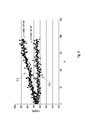
- Figure 5
- shows measurement curves of an analyte detection using the present invention, as compared to a conventional method.
Exemplary embodiments
-
In Figure 1, a cross-sectional view of a reagent container 110 according to the present invention is depicted. In this view, a casing 112 of the reagent container is depicted. Caps according to the present invention, which may be applied to the reagent container 110, are not depicted in this figure. Reference may be made to the caps as depicted in Figures 2A, 2B and 3. However, other caps according to the present invention may be used.
-
The casing encloses an interior 114 of the reagent container. The interior 114, in this specific embodiment, may comprise two compartments 116, 118 for storing a liquid (not depicted). The compartments 116, 118 may have the same size or, as depicted in Figure 1, may have different sizes for storing different quantities of the liquid.
-
Inside each compartment, in this specific embodiment, two chimneys 120, 122 may be located, the interior of which communicates with the remaining compartments 116, 118 via a small gap 124, 126 at the bottom of the chimneys 120, 122. The chimneys 120, 122 are adapted to prevent major fluctuations of the liquid level inside the chimneys 120, 122.
-
On the upper side of each compartment 116, the chimneys 120, 122 protrude from the casing 112 as lugs 128, 130. As indicated in Figure 1, each lug 128, 130 may comprise one or more locking elements 132, such as one or more threads. Further, as indicated in Figure 1, each lug 128, 130 may comprise one or more venting channels 134 for venting the interior 114.
-
In Figures 2A, 2B and 3, two different embodiments of a cap 136 according to the present invention are shown. Therein, Figure 2A shows a cross-sectional view of a first embodiment of the cap 136, cut along virtual line IIA-IIA in Fig. 2B, and Figure 2B shows a top view of the cap 136 according to this first embodiment. Figure 3 shows a cross-sectional view of a second embodiment of the cap 136 located inside an opening 138 of a reagent container 130, such as an opening 138 of a lug 128, 130.
-
As shown in the embodiment depicted in Figures 2A and 2B, the cap 136 comprises a frame 140, such as a molded plastic frame. In this embodiment or other embodiments, the frame fully or partially might be made of one or more plastic materials, such as plastic materials selected from the group consisting of polyethylene and polypropylene. In this embodiment, the cap 136 is designed as a screw-on cap comprising a connecting element 142 at its lower end, which, in this embodiment, might comprise one or more threads 144. This connecting element might interact with the locking element 132 on the lug 128, 130 depicted in Figure 1.
-
The cap 136 further comprises a cover plate 146, which, as depicted in Figure 2A, partially closes the opening 138 of the reagent container 110. The cover plate 146 is located on an outer side 148 of the cap 136, facing away from the reagent container 110. The cover plate 146 comprises at least one opening 150, such as a circular opening 150.
-
Beneath the cover plate 146, a sponge element 152 is located. The sponge element 152 may be disk-shaped and may comprise one or more sponge materials 154.
-
The sponge element is sandwiched between the cover plate 146 and at least one locking element 156 adapted to secure the sponge element 152 inside the frame 140. In this specific case, the locking element 156 preferably may be designed as a locking ring 158 having an outer diameter corresponding approximately to the inner diameter of the frame 140, such that the locking ring 158 may forcefully be pushed into the frame 140, thereby securing the sponge element 152 by frictional force. However, other locking elements 156 and/or other locking mechanisms of the sponge element 152 are possible, such as locking elements 156 based on a screwing mechanism and/or a snap-in-mechanism. Alternatively or additionally, the sponge element 152 can also be glued or bonded to the frame 140.
-
The cap 136 may further comprise one or more transport seals 160, as depicted in Figure 2A. As an example, the transport seal 160 may comprise one or more films, foils or membranes, such as a silicone membrane and/or a latex membrane and/or an aluminum foil. Other embodiments are possible.
-
As depicted in the top view in Figure 2B, the sponge element 152 is accessible through the opening 150 in the cover plate 146. As depicted in Figure 2B, the opening 150 may be off-centered with regard to the center of the cover plate 146. This is due to the fact that a point of perforation, in Figures 2A and 2B symbolically denoted by reference number 162, shall be located away from the venting channel 134 in Figure 1, in order to avoid a collision between the pipette and the venting channel 134 due to potential misalignments of the pipette.
-
The transport seal 160 preferably is designed as a closed element, without any perforations and/or incisions. During transport of the reagent container 110, the transport seal 160 may be designed to prevent leakage of reagents from the reagent container 110 through the cap 136. Before use, i.e. before and/or during the first pipetting process, the transport seal 160 may be removed, such as by peeling off the transport seal 160 from the cap, and/or may be perforated, such as by using a separate perforating element and/or by using a pipette.
-
The sponge element 152 further comprises one or more perforations 164 extending from an outer side 166 of the sponge element facing away from the interior 114 of the reagent container 110 to an inner side 168 of the sponge element 152 facing towards the interior 114 of reagent container. As depicted in Figure 2B, the at least one perforation 164 may comprise one or more slits 170, which, in this specific embodiment, preferably may be arranged in a cross-shaped manner. The slits 170 may meet at the center of perforation 162. Each slit 170 may comprise a small gap or may be closed. The perforations 164 allow for an easy penetration of a pipette through the sponge element 152.
-
As an exemplary embodiment for the sponge material 154, cellulose materials of medical quality and/or polyurethane materials of medical quality may be named. Thus, in a specific embodiment, cellulose materials available from Kettenbach GmbH & Co. KG, Eschenburg, Germany were used, such as Sugi® cellulose absorbent material, having an area density of 200 g/m2 or having an area density of 600 g/m2. As an alternative, polyurethane materials of medical quality, available from Filtrona Fibertec GmbH, Reinbek, Germany were used, of the type Medisponge® 30W, 30PW or W/PU. Alternatively or additionally, other sponge materials and/or other fiber materials may be used, such as non-woven or woven microfiber materials.
-
In Figure 3, an alternative embodiment of a cap 136 is depicted in a cross-sectional view. As opposed to the embodiment in Figures 2A and 2B showing a screw-on cap 136, the cap 136 in Figure 3 is designed to be fully or partially inserted into the opening 138 of the reagent container 110, such as into the opening 138 of one of the lugs 128, 130 of the reagent container 110. Again, the cap 136 comprises a frame 140, such as a frame 140 made of a molded plastic material and/or made of a metal material and/or made of a ceramic material. On its outer side, the frame may comprise one or more connecting elements 142 adapted to connect the cap 136 to the reagent container 110. In this case, preferably, the connecting element 142 is adapted to provide a connection to the reagent container 110 by at least one of a force-fit and a form-fit connection. Thus, as depicted in Figure 3, the at least one connecting element 142 may comprise at least one spring element 172, such as one or more spring arms 174. The spring element 172 may be molded as one piece with the remaining frame 140. However, other embodiments of connecting elements 142 are possible.
-
As shown in Figure 3, in this embodiment or in other embodiments such as in the screw-on embodiments of Figures 2A and 2B, more than one sponge element 152 may be provided. Thus, the at least one sponge element 152 may comprise at least one first sponge element 176 facing towards the interior 114 of the reagent container 110, and at least one second sponge element 178 facing away from the interior 114 of the reagent container 110. The first and second sponge element 176, 178 may have identical or different chemical and/or physical properties. Thus, the first and second sponge elements 176, 178 may have the same or different degrees of hydrophilic and/or hydrophobic properties. Thus, the first sponge element 176 may have hydrophobic properties, and the second sponge element 178 may have hydrophilic properties. However, other embodiments are possible.
-
The plurality of sponge elements 152 may be in close contact or may be spaced apart, as depicted in Figure 3. Thus, as depicted in Figure 3, the first and second sponge elements 176, 178 may be spaced apart, by forming at least one intermediate space 180 in between the first and second sponge elements 176, 178. As an example, the first and second sponge elements 176, 178 in this embodiment or in other embodiments may be spaced apart by 0.5 to 20 mm, more preferably by 1.0 to 15 mm and more preferably by 5.0 to 10.0 mm. In order to maintain a constant distance and spacing in between the first and second sponge elements 176, 178 and in order to enhance the structural stability of the cap 136, one or more spacers 182 may be interposed in between the first and second sponge elements 176, 178. Thus, the at least one spacer 182 may comprise one or more rings, tubes or other types of spacers.
-
Further, similar to the embodiment shown in Figures 2A and 2B, each of the sponge elements 152 comprises one or more perforations 164, such as one or more slits 170, each of the perforations 164 extending all the way through the sponge elements 152. Again, as an example, the slits may in a star-shaped and/or cross-shaped arrangement Other embodiments are possible.
-
In Figure 4, a schematic and highly simplified setup of an analysis device 184 for automatically detecting at least one analyte in a sample is depicted. The analysis device comprises at least one sample vessel 186 for receiving the sample, such as a cuvette or any other type of sample vessel 186. In the sample vessel 186, a detection reaction might take place for detecting the at least one analyte, such as an optically detectable reaction detectable by an optical detector 190. The analysis device 184 may further comprise one or more sample storage vessels 188 for repeatedly providing defined quantities of the sample.
-
The analysis device 184 further comprises one or more reagent containers 110 with one or more caps 136, such as the caps 136 depicted in the embodiments of Figures 2A to 2B or Figure 3. The at least one reagent container 110 comprises one or more reagents adapted to provoke the detection reaction inside the sample vessel 186.
-
The analysis device 184 further comprises one or more pipetting devices 192. The pipetting device 192 may comprise one or more pipettes 194 and, preferably, one or more motion stages 196. The at least one motion stage 196 is adapted to induce a relative motion of the pipette 194 and one or more of the elements 110, 186, 188 and/or other elements of the analysis device 184. Thus, the motion stage 196 may be adapted to provide a lateral movement of the pipette 194 in an x-y-direction, which symbolically is denoted by reference number 198 in Figure 4. Alternatively or additionally, the motion stage 196 may be adapted to perform a lateral movement in the x-y-direction 198 of one or more of the elements 110, 186 and 188. Thereby, by performing this relative movement in the lateral direction 198, the pipette 194 selectively may be positioned above one or more of these elements. Additionally, the motion stage 196 may be adapted to perform an up- and downward movement of the pipette 194 with regard to one or more of the elements 110, 186, 188, i.e. a movement in a z-direction 200. Again, additionally or alternatively to the option of moving the pipette 194, an up- and downward movement of one or more of the elements 110, 186 and 188 may be provided.
-
The pipetting device 192 further may comprise one or more additional elements, such as a suction device 202 and/or a pressurizing device 204. The suction device 202 may be adapted to provide an underpressure to the pipette 194, and the pressurizing device 204 may be adapted to provide an overpressure to the pipette 194.
-
The analysis device 184 further may comprise at least one cleaning station 206 adapted to automatically flush the pipette 194 with at least one cleaning liquid, preferably water, before inserting the pipette through the cap 136 into the reagent container 110. Thus, in the cleaning station 206, the cleaning liquid may be provided by at least one feeding line to the pipette 194 from the inside, such as from a back end of the pipette 194, preferably by applying an overpressure to the cleaning liquid. Additionally or alternatively, the outer side of the pipette 194 may be flushed with the cleaning liquid, such as by rinsing the outer side of the pipette 194 and/or a tip 208 of the pipette 194 with the cleaning liquid and/or by spraying the cleaning liquid onto the outer side of the pipette 194 and/or a tip 208 of the pipette 194. Additionally or alternatively, the pipette 208 may be dipped into a cleaning bath.
-
Similar to the relative movement provided by the motion stage 196 of the pipetting device 192, the motion stage 196 may further be adapted to provide a relative movement of the pipette 194 with regard to the cleaning station 206.
-
The analysis device 184 may further comprise one or more control units 210, such as one or more computers and/or data processing devices, adapted to control one or more processes of the automatic analysis of the analysis device 184. Thus, the control unit 210 may be adapted to control a sample-uptake from the sample storage vessel 188 and a transfer of a defined quantity of the sample into the sample vessel 186. Further, the control unit 210 may be adapted to provide one or more chemicals to the sample inside the sample vessel 186, such as from the reagent containers 110. Thus, optionally, one or more buffer solutions may be provided to the sample. Additionally or alternatively, one or more reagents may be provided to the sample from the reagent container 110. The control unit 210 may further be adapted to control a timing of the analysis process, such as by providing an appropriate time for supplying the sample, the buffer and/or the reagent to the sample vessel 186 and/or by providing an appropriate timing for optically detecting the detection reaction by using the optical detector 190 and/or any other detector.
-
As outlined above, the pipette 194 is forced through the cap 136 of the reagent container 110 when pipetting a defined quantity of liquid from the reagent container 110. Thereby, the tip 208 of the pipette 194 perforates the at least one sponge element 152 of the cap 136, preferably at the center of perforation 162. Preferably, the cap 136 is designed such that the force required for this perforation sums up to no more than 1.5 N, preferably to no more than 1.0 N. Before inserting the pipette 194 into the reagent container 110, a cleaning process may be performed by using the cleaning station 206. Remaining cleaning fluid, such as water, adhering to the outer side of the pipette 194 or the tip 208 of the pipette 194 is wiped off by the at least one sponge element 152 and is absorbed by the sponge material 154, thereby preventing a dilution of the liquid contained in the reagent container 110 by the cleaning liquid.
-
When using a cap 136 having more than one sponge element 152, such as by using the cap 136 according to the embodiment of Figure 3, the cleaning liquid is absorbed by the second sponge element 178 when inserting the pipette 194 into the reagent container 110, in a downward movement of the pipette 194 in Figure 4. When inserted into the reagent container 110, a suction procedure may take place, wherein the pipette 194 takes up a defined quantity of the liquid contained in the reagent container 110. Thereafter, an upward movement of the pipette 194 may take place, thereby removing the pipette 194 from the reagent container 110 through the cap 136. In this upward movement, liquid from the sample container 110 adhering to the outer side of the pipette 194 may be absorbed by the first sponge element 176. Thereby, a falsification of the analysis result by reagent quantities adhering to the outer side of the pipette 194 may be prevented. Thus, as outlined above, the first and second sponge elements 176, 178 may have different functions with regard to absorbing different types of liquids. Thus, the first sponge element 176 may be adapted and/or optimized to absorb liquid from the reagent container 110, whereas the second sponge element 178 may be adapted and/or optimized to absorb cleaning liquid, such as water.
-
When providing the reagent containers 110 to the analysis device 184, one or more transport caps of the reagent containers 110 may be replaced by one or more caps 136 according to the present invention. Alternatively, as outlined above, the cap 136 according to the present invention also may function as a storage and/or transport cap. For this purpose, as discussed in detail above, the transport caps 136 each may comprise one or more transport seals 160, which may prevent leakage of the liquid from the reagent container 110 during transport and/or storage. Before use in the analysis device 184, the transport seal 160 may be removed and/or may forcefully be perforated, such as by using a separate perforation device.
-
In Figure 5, an exemplary embodiment of a chemical analysis performed by the analysis device 184 of Figure 4 is depicted. In this exemplary embodiment, a simple drug test was repeatedly performed, by using reagents from the same reagent container 110. A cleaning step, as outlined with regard to Figure 4, was performed before each insertion of a pipette 194 into the reagent container 110. On the horizontal axis in Figure 5 (denoted by #) the number of the tests is performed. On the vertical axis, a concentration of a test analyte, given in ng/ml, is depicted.
-
The measurements depicted in Figure 5 were performed under two different conditions. Thus, reference number 212 denotes measurement results using a reagent container 110 without any cap, i.e. by leaving open the opening 138 of the reagent container 110. Contrarily, reference number 214 denotes a group of measurement results using a cap 136 according to the present invention.
-
In each case, 200 tests were performed. As can be seen by simple comparison of the measurement results 212 and 214, the analysis results without using the cap 136 strongly depend on the "history" of the reagent container 110, i.e. on the number of pipetting processes performed before the respective test. This is clearly due to the fact that the reagent stored in the reagent container 110 is diluted by cleaning fluid adhering to the outer side of the pipette 194 each time the pipette 194 is inserted into the reagent container 110. Contrarily, when using the cap 136 according to the present invention, the cleaning liquid is removed from the outer side of the pipette 136 before insertion of the pipette 136 into the reagent container 110. Consequently, the dilution of the reagent in the reagent container 110 is significantly suppressed. On the right hand side of Figure 5, functions of fit curves fitted to the measurement results 212, 214 are denoted. As can be seen, measurement results 212 may be fitted to a linear line having a slope of 1.1254, whereas the measurement results 214 are fitted to a straight line having a slope of 0.1153, which is significantly less. Additionally or alternatively to the slope of the linear lines, the initial values and end values of the measurement results 212, 214 may be used for comparison. Thus, the initial value of measurement curve 212 is 658 ng/ml, and the end value of measurement curve 212 is 880 ng/ml. Contrarily, in the measurement curve 214, using the cap 136 and the reagent container 110 according to the present invention, the initial value is 662 ng/ml, and the end value is 650 ng/ml. Thus, even though the initial values of both curves 212, 214 are approximately identical within the measurement accuracy, the end value of curve 214 is significantly reduced in comparison to the end value of curve 212. These measurement results impressively demonstrate the effect of the cap 136 according to the present invention.
-
List of reference numbers
- 110
- reagent container
- 112
- casing
- 114
- interior
- 116
- compartment
- 118
- compartment
- 120
- chimney
- 122
- chimney
- 124
- gap
- 126
- gap
- 128
- lug
- 130
- lug
- 132
- locking element
- 134
- venting channel
- 136
- cap
- 138
- opening
- 140
- frame
- 142
- connecting element
- 144
- thread
- 146
- cover plate
- 148
- outer side
- 150
- opening
- 152
- sponge element
- 154
- sponge material
- 156
- locking element
- 158
- locking ring
- 160
- transport seal
- 162
- point of perforation
- 164
- perforation
- 166
- outer side
- 168
- inner side
- 170
- slit
- 172
- spring element
- 174
- spring arm
- 176
- 1st sponge element
- 178
- 2nd sponge element
- 180
- intermediate space
- 182
- spacer
- 184
- analysis device
- 186
- sample vessel
- 188
- sample storage vessel
- 190
- optical detector
- 192
- pipetting device
- 194
- pipette
- 196
- motion stage
- 198
- x-y-direction
- 200
- z-direction
- 202
- suction device
- 204
- pressurizing device
- 206
- cleaning station
- 208
- tip
- 210
- control unit
- 212
- measurements without cap
- 214
- measurements with cap