EP2617347B1 - Endoscope - Google Patents
Endoscope Download PDFInfo
- Publication number
- EP2617347B1 EP2617347B1 EP12817267.3A EP12817267A EP2617347B1 EP 2617347 B1 EP2617347 B1 EP 2617347B1 EP 12817267 A EP12817267 A EP 12817267A EP 2617347 B1 EP2617347 B1 EP 2617347B1
- Authority
- EP
- European Patent Office
- Prior art keywords
- perpendicular directions
- directions
- bending
- bending operation
- touched region
- Prior art date
- Legal status (The legal status is an assumption and is not a legal conclusion. Google has not performed a legal analysis and makes no representation as to the accuracy of the status listed.)
- Not-in-force
Links
Images


Classifications
-
- A—HUMAN NECESSITIES
- A61—MEDICAL OR VETERINARY SCIENCE; HYGIENE
- A61B—DIAGNOSIS; SURGERY; IDENTIFICATION
- A61B1/00—Instruments for performing medical examinations of the interior of cavities or tubes of the body by visual or photographical inspection, e.g. endoscopes; Illuminating arrangements therefor
- A61B1/00002—Operational features of endoscopes
- A61B1/00039—Operational features of endoscopes provided with input arrangements for the user
- A61B1/00042—Operational features of endoscopes provided with input arrangements for the user for mechanical operation
-
- A—HUMAN NECESSITIES
- A61—MEDICAL OR VETERINARY SCIENCE; HYGIENE
- A61B—DIAGNOSIS; SURGERY; IDENTIFICATION
- A61B1/00—Instruments for performing medical examinations of the interior of cavities or tubes of the body by visual or photographical inspection, e.g. endoscopes; Illuminating arrangements therefor
- A61B1/00147—Holding or positioning arrangements
- A61B1/0016—Holding or positioning arrangements using motor drive units
-
- A—HUMAN NECESSITIES
- A61—MEDICAL OR VETERINARY SCIENCE; HYGIENE
- A61B—DIAGNOSIS; SURGERY; IDENTIFICATION
- A61B1/00—Instruments for performing medical examinations of the interior of cavities or tubes of the body by visual or photographical inspection, e.g. endoscopes; Illuminating arrangements therefor
- A61B1/005—Flexible endoscopes
- A61B1/0051—Flexible endoscopes with controlled bending of insertion part
- A61B1/0052—Constructional details of control elements, e.g. handles
-
- A—HUMAN NECESSITIES
- A61—MEDICAL OR VETERINARY SCIENCE; HYGIENE
- A61B—DIAGNOSIS; SURGERY; IDENTIFICATION
- A61B1/00—Instruments for performing medical examinations of the interior of cavities or tubes of the body by visual or photographical inspection, e.g. endoscopes; Illuminating arrangements therefor
- A61B1/04—Instruments for performing medical examinations of the interior of cavities or tubes of the body by visual or photographical inspection, e.g. endoscopes; Illuminating arrangements therefor combined with photographic or television appliances
- A61B1/05—Instruments for performing medical examinations of the interior of cavities or tubes of the body by visual or photographical inspection, e.g. endoscopes; Illuminating arrangements therefor combined with photographic or television appliances characterised by the image sensor, e.g. camera, being in the distal end portion
-
- G—PHYSICS
- G02—OPTICS
- G02B—OPTICAL ELEMENTS, SYSTEMS OR APPARATUS
- G02B23/00—Telescopes, e.g. binoculars; Periscopes; Instruments for viewing the inside of hollow bodies; Viewfinders; Optical aiming or sighting devices
- G02B23/24—Instruments or systems for viewing the inside of hollow bodies, e.g. fibrescopes
- G02B23/2476—Non-optical details, e.g. housings, mountings, supports
Definitions
- the present invention relates to an endoscope including an insertion section provided with a bending section which is configured to bend in first perpendicular directions perpendicular to longitudinal directions and in second perpendicular directions perpendicular to the longitudinal directions and perpendicular to the first perpendicular directions.
- Patent Literature 1 has disclosed an endoscope including an insertion section provided with a bending section which configured to bend in first perpendicular directions perpendicular to longitudinal directions and in second perpendicular directions perpendicular to the longitudinal directions and perpendicular to the first perpendicular directions.
- the first perpendicular directions are up-and-down directions (UD directions) of a subject image obtained by an imaging element
- the second perpendicular directions are left-and-right directions (LR directions) of the subject image.
- a first bending operation knob configured to perform a bending operation in the first perpendicular directions and a second bending operation knob configured to perform a bending operation in the second perpendicular directions are provided on an outer surface of a grip casing of a grip section.
- the second bending operation knob is located to an outside of the first bending operation knob, and provided coaxially with the first bending operation knob.
- Patent Literature 1 Jpn. UM Appln. KOKAI Publication No. 6-68711
- the second bending operation knob is located to the outside of the first bending operation knob, and provided coaxially with the first bending operation knob. Therefore, when a surgeon performs the bending operation in the first perpendicular directions and the bending operation in the second perpendicular directions by one of two hands, a finger of the surgeon does not easily reach the second bending operation knob.
- the second bending operation knob at a position different from that of the first bending operation knob on the outer surface of the grip casing in a state that the second bending operation knob is not coaxial with the first bending operation knob.
- the two bending operation knobs are un-coaxially provided at the different positions with respect to each other, the two bending operation knobs and members configured to transmit the bending operation take up more space in the grip section. Thus, sufficient space is not secured inside the grip casing.
- the present invention has been made in view of the aforementioned problems, and it is an object of the present invention to provide an endoscope in which an inflow of a liquid into an inside of a grip section is effectively prevented, sufficient space is secured inside the grip section, and a bending operation is easily performed.
- an endoscope includes that an insertion section including a bending section which is configured to bend in first perpendicular directions perpendicular to longitudinal directions and in second perpendicular directions perpendicular to the longitudinal directions and perpendicular to the first perpendicular directions; a grip section which includes a grip casing, and which is provided to a proximal direction side of the insertion section; a bending operation knob which is attached to the grip casing, and which is configured to input a bending operation of the bending section in the first perpendicular directions; a touched region detector which includes a touch surface provided in an outer surface of the grip casing and which is configured to detect, over time, a region of the touch surface that has been touched as a touched region when a bending operation of the bending section in the second perpendicular directions is input; a positional information calculator which is configure to calculate a positional information of the detected touched region over time; a positional
- an endoscope in which an inflow of a liquid into an inside of a grip section is effectively prevented, sufficient space is secured inside the grip section, and a bending operation is easily performed, ca be provided.
- a first embodiment of the present invention is described with reference to FIG. 1 to FIG. 11 .
- FIG. 1 and FIG. 2 are views showing an endoscope 1 according to the present embodiment.
- the endoscope 1 includes an insertion section 2 which is configured to be inserted into a body cavity and which extends in longitudinal directions, and a grip section 3 provided to a proximal direction side of the insertion section 2.
- One end of a universal cord 4 is connected to the grip section 3.
- a scope connector (not shown) is provided at the other end of the universal cord 4.
- the insertion portion 2 includes a distal rigid section 6, a bending section 7 provided to the proximal direction side of the distal rigid section 6, and a flexible tube section 8 provided to the proximal direction side of the bending section 7.
- the bending section 7 is configured to bend in first perpendicular directions (a direction of arrow U and a direction of arrow D in FIG. 1 ) perpendicular to the longitudinal directions, and in second perpendicular directions (a direction of arrow L and a direction of arrow R in FIG. 1 ) perpendicular to the longitudinal directions and perpendicular to the first perpendicular directions.
- An imaging element 11 such as a CCD is provided in a distal end portion of the insertion section 2.
- a distal end of an electrical signal line 13 is connected to the imaging element 11.
- a proximal end of the electrical signal line 13 is connected to an image processing unit 15 such as an image processor via the scope connector through an inside of the insertion section 2, an inside of the grip section 3, and an inside of the universal cord 4.
- a light guide (not shown) configured to guide light to illuminate a subject extends from the distal end portion of the insertion section 2 through the inside of the insertion section 2 along the longitudinal directions.
- a proximal end of the light guide is connected to a light source unit (not shown) via the scope connector through the inside of the grip section 3 and the inside of the universal cord 4.
- the first perpendicular directions correspond to up-and-down directions (UD directions) of a subject image obtained (pictured) by the imaging element 11.
- the second perpendicular directions correspond to left-and-right directions (LR directions) of the subject image.
- the grip section 3 includes a grip casing 17 which is an exterior.
- a bending operation knob 19 is attached to the grip casing 17.
- a bending operation of the bending section 7 in the first perpendicular directions is performed (input) by a rotation of the bending operation knob 19.
- the space between the bending operation knob 19 and the grip casing 17 is kept watertight.
- FIG. 3 is a view showing the configuration of the grip section 3.
- the grip casing 17 includes a first outer surface portion 21 in which an outer surface faces toward one of the second perpendicular directions (the direction of arrow L and the direction of arrow R in FIG. 1 and FIG. 3 ), and a second outer surface portion 22 in which an outer surface faces toward one of the first perpendicular directions (the direction of arrow U and the direction of arrow D in FIG. 1 and FIG. 3 ).
- the bending operation knob 19 is provided on the first outer surface portion 21.
- the bending operation knob 19 is attached to the first outer surface portion 21 so that its rotation axis S is parallel to the second perpendicular directions.
- the bending operation knob 19 is rotated substantially parallel to the first perpendicular directions by the bending operation.
- a first pulley 25 is provided inside the grip casing 17.
- the first pulley 25 is rotated by the bending operation of the bending operation knob 19 in the first perpendicular directions.
- Proximal ends of two first bending wires 27A and 27B are connected to the first pulley 25.
- Distal ends of the first bending wires 27A and 27B are connected to a distal end portion of the bending section 7 through an inside of the flexible tube section 8.
- One of the first bending wires 27A and 27B is pulled by the rotation of the first pulley 25.
- the first bending wire 27A is pulled, the bending section 7 bends toward the direction of arrow U in FIG. 1 .
- the first bending wire 27B is pulled, the bending section 7 bends toward the direction of arrow D in FIG. 1 . In this way, the bending section 7 bends in the first perpendicular directions.
- a slide pad 31 which is a touched region detector is provided to the grip casing 17.
- the bending operation of the bending section 7 in the second perpendicular directions is performed (input) by the slide pad 31.
- the slide pad 31 includes a touch surface 32 located on the second outer surface portion 22 of the outer surface of the grip casing 17.
- the slide pad 31 detects, with time, a region of the touch surface 32 that has been touched as a touched region.
- the slide pad 31 detects, as a touched region, a region that has been touched by a surgeon.
- the control unit 35 includes a positional information calculator 37 configured to calculate a positional information of the detected touched region with time.
- the positional information calculator 37 is configured to calculate a position of a center of gravity of the touched region as the positional information of the touched region.
- the control unit 35 includes a positional change detector 39.
- the positional change detector 39 is configured to detect a positional change of the touched region when the bending operation of the bending section 7 in the second perpendicular directions is performed (input).
- the positional change detector 39 includes a displacement amount calculator 41. The displacement amount calculator 41 will be described in detail later.
- a motor 43 which is a drive member is provided inside the grip casing 17.
- the motor 43 is electrically connected to the control unit 35 via an electrical signal line 45.
- the control unit 35 includes a drive controller 47 configured to control a drive state of the motor 43.
- the drive controller 47 is configured to control the drive state of the motor 43 in accordance with the positional change of the touched region detected by the positional change detector 39.
- An angle sensor 48 is provided inside the grip casing 17.
- the angle sensor 48 is electrically connected to the control unit 35 via an electrical signal line 49.
- the angle sensor 48 is configured to detect a rotation angle of the motor 43.
- the drive controller 47 is configured to control the drive state of the motor 43 in accordance with the detected rotation angle of the motor 43.
- a second pulley 51 is provided inside the grip casing 17.
- the second pulley 51 is rotated when the motor 43 is driven by the bending operation in the second perpendicular directions in the slide pad 31.
- Proximal ends of two second bending wires 53A and 53B are connected to the second pulley 51.
- Distal ends of the second bending wires 53A and 53B are connected to the distal end portion of the bending section 7 through the inside of the flexible tube section 8.
- One of the second bending wires 53A and 53B is pulled by the rotation of the second pulley 51.
- the second bending wire 53A is pulled, the bending section 7 bends toward the direction of arrow L in FIG. 1 .
- the second bending wire 53B is pulled, the bending section 7 bends toward the direction of arrow R in FIG. 1 . In this way, the bending section 7 bends in the second perpendicular directions when the motor 43 is driven.
- FIG. 4 is a diagram illustrating processing in the displacement amount calculator 41.
- a touched region Ai is detected by the slide pad 31 at a time ti.
- the center of gravity Gi of the touched region Ai is calculated by the positional information calculator 37 as positional information of the touched region Ai.
- the position of the touched region is changed by the bending operation of the bending section 7 in the second perpendicular directions.
- a touched region Ai+1 is detected by the slide pad 31 at a time ti+1.
- the center of gravity Gi+1 of the touched region Ai+1 is calculated by the positional information calculator 37 as positional information of the touched region Ai+1.
- the position of the touched region is changed from the center of gravity Gi to the center of gravity Gi+1 by the bending operation of the bending section 7 in the second perpendicular directions.
- the displacement amount calculator 41 calculates a displacement amount of the touched region in the second perpendicular directions (the direction of arrow L and the direction of arrow R in FIG. 4 ) which are reference directions in the positional change of the touched region.
- a displacement amount ⁇ in the second perpendicular directions between the center of gravity Gi and the center of gravity Gi+1 is calculated.
- the drive controller 47 controls the drive state of the motor 43 in accordance with the calculated displacement amount ⁇ of the touched region in the second perpendicular directions. Therefore, the bending portion 7 performs a bending motion in the second perpendicular directions in accordance with the calculated displacement amount ⁇ of the touched region in the second perpendicular directions.
- the present invention is not limited thereto.
- the displacement amount calculator 41 has only to calculate a displacement amount of the touched region in the reference directions parallel to the outer surface of the grip casing 17 during the positional change of the touched region.
- the drive controller 47 has only to control the drive state of the motor 43 in accordance with the displacement amount of the touched region in the reference directions.
- FIG. 5 is a view showing a state in which the surgeon grips the grip casing 17 with one of two hands.
- the bending operation knob 19 is rotated with a thumb F1 to perform (input) the bending operation of the bending section 7 in the first perpendicular directions.
- a forefinger F2 or a middle finger F3 is moved on the touch surface 32 of the slide pad 31 to perform (input) the bending operation of the bending section 7 in the second perpendicular directions.
- a bending operation of a bending section 7A in the first perpendicular directions (the direction of arrow U and the direction of arrow D in FIG. 6 ) is performed by a first bending operation knob 19A
- a bending operation of the bending section 7A in the second perpendicular directions (the direction of arrow L and the direction of arrow R in FIG. 6 ) is performed by a second bending operation knob 31A.
- the second bending operation knob 31A is located to an outside of the first bending operation knob 19A, and provided coaxially with the first bending operation knob 19A.
- the bending operation knob 19 is attached to the first outer surface portion 21 in which the outer surface of the grip casing 17 faces toward one of the second perpendicular directions, and the touch surface 32 of the slide pad 31, which is the touched region detector, is located to the second outer surface portion 22 in which the outer surface of the grip casing 17 faces toward one of the first perpendicular directions. Therefore, when the surgeon grips the grip casing 17 with one hand, the bending operation knob 19 is easily rotated with the thumb F1, and the bending operation of the bending section 7 in the first perpendicular directions is easily performed (input). Moreover, the forefinger F2 or the middle finger F3 is easily moved on the touch surface 32 of the slide pad 31, and the bending operation of the bending section 7 in the second perpendicular directions is easily performed (input).
- the bending operation knob 19 is attached to the first outer surface portion 21 so that its rotation axis S is parallel to the second perpendicular directions.
- the bending operation knob 19 is rotated substantially parallel to the first perpendicular directions by the bending operation.
- the rotation directions of the bending operation knob 19 are substantially parallel to the first perpendicular directions in which the bending portion 7 is bent by the bending operation, the surgeon more easily perform (input) the bending operation of the bending section 7 in the first perpendicular directions.
- the displacement amount calculator 41 calculates the displacement amount ⁇ of the touched region in the second perpendicular directions which are the reference directions in the positional change of the touched region on the touch surface 32.
- the drive state of the motor 43 is controlled in accordance with the displacement amount ⁇ of the touched region in the second perpendicular directions. That is, the bending portion 7 bends in the second perpendicular directions in accordance with the displacement amount ⁇ of the touched region in the second perpendicular directions in the bending operation.
- the bending operation of the bending section 7 in the second perpendicular directions is more easily performed (input).
- the second perpendicular directions in which the bending portion 7 is bent by the bending operation are the reference directions of the displacement amount ⁇ , so that the surgeon more easily perform the bending operation of the bending section 7 in the second perpendicular directions.
- FIG. 7 and FIG. 8 are diagrams illustrating the bending operation of the bending section 7 in the second perpendicular directions.
- the forefinger F2 or the middle finger F3 is moved (arrow B1 in FIG. 7 ) on the touch surface 32 to increase the displacement amount in the second perpendicular directions (the direction of arrow L and the direction of arrow R in FIG. 7 and FIG. 8 ). That is, the forefinger F2 or the middle finger F3 is moved on the touch surface 32 substantially parallel to the second perpendicular directions which are the reference directions.
- FIG. 7 in order to increase the amount (degree) of bending of the bending section 7 in the second perpendicular directions, the forefinger F2 or the middle finger F3 is moved (arrow B1 in FIG. 7 ) on the touch surface 32 to increase the displacement amount in the second perpendicular directions (the direction of arrow L and the direction of arrow R in FIG. 7 and FIG. 8 ). That is, the forefinger F2 or the middle finger F3
- the forefinger F2 or the middle finger F3 is moved (arrow B2 in FIG. 8 ) on the touch surface 32 to decrease the displacement amount in the second perpendicular directions. That is, the forefinger F2 or the middle finger F3 is moved on the touch surface 32 to deviate from the second perpendicular directions which are the reference directions.
- the drive state of a motor 43B is controlled in accordance with an amount (degree) of movement during the positional change of the touched region. That is, when the position is changed from a touched region A'i to a touched region A'i+1 by the bending operation in the second perpendicular directions, an amount of movement ⁇ from the center of gravity G'i to the center of gravity G'i+1 is calculated.
- the drive state of the motor 43B is controlled in accordance with the amount of movement ⁇ , and a bending section 7B performs bending motion in the second perpendicular directions.
- the forefinger F2 or the middle finger F3 is moved (arrow B2 in FIG. 8 ) on the touch surface 32 to decrease the displacement amount in the second perpendicular directions. That is, the forefinger F2 or the middle finger F3 is moved on the touch surface 32 to deviate from the second perpendicular directions which are the reference directions.
- the amount of movement of the forefinger F2 or the middle finger F3 does not need to be decreased as long as the displacement amount of the touched region in the second perpendicular directions is small. Therefore, even when the amount (degree) of bending of the bending section 7 in the second perpendicular directions is small, the surgeon easily performs (inputs) the bending operation of the bending section 7 in the second perpendicular directions.
- an endoscope 1C shown in FIG. 11 as a second comparative example.
- a bending operation of a bending section 7C in the first perpendicular directions (the direction of arrow U and the direction of arrow D in FIG. 11 ) is performed (input) by a first bending operation knob 19C
- a bending operation of the bending section 7C in the second perpendicular directions (the direction of arrow L and the direction of arrow R in FIG. 11 ) is performed (input) by a second bending operation knob 31C.
- the second bending operation knob 31C is provided at a position different from that of the first bending operation knob 19C in a state that the second bending operation knob 31C is not coaxial with the first bending operation knob 19C.
- the bending operation knobs 19C and 31C and members configured to transmit the bending operation take up more space in a grip section 3C. Thus, sufficient space is not secured inside a grip casing 17C.
- the two bending operation knobs 19C and 31C that is rotatable relative to the grip casing 17C are attached to the grip casing 17C at different positions with respect to each other, so that it is difficult to keep the space between each of the bending operation knobs 19C and 31C and the grip casing 17C watertight. This facilitates the inflow of a liquid from the outside of the grip casing 17C into the inside of the grip casing 17C. Therefore, the washing of the grip section 3C after use is difficult.
- the bending operation of the bending section 7 in the second perpendicular directions is performed (input) by the slide pad 31 which is the touched region detector.
- the slide pad 31 is shaped like a flat plate, and therefore takes up less space than the second bending operation knob 31C in the second comparative example.
- Members such as the electrical signal line 33, the motor 43, and the electrical signal line 45, which are configured to allow the second pulley 51 to be rotated by the bending operation in the slide pad 31, also take up little space. Accordingly, sufficient space is secured inside the grip casing 17.
- the slide pad 31 is fixed to the grip casing 17. It is thus easy to keep the space between the slide pad 31 and the grip casing 17 watertight. This efficiently prevents the inflow of a liquid from the outside of the grip casing 17 into the inside of the grip casing 17. Therefore, the grip section 3 is easily washed after use.
- the first perpendicular directions correspond to the up-and-down directions (UD directions) of the subject image obtained (captured) by the imaging element 11, and the second perpendicular directions correspond to the left-and-right directions (LR directions) of the subject image. Therefore, when the bending section 7 is bent in the up-and-down directions, force applied to the bending operation knob 19 by the surgeon is dynamically (mechanically) transmitted to the bending section 7. On the other hand, when the bending section 7 is bent in the left-and-right directions, the motor 42 is driven by an electrical signal generated by the bending operation in the slide pad 31, so that force applied to the slide pad 31 by the surgeon is not dynamically transmitted to the bending section 7.
- the bending section 7 when the bending section 7 is bent, the bending section 7 is bent mainly in the up-and-down directions, and is hardly bent in the left-and-right directions. That is, in the bending operation in the up-and-down directions which is frequently performed, the force applied by the surgeon is dynamically transmitted to the bending section 7. Therefore, the surgeon can feel a proper sense of operation in the bending operation in the up-and-down directions. Consequently, the surgeon more easily performs (inputs) the bending operation of the bending section 7.
- the force applied to the slide pad 31 by the surgeon does not need to be configured to be dynamically transmitted to the bending section 7. That is, even when the surgeon cannot feel a proper sense of operation in the bending operation in the left-and-right directions, there is no great effect on the bending operation of the bending section 7.
- the endoscope 1 having the configuration described above has the following advantageous effects. That is, in the endoscope 1, the bending operation knob 19 is attached to the first outer surface portion 21 in which the outer surface of the grip casing 17 faces toward one of the second perpendicular directions, and the touch surface 32 of the slide pad 31, which is the touched region detector, is located in the second outer surface portion 22 in which the outer surface of the grip casing 17 faces toward one of the first perpendicular directions. Therefore, when the surgeon grips the grip casing 17 with one of two hands, the bending operation knob 19 is easily rotated with the thumb F1, and the bending operation of the bending section 7 in the first perpendicular directions is easily performed (input).
- the forefinger F2 or the middle finger F3 is easily moved on the touch surface 32 of the slide pad 31, and the bending operation of the bending section 7 in the second perpendicular directions is easily performed (input). Consequently, operability in the bending operation of the bending section 7 can be improved.
- the bending operation of the bending section 7 in the second perpendicular directions is performed by the slide pad 31 which is the touched region detector.
- the slide pad 31 is shaped like a flat plate, and therefore takes up little space.
- Members such as the electrical signal line 33, the motor 43, and the electrical signal line 45, which is configured to allow the second pulley 51 to be rotated by the bending operation in the slide pad 31, also take up little space. Accordingly, sufficient space can be secured inside the grip casing 17.
- the slide pad 31 is fixed to the grip casing 17. It is thus possible to easily keep the space between the slide pad 31 and the grip casing 17 watertight. This efficiently prevents the inflow of a liquid from the outside of the grip casing 17 into the inside of the grip casing 17. Therefore, the grip section 3 can be easily washed after use.
Description
- The present invention relates to an endoscope including an insertion section provided with a bending section which is configured to bend in first perpendicular directions perpendicular to longitudinal directions and in second perpendicular directions perpendicular to the longitudinal directions and perpendicular to the first perpendicular directions.
-
Patent Literature 1 has disclosed an endoscope including an insertion section provided with a bending section which configured to bend in first perpendicular directions perpendicular to longitudinal directions and in second perpendicular directions perpendicular to the longitudinal directions and perpendicular to the first perpendicular directions. Here, the first perpendicular directions are up-and-down directions (UD directions) of a subject image obtained by an imaging element, and the second perpendicular directions are left-and-right directions (LR directions) of the subject image. In this endoscope, a first bending operation knob configured to perform a bending operation in the first perpendicular directions and a second bending operation knob configured to perform a bending operation in the second perpendicular directions are provided on an outer surface of a grip casing of a grip section. The second bending operation knob is located to an outside of the first bending operation knob, and provided coaxially with the first bending operation knob. - Patent Literature 1: Jpn. UM Appln. KOKAI Publication No.
6-68711 - In general, during the use of the endoscope, it may be necessary to perform both the bending operation in the first perpendicular directions and the bending operation in the second perpendicular directions by one of two hands. In the endoscope according to
Patent Literature 1, the second bending operation knob is located to the outside of the first bending operation knob, and provided coaxially with the first bending operation knob. Therefore, when a surgeon performs the bending operation in the first perpendicular directions and the bending operation in the second perpendicular directions by one of two hands, a finger of the surgeon does not easily reach the second bending operation knob. As the first bending operation knob and the second bending operation knob are coaxial, directions in which the first bending operation knob is rotated by the bending operation are the same as directions in which the second bending operation knob is rotated by the bending operation. As the directions in which the first bending operation knob is rotated during the bending operation in the first perpendicular directions is the same as the directions in which the second bending operation knob is rotated during the bending operation in the second perpendicular directions perpendicular to the first perpendicular directions, the surgeon cannot easily perform the bending operation of the bending section in the second perpendicular directions. As a result, in the endoscope according toPatent Literature 1, operability in the bending operation of the bending section deteriorates. - Here, it is possible to provide the second bending operation knob at a position different from that of the first bending operation knob on the outer surface of the grip casing in a state that the second bending operation knob is not coaxial with the first bending operation knob. However, when the two bending operation knobs are un-coaxially provided at the different positions with respect to each other, the two bending operation knobs and members configured to transmit the bending operation take up more space in the grip section. Thus, sufficient space is not secured inside the grip casing. Moreover, as the two bending operation knobs that can rotate relative to the grip casing are attached to the grip casing at different positions with respect to each other, it is difficult to keep a space located between each bending operation knob and the grip casing watertight as compared with the two bending operation knobs that are coaxially provided. This facilitates an inflow of a liquid from an outside of the grip casing into the inside of the grip casing. Therefore, the washing of the grip section after use is difficult.
- The present invention has been made in view of the aforementioned problems, and it is an object of the present invention to provide an endoscope in which an inflow of a liquid into an inside of a grip section is effectively prevented, sufficient space is secured inside the grip section, and a bending operation is easily performed.
- To solve above mentioned problems, according to one aspect of the invention, an endoscope according to
claim 1 is provided. It includes that an insertion section including a bending section which is configured to bend in first perpendicular directions perpendicular to longitudinal directions and in second perpendicular directions perpendicular to the longitudinal directions and perpendicular to the first perpendicular directions; a grip section which includes a grip casing, and which is provided to a proximal direction side of the insertion section; a bending operation knob which is attached to the grip casing, and which is configured to input a bending operation of the bending section in the first perpendicular directions; a touched region detector which includes a touch surface provided in an outer surface of the grip casing and which is configured to detect, over time, a region of the touch surface that has been touched as a touched region when a bending operation of the bending section in the second perpendicular directions is input; a positional information calculator which is configure to calculate a positional information of the detected touched region over time; a positional change detector which is configured to detect, in accordance with the positional information of the touched region over time, a positional change of the touched region when the bending operation of the bending section in the second perpendicular directions is input; a drive member which is configured to be driven to bend the bending section in the second perpendicular directions; and a drive controller which is configured to control a drive state of the drive member in accordance with the positional change of the touched region. - According to the present invention, an endoscope, in which an inflow of a liquid into an inside of a grip section is effectively prevented, sufficient space is secured inside the grip section, and a bending operation is easily performed, ca be provided.
-
-
FIG. 1 is a schematic perspective view showing an endoscope according to a first embodiment of the present invention; -
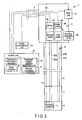
FIG. 2 is a block diagram showing the endoscope according to the first embodiment; -
FIG. 3 is a schematic perspective view showing the configuration of a grip section of the endoscope according to the first embodiment; -
FIG. 4 is a schematic diagram illustrating processing in a displacement amount calculator in the endoscope according to the first embodiment; -
FIG. 5 is a schematic perspective view showing a state in which a surgeon grips a grip casing of the endoscope according to the first embodiment with one hand; -
FIG. 6 is a schematic perspective view showing an endoscope according a first comparative example; -
FIG. 7 is a schematic diagram showing the bending operation of a bending section in second perpendicular directions when an amount (degree) of bending of the bending section of the endoscope according to the first embodiment in the second perpendicular directions is increased; -
FIG. 8 is a schematic diagram showing the bending operation of the bending section in the second perpendicular directions when the amount (degree) of bending of the bending section of the endoscope according to the first embodiment in the second perpendicular directions is decreased; -
FIG. 9 is a schematic diagram showing a state in which a position of a touched region on a touch surface is changed by the bending operation in the second perpendicular directions in a slide pad according to a referential example; -
FIG. 10 is a schematic diagram showing the bending operation of the bending section in the second perpendicular directions when the amount of bending of the bending section according to the referential example in the second perpendicular directions decreased; and -
FIG. 11 is a schematic perspective view showing an endoscope according a second comparative example. - A first embodiment of the present invention is described with reference to
FIG. 1 to FIG. 11 . -
FIG. 1 andFIG. 2 are views showing anendoscope 1 according to the present embodiment. As shown inFIG. 1 andFIG. 2 , theendoscope 1 includes aninsertion section 2 which is configured to be inserted into a body cavity and which extends in longitudinal directions, and agrip section 3 provided to a proximal direction side of theinsertion section 2. One end of auniversal cord 4 is connected to thegrip section 3. A scope connector (not shown) is provided at the other end of theuniversal cord 4. - The
insertion portion 2 includes a distalrigid section 6, abending section 7 provided to the proximal direction side of the distalrigid section 6, and aflexible tube section 8 provided to the proximal direction side of thebending section 7. Thebending section 7 is configured to bend in first perpendicular directions (a direction of arrow U and a direction of arrow D inFIG. 1 ) perpendicular to the longitudinal directions, and in second perpendicular directions (a direction of arrow L and a direction of arrow R inFIG. 1 ) perpendicular to the longitudinal directions and perpendicular to the first perpendicular directions. - An
imaging element 11 such as a CCD is provided in a distal end portion of theinsertion section 2. A distal end of anelectrical signal line 13 is connected to theimaging element 11. A proximal end of theelectrical signal line 13 is connected to animage processing unit 15 such as an image processor via the scope connector through an inside of theinsertion section 2, an inside of thegrip section 3, and an inside of theuniversal cord 4. A light guide (not shown) configured to guide light to illuminate a subject extends from the distal end portion of theinsertion section 2 through the inside of theinsertion section 2 along the longitudinal directions. A proximal end of the light guide is connected to a light source unit (not shown) via the scope connector through the inside of thegrip section 3 and the inside of theuniversal cord 4. Here, the first perpendicular directions correspond to up-and-down directions (UD directions) of a subject image obtained (pictured) by theimaging element 11. The second perpendicular directions correspond to left-and-right directions (LR directions) of the subject image. - The
grip section 3 includes agrip casing 17 which is an exterior. Abending operation knob 19 is attached to thegrip casing 17. A bending operation of thebending section 7 in the first perpendicular directions is performed (input) by a rotation of thebending operation knob 19. The space between thebending operation knob 19 and thegrip casing 17 is kept watertight. -
FIG. 3 is a view showing the configuration of thegrip section 3. As shown inFIG. 1 andFIG. 3 , thegrip casing 17 includes a firstouter surface portion 21 in which an outer surface faces toward one of the second perpendicular directions (the direction of arrow L and the direction of arrow R inFIG. 1 andFIG. 3 ), and a secondouter surface portion 22 in which an outer surface faces toward one of the first perpendicular directions (the direction of arrow U and the direction of arrow D inFIG. 1 andFIG. 3 ). Thebending operation knob 19 is provided on the firstouter surface portion 21. Thebending operation knob 19 is attached to the firstouter surface portion 21 so that its rotation axis S is parallel to the second perpendicular directions. Thus, the bendingoperation knob 19 is rotated substantially parallel to the first perpendicular directions by the bending operation. - As shown in
FIG. 2 , afirst pulley 25 is provided inside thegrip casing 17. Thefirst pulley 25 is rotated by the bending operation of the bendingoperation knob 19 in the first perpendicular directions. Proximal ends of twofirst bending wires first pulley 25. Distal ends of thefirst bending wires bending section 7 through an inside of theflexible tube section 8. One of thefirst bending wires first pulley 25. When thefirst bending wire 27A is pulled, thebending section 7 bends toward the direction of arrow U inFIG. 1 . On the other hand, when thefirst bending wire 27B is pulled, thebending section 7 bends toward the direction of arrow D inFIG. 1 . In this way, thebending section 7 bends in the first perpendicular directions. - As shown in
FIG. 1 to FIG. 3 , aslide pad 31 which is a touched region detector is provided to thegrip casing 17. The bending operation of thebending section 7 in the second perpendicular directions is performed (input) by theslide pad 31. Theslide pad 31 includes atouch surface 32 located on the secondouter surface portion 22 of the outer surface of thegrip casing 17. During the bending operation in the second perpendicular directions, theslide pad 31 detects, with time, a region of thetouch surface 32 that has been touched as a touched region. In accordance with pressure or static electricity, theslide pad 31 detects, as a touched region, a region that has been touched by a surgeon. - As shown in
FIG. 2 , one end of anelectrical signal line 33 is connected to theslide pad 31. The other end of theelectrical signal line 33 is connected to acontrol unit 35 through the inside of theuniversal cord 4. Thecontrol unit 35 includes apositional information calculator 37 configured to calculate a positional information of the detected touched region with time. Thepositional information calculator 37 is configured to calculate a position of a center of gravity of the touched region as the positional information of the touched region. - The
control unit 35 includes apositional change detector 39. In accordance with the positional information of the touched region with time, thepositional change detector 39 is configured to detect a positional change of the touched region when the bending operation of thebending section 7 in the second perpendicular directions is performed (input). Thepositional change detector 39 includes adisplacement amount calculator 41. Thedisplacement amount calculator 41 will be described in detail later. - A
motor 43 which is a drive member is provided inside thegrip casing 17. Themotor 43 is electrically connected to thecontrol unit 35 via anelectrical signal line 45. Thecontrol unit 35 includes adrive controller 47 configured to control a drive state of themotor 43. Thedrive controller 47 is configured to control the drive state of themotor 43 in accordance with the positional change of the touched region detected by thepositional change detector 39. - An
angle sensor 48 is provided inside thegrip casing 17. Theangle sensor 48 is electrically connected to thecontrol unit 35 via anelectrical signal line 49. Theangle sensor 48 is configured to detect a rotation angle of themotor 43. Thedrive controller 47 is configured to control the drive state of themotor 43 in accordance with the detected rotation angle of themotor 43. - As shown in
FIG. 2 , asecond pulley 51 is provided inside thegrip casing 17. Thesecond pulley 51 is rotated when themotor 43 is driven by the bending operation in the second perpendicular directions in theslide pad 31. Proximal ends of twosecond bending wires second pulley 51. Distal ends of thesecond bending wires bending section 7 through the inside of theflexible tube section 8. One of thesecond bending wires second pulley 51. When thesecond bending wire 53A is pulled, thebending section 7 bends toward the direction of arrow L inFIG. 1 . On the other hand, when thesecond bending wire 53B is pulled, thebending section 7 bends toward the direction of arrow R inFIG. 1 . In this way, thebending section 7 bends in the second perpendicular directions when themotor 43 is driven. -
FIG. 4 is a diagram illustrating processing in thedisplacement amount calculator 41. As shown inFIG. 4 , a touched region Ai is detected by theslide pad 31 at a time ti. At the same time, the center of gravity Gi of the touched region Ai is calculated by thepositional information calculator 37 as positional information of the touched region Ai. The position of the touched region is changed by the bending operation of thebending section 7 in the second perpendicular directions. A touched region Ai+1 is detected by theslide pad 31 at atime ti+ 1. At the same time, the center of gravity Gi+1 of the touched region Ai+1 is calculated by thepositional information calculator 37 as positional information of the touched region Ai+1. As described above, the position of the touched region is changed from the center of gravity Gi to the center of gravity Gi+1 by the bending operation of thebending section 7 in the second perpendicular directions. - The
displacement amount calculator 41 calculates a displacement amount of the touched region in the second perpendicular directions (the direction of arrow L and the direction of arrow R inFIG. 4 ) which are reference directions in the positional change of the touched region. A displacement amount δ in the second perpendicular directions between the center of gravity Gi and the center of gravity Gi+1 is calculated. Thedrive controller 47 controls the drive state of themotor 43 in accordance with the calculated displacement amount δ of the touched region in the second perpendicular directions. Therefore, the bendingportion 7 performs a bending motion in the second perpendicular directions in accordance with the calculated displacement amount δ of the touched region in the second perpendicular directions. - Although the drive state of the
motor 43 is controlled in accordance with the displacement amount δ of the touched region in the second perpendicular directions in the present embodiment, the present invention is not limited thereto. Thedisplacement amount calculator 41 has only to calculate a displacement amount of the touched region in the reference directions parallel to the outer surface of thegrip casing 17 during the positional change of the touched region. Further, thedrive controller 47 has only to control the drive state of themotor 43 in accordance with the displacement amount of the touched region in the reference directions. - Now, the functions of the
endoscope 1 are described.FIG. 5 is a view showing a state in which the surgeon grips thegrip casing 17 with one of two hands. As shown inFIG. 5 , when the surgeon grips thegrip casing 17 with one hand, the bendingoperation knob 19 is rotated with a thumb F1 to perform (input) the bending operation of thebending section 7 in the first perpendicular directions. A forefinger F2 or a middle finger F3 is moved on thetouch surface 32 of theslide pad 31 to perform (input) the bending operation of thebending section 7 in the second perpendicular directions. - Here, suppose an
endoscope 1A shown inFIG. 6 as a first comparative example. In theendoscope 1A, a bending operation of a bending section 7A in the first perpendicular directions (the direction of arrow U and the direction of arrow D inFIG. 6 ) is performed by a firstbending operation knob 19A, and a bending operation of the bending section 7A in the second perpendicular directions (the direction of arrow L and the direction of arrow R inFIG. 6 ) is performed by a secondbending operation knob 31A. In theendoscope 1A, the secondbending operation knob 31A is located to an outside of the firstbending operation knob 19A, and provided coaxially with the firstbending operation knob 19A. Therefore, when the surgeon perform both the bending operation in the first perpendicular direction and the bending operation in the second perpendicular direction with one of two hands, the finger of the surgeon does not easily reach the secondbending operation knob 31A. As the firstbending operation knob 19A and the secondbending operation knob 31A are coaxial, directions in which the firstbending operation knob 19A is rotated by the bending operation is the same as directions in which the secondbending operation knob 31A is rotated by the bending operation. As the directions in which the firstbending operation knob 19A is rotated by the bending operation in the first perpendicular directions is the same as the directions in which the secondbending operation knob 31A is rotated by the bending operation in the second perpendicular directions perpendicular to the first perpendicular directions, the surgeon cannot easily perform the bending operation of the bending section 7A in the second perpendicular directions. - In contrast, in the
endoscope 1 according to the present embodiment, the bendingoperation knob 19 is attached to the firstouter surface portion 21 in which the outer surface of thegrip casing 17 faces toward one of the second perpendicular directions, and thetouch surface 32 of theslide pad 31, which is the touched region detector, is located to the secondouter surface portion 22 in which the outer surface of thegrip casing 17 faces toward one of the first perpendicular directions. Therefore, when the surgeon grips thegrip casing 17 with one hand, the bendingoperation knob 19 is easily rotated with the thumb F1, and the bending operation of thebending section 7 in the first perpendicular directions is easily performed (input). Moreover, the forefinger F2 or the middle finger F3 is easily moved on thetouch surface 32 of theslide pad 31, and the bending operation of thebending section 7 in the second perpendicular directions is easily performed (input). - In the
endoscope 1, the bendingoperation knob 19 is attached to the firstouter surface portion 21 so that its rotation axis S is parallel to the second perpendicular directions. Thus, the bendingoperation knob 19 is rotated substantially parallel to the first perpendicular directions by the bending operation. As the rotation directions of the bendingoperation knob 19 are substantially parallel to the first perpendicular directions in which the bendingportion 7 is bent by the bending operation, the surgeon more easily perform (input) the bending operation of thebending section 7 in the first perpendicular directions. - In the
endoscope 1, thedisplacement amount calculator 41 calculates the displacement amount δ of the touched region in the second perpendicular directions which are the reference directions in the positional change of the touched region on thetouch surface 32. The drive state of themotor 43 is controlled in accordance with the displacement amount δ of the touched region in the second perpendicular directions. That is, the bendingportion 7 bends in the second perpendicular directions in accordance with the displacement amount δ of the touched region in the second perpendicular directions in the bending operation. When the surgeon grips thegrip casing 17 with one hand, the forefinger F2 or the middle finger F3 is easily moved on thetouch surface 32 of theslide pad 31. Therefore, the bending operation of thebending section 7 in the second perpendicular directions is more easily performed (input). Moreover, in theendoscope 1 according to the present embodiment, the second perpendicular directions in which the bendingportion 7 is bent by the bending operation are the reference directions of the displacement amount δ, so that the surgeon more easily perform the bending operation of thebending section 7 in the second perpendicular directions. -
FIG. 7 and FIG. 8 are diagrams illustrating the bending operation of thebending section 7 in the second perpendicular directions. As shown inFIG. 7 , in order to increase the amount (degree) of bending of thebending section 7 in the second perpendicular directions, the forefinger F2 or the middle finger F3 is moved (arrow B1 inFIG. 7 ) on thetouch surface 32 to increase the displacement amount in the second perpendicular directions (the direction of arrow L and the direction of arrow R inFIG. 7 and FIG. 8 ). That is, the forefinger F2 or the middle finger F3 is moved on thetouch surface 32 substantially parallel to the second perpendicular directions which are the reference directions. On the other hand, as shown inFIG. 8 , in order to decrease the amount (degree) of bending of thebending section 7 in the second perpendicular directions, the forefinger F2 or the middle finger F3 is moved (arrow B2 inFIG. 8 ) on thetouch surface 32 to decrease the displacement amount in the second perpendicular directions. That is, the forefinger F2 or the middle finger F3 is moved on thetouch surface 32 to deviate from the second perpendicular directions which are the reference directions. - Here, suppose a
slide pad 31B shown inFIG. 9 and FIG. 10 as a referential example. As shown inFIG. 9 , in this referential example, the drive state of a motor 43B is controlled in accordance with an amount (degree) of movement during the positional change of the touched region. That is, when the position is changed from a touched region A'i to a touched region A'i+1 by the bending operation in the second perpendicular directions, an amount of movement σ from the center of gravity G'i to the center ofgravity G'i+ 1 is calculated. The drive state of the motor 43B is controlled in accordance with the amount of movement σ, and a bending section 7B performs bending motion in the second perpendicular directions. Therefore, even if a displacement amount δ' of the touched region in the second perpendicular directions (the direction of arrow L and the direction of arrow R inFIG. 9 ) is small when the position of the touched region is changed on atouch surface 32B by the bending operation in the second perpendicular directions, the amount of bending of the bending section 7B in the second perpendicular directions is great when the amount of movement σ of the touched region is great. Thus, as shown inFIG. 10 , the amount of movement of the forefinger F2 or the middle finger F3 on thetouch surface 32B need to be decreased (arrow B3 inFIG. 10 ) to decrease the amount of bending of the bending section 7B in the second perpendicular directions. Therefore, when the amount of bending of the bending section 7B in the second perpendicular directions is small, the surgeon does not easily perform (input) the bending operation of the bending section 7B in the second perpendicular directions. - In contrast, according to the present embodiment, in order to decrease the amount (degree) of bending of the
bending section 7 in the second perpendicular directions, the forefinger F2 or the middle finger F3 is moved (arrow B2 inFIG. 8 ) on thetouch surface 32 to decrease the displacement amount in the second perpendicular directions. That is, the forefinger F2 or the middle finger F3 is moved on thetouch surface 32 to deviate from the second perpendicular directions which are the reference directions. Thus, even when the amount of bending of thebending section 7 in the second perpendicular directions is decreased, the amount of movement of the forefinger F2 or the middle finger F3 does not need to be decreased as long as the displacement amount of the touched region in the second perpendicular directions is small. Therefore, even when the amount (degree) of bending of thebending section 7 in the second perpendicular directions is small, the surgeon easily performs (inputs) the bending operation of thebending section 7 in the second perpendicular directions. - Suppose an
endoscope 1C shown inFIG. 11 as a second comparative example. In theendoscope 1C, a bending operation of abending section 7C in the first perpendicular directions (the direction of arrow U and the direction of arrow D inFIG. 11 ) is performed (input) by a firstbending operation knob 19C, and a bending operation of thebending section 7C in the second perpendicular directions (the direction of arrow L and the direction of arrow R inFIG. 11 ) is performed (input) by a secondbending operation knob 31C. The secondbending operation knob 31C is provided at a position different from that of the firstbending operation knob 19C in a state that the secondbending operation knob 31C is not coaxial with the firstbending operation knob 19C. The bendingoperation knobs grip section 3C. Thus, sufficient space is not secured inside agrip casing 17C. Moreover, the two bendingoperation knobs grip casing 17C are attached to thegrip casing 17C at different positions with respect to each other, so that it is difficult to keep the space between each of the bendingoperation knobs grip casing 17C watertight. This facilitates the inflow of a liquid from the outside of thegrip casing 17C into the inside of thegrip casing 17C. Therefore, the washing of thegrip section 3C after use is difficult. - In contrast, according to the present embodiment, the bending operation of the
bending section 7 in the second perpendicular directions is performed (input) by theslide pad 31 which is the touched region detector. Theslide pad 31 is shaped like a flat plate, and therefore takes up less space than the secondbending operation knob 31C in the second comparative example. Members such as theelectrical signal line 33, themotor 43, and theelectrical signal line 45, which are configured to allow thesecond pulley 51 to be rotated by the bending operation in theslide pad 31, also take up little space. Accordingly, sufficient space is secured inside thegrip casing 17. Theslide pad 31 is fixed to thegrip casing 17. It is thus easy to keep the space between theslide pad 31 and thegrip casing 17 watertight. This efficiently prevents the inflow of a liquid from the outside of thegrip casing 17 into the inside of thegrip casing 17. Therefore, thegrip section 3 is easily washed after use. - In the
endoscope 1, the first perpendicular directions correspond to the up-and-down directions (UD directions) of the subject image obtained (captured) by theimaging element 11, and the second perpendicular directions correspond to the left-and-right directions (LR directions) of the subject image. Therefore, when thebending section 7 is bent in the up-and-down directions, force applied to the bendingoperation knob 19 by the surgeon is dynamically (mechanically) transmitted to thebending section 7. On the other hand, when thebending section 7 is bent in the left-and-right directions, the motor 42 is driven by an electrical signal generated by the bending operation in theslide pad 31, so that force applied to theslide pad 31 by the surgeon is not dynamically transmitted to thebending section 7. Actually, when thebending section 7 is bent, thebending section 7 is bent mainly in the up-and-down directions, and is hardly bent in the left-and-right directions. That is, in the bending operation in the up-and-down directions which is frequently performed, the force applied by the surgeon is dynamically transmitted to thebending section 7. Therefore, the surgeon can feel a proper sense of operation in the bending operation in the up-and-down directions. Consequently, the surgeon more easily performs (inputs) the bending operation of thebending section 7. - As the bending operation of the
bending section 7 in the left-and-right directions is hardly performed, the force applied to theslide pad 31 by the surgeon does not need to be configured to be dynamically transmitted to thebending section 7. That is, even when the surgeon cannot feel a proper sense of operation in the bending operation in the left-and-right directions, there is no great effect on the bending operation of thebending section 7. - Thus, the
endoscope 1 having the configuration described above has the following advantageous effects. That is, in theendoscope 1, the bendingoperation knob 19 is attached to the firstouter surface portion 21 in which the outer surface of thegrip casing 17 faces toward one of the second perpendicular directions, and thetouch surface 32 of theslide pad 31, which is the touched region detector, is located in the secondouter surface portion 22 in which the outer surface of thegrip casing 17 faces toward one of the first perpendicular directions. Therefore, when the surgeon grips thegrip casing 17 with one of two hands, the bendingoperation knob 19 is easily rotated with the thumb F1, and the bending operation of thebending section 7 in the first perpendicular directions is easily performed (input). Moreover, the forefinger F2 or the middle finger F3 is easily moved on thetouch surface 32 of theslide pad 31, and the bending operation of thebending section 7 in the second perpendicular directions is easily performed (input). Consequently, operability in the bending operation of thebending section 7 can be improved. - In the
endoscope 1, the bending operation of thebending section 7 in the second perpendicular directions is performed by theslide pad 31 which is the touched region detector. Theslide pad 31 is shaped like a flat plate, and therefore takes up little space. Members such as theelectrical signal line 33, themotor 43, and theelectrical signal line 45, which is configured to allow thesecond pulley 51 to be rotated by the bending operation in theslide pad 31, also take up little space. Accordingly, sufficient space can be secured inside thegrip casing 17. Theslide pad 31 is fixed to thegrip casing 17. It is thus possible to easily keep the space between theslide pad 31 and thegrip casing 17 watertight. This efficiently prevents the inflow of a liquid from the outside of thegrip casing 17 into the inside of thegrip casing 17. Therefore, thegrip section 3 can be easily washed after use. - Incidentally, the present invention is not limited to the above embodiments and various modifications can naturally be made without deviating from the spirit and scope of the present invention.
Claims (7)
- An endoscope (1) characterized by comprising:an insertion section (2) including a bending section (7;7B) which is configured to bend in first perpendicular directions perpendicular to longitudinal directions and in second perpendicular directions perpendicular to the longitudinal directions and perpendicular to the first perpendicular directions;a grip section (3) which includes a grip casing (17), and which is provided to a proximal direction side of the insertion section (2);a bending operation knob (19) which is attached to the grip casing (17), and which is configured to input a bending operation of the bending section (7; 7B) in the first perpendicular directions only;a drive member (43; 43B) which is configured to be driven to bend the bending section (7; 7B) in the second perpendicular directions;characterized in that the endoscope further comprises:a touched region detector (31; 31B) which includes a touch surface (32; 32B) provided in an outer surface of the grip casing (17), the touch surface (32; 32B) being configured to input a bending operation of the bending section (7; 7B) in the second perpendicular directions only, the touched region detector (31; 31B) being configured to detect, over time, a region of the touch surface (32; 32B) that has been touched as a touched region (Ai, Ai+1; A'i, A'i+1) when a bending operation of the bending section (7; 7B) in the second perpendicular directions is input in the touch surface (32; 32B);a positional information calculator (37) which is configured to calculate a positional information of the touched region (Ai, Ai+1; A'i, A'i+1) over timea positional change detector (39) which is configured to detect, in accordance with the positional information of the touched region (Ai, Ai+1; A'i, A'i+1) over time, a positional change of the touched region (Ai, Ai+1; A'i, A'i+1) when the bending operation of the bending section (7; 7B) in the second perpendicular directions is input in the touch surface (32; 32B); anda drive controller (47) which is configured to control a drive state of the drive member (43; 43B) in accordance with the positional change of the touched region (Ai, Ai+1; A'i, A'i+1).
- The endoscope (1) according to claim 1, characterized in that the grip casing (17) includes a first outer surface portion (21) in which the outer surface faces toward one of the second perpendicular directions and to which the bending operation knob (19) is attached in a state that a rotation axis (S) thereof is parallel to the second perpendicular directions, and a second outer surface portion (22) in which the outer surface faces toward one of the first perpendicular directions and on which the touch surface (32; 32B) is located.
- The endoscope (1) according to claim 2, characterized in that the positional change detector (39) includes a displacement amount calculator (41) which is configured to calculate a displacement amount (δ) of the touched region (Ai, Ai+1) in the second perpendicular directions during the positional change of the touched region (Ai, Ai+1), and
the drive controller (47) is configured to control the drive state of the drive member (43) in accordance with the displacement amount (δ) of the touched region (Ai, Ai+1) in the second perpendicular directions. - The endoscope (1) according to claim 1, characterized in that the positional change detector (39) includes a displacement amount calculator (41) which is configured to calculate a displacement amount (δ) of the touched region (Ai, Ai+1) in reference directions parallel to the outer surface of the grip casing (17) during the positional change of the touched region (Ai, Ai+1), and
the drive controller (47) is configured to control the drive state of the drive member (43) in accordance with the displacement amount (δ) of the touched region (Ai, Ai+1) in the reference directions. - The endoscope (1) according to claim 4, characterized in that the reference directions are parallel to the second perpendicular directions.
- The endoscope (1) according to claim 1, characterized by further comprising an imaging element (11) which is provided inside the insertion section (2), and which is configured to image a subject,
wherein the first perpendicular directions correspond to up-and-down directions of a subject image obtained by the imaging element (11), and the second perpendicular directions correspond to left-and-right directions of the subject image. - The endoscope (1) according to claim 1, characterized in that the positional information calculator (37) is configured to calculate a position of a center of gravity (Gi, Gi+1; G'i, G'i+1) of the touched region (Ai, Ai+1; A'i, A'i+1) as the positional information of the touched region (Ai, Ai+1; A'i, A'i+1).
Applications Claiming Priority (2)
| Application Number | Priority Date | Filing Date | Title |
|---|---|---|---|
| JP2011165246 | 2011-07-28 | ||
| PCT/JP2012/063347 WO2013015003A1 (en) | 2011-07-28 | 2012-05-24 | Endoscope |
Publications (3)
| Publication Number | Publication Date |
|---|---|
| EP2617347A1 EP2617347A1 (en) | 2013-07-24 |
| EP2617347A4 EP2617347A4 (en) | 2014-01-22 |
| EP2617347B1 true EP2617347B1 (en) | 2014-12-31 |
Family
ID=47600863
Family Applications (1)
| Application Number | Title | Priority Date | Filing Date |
|---|---|---|---|
| EP12817267.3A Not-in-force EP2617347B1 (en) | 2011-07-28 | 2012-05-24 | Endoscope |
Country Status (5)
| Country | Link |
|---|---|
| US (1) | US8717427B2 (en) |
| EP (1) | EP2617347B1 (en) |
| JP (1) | JP5238102B1 (en) |
| CN (1) | CN103237490B (en) |
| WO (1) | WO2013015003A1 (en) |
Families Citing this family (4)
| Publication number | Priority date | Publication date | Assignee | Title |
|---|---|---|---|---|
| JP5829362B2 (en) | 2013-10-02 | 2015-12-09 | オリンパス株式会社 | Introduction device |
| FR3061909B1 (en) | 2017-01-19 | 2019-05-24 | S.P.C.M. Sa | PROCESS FOR ASSISTED OIL RECOVERY BY INJECTION OF A POLYMERIC AQUEOUS COMPOSITION CONTAINING MICROGELS |
| FR3063292B1 (en) | 2017-02-24 | 2020-01-31 | S.P.C.M. Sa | POLYPHASE SUSPENSION OF POLYMER AND USE THEREOF |
| JP2019000351A (en) * | 2017-06-15 | 2019-01-10 | オリンパス株式会社 | Endoscope control device, endoscope system and program |
Family Cites Families (12)
| Publication number | Priority date | Publication date | Assignee | Title |
|---|---|---|---|---|
| CA1222670A (en) * | 1983-04-29 | 1987-06-09 | Walter P. Siegmund | Method and apparatus for deflecting the tip of an endoscope |
| JPS63267326A (en) * | 1987-04-24 | 1988-11-04 | Olympus Optical Co Ltd | Endoscope |
| JPH0668711A (en) | 1992-08-14 | 1994-03-11 | New Oji Paper Co Ltd | Manufacture of heat-resistant insulating sheet |
| JP3387178B2 (en) * | 1993-11-15 | 2003-03-17 | 富士写真光機株式会社 | Endoscope bending operation device |
| JP3397940B2 (en) * | 1995-06-30 | 2003-04-21 | オリンパス光学工業株式会社 | Electric bending endoscope device |
| US6540670B1 (en) * | 1999-03-19 | 2003-04-01 | Olympus Optical Co., Ltd. | Endoscope system |
| JP3749070B2 (en) * | 2000-03-16 | 2006-02-22 | オリンパス株式会社 | Endoscope device |
| US6793622B2 (en) * | 2001-09-05 | 2004-09-21 | Olympus Optical Co., Ltd. | Electric bending endoscope |
| JP2004008342A (en) * | 2002-06-04 | 2004-01-15 | Olympus Corp | Endoscope |
| JP4823697B2 (en) * | 2006-01-13 | 2011-11-24 | オリンパスメディカルシステムズ株式会社 | Electric bending endoscope |
| JP5295555B2 (en) * | 2007-12-10 | 2013-09-18 | オリンパスメディカルシステムズ株式会社 | Endoscope system |
| US8790250B2 (en) * | 2008-12-10 | 2014-07-29 | Ambu A/S | Endoscope bending section control mechanism |
-
2012
- 2012-05-24 WO PCT/JP2012/063347 patent/WO2013015003A1/en active Application Filing
- 2012-05-24 CN CN201280003770.0A patent/CN103237490B/en active Active
- 2012-05-24 JP JP2013502940A patent/JP5238102B1/en active Active
- 2012-05-24 EP EP12817267.3A patent/EP2617347B1/en not_active Not-in-force
-
2013
- 2013-01-23 US US13/748,185 patent/US8717427B2/en active Active
Also Published As
| Publication number | Publication date |
|---|---|
| EP2617347A1 (en) | 2013-07-24 |
| WO2013015003A1 (en) | 2013-01-31 |
| JP5238102B1 (en) | 2013-07-17 |
| CN103237490B (en) | 2014-11-05 |
| CN103237490A (en) | 2013-08-07 |
| US8717427B2 (en) | 2014-05-06 |
| JPWO2013015003A1 (en) | 2015-02-23 |
| US20130201309A1 (en) | 2013-08-08 |
| EP2617347A4 (en) | 2014-01-22 |
Similar Documents
| Publication | Publication Date | Title |
|---|---|---|
| JP5930255B2 (en) | Endoscope | |
| US8100825B2 (en) | Endoscope and supportive member for bending operation of the same | |
| JP6116777B1 (en) | Bending operation device and endoscope | |
| JP6076556B1 (en) | Bending operation device and endoscope | |
| EP2617347B1 (en) | Endoscope | |
| JP5274727B2 (en) | Endoscope | |
| JP6017742B1 (en) | Endoscope operation unit and endoscope | |
| JP6301014B2 (en) | Bending operation device and endoscope | |
| US10194786B2 (en) | Insertion device | |
| EP3248533A1 (en) | Endoscope | |
| WO2017002423A1 (en) | Endoscope | |
| JPH04263830A (en) | Endoscope device | |
| WO2022195703A1 (en) | Manipulator system and method for driving manipulator | |
| WO2023090021A1 (en) | Endoluminal device system, endoluminal device control method, and computer program recording medium for storing program that controls endoluminal device | |
| JP2012100926A (en) | Body cavity insertion instrument | |
| US20240065534A1 (en) | Endoscope operation part and endoscope | |
| JP6839548B2 (en) | Endoscope | |
| WO2017145431A1 (en) | Endoscope | |
| US20160174815A1 (en) | Introduction device | |
| JPWO2015174128A1 (en) | Endoscope |
Legal Events
| Date | Code | Title | Description |
|---|---|---|---|
| PUAI | Public reference made under article 153(3) epc to a published international application that has entered the european phase |
Free format text: ORIGINAL CODE: 0009012 |
|
| 17P | Request for examination filed |
Effective date: 20130419 |
|
| AK | Designated contracting states |
Kind code of ref document: A1 Designated state(s): AL AT BE BG CH CY CZ DE DK EE ES FI FR GB GR HR HU IE IS IT LI LT LU LV MC MK MT NL NO PL PT RO RS SE SI SK SM TR |
|
| A4 | Supplementary search report drawn up and despatched |
Effective date: 20131220 |
|
| RIC1 | Information provided on ipc code assigned before grant |
Ipc: G02B 23/24 20060101ALI20131216BHEP Ipc: A61B 1/00 20060101AFI20131216BHEP |
|
| REG | Reference to a national code |
Ref country code: DE Ref legal event code: R079 Ref document number: 602012004691 Country of ref document: DE Free format text: PREVIOUS MAIN CLASS: A61B0001000000 Ipc: A61B0001005000 |
|
| GRAP | Despatch of communication of intention to grant a patent |
Free format text: ORIGINAL CODE: EPIDOSNIGR1 |
|
| RIC1 | Information provided on ipc code assigned before grant |
Ipc: G02B 23/24 20060101ALI20140508BHEP Ipc: A61B 1/005 20060101AFI20140508BHEP Ipc: A61B 1/00 20060101ALI20140508BHEP |
|
| INTG | Intention to grant announced |
Effective date: 20140522 |
|
| DAX | Request for extension of the european patent (deleted) | ||
| GRAS | Grant fee paid |
Free format text: ORIGINAL CODE: EPIDOSNIGR3 |
|
| GRAP | Despatch of communication of intention to grant a patent |
Free format text: ORIGINAL CODE: EPIDOSNIGR1 |
|
| GRAA | (expected) grant |
Free format text: ORIGINAL CODE: 0009210 |
|
| INTG | Intention to grant announced |
Effective date: 20141112 |
|
| AK | Designated contracting states |
Kind code of ref document: B1 Designated state(s): AL AT BE BG CH CY CZ DE DK EE ES FI FR GB GR HR HU IE IS IT LI LT LU LV MC MK MT NL NO PL PT RO RS SE SI SK SM TR |
|
| REG | Reference to a national code |
Ref country code: CH Ref legal event code: EP Ref country code: GB Ref legal event code: FG4D |
|
| REG | Reference to a national code |
Ref country code: IE Ref legal event code: FG4D |
|
| REG | Reference to a national code |
Ref country code: AT Ref legal event code: REF Ref document number: 703863 Country of ref document: AT Kind code of ref document: T Effective date: 20150215 |
|
| REG | Reference to a national code |
Ref country code: DE Ref legal event code: R096 Ref document number: 602012004691 Country of ref document: DE Effective date: 20150226 |
|
| PG25 | Lapsed in a contracting state [announced via postgrant information from national office to epo] |
Ref country code: FI Free format text: LAPSE BECAUSE OF FAILURE TO SUBMIT A TRANSLATION OF THE DESCRIPTION OR TO PAY THE FEE WITHIN THE PRESCRIBED TIME-LIMIT Effective date: 20141231 Ref country code: LT Free format text: LAPSE BECAUSE OF FAILURE TO SUBMIT A TRANSLATION OF THE DESCRIPTION OR TO PAY THE FEE WITHIN THE PRESCRIBED TIME-LIMIT Effective date: 20141231 Ref country code: NO Free format text: LAPSE BECAUSE OF FAILURE TO SUBMIT A TRANSLATION OF THE DESCRIPTION OR TO PAY THE FEE WITHIN THE PRESCRIBED TIME-LIMIT Effective date: 20150331 |
|
| REG | Reference to a national code |
Ref country code: NL Ref legal event code: VDEP Effective date: 20141231 |
|
| REG | Reference to a national code |
Ref country code: LT Ref legal event code: MG4D |
|
| PG25 | Lapsed in a contracting state [announced via postgrant information from national office to epo] |
Ref country code: RS Free format text: LAPSE BECAUSE OF FAILURE TO SUBMIT A TRANSLATION OF THE DESCRIPTION OR TO PAY THE FEE WITHIN THE PRESCRIBED TIME-LIMIT Effective date: 20141231 Ref country code: GR Free format text: LAPSE BECAUSE OF FAILURE TO SUBMIT A TRANSLATION OF THE DESCRIPTION OR TO PAY THE FEE WITHIN THE PRESCRIBED TIME-LIMIT Effective date: 20150401 Ref country code: SE Free format text: LAPSE BECAUSE OF FAILURE TO SUBMIT A TRANSLATION OF THE DESCRIPTION OR TO PAY THE FEE WITHIN THE PRESCRIBED TIME-LIMIT Effective date: 20141231 Ref country code: HR Free format text: LAPSE BECAUSE OF FAILURE TO SUBMIT A TRANSLATION OF THE DESCRIPTION OR TO PAY THE FEE WITHIN THE PRESCRIBED TIME-LIMIT Effective date: 20141231 Ref country code: LV Free format text: LAPSE BECAUSE OF FAILURE TO SUBMIT A TRANSLATION OF THE DESCRIPTION OR TO PAY THE FEE WITHIN THE PRESCRIBED TIME-LIMIT Effective date: 20141231 |
|
| REG | Reference to a national code |
Ref country code: AT Ref legal event code: MK05 Ref document number: 703863 Country of ref document: AT Kind code of ref document: T Effective date: 20141231 |
|
| PG25 | Lapsed in a contracting state [announced via postgrant information from national office to epo] |
Ref country code: NL Free format text: LAPSE BECAUSE OF FAILURE TO SUBMIT A TRANSLATION OF THE DESCRIPTION OR TO PAY THE FEE WITHIN THE PRESCRIBED TIME-LIMIT Effective date: 20141231 |
|
| PG25 | Lapsed in a contracting state [announced via postgrant information from national office to epo] |
Ref country code: SK Free format text: LAPSE BECAUSE OF FAILURE TO SUBMIT A TRANSLATION OF THE DESCRIPTION OR TO PAY THE FEE WITHIN THE PRESCRIBED TIME-LIMIT Effective date: 20141231 Ref country code: RO Free format text: LAPSE BECAUSE OF FAILURE TO SUBMIT A TRANSLATION OF THE DESCRIPTION OR TO PAY THE FEE WITHIN THE PRESCRIBED TIME-LIMIT Effective date: 20141231 Ref country code: ES Free format text: LAPSE BECAUSE OF FAILURE TO SUBMIT A TRANSLATION OF THE DESCRIPTION OR TO PAY THE FEE WITHIN THE PRESCRIBED TIME-LIMIT Effective date: 20141231 Ref country code: CZ Free format text: LAPSE BECAUSE OF FAILURE TO SUBMIT A TRANSLATION OF THE DESCRIPTION OR TO PAY THE FEE WITHIN THE PRESCRIBED TIME-LIMIT Effective date: 20141231 |
|
| PG25 | Lapsed in a contracting state [announced via postgrant information from national office to epo] |
Ref country code: IS Free format text: LAPSE BECAUSE OF FAILURE TO SUBMIT A TRANSLATION OF THE DESCRIPTION OR TO PAY THE FEE WITHIN THE PRESCRIBED TIME-LIMIT Effective date: 20150430 Ref country code: PL Free format text: LAPSE BECAUSE OF FAILURE TO SUBMIT A TRANSLATION OF THE DESCRIPTION OR TO PAY THE FEE WITHIN THE PRESCRIBED TIME-LIMIT Effective date: 20141231 Ref country code: AT Free format text: LAPSE BECAUSE OF FAILURE TO SUBMIT A TRANSLATION OF THE DESCRIPTION OR TO PAY THE FEE WITHIN THE PRESCRIBED TIME-LIMIT Effective date: 20141231 |
|
| REG | Reference to a national code |
Ref country code: DE Ref legal event code: R097 Ref document number: 602012004691 Country of ref document: DE |
|
| PG25 | Lapsed in a contracting state [announced via postgrant information from national office to epo] |
Ref country code: DK Free format text: LAPSE BECAUSE OF FAILURE TO SUBMIT A TRANSLATION OF THE DESCRIPTION OR TO PAY THE FEE WITHIN THE PRESCRIBED TIME-LIMIT Effective date: 20141231 Ref country code: EE Free format text: LAPSE BECAUSE OF FAILURE TO SUBMIT A TRANSLATION OF THE DESCRIPTION OR TO PAY THE FEE WITHIN THE PRESCRIBED TIME-LIMIT Effective date: 20141231 |
|
| PLBE | No opposition filed within time limit |
Free format text: ORIGINAL CODE: 0009261 |
|
| STAA | Information on the status of an ep patent application or granted ep patent |
Free format text: STATUS: NO OPPOSITION FILED WITHIN TIME LIMIT |
|
| REG | Reference to a national code |
Ref country code: DE Ref legal event code: R082 Ref document number: 602012004691 Country of ref document: DE Representative=s name: WUESTHOFF & WUESTHOFF, PATENTANWAELTE PARTG MB, DE Ref country code: DE Ref legal event code: R081 Ref document number: 602012004691 Country of ref document: DE Owner name: OLYMPUS CORPORATION, JP Free format text: FORMER OWNER: OLYMPUS MEDICAL SYSTEMS CORP., TOKYO, JP |
|
| 26N | No opposition filed |
Effective date: 20151001 |
|
| PG25 | Lapsed in a contracting state [announced via postgrant information from national office to epo] |
Ref country code: IT Free format text: LAPSE BECAUSE OF FAILURE TO SUBMIT A TRANSLATION OF THE DESCRIPTION OR TO PAY THE FEE WITHIN THE PRESCRIBED TIME-LIMIT Effective date: 20141231 |
|
| REG | Reference to a national code |
Ref country code: CH Ref legal event code: PL |
|
| PG25 | Lapsed in a contracting state [announced via postgrant information from national office to epo] |
Ref country code: LI Free format text: LAPSE BECAUSE OF NON-PAYMENT OF DUE FEES Effective date: 20150531 Ref country code: CH Free format text: LAPSE BECAUSE OF NON-PAYMENT OF DUE FEES Effective date: 20150531 Ref country code: MC Free format text: LAPSE BECAUSE OF FAILURE TO SUBMIT A TRANSLATION OF THE DESCRIPTION OR TO PAY THE FEE WITHIN THE PRESCRIBED TIME-LIMIT Effective date: 20141231 Ref country code: LU Free format text: LAPSE BECAUSE OF FAILURE TO SUBMIT A TRANSLATION OF THE DESCRIPTION OR TO PAY THE FEE WITHIN THE PRESCRIBED TIME-LIMIT Effective date: 20150524 |
|
| REG | Reference to a national code |
Ref country code: IE Ref legal event code: MM4A |
|
| REG | Reference to a national code |
Ref country code: FR Ref legal event code: ST Effective date: 20160129 |
|
| PG25 | Lapsed in a contracting state [announced via postgrant information from national office to epo] |
Ref country code: SI Free format text: LAPSE BECAUSE OF FAILURE TO SUBMIT A TRANSLATION OF THE DESCRIPTION OR TO PAY THE FEE WITHIN THE PRESCRIBED TIME-LIMIT Effective date: 20141231 |
|
| PG25 | Lapsed in a contracting state [announced via postgrant information from national office to epo] |
Ref country code: IE Free format text: LAPSE BECAUSE OF NON-PAYMENT OF DUE FEES Effective date: 20150524 |
|
| PG25 | Lapsed in a contracting state [announced via postgrant information from national office to epo] |
Ref country code: FR Free format text: LAPSE BECAUSE OF NON-PAYMENT OF DUE FEES Effective date: 20150601 Ref country code: BE Free format text: LAPSE BECAUSE OF FAILURE TO SUBMIT A TRANSLATION OF THE DESCRIPTION OR TO PAY THE FEE WITHIN THE PRESCRIBED TIME-LIMIT Effective date: 20141231 |
|
| PG25 | Lapsed in a contracting state [announced via postgrant information from national office to epo] |
Ref country code: MT Free format text: LAPSE BECAUSE OF FAILURE TO SUBMIT A TRANSLATION OF THE DESCRIPTION OR TO PAY THE FEE WITHIN THE PRESCRIBED TIME-LIMIT Effective date: 20141231 |
|
| GBPC | Gb: european patent ceased through non-payment of renewal fee |
Effective date: 20160524 |
|
| PG25 | Lapsed in a contracting state [announced via postgrant information from national office to epo] |
Ref country code: SM Free format text: LAPSE BECAUSE OF FAILURE TO SUBMIT A TRANSLATION OF THE DESCRIPTION OR TO PAY THE FEE WITHIN THE PRESCRIBED TIME-LIMIT Effective date: 20141231 Ref country code: GB Free format text: LAPSE BECAUSE OF NON-PAYMENT OF DUE FEES Effective date: 20160524 Ref country code: BG Free format text: LAPSE BECAUSE OF FAILURE TO SUBMIT A TRANSLATION OF THE DESCRIPTION OR TO PAY THE FEE WITHIN THE PRESCRIBED TIME-LIMIT Effective date: 20141231 Ref country code: HU Free format text: LAPSE BECAUSE OF FAILURE TO SUBMIT A TRANSLATION OF THE DESCRIPTION OR TO PAY THE FEE WITHIN THE PRESCRIBED TIME-LIMIT; INVALID AB INITIO Effective date: 20120524 |
|
| PG25 | Lapsed in a contracting state [announced via postgrant information from national office to epo] |
Ref country code: CY Free format text: LAPSE BECAUSE OF FAILURE TO SUBMIT A TRANSLATION OF THE DESCRIPTION OR TO PAY THE FEE WITHIN THE PRESCRIBED TIME-LIMIT Effective date: 20141231 |
|
| PGFP | Annual fee paid to national office [announced via postgrant information from national office to epo] |
Ref country code: DE Payment date: 20170516 Year of fee payment: 6 |
|
| PG25 | Lapsed in a contracting state [announced via postgrant information from national office to epo] |
Ref country code: TR Free format text: LAPSE BECAUSE OF FAILURE TO SUBMIT A TRANSLATION OF THE DESCRIPTION OR TO PAY THE FEE WITHIN THE PRESCRIBED TIME-LIMIT Effective date: 20141231 |
|
| PG25 | Lapsed in a contracting state [announced via postgrant information from national office to epo] |
Ref country code: MK Free format text: LAPSE BECAUSE OF FAILURE TO SUBMIT A TRANSLATION OF THE DESCRIPTION OR TO PAY THE FEE WITHIN THE PRESCRIBED TIME-LIMIT Effective date: 20141231 |
|
| PG25 | Lapsed in a contracting state [announced via postgrant information from national office to epo] |
Ref country code: PT Free format text: LAPSE BECAUSE OF FAILURE TO SUBMIT A TRANSLATION OF THE DESCRIPTION OR TO PAY THE FEE WITHIN THE PRESCRIBED TIME-LIMIT Effective date: 20141231 |
|
| PG25 | Lapsed in a contracting state [announced via postgrant information from national office to epo] |
Ref country code: AL Free format text: LAPSE BECAUSE OF FAILURE TO SUBMIT A TRANSLATION OF THE DESCRIPTION OR TO PAY THE FEE WITHIN THE PRESCRIBED TIME-LIMIT Effective date: 20141231 |
|
| REG | Reference to a national code |
Ref country code: DE Ref legal event code: R119 Ref document number: 602012004691 Country of ref document: DE |
|
| PG25 | Lapsed in a contracting state [announced via postgrant information from national office to epo] |
Ref country code: DE Free format text: LAPSE BECAUSE OF NON-PAYMENT OF DUE FEES Effective date: 20181201 |