EP2615744A1 - Verfahren zur Übertragung von Uplink-Daten, erster Netzwerkknoten und zweiter Netzwerkknoten dafür - Google Patents
Verfahren zur Übertragung von Uplink-Daten, erster Netzwerkknoten und zweiter Netzwerkknoten dafür Download PDFInfo
- Publication number
- EP2615744A1 EP2615744A1 EP12305029.6A EP12305029A EP2615744A1 EP 2615744 A1 EP2615744 A1 EP 2615744A1 EP 12305029 A EP12305029 A EP 12305029A EP 2615744 A1 EP2615744 A1 EP 2615744A1
- Authority
- EP
- European Patent Office
- Prior art keywords
- network node
- uplink
- data
- met1
- radio
- Prior art date
- Legal status (The legal status is an assumption and is not a legal conclusion. Google has not performed a legal analysis and makes no representation as to the accuracy of the status listed.)
- Withdrawn
Links
- 238000000034 method Methods 0.000 title claims abstract description 90
- 230000005540 biological transmission Effects 0.000 claims abstract description 87
- 238000005457 optimization Methods 0.000 claims description 15
- 230000001413 cellular effect Effects 0.000 claims description 14
- 238000012545 processing Methods 0.000 claims description 14
- 238000010295 mobile communication Methods 0.000 claims description 9
- 101150014328 RAN2 gene Proteins 0.000 claims description 7
- 101150069124 RAN1 gene Proteins 0.000 claims description 5
- 101100355633 Salmo salar ran gene Proteins 0.000 claims description 5
- 238000011084 recovery Methods 0.000 description 27
- 238000004891 communication Methods 0.000 description 25
- 102100022087 Granzyme M Human genes 0.000 description 15
- 101000900697 Homo sapiens Granzyme M Proteins 0.000 description 15
- 238000010586 diagram Methods 0.000 description 11
- 230000006870 function Effects 0.000 description 7
- 238000005259 measurement Methods 0.000 description 7
- 238000012795 verification Methods 0.000 description 7
- 102100029516 Basic salivary proline-rich protein 1 Human genes 0.000 description 4
- 101001125486 Homo sapiens Basic salivary proline-rich protein 1 Proteins 0.000 description 4
- 102100033943 Basic salivary proline-rich protein 2 Human genes 0.000 description 3
- 102100033949 Basic salivary proline-rich protein 3 Human genes 0.000 description 3
- 102100033948 Basic salivary proline-rich protein 4 Human genes 0.000 description 3
- 101001068639 Homo sapiens Basic salivary proline-rich protein 2 Proteins 0.000 description 3
- 101001068638 Homo sapiens Basic salivary proline-rich protein 3 Proteins 0.000 description 3
- 101001068637 Homo sapiens Basic salivary proline-rich protein 4 Proteins 0.000 description 3
- 238000003491 array Methods 0.000 description 3
- 238000012423 maintenance Methods 0.000 description 3
- 238000013507 mapping Methods 0.000 description 3
- 230000008569 process Effects 0.000 description 3
- 101001132698 Homo sapiens Retinoic acid receptor beta Proteins 0.000 description 2
- 102100033909 Retinoic acid receptor beta Human genes 0.000 description 2
- 230000008901 benefit Effects 0.000 description 2
- 238000013500 data storage Methods 0.000 description 2
- 230000007774 longterm Effects 0.000 description 2
- 230000015654 memory Effects 0.000 description 2
- 102100023000 Glutamate-rich WD repeat-containing protein 1 Human genes 0.000 description 1
- 101000903496 Homo sapiens Glutamate-rich WD repeat-containing protein 1 Proteins 0.000 description 1
- 238000012937 correction Methods 0.000 description 1
- 238000001514 detection method Methods 0.000 description 1
- 230000009365 direct transmission Effects 0.000 description 1
- 230000012447 hatching Effects 0.000 description 1
- 230000003993 interaction Effects 0.000 description 1
- 238000005192 partition Methods 0.000 description 1
- 230000011664 signaling Effects 0.000 description 1
- 238000000638 solvent extraction Methods 0.000 description 1
- 230000003595 spectral effect Effects 0.000 description 1
- 238000012546 transfer Methods 0.000 description 1
- 230000007704 transition Effects 0.000 description 1
Images


Classifications
-
- H—ELECTRICITY
- H04—ELECTRIC COMMUNICATION TECHNIQUE
- H04B—TRANSMISSION
- H04B7/00—Radio transmission systems, i.e. using radiation field
- H04B7/02—Diversity systems; Multi-antenna system, i.e. transmission or reception using multiple antennas
- H04B7/022—Site diversity; Macro-diversity
-
- H—ELECTRICITY
- H04—ELECTRIC COMMUNICATION TECHNIQUE
- H04B—TRANSMISSION
- H04B7/00—Radio transmission systems, i.e. using radiation field
- H04B7/02—Diversity systems; Multi-antenna system, i.e. transmission or reception using multiple antennas
- H04B7/022—Site diversity; Macro-diversity
- H04B7/024—Co-operative use of antennas of several sites, e.g. in co-ordinated multipoint or co-operative multiple-input multiple-output [MIMO] systems
-
- H—ELECTRICITY
- H04—ELECTRIC COMMUNICATION TECHNIQUE
- H04W—WIRELESS COMMUNICATION NETWORKS
- H04W28/00—Network traffic management; Network resource management
- H04W28/02—Traffic management, e.g. flow control or congestion control
- H04W28/06—Optimizing the usage of the radio link, e.g. header compression, information sizing, discarding information
-
- H—ELECTRICITY
- H04—ELECTRIC COMMUNICATION TECHNIQUE
- H04W—WIRELESS COMMUNICATION NETWORKS
- H04W72/00—Local resource management
- H04W72/02—Selection of wireless resources by user or terminal
-
- H—ELECTRICITY
- H04—ELECTRIC COMMUNICATION TECHNIQUE
- H04W—WIRELESS COMMUNICATION NETWORKS
- H04W84/00—Network topologies
- H04W84/02—Hierarchically pre-organised networks, e.g. paging networks, cellular networks, WLAN [Wireless Local Area Network] or WLL [Wireless Local Loop]
- H04W84/10—Small scale networks; Flat hierarchical networks
- H04W84/12—WLAN [Wireless Local Area Networks]
Definitions
- the invention relates to radio communication and, more particularly but not exclusively, to transmission of uplink data.
- MIMO Multiple Input Multiple Output
- CoMP Coordinated multi-point
- the cooperation cluster allows for a simultaneous downlink transmission from the distributed antenna arrays to a mobile station or for a simultaneous uplink reception at the antenna arrays for radio frequency signals transmitted in an uplink direction from the mobile station.
- This allows forming distributed MIMO systems over the cooperation set of antenna systems, which is also referred to as network MIMO.
- SINR Signal to Interference-plus-Noise Ratio
- a single central network node is selected for the cooperation set of antenna systems which performs scheduling decisions for uplink data of all first mobile stations located within the overall coverage area of the cooperation set of antenna systems and which performs the decoding and recovery of the uplink data of all the first mobile stations.
- every network node which is responsible for at least one antenna system of the cooperation set of antenna systems performs scheduling decisions for uplink data of all second mobile stations located within a coverage area of the at least one antenna system and which performs the decoding and the recovery of the uplink data of all the second mobile stations.
- the way of performing uplink CoMP has an impact on required backhaul bandwidth of communication links between network nodes of a radio access network.
- the object is achieved by a method for transmitting uplink data.
- the method contains the steps of determining at a first network node at least one first radio resource for an uplink transmission of the uplink data from a mobile station to a first antenna system of a cooperation set of antenna systems that is assigned to the first network node and to a second antenna system of the cooperation set of antenna systems that is assigned to a second network node, providing a received first uplink signal of the first uplink transmission from the first antenna system to the second network node or a third network node, and recovering at the second network node or the third network node the uplink data based on the received first uplink signal.
- the object is further achieved by a first network node andby a second network node.
- the received first uplink signal may be for example first I/Q samples of a received OFDM frame.
- the second network node may be for example a further base station of the radio access network, a further access of the WLAN, or a further network node of the further network, which may be for example based on cloud computing (see above).
- the third network node may be for example an even further network node of the further network, which may be for example based on cloud computing (see above).
- the recovering step may be done by one base station of the cooperation set of antenna systems for all mobile stations, that share the cooperation set of antenna systems and that share same time radio resources and/or frequency radio resources. Further base stations of the cooperation set of antenna systems may transmit received radio samples sharing the same time radio resources and/or the same frequency radio resources to the base station for decoding and data recovery.
- scheduling decisions have to be signalled in a downlink direction starlike from the central network node to all other network nodes within the cooperation set of antenna systems and uplink data received at all antenna systems of the cooperation set of antenna systems are forwarded to the central network node for decoding and data recovery.
- a similar amount of data traffic needs to be transmitted on the backhaul links between the radio access network nodes.
- scheduling decisions are signalled in a downlink direction only to the antenna systems, which are assigned to the respective radio access network node.
- the method further contains the steps of allocating the one or several first radio resources to the second network node or to the third network node for recovering at the second network node or at the third network node the uplink data that are transmitted via the one or the several first radio resources and providing allocation information of the allocation step to the first network node, to the second network node and/or to the third network node.
- the method further contains the step of selecting the cooperation set of antenna systems from a set of at least two cooperation sets of antenna systems for which a load on transmission links between network nodes controlling the selected cooperation set of antenna systems is minimized or below the first predefined load.
- the method further contains the steps of estimating a third load on uplink channels from the first mobile station to the first predefined number of antenna systems, estimating at least a fourth load on further uplink channels from the first mobile station to the at least second predefined number of antenna systems, and the cooperation set of antenna systems is further selected from the first predefined number of antenna systems and the at least second predefined number of antenna systems, for which the third load or the at least fourth load is minimal or below a second predefined load.
- the selecting step further minimizes a load on uplink channels from the mobile station to the selected cooperation set of antenna systems or limits the load on the uplink channels from the mobile station to the cooperation set of antenna systems below the second predefined load.
- the further network node and the cooperation set of antenna system is selected, if the further network node serves a number of mobile stations above a predefined number within the cooperation set of antenna systems or serves most mobile stations within said cooperation set of antenna systems. This selection criterion allows to further reducing the required backhaul capacity between the first and the second antenna system and the second network node.
- the method further contains the steps of providing from the further network node or from the even further network node the recovered uplink data to the network node, which serves the first mobile station, and providing from the network node the recovered uplink data to a core network node of a cellular mobile communication network or to a network gateway of a radio access network.
- This embodiment enables the first network node to get aware of a successful recovery of the uplink data of the mobile station and it is consistent to existing radio communication standards requiring same transmission paths via the first network node for downlink data to the mobile station and for uplink data from the mobile station.
- the method further contains the step of providing directly from the further network node or from the even further network node the recovered first uplink data to a core network node of a cellular mobile communication network or to a network gateway of a radio access network.
- the transmission of data on the backhaul links can be further reduced, if it is allowed by a radio communication standard, that downlink data traffic for the mobile station and uplink data traffic from the mobile station can be processed and forwarded via different network nodes such as different radio access network nodes.
- the method further contains the step of providing from the further network node of from the even further network node optimization information obtained by the recovering step to the network node for optimizing at the network node a next determination of radio resources for the uplink transmission from the mobile station to the first antenna system and the second antenna system.
- the optimization information may contain for example channel state information of the uplink transmission.
- the method further contains the steps of verifying, whether the received first uplink data fulfill a predefined criterion, and the received first uplink data are provided to the further network node or the even further network node, if the predefined criterion is fulfilled.
- This allows further reducing data transmission on the backhaul links, if for example the received first uplink data almost contain only external noise or atmospheric noise, which cannot support the recovering process for the uplink data at the further network node or the even further network node.
- the method further contains the step of providing scheduling information from the network node to the further network node or the even further network node and the scheduling information contains information how to decode and recover the received first uplink signal.
- the further preferred embodiment allows the network node to flexibly adapting the uplink transmission by changing for example the coding type or the modulation type to instantaneous channel conditions. Such changed parameters needs to be signaled from the network node to the further network node or to the even further network node.
- this embodiment allows identifying a packet loss on an interface between the first network node and the second network node. In case of a packet loss, a retransmission on the interface between the first network node and the second network node may be requested by the second network node.
- the method may be applied, if a working load of the at least first radio resource is above a predefined threshold, if the first mobile station is transmitting with a maximum transmit power and/or if the first mobile station is unable to occupy all radio resources allocated to the first mobile station with uplink data.
- This allows disabling the uplink CoMP transmission scheme for a specific region of the radio communication network, if one or several of the conditions are not fulfilled, and thereby the required backhaul bandwidth for uplink CoMP is reduced to zero. This allows further reducing a maximum required transmission capacity on the backhaul links.
- the method further contains the steps of receiving at the further network node first allocation information for assigning the predefined group of radio resources to the cooperation set of antenna systems and for recovering the uplink data based on the received first uplink signal at the further network node or at the even further network node, and receiving at the network node second allocation information for assigning the predefined group of radio resources to the cooperation set of antenna systems and for recovering the uplink data based on the received first uplink signal at the further network node or at the even further network node.
- the method further contains the step of receiving at the even further network node third allocation information for assigning the predefined group of radio resources to the cooperation set of antenna systems and for recovering the uplink data based on the received first uplink signal at the even further network node.
- the cooperation set of antenna systems contains a predefined coverage area and the method further contains the step of assigning a further predefined group of radio resources to a further cooperation set of antenna systems that contains a further predefined coverage area partly overlapping with the predefined coverage area.
- FIG 1 shows schematically a radio access network RAN1, which contains exemplarily a first base station BS1 and a second base station BS2. Further base stations and other network nodes of the radio access network RAN1 are not shown for simplification.
- WiMAX Worldwide Interoperability for Microwave Access
- LTE Long Term Evolution
- 3GPP Third Generation Partnership Project
- base station may be considered synonymous to and/or referred to as a base transceiver station, access point base station, access point, macrocell, microcell, femtocell, picocell etc. and may describe equipment that provides wireless connectivity via one or more radio links to one or more mobile stations.
- the first base station BS1 and the second base station BS2 may be for example an LTE Node B, an IEEE 802.11 access point, a WiMAX base station etc.
- the first base station BS1 may be connected to the second base station BS2 by a communication link CL1.
- the communication link CL1 may be for example an X2 interface such as specified for 3GPP LTE radio communication networks.
- a first mobile station MS1 may be located exemplarily within the first radio cell C1 near a border to a sixth radio cell C6. Further first mobile stations are not shown within the radio cells C1, C2 and C3 for simplification.
- the first base station BS1 further contains a first scheduling unit SU1 for determining uplink radio resources for mobile stations such as the first mobile station MS1, which are located within one of the radio cells C1, C2, C3.
- the second base station BS2 contains exemplarily a first antenna system AS1-BS2 for providing wireless coverage for a fourth radio cell C4, a second antenna system AS2-BS2 for providing wireless coverage for a fifth radio cell C5, and a third antenna system AS3-BS2 for providing wireless coverage for the sixth radio cell C6.
- the antenna systems AS1-BS2, AS2-BS2 and AS3-BS2 may be mounted for example at a second antenna mast.
- a second mobile station MS2 may be located exemplarily within the sixth radio cell C6 near a border to the first radio cell C1. Further second mobile stations are not shown within the radio cells C4, C5 and C6 for simplification.
- the second base station BS2 further contains a second scheduling unit SU2 for determining uplink radio resources for further mobile stations such as the second mobile station MS2, which are located within one of the radio cells C4, C5, C6.
- the first base station BS1 and the second base station BS2 may independently schedule mobile stations, which are located in one of the radio cells, which are controlled by the first base station BS1 or the second base station BS2.
- the term "mobile station” may be considered synonymous to, and may hereafter be occasionally referred to, as a mobile unit, mobile user, access terminal, user equipment, subscriber, user, remote station etc.
- the first mobile station MS1 and the second mobile station MS2 may be for example a cellular telephone, an LTE smart phone, a portable computer such as a notebook with a WLAN and/or an LTE interface card, a USB data stick with a WLAN and/or an LTE interface, a pocket computer, a hand-held computer, a personal digital assistant, or an integrated circuit, which can be implemented in any portable device or vehicle etc.
- the first base station BS1 may further contain a first reception unit JRU1, which may be for example a first joint reception unit, for processing uplink signals that have been received via a third predefined group of radio resources PGRR3 (see Figure 2 a) ) by the fifth cooperation set of antenna systems CSAS5 and for decoding and recovering the first uplink data.
- the second base station BS2 may further contains a second reception unit JRU2, which is a second joint reception unit, for processing further uplink signals that have been received via a second predefined group of radio resources PGRR2 (see Figure 2 a) ) by a fourth cooperation set of antenna systems CSAS4 and for recovering the second uplink data.
- a hexagonal grid of radio cells with the first base station BS1, the second base station BS2, a third base station BS3 and a fourth base station BS4 such as shown in Figure 3 six different cooperation clusters of radio cells CCRC1, CCRC2, CCRC3, CCRC4, CCRC5, CCRC6, exists, which each contain three radio cells (indicated by a hatching) and which are partly overlapping.
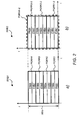
- a second radio resource block RRB2 covers the predefined frequency range PFR that contains the eight PRBs PRB1 to PRB8.
- the first PRB PRB1, the second PRB PRB2 and the third PRB PRB3 may be assigned for example to a further first predefined group of radio resources PGRR1-2,
- the fourth PRB PRB4, the fifth PRB PRB5, the sixth PRB PRB6 may be assigned for example to a further second predefined group of radio resources PGRR2-2.
- the seventh PRB PRB7 and the eighth PRB PRB8 may be assigned for example to a further third predefined group of radio resources PGRR3-2.
- Uplink signals of the uplink data are received at the first antenna system AS1-BS1 of the first base station BS1 as one or several first uplink signals and are provided from the second antenna system AS2-BS1 of the first base station BS1 to the first base station BS1 for decoding and data recovery.
- Uplink signals of the uplink data are received at the second antenna system AS1-BS2 of the first base station BS1 as one or several second uplink signals and are provided from the second antenna system AS2-BS1 of the first base station BS1 to the first base station BS3 for decoding and data recovery.
- the third network server NS3 may contain a third reception unit JRU3 for decoding and recovering uplink data that have been received via the third predefined group of radio resources PGRR3 (see Figure 2 ) by the fifth cooperation set of antenna systems CSAS5.
- the antenna systems AS1, AS2, AS3, AS4, AS5 and AS6 may contain one, two, four or more antenna elements in a same way or independently from each other and may be for example remote radio heads.
- the communication links CL2, CL3, CL4, CL5, CL6, CL7 and CL8 may be based on Ethernet links and the distribution network nodes DNN1, DNN2 and DNN3 may be Ethernet switches.
- the uplink data are received at the second antenna system AS2 as the second uplink signals and are provided from the second antenna system AS2 to the third network server NS3.
- the uplink data are received at the sixth antenna system AS6 as the third uplink signals and are provided from the sixth antenna system AS6 to the third network server NS3.
- the third network server NS3 may decode and recover the uplink data based on the received first uplink signals, based on the received second uplink signals and based on the received third uplink signals.
- the first network server NS1 determines one or more first radio resources of the third predefined group of radio resources PGRR3 for an uplink transmission of the uplink data from the first mobile station MS1 to the first antenna system AS1 via the first transmission path TP1 to the second antenna system AS2 via the second transmission path TP2 and to the sixth antenna system AS6 via the third transmission path TP3 and determines one or more second radio resources of the third predefined group of radio resources PGRR3 for an uplink transmission of the further uplink data from the second mobile station MS2 to the first antenna system AS1 via the fourth transmission path TP4, to the second antenna system AS2 via the fifth transmission path TP5 and to the sixth antenna system AS6 via the sixth transmission path TP6.
- no processing resources are required at the second network server NS2 or processing resources at the second network server NS2 may be applied for other radio cells of the radio access network RAN2.
- the first network node NN1 is the first base station BS1
- the second network node NN2 is the second base station BS2
- the third network node NN3 is not required.
- the steps M1/18-2, M1/19, M1/28, M1/30, M1/31, M1/32, M1/32-2, and M1/35 are performed by a single network node, which is the first base station BS1 and the steps M1/3, M1/21, M1/37 and M1/38 are not required.
- the first network node NN1 is the first network server NS1
- the second network node NN2 is the second network server NS2
- the third network node NN3 is the third network server NS3.
- the third allocation information ALOC-INFO3 also contains a mapping between predefined groups of radio resources and predefined group of antenna systems for which the third network node NN3 is responsible regarding the decoding of the received uplink signals and the recovery of the uplink data received via a respective predefined group of radio resources (see Table 1).
- the first network node NN1 may verify for example periodically, whether a CoMP transmission scheme for the uplink is suitable for one or several mobile stations such as the first mobile station MS1, which is/are located for example in the first radio cell C1. Therefore, the first network node NN1 may verify according to a first condition, whether a working load of for example the third predefined group of radio resources PGRR3 is above a predefined threshold such as 90 % of all radio resources of the third predefined group of radio resources PGRR3. In addition or alternatively, the first network node NN1 may verify according to a second condition, whether there exist(s) one mobile station or more mobile stations within the first radio cell C1, which transmit(s) currently with a maximum transmit power.
- the first network node NN1 may decide to perform the CoMP transmission scheme for the uplink transmission of for example the first mobile station MS1, if one or several of the above conditions are fulfilled. If the first network node NN1 may decide not to perform the CoMP transmission scheme for the uplink transmission for one of the mobile stations in the first radio cell C1, the method MET1 may be stopped and may be started again for example after a predefined time such as 5 ms, 50 ms, 100 ms, 500 ms or 1 s.
- the further load is mainly determined by a data rate, that is required to fulfil QoS requirements for the first mobile station MS1 and by a current radio link quality (a poor radio link quality requires more radio resources and more retransmissions with a higher load than a good radio link quality).
- the first network node NN1 may estimate a second load and preferably further transmission link loads on further transmission links between the network nodes or further network nodes (not shown in Figure 1 and Figure 4 for simplification) managing a further predefined group of antenna systems.
- the first network node NN1 may estimate first processing loads at network nodes of one of the predefined groups of antenna systems CSAS1, CSAS4, CSAS4, CSAS6 (see Figure 3 ).
- the first network node NN1 may estimate second processing loads and prefereably further processing loads at network nodes of one or several further predefined cooperation sets of antenna systems CSAS1, CSAS4, CSAS4, CSAS6 (see Figure 3 ).
- the first network node NN1 may select the fifth cooperation set of antenna systems CSAS5, for which the first load, the second load or one of the further transmission link loads is smallest or for which the first load, the second load or one of the further transmission link loads is below a first predefined load for having free transmission capacity on transmission links for potential further CoMP receptions of further uplink signals from further mobile stations or for which of the first load, the second load or one of the further transmission link loads no overload arises.
- a cooperation set of antenna systems and an assigned predefined group or radio resources may be selected in such a way, that a number of radio cells assigned to other network nodes than the network node, which may be responsible for the recovery of the uplink data, is minimized as already described above.
- the selection of the fifth cooperation set of antenna systems CSAS5 may be further based on a condition, that the processing loads of network nodes of the selected cooperation set of antenna systems are minimized or below predefined loads for being able to process uplink signals of potential further CoNP receptions from further mobile stations or that no overload at the network nodes arises.
- RSRP reference signal received power
- the first network node NN 1 may select a cooperation set of antenna systems and an assigned predefined group of radio resources for the first mobile station MS1, so that a network node responsible for the decoding of the received uplink signals and for the recovery of the uplink data of the first mobile station MS1 may be also a network node, which has most assigned antenna systems as part of the cooperation set of antenna systems (see Figure 3 a), d), e), f) ).
- the second network node NN2 may verify for example periodically, whether a CoMP transmission scheme for the uplink is suitable for one or several of further mobile stations such as the second mobile station MS2, which is/are located for example in the sixth radio cell C6.
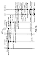
- the first network node NN 1 determines one or several first radio resources of the third predefined group of radio resources PGRR3. Thereby, the first network node NN1 automatically assigns the first mobile station MS1 to the fifth cooperation set of antenna systems CSAS5 for the uplink transmission of the uplink data from the first mobile station MS1 to the antenna system ANT-SYS1 and to the antenna system ANT-SYS2.
- the antenna system ANT-SYS1 is assigned to the first base station BS1 (see Figure 1 ) or to the first network server NS1 (see Figure 4 ).
- the antenna system ANT-SYS2 is assigned to the second base station BS2 (see Figure 1 ) or to the second network server NS2 (see Figure 4 ).
- the first network node NN1 transmits first reservation information RES-INFO1 to the first mobile station MS1, which receives the first reservation information RES-INFO1 in a further step M1/13.
- the first reservation information RES-INFO1 may be for example an uplink grant message such as applied in 3GPP LTE.
- the first reservation information RES-INFO1 may contain for example one identifier for a single PRB or several identifiers for several PRBs of the third predefined group of radio resources PGRR3.
- the second network node NN2 determines one or several second radio resources of the third predefined group of radio resources PGRR3. Thereby, the second network node NN2 automatically assigns the second mobile station MS2 also to the fifth cooperation set of antenna systems CSAS5 for the uplink transmission of the uplink data from the second mobile station MS2 to the antenna system ANT-SYS1 and to the antenna system ANT-SYS2.
- the second network node NN2 transmits second reservation information RES-INFO2 to the second mobile station MS2, which receives the second reservation information RES-INFO2 in a further step M1/16.
- the second reservation information RES-INF02 may be for example a further uplink grant message such as applied in 3GPP LTE.
- the second reservation information RES-INF02 may contain for example one identifier for a single PRB or several identifiers for several PRBs of the third predefined group of radio resources PGRR3.
- the first network node NN1 or the third network node NN3 may request a retransmission of the modulated and coded uplink data CM-UP-DATA1 -MS1.
- the second network node NN2 transmits second scheduling information SCHEDULE-INFO2 for the second mobile station MS2 to the first network node NN1 and to the third network node NN3, which receive the second scheduling information SCHEDULE-INFO2 in next steps M1/20 and M1/21.
- the second network node NN2 determines the corresponding third network node NN3 based on the third predefined group of radio resources PGRR3 in which the one or the several second radio resources, which have been determined in the step M1/14, fall into (see Table 1).
- the second network node NN2 transmits the second scheduling information SCHEDULE-INFO2 to all base stations of the fifth cooperation set of antenna systems CSAS5. This allows the receiving base stations to know which PRB(s) contain uplink data of the second mobile station MS and therefore should be forwarded to the first network node NN1 (see Figure 1 ) or to the third network node NN3 (see Figure 4 ).
- the second scheduling information SCHEDULE-INFO2 may contain for example the identifier for the single PRB or the several identifiers for the several PRBs of the third predefined group of radio resources PGRR3.
- the first mobile station MS1 further transmits the modulated and coded uplink data CM-UP-DATA-MS1 to the antenna system ANT-SYS2, which receive the modulated and coded uplink data CM-UP-DATA-MS1 in step M1/24 as second modulated and coded uplink signals CM-UP-DATA2-MS1.
- the second mobile station MS2 transmits the modulated and coded uplink data CM-UP-DATA-MS2 to the antenna system ANT-SYS2, which receive the modulated and coded uplink data CM-UP-DATA-MS2 as further second modulated and coded uplink signals CM-UP-DATA2-MS2 during the step M1/24.
- the predefined criterion is compared with the SINR measurement value. If the SINR measurement value is equal or larger than the predefined criterion such as an SINR threshold value, the method MET1 may be continued with a further step M1/27. If the SINR measurement value is smaller than the SINR threshold value, the first and the further first modulated and coded uplink signals CM-UP-DATA1-MS1, CM-UP-DATA-MS2 are not forwarded to the second network node NN2 or the third network node NN3 and the method MET1 may be continued by step M1/31 without data from the antenna system ANT-SYS1.
- the predefined criterion such as an SINR threshold value
- the antenna system ANT-SYS1 transmits the first and the further first modulated and coded uplink signals CM-UP-DATA1-MS1, CM-UP-DATA1-MS2 automatically without a verification or based on the verification as described above to the first network node NN1 (see Figure 1 ) or the third network node NN3 (see Figure 4 ), which receives the first and the further first modulated and coded uplink signals CM-UP-DATA1-MS1, CM-UP-DATA1-MS2 in a next step M1/28.
- the second and the further second modulated and coded uplink signals CM-UP-DATA2-MS1, CM-UP-DATA2-MS2 are not forwarded to the first network node NN1 or the third network node NN3 and the method MET1 may be continued by step M1/31 without data from the antenna system ANT-SYS2.
- the error report ERROR-REP may contain an indication for one PRB or indications for several PRBs, which are known to the first network node NN1 or the third network node NN3 by the reception of the first scheduling information SCHEDULE-INFO1, that uplink data contained in this PRB or these PRBs could not be recovered error-free by the first network node NN1 or the third network node NN3.
- the first network node NN1 or the third network node NN3 preferably transmits second optimization information OPTIMIZ-INF02 to the second network node NN2, which receives the second optimization information OPTIMIZ-INFO2 in a next step M1/38.
- the second optimization information OPTIMIZ-INFO2 contains for example channel state information of the uplink transmission from the second mobile station MS2 to the antenna system ANT-SYS2 and preferably to the antenna system ANT-SYS1.
- the second optimization information OPTIMIZ-INF02 may be transmitted during the step M1/32 in parallel to the uplink data UP-DATA-MS2 or the error report ERROR-REP.
- FIG. 7 two block diagrams of second network nodes NN2-1, NN2-2 are shown.
- the second network nodes NN2-1, NN2-2 relate to the second network node NN2 shown in Figure 5 .
- the second network node NN2-1 may receive via the external connector NN2-CON1 and the transceiver NN2-TR1 the second allocation information ALOC-INF02, the first scheduling information SCHEDULE-INFO1, the uplink data UP-DATA-MS2 and the second optimization information OPTIMIZ-INF02.
- the second network node NN2-1 further contains a further transceiver NN2-TR2 and a further external connector NN2-CON2.
- the further external connector NN2-CON2 may be adapted to connect the antenna system ANT-SYS2 (as shown in Figure 7 ).
- the further transceiver NN2-TR2 may be a radio transceiver and may contain the second scheduling unit SU2 and the second reception unit JRU2 and is used for example to transmit the second reservation information RES-INFO2.
Landscapes
- Engineering & Computer Science (AREA)
- Computer Networks & Wireless Communication (AREA)
- Signal Processing (AREA)
- Mobile Radio Communication Systems (AREA)
Priority Applications (2)
| Application Number | Priority Date | Filing Date | Title |
|---|---|---|---|
| EP12305029.6A EP2615744A1 (de) | 2012-01-10 | 2012-01-10 | Verfahren zur Übertragung von Uplink-Daten, erster Netzwerkknoten und zweiter Netzwerkknoten dafür |
| PCT/EP2012/070846 WO2013104442A1 (en) | 2012-01-10 | 2012-10-22 | Method for transmitting uplink data, first network node, and second network node thereof |
Applications Claiming Priority (1)
| Application Number | Priority Date | Filing Date | Title |
|---|---|---|---|
| EP12305029.6A EP2615744A1 (de) | 2012-01-10 | 2012-01-10 | Verfahren zur Übertragung von Uplink-Daten, erster Netzwerkknoten und zweiter Netzwerkknoten dafür |
Publications (1)
| Publication Number | Publication Date |
|---|---|
| EP2615744A1 true EP2615744A1 (de) | 2013-07-17 |
Family
ID=47040748
Family Applications (1)
| Application Number | Title | Priority Date | Filing Date |
|---|---|---|---|
| EP12305029.6A Withdrawn EP2615744A1 (de) | 2012-01-10 | 2012-01-10 | Verfahren zur Übertragung von Uplink-Daten, erster Netzwerkknoten und zweiter Netzwerkknoten dafür |
Country Status (2)
| Country | Link |
|---|---|
| EP (1) | EP2615744A1 (de) |
| WO (1) | WO2013104442A1 (de) |
Cited By (1)
| Publication number | Priority date | Publication date | Assignee | Title |
|---|---|---|---|---|
| WO2015027522A1 (zh) * | 2013-09-02 | 2015-03-05 | 华为技术有限公司 | 一种上行协作发射方法及设备 |
Families Citing this family (2)
| Publication number | Priority date | Publication date | Assignee | Title |
|---|---|---|---|---|
| US10673729B2 (en) | 2013-11-29 | 2020-06-02 | Telefonaktiebolaget Lm Ericsson (Publ) | Control of cellular network operation using interference-based metric |
| US10567179B1 (en) * | 2018-08-31 | 2020-02-18 | Nxp B.V. | Network device and method for performing network operations in a communications network |
Citations (3)
| Publication number | Priority date | Publication date | Assignee | Title |
|---|---|---|---|---|
| US20100157901A1 (en) * | 2007-06-18 | 2010-06-24 | Sanderovitz Amichay | Wireless network architecture and method for base station utilization |
| US20110263271A1 (en) * | 2008-09-26 | 2011-10-27 | Christian Hoymann | Techniques for Uplink Cooperation of Access Nodes |
| US20110268007A1 (en) * | 2009-10-26 | 2011-11-03 | Qualcomm Incorporated | COORDINATED MULTI-POINT (CoMP) NETWORK AND PROTOCOL ARCHITECTURE |
-
2012
- 2012-01-10 EP EP12305029.6A patent/EP2615744A1/de not_active Withdrawn
- 2012-10-22 WO PCT/EP2012/070846 patent/WO2013104442A1/en not_active Ceased
Patent Citations (3)
| Publication number | Priority date | Publication date | Assignee | Title |
|---|---|---|---|---|
| US20100157901A1 (en) * | 2007-06-18 | 2010-06-24 | Sanderovitz Amichay | Wireless network architecture and method for base station utilization |
| US20110263271A1 (en) * | 2008-09-26 | 2011-10-27 | Christian Hoymann | Techniques for Uplink Cooperation of Access Nodes |
| US20110268007A1 (en) * | 2009-10-26 | 2011-11-03 | Qualcomm Incorporated | COORDINATED MULTI-POINT (CoMP) NETWORK AND PROTOCOL ARCHITECTURE |
Cited By (1)
| Publication number | Priority date | Publication date | Assignee | Title |
|---|---|---|---|---|
| WO2015027522A1 (zh) * | 2013-09-02 | 2015-03-05 | 华为技术有限公司 | 一种上行协作发射方法及设备 |
Also Published As
| Publication number | Publication date |
|---|---|
| WO2013104442A1 (en) | 2013-07-18 |
Similar Documents
| Publication | Publication Date | Title |
|---|---|---|
| US11212820B2 (en) | Inter-cell fractional frequency reuse scheduler | |
| US10116406B2 (en) | Method and apparatus for reducing inter-cell interference | |
| CN110999529B (zh) | 用于经由多层隧道传送和集中控制在多跳无线网络中进行转发的技术和装置 | |
| EP2816833B1 (de) | Funkressourcensteuerung für Dual-Access-Technology-Zellen | |
| US10299223B2 (en) | System and method to facilitate power domain interference coordination in a network environment | |
| US20110255436A1 (en) | Method of Optimizing Comp Zone for Joint Processing Mode | |
| US11871439B2 (en) | Inter-cell fractional frequency reuse scheduler | |
| JP2018504030A (ja) | 無線アクセスへのネットワーク機能の柔軟な割り当て | |
| EP3437244B1 (de) | Verfahren, system und vorrichtungen zur aktivierung eines netzknotens zur durchführung einer funkbetriebsaufgabe in einem telekommunikationsnetz | |
| CN107809770B (zh) | 传输数据的方法、基站和用户设备 | |
| Tseliou et al. | Resources negotiation for network virtualization in LTE-A networks | |
| EP2615744A1 (de) | Verfahren zur Übertragung von Uplink-Daten, erster Netzwerkknoten und zweiter Netzwerkknoten dafür | |
| CN110167166B (zh) | 一种基站、用户设备中的用于无线通信的方法和装置 | |
| KR20120064937A (ko) | 무선 통신 시스템에서 기지국의 자원 운용 방법 및 장치 | |
| Narmanlioglu et al. | Interference coordination in SDN-based heterogeneous mobile networks | |
| US12289714B2 (en) | Network node, user equipment and methods performed therein in a wireless communications network | |
| WO2025065309A1 (en) | Designated device selection for grouped user equipments | |
| US9882676B2 (en) | Link-adaptation in partly centralized radio access networks | |
| TW201336256A (zh) | 傳輸上行鏈路資料之方法及其第一網路節點及第二網路節點 | |
| Alsabri | Strategies for Implementing LTE/LTE-A Wireless Networks | |
| Holland et al. | Management architecture for aggregation of heterogeneous systems and spectrum bands | |
| WO2025072306A1 (en) | Systems and methods for resource allocation chain construction and advance planning time calculation in cell-free networks | |
| CN102428721B (zh) | 中继网络资源重用的方法以及相应的基站 | |
| Pedersen | Hua Wang, Claudio Rosa & Klaus |
Legal Events
| Date | Code | Title | Description |
|---|---|---|---|
| PUAI | Public reference made under article 153(3) epc to a published international application that has entered the european phase |
Free format text: ORIGINAL CODE: 0009012 |
|
| 17P | Request for examination filed |
Effective date: 20121016 |
|
| AK | Designated contracting states |
Kind code of ref document: A1 Designated state(s): AL AT BE BG CH CY CZ DE DK EE ES FI FR GB GR HR HU IE IS IT LI LT LU LV MC MK MT NL NO PL PT RO RS SE SI SK SM TR |
|
| AX | Request for extension of the european patent |
Extension state: BA ME |
|
| RBV | Designated contracting states (corrected) |
Designated state(s): AL AT BE BG CH CY CZ DE DK EE ES FI FR GB GR HR HU IE IS IT LI LT LU LV MC MK MT NL NO PL PT RO RS SE SI SK SM TR |
|
| RAP1 | Party data changed (applicant data changed or rights of an application transferred) |
Owner name: ALCATEL LUCENT |
|
| STAA | Information on the status of an ep patent application or granted ep patent |
Free format text: STATUS: THE APPLICATION IS DEEMED TO BE WITHDRAWN |
|
| 18D | Application deemed to be withdrawn |
Effective date: 20160802 |