EP2615665A2 - Separator, production method for same and electrochemical device equipped with same - Google Patents
Separator, production method for same and electrochemical device equipped with same Download PDFInfo
- Publication number
- EP2615665A2 EP2615665A2 EP11823754.4A EP11823754A EP2615665A2 EP 2615665 A2 EP2615665 A2 EP 2615665A2 EP 11823754 A EP11823754 A EP 11823754A EP 2615665 A2 EP2615665 A2 EP 2615665A2
- Authority
- EP
- European Patent Office
- Prior art keywords
- separator
- compound
- acyl halide
- multifunctional
- porous substrate
- Prior art date
- Legal status (The legal status is an assumption and is not a legal conclusion. Google has not performed a legal analysis and makes no representation as to the accuracy of the status listed.)
- Granted
Links
Images




Classifications
-
- H—ELECTRICITY
- H01—ELECTRIC ELEMENTS
- H01M—PROCESSES OR MEANS, e.g. BATTERIES, FOR THE DIRECT CONVERSION OF CHEMICAL ENERGY INTO ELECTRICAL ENERGY
- H01M50/00—Constructional details or processes of manufacture of the non-active parts of electrochemical cells other than fuel cells, e.g. hybrid cells
- H01M50/40—Separators; Membranes; Diaphragms; Spacing elements inside cells
- H01M50/409—Separators, membranes or diaphragms characterised by the material
- H01M50/411—Organic material
- H01M50/414—Synthetic resins, e.g. thermoplastics or thermosetting resins
- H01M50/423—Polyamide resins
-
- H—ELECTRICITY
- H01—ELECTRIC ELEMENTS
- H01M—PROCESSES OR MEANS, e.g. BATTERIES, FOR THE DIRECT CONVERSION OF CHEMICAL ENERGY INTO ELECTRICAL ENERGY
- H01M50/00—Constructional details or processes of manufacture of the non-active parts of electrochemical cells other than fuel cells, e.g. hybrid cells
- H01M50/40—Separators; Membranes; Diaphragms; Spacing elements inside cells
- H01M50/403—Manufacturing processes of separators, membranes or diaphragms
-
- H—ELECTRICITY
- H01—ELECTRIC ELEMENTS
- H01M—PROCESSES OR MEANS, e.g. BATTERIES, FOR THE DIRECT CONVERSION OF CHEMICAL ENERGY INTO ELECTRICAL ENERGY
- H01M10/00—Secondary cells; Manufacture thereof
- H01M10/05—Accumulators with non-aqueous electrolyte
- H01M10/052—Li-accumulators
-
- H—ELECTRICITY
- H01—ELECTRIC ELEMENTS
- H01M—PROCESSES OR MEANS, e.g. BATTERIES, FOR THE DIRECT CONVERSION OF CHEMICAL ENERGY INTO ELECTRICAL ENERGY
- H01M50/00—Constructional details or processes of manufacture of the non-active parts of electrochemical cells other than fuel cells, e.g. hybrid cells
- H01M50/40—Separators; Membranes; Diaphragms; Spacing elements inside cells
- H01M50/409—Separators, membranes or diaphragms characterised by the material
- H01M50/411—Organic material
- H01M50/414—Synthetic resins, e.g. thermoplastics or thermosetting resins
-
- H—ELECTRICITY
- H01—ELECTRIC ELEMENTS
- H01M—PROCESSES OR MEANS, e.g. BATTERIES, FOR THE DIRECT CONVERSION OF CHEMICAL ENERGY INTO ELECTRICAL ENERGY
- H01M50/00—Constructional details or processes of manufacture of the non-active parts of electrochemical cells other than fuel cells, e.g. hybrid cells
- H01M50/40—Separators; Membranes; Diaphragms; Spacing elements inside cells
- H01M50/409—Separators, membranes or diaphragms characterised by the material
- H01M50/411—Organic material
- H01M50/414—Synthetic resins, e.g. thermoplastics or thermosetting resins
- H01M50/417—Polyolefins
-
- H—ELECTRICITY
- H01—ELECTRIC ELEMENTS
- H01M—PROCESSES OR MEANS, e.g. BATTERIES, FOR THE DIRECT CONVERSION OF CHEMICAL ENERGY INTO ELECTRICAL ENERGY
- H01M50/00—Constructional details or processes of manufacture of the non-active parts of electrochemical cells other than fuel cells, e.g. hybrid cells
- H01M50/40—Separators; Membranes; Diaphragms; Spacing elements inside cells
- H01M50/409—Separators, membranes or diaphragms characterised by the material
- H01M50/449—Separators, membranes or diaphragms characterised by the material having a layered structure
-
- H—ELECTRICITY
- H01—ELECTRIC ELEMENTS
- H01M—PROCESSES OR MEANS, e.g. BATTERIES, FOR THE DIRECT CONVERSION OF CHEMICAL ENERGY INTO ELECTRICAL ENERGY
- H01M50/00—Constructional details or processes of manufacture of the non-active parts of electrochemical cells other than fuel cells, e.g. hybrid cells
- H01M50/40—Separators; Membranes; Diaphragms; Spacing elements inside cells
- H01M50/409—Separators, membranes or diaphragms characterised by the material
- H01M50/449—Separators, membranes or diaphragms characterised by the material having a layered structure
- H01M50/451—Separators, membranes or diaphragms characterised by the material having a layered structure comprising layers of only organic material and layers containing inorganic material
-
- H—ELECTRICITY
- H01—ELECTRIC ELEMENTS
- H01M—PROCESSES OR MEANS, e.g. BATTERIES, FOR THE DIRECT CONVERSION OF CHEMICAL ENERGY INTO ELECTRICAL ENERGY
- H01M50/00—Constructional details or processes of manufacture of the non-active parts of electrochemical cells other than fuel cells, e.g. hybrid cells
- H01M50/40—Separators; Membranes; Diaphragms; Spacing elements inside cells
- H01M50/409—Separators, membranes or diaphragms characterised by the material
- H01M50/449—Separators, membranes or diaphragms characterised by the material having a layered structure
- H01M50/457—Separators, membranes or diaphragms characterised by the material having a layered structure comprising three or more layers
-
- H—ELECTRICITY
- H01—ELECTRIC ELEMENTS
- H01M—PROCESSES OR MEANS, e.g. BATTERIES, FOR THE DIRECT CONVERSION OF CHEMICAL ENERGY INTO ELECTRICAL ENERGY
- H01M50/00—Constructional details or processes of manufacture of the non-active parts of electrochemical cells other than fuel cells, e.g. hybrid cells
- H01M50/40—Separators; Membranes; Diaphragms; Spacing elements inside cells
- H01M50/489—Separators, membranes, diaphragms or spacing elements inside the cells, characterised by their physical properties, e.g. swelling degree, hydrophilicity or shut down properties
-
- H—ELECTRICITY
- H01—ELECTRIC ELEMENTS
- H01M—PROCESSES OR MEANS, e.g. BATTERIES, FOR THE DIRECT CONVERSION OF CHEMICAL ENERGY INTO ELECTRICAL ENERGY
- H01M50/00—Constructional details or processes of manufacture of the non-active parts of electrochemical cells other than fuel cells, e.g. hybrid cells
- H01M50/40—Separators; Membranes; Diaphragms; Spacing elements inside cells
- H01M50/489—Separators, membranes, diaphragms or spacing elements inside the cells, characterised by their physical properties, e.g. swelling degree, hydrophilicity or shut down properties
- H01M50/491—Porosity
-
- Y—GENERAL TAGGING OF NEW TECHNOLOGICAL DEVELOPMENTS; GENERAL TAGGING OF CROSS-SECTIONAL TECHNOLOGIES SPANNING OVER SEVERAL SECTIONS OF THE IPC; TECHNICAL SUBJECTS COVERED BY FORMER USPC CROSS-REFERENCE ART COLLECTIONS [XRACs] AND DIGESTS
- Y02—TECHNOLOGIES OR APPLICATIONS FOR MITIGATION OR ADAPTATION AGAINST CLIMATE CHANGE
- Y02E—REDUCTION OF GREENHOUSE GAS [GHG] EMISSIONS, RELATED TO ENERGY GENERATION, TRANSMISSION OR DISTRIBUTION
- Y02E60/00—Enabling technologies; Technologies with a potential or indirect contribution to GHG emissions mitigation
- Y02E60/10—Energy storage using batteries
-
- Y—GENERAL TAGGING OF NEW TECHNOLOGICAL DEVELOPMENTS; GENERAL TAGGING OF CROSS-SECTIONAL TECHNOLOGIES SPANNING OVER SEVERAL SECTIONS OF THE IPC; TECHNICAL SUBJECTS COVERED BY FORMER USPC CROSS-REFERENCE ART COLLECTIONS [XRACs] AND DIGESTS
- Y02—TECHNOLOGIES OR APPLICATIONS FOR MITIGATION OR ADAPTATION AGAINST CLIMATE CHANGE
- Y02P—CLIMATE CHANGE MITIGATION TECHNOLOGIES IN THE PRODUCTION OR PROCESSING OF GOODS
- Y02P70/00—Climate change mitigation technologies in the production process for final industrial or consumer products
- Y02P70/50—Manufacturing or production processes characterised by the final manufactured product
Definitions
- the present invention relates to a separator for an electrochemical device, a manufacturing method thereof, and an electrochemical device comprising the same.
- lithium secondary batteries developed in the early 1990's have drawn attention for their higher operating voltage and much higher energy density than those of conventional batteries using an aqueous electrolyte such as Ni-MH batteries, Ni-Cd batteries, and H 2 SO 4 -Pb batteries.
- lithium secondary batteries have shortcomings such as a complicate manufacturing process and safety-related problems caused by the use of an organic electrolyte, for example, firing, explosion, and the like.
- Lithium-ion polymer batteries that have settled the drawbacks of lithium ion batteries are considered as one of the next-generation batteries.
- lithium-ion polymer batteries have a relatively lower battery capacity than lithium ion batteries, and in particular, have an insufficient discharging capacity at low temperature. Accordingly, there is an urgent need to solve these disadvantages of lithium-ion polymer batteries.
- electrochemical devices are being produced from many different companies, and they all exhibit different safety characteristics. Thus, it is important to evaluate and ensure the safety of electrochemical devices. The most important factor to consider is that electrochemical devices should not cause any damage to users due to malfunction. Taking this into account, Safety Regulations strictly prohibit safety-related accidents of electrochemical devices such as firing or smoke emission. According to the safety characteristics of electrochemical devices, thermal runaway caused by overheating of an electrochemical device or puncture of a separator may increase the risk of explosion.
- a polyolefin-based porous membrane conventionally used as a separator for an electrochemical device may show severe thermal shrinkage behaviors when the electrochemical device is subject to thermal runaway, thereby resulting in a short circuit between a cathode and an anode.
- a conventional separator such as a polyolefin-based porous membrane has poor wettability to an electrolyte, which may have a negative influence on improving the performance of an electrochemical device.
- a separator including a plate-like porous substrate, and a porous thin-film coating layer formed on at least one surface of the plate-like porous substrate and containing crosslinked polyamide prepared by polymerizing a multifunctional amine compound having at least two amine groups with a multifunctional acyl halide compound of an aromatic compound having at least two acyl halide groups.
- a method for manufacturing the above-mentioned separator including preparing a first solution by dissolving a multifunctional amine compound having at least two amine groups in water and a second solution by dissolving a multifunctional acyl halide compound of an aromatic compound having at least two acyl halide groups in an organic solvent, and applying the first solution and the second solution on at least one surface of a plate-like porous substrate in a sequential manner, followed by interfacial polymerization.
- the crosslinked polyamide thin-film coating layer formed on the porous substrate has a very small thickness and a high porosity, and thus hardly affects the air permeability of the separator. Also, the crosslinked polyamide thin-film coating layer has good hydrophilicity and wettability to an electrolyte as intrinsic characteristics of amide, and thus may improve the performance of the electrochemical device. Also, the crosslinked polyamide thin-film coating layer has excellent resistance to heat and deformation, and thus may prevent the thermal shrinkage of the separator.
- a separator of the present invention may have a plate-like porous substrate.
- the plate-like porous substrate is not particularly limited if it is a conventional one used in an electrochemical device, and may be, for example, a porous membrane or non-woven fabric made from various polymers.
- a polyolefin-based porous membrane or a non-woven fabric made from polyethylene teraphthalate fibers that is used in an electrochemical device, particularly as a separator for an electrochemical device may be used.
- its material or shape may be variously selected depending on the purpose.
- the thickness of the plate-like porous substrate is not particularly limited, however is preferably 1 to 100 ⁇ m, more preferably 5 to 50 ⁇ m. Also, the pore size and the porosity of the porous substrate are not particularly limited, however are preferably 0.01 to 50 ⁇ m and 10 to 95 %, respectively.
- the separator of the present invention may have a porous thin-film coating layer containing crosslinked polyamide formed on the plate-like porous substrate, the crosslinked polyamide prepared by polymerizing a multifunctional amine compound having at least two amine groups with a multifunctional acyl halide compound of an aromatic compound having at least two acyl halide groups.
- the porous thin-film coating layer containing the crosslinked polyamide may be formed on one surface or both surfaces of the plate-like porous substrate.
- the porous thin-film coating layer containing the crosslinked polyamide has a very small thickness and a high porosity so as not to influence the air permeability of the plate-like porous substrate, and so the entire separator has excellent air permeability.
- the porous thin-film coating layer containing the crosslinked polyamide may preferably have a thickness of 0.1 to 1 ⁇ m.
- the multifunctional acyl halide compound in the second solution may preferably include trimezoyl chloride, isophthaloyl chloride, and terephthaloyl chloride.
- the organic solvent of the second solution may include hexane, cyclohexane, heptane, C 8 to C 12 alkanes, dichlorodifluoromethane, trichlorofluoromethane, chlorodifluoromethane, dichlorotetrafluoroethane, and trichlorotrifluoroethane.
- the first and second solutions may be coated on at least one surface of the plate-like porous substrate in a sequential manner, followed by interfacial polymerization, to form a porous thin-film coating layer containing crosslinked polyamide.
- the separator of the present invention may be interposed between a cathode and an anode to fabricate an electrochemical device.
- the polymer used may form a gel by the reaction with an electrolyte injected after the battery assembly using the separator.
- the separator of the present invention is applied to a battery by winding, however may be applied to a battery by lamination or stacking, folding, and the like.
- an electrode assembly 100 may be manufactured by placing a separator 70 of the present invention between a cathode 10 and an anode 20, each coated with an active material, and then winding the cathode 10, the separator 70, and the anode 20 in a continuous manner.
- an electrode assembly 200 may be manufactured by bending the cathode 10, the separator 70, and the anode 20 in a zigzag fashion at regular intervals. In the electrode assembly manufactured by winding or bending, a plurality of electrodes and a plurality of separators may be alternately stacked for capacity improvement.
- the electrode assembly may be manufactured by assembling a plurality of unit cells having a full cell or bi-cell structure on a folding film.
- the folding film may be a typical insulated film or the separator of the present invention.
- the full cell structure may have at least one cell comprising electrodes having opposite polarity and a separator interposed therebetween, in which the outmost electrodes have opposite polarity.
- a cathode/separator/anode or a cathode/separator/anode/separator/cathode/separator/anode may be mentioned as shown in FIGS. 4 and 5 .
- the bi-cell structure may have at least one cell comprising electrodes having opposite polarity and a separator interposed therebetween, in which the outmost electrodes have the same polarity.
- a cathode/separator/anode/separator/cathode or an anode/separator/cathode/separator/anode may be mentioned as shown in FIGS. 6 and 7 .
- the intervals between the unit cells and the polarity of the outmost electrode in each of the unit cells may be selected such that an electrode located on and in contact with the folding film and an electrode located under and in contact with the folding film are opposite in polarity.
- the intervals between the unit cells and the polarity of the outmost electrode in each of the unit cells may be selected such that the electrode assembly has the structure of cathode/separator/anode/folding film/cathode/separator/anode/folding film/cathode ...
- a plurality of unit cells may be arranged at a predetermined interval on one surface of a folding film extending in a lengthwise direction, and the arranged unit cells and the folding film may be bent in a zigzag fashion.
- the resulting electrode assembly may be such that the unit cells are inserted in the bent and stacked folding film.
- a plurality of unit cells may be arranged at a predetermined interval on both surfaces of a folding film extending in a lengthwise direction, and the arranged unit cells and the folding film may be bent in a zigzag fashion.
- the resulting electrode assembly may be such that the unit cells are inserted in the bent and stacked folding film.
- the intervals between the unit cells and the polarity of the outmost electrode in each of the unit cells may be selected such that an electrode located on and in contact with the folding film and an electrode located under and in contact with the folding film are opposite in polarity.
- the intervals between the unit cells and the polarity of the outmost electrode in each of the unit cells may be selected such that the electrode assembly has the structure of cathode/separator/anode/folding film/cathode/separator/anode/folding film/cathode ...
- Electrodes may be arranged on one surface of a folding film in an alternate order of, for example, an anode, a cathode, an anode, a cathode ..., and the arranged electrodes and the folding film may be wound in one direction.
- the resulting electrode assembly may be such that the electrodes are inserted in the wound folding film.
- a plurality of electrodes may be arranged at a predetermined interval on both surfaces of a folding film extending in a lengthwise direction, and the arranged electrodes and the folding film may be wound in one direction.
- the resulting electrode assembly may be such that the electrodes are inserted in the wound folding film.
- the intervals and polarity of the electrodes may be selected such that an electrode located on and in contact with the folding film and an electrode located under and in contact with the folding film are opposite in polarity.
- the intervals and polarity of the electrodes may be selected to manufacture an electrode assembly of cathode/folding film/anode/folding film/cathode...
- electrodes may be arranged on one surface of a folding film in an alternate order of, for example, an anode, a cathode, an anode, a cathode ..., and the arranged electrodes and the folding film may be bent in one direction.
- the resulting electrode assembly may be such that the electrodes are inserted in the bent and stacked folding film.
- a plurality of electrodes may be arranged at a predetermined interval on both surfaces of a folding film extending in a lengthwise direction, and the arranged electrodes and the folding film may be bent.
- the resulting electrode assembly may be such that the electrodes are inserted in the bent and stacked folding film.
- the intervals and polarity of the electrodes may be selected such that an electrode located on and in contact with the folding film and an electrode located under and in contact with the folding film are opposite in polarity.
- the intervals and polarity of the electrodes may be selected to manufacture an electrode assembly of cathode/folding film/anode/folding film/cathode ...
- the length of the folding film used in manufacturing the electrode assembly may be selected such that the folding film can surround the electrode assembly at least once after the last cell or electrode is placed in the above manner.
- the electrode assembly is not limited in this regard, and may be modified in various types.
- Comparative Example 1 Triple-layered separator for a lithium ion battery
- a triple-layered separator for a lithium secondary battery composed of PP (polypropylene)/PE (polyethylene)/PP (polypropylene) was prepared.
- the separator had a thickness of 20 ⁇ m, a porosity of 40 %, and a pore size of 0.03 ⁇ m.
- Example 1 Polyamide-coated triple-layered separator for a lithium ion battery
- the triple-layered separator of comparative example 1 was dipped in the aqueous solution of 2 w% of metaphenyldiamine for 2 minutes, and the remaining water was then removed by means of rollers.
- the treated triple-layered separator was dipped in the solution of isoparaffin and 0.1 w% of trimezoyl chloride at room temperature for 1 minute.
- Test Example 1 Measurement of air permeability
- the comparative example 1 and example 1 were measured for air permeability, and the results are shown in Table 1 below. [Table 1] Air permeability (sec/100Ml) Comparative example 1 440 Example 1 420
- Test Example 3 Test for wettability
- the comparative example 1 showed that the movement distance of the electrolyte after the lapse of 30 minutes was 2 mm, and the example 1 having a polyamide coating layer showed that the movement distance of the electrolyte after the lapse of 30 minutes was 22 mm.
- the example 1 has excellent wettability to an electrolyte.
- Test Example 4 Test for charging performance
- a lithium secondary battery was fabricated by placing an anode (a copper foil coated with natural graphite) and a cathode (lithium metal) with the separator of comparative example 1 or example 1 interposed therebetween, and inserting 1M LiPF 6 EC/EMC electrolyte. Next, the battery was tested for charging performance, and the results are shown in FIG. 15 .
Landscapes
- Chemical & Material Sciences (AREA)
- Chemical Kinetics & Catalysis (AREA)
- Electrochemistry (AREA)
- General Chemical & Material Sciences (AREA)
- Engineering & Computer Science (AREA)
- Manufacturing & Machinery (AREA)
- Inorganic Chemistry (AREA)
- Cell Separators (AREA)
- Secondary Cells (AREA)
- Electric Double-Layer Capacitors Or The Like (AREA)
Abstract
Description
- This application claims priorities to Korean Patent Application No.
10-2010-0087091, filed on September 6, 2010 - In addition, this application claims priorities to Korean Patent Application No.
10-2011-0090097 filed on September 6, 2011 - The present invention relates to a separator for an electrochemical device, a manufacturing method thereof, and an electrochemical device comprising the same.
- Recently, there is an increasing interest in energy storage technologies. As the application fields of energy storage technologies have been extended to mobile phones, camcorders, notebook computers, and even electric cars, efforts towards the research and development on electrochemical devices have been increasing. In aspect of the above situation, rechargeable secondary batteries are at the center of attention as the most favorable electrochemical device. Lately, many studies have been done to design new electrodes and batteries to improve the capacity density and specific energy of the batteries.
- Among currently available secondary batteries, lithium secondary batteries developed in the early 1990's have drawn attention for their higher operating voltage and much higher energy density than those of conventional batteries using an aqueous electrolyte such as Ni-MH batteries, Ni-Cd batteries, and H2SO4-Pb batteries. However, lithium secondary batteries have shortcomings such as a complicate manufacturing process and safety-related problems caused by the use of an organic electrolyte, for example, firing, explosion, and the like. Lithium-ion polymer batteries that have settled the drawbacks of lithium ion batteries are considered as one of the next-generation batteries. However, lithium-ion polymer batteries have a relatively lower battery capacity than lithium ion batteries, and in particular, have an insufficient discharging capacity at low temperature. Accordingly, there is an urgent need to solve these disadvantages of lithium-ion polymer batteries.
- A variety of electrochemical devices are being produced from many different companies, and they all exhibit different safety characteristics. Thus, it is important to evaluate and ensure the safety of electrochemical devices. The most important factor to consider is that electrochemical devices should not cause any damage to users due to malfunction. Taking this into account, Safety Regulations strictly prohibit safety-related accidents of electrochemical devices such as firing or smoke emission. According to the safety characteristics of electrochemical devices, thermal runaway caused by overheating of an electrochemical device or puncture of a separator may increase the risk of explosion.
- In particular, a polyolefin-based porous membrane conventionally used as a separator for an electrochemical device may show severe thermal shrinkage behaviors when the electrochemical device is subject to thermal runaway, thereby resulting in a short circuit between a cathode and an anode. Meanwhile, a conventional separator such as a polyolefin-based porous membrane has poor wettability to an electrolyte, which may have a negative influence on improving the performance of an electrochemical device.
- Accordingly, there is a need for a separator with excellent heat resistance and wettability to an electrolyte.
- Therefore, it is an object of the invention to provide a separator having improved heat resistance and wettability to an electrolyte that can replace a conventional separator, a manufacturing method thereof, and an electrochemical device comprising the same.
- In an aspect of the present invention, there is provided a separator including a plate-like porous substrate, and a porous thin-film coating layer formed on at least one surface of the plate-like porous substrate and containing crosslinked polyamide prepared by polymerizing a multifunctional amine compound having at least two amine groups with a multifunctional acyl halide compound of an aromatic compound having at least two acyl halide groups.
- In another aspect of the present invention, there is provided a method for manufacturing the above-mentioned separator, including preparing a first solution by dissolving a multifunctional amine compound having at least two amine groups in water and a second solution by dissolving a multifunctional acyl halide compound of an aromatic compound having at least two acyl halide groups in an organic solvent, and applying the first solution and the second solution on at least one surface of a plate-like porous substrate in a sequential manner, followed by interfacial polymerization.
- The crosslinked polyamide thin-film coating layer formed on the porous substrate has a very small thickness and a high porosity, and thus hardly affects the air permeability of the separator. Also, the crosslinked polyamide thin-film coating layer has good hydrophilicity and wettability to an electrolyte as intrinsic characteristics of amide, and thus may improve the performance of the electrochemical device. Also, the crosslinked polyamide thin-film coating layer has excellent resistance to heat and deformation, and thus may prevent the thermal shrinkage of the separator.
- The accompanying drawings illustrate preferred embodiments of the present disclosure and, together with the foregoing disclosure, serve to provide further understanding of the technical spirit of the present disclosure. However, the present disclosure is not to be construed as being limited to the drawings.
-
FIG. 1 is a cross-sectional view illustrating a jelly roll-type electrode assembly according to a preferred embodiment of the present invention. -
FIG. 2 is a cross-sectional view illustrating an electrode assembly with a zigzag-bent separator according to a preferred embodiment of the present invention. -
FIG. 3 is a cross-sectional view illustrating a stack-type electrode assembly according to a preferred embodiment of the present invention. -
FIG. 4 is a cross-sectional view illustrating a full cell according to a preferred embodiment of the present invention. -
FIG. 5 is a cross-sectional view illustrating a full cell according to another preferred embodiment of the present invention. -
FIG. 6 is a cross-sectional view illustrating a bi-cell according to a preferred embodiment of the present invention. -
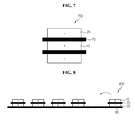
FIG. 7 is a cross-sectional view illustrating a bi-cell according to another preferred embodiment of the present invention. -
FIG. 8 is a cross-sectional view illustrating the winding of a stack/folding-type electrode assembly according to a preferred embodiment of the present invention. -
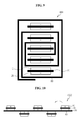
FIG. 9 is a cross-sectional view illustrating a stack/folding-type electrode assembly according to a preferred embodiment of the present invention. -
FIG. 10 is a cross-sectional view illustrating the winding of a double-sided stack/folding-type electrode assembly according to a preferred embodiment of the present invention. -
FIG. 11 is a cross-sectional view illustrating an electrode assembly with a bent folding film according to a preferred embodiment of the present invention. -
FIG. 12 is a cross-sectional view illustrating a double-sided electrode assembly with a bent folding film according to a preferred embodiment of the present invention. -
FIG. 13 is a cross-sectional view illustrating the winding of an electrode assembly with a folding film according to a preferred embodiment of the present invention. -
FIG. 14 is a cross-sectional view illustrating the winding of a double-sided electrode assembly with a folding film according to a preferred embodiment of the present invention. -
FIG. 15 is a graph illustrating the charging performance of lithium secondary batteries with separators according to Comparative example 1 and Example 1. - Hereinafter, the present invention will be described in detail. Prior to the description, it should be understood that the terms used in the specification and appended claims should not be construed as limited to general and dictionary meanings, but interpreted based on the meanings and concepts corresponding to technical aspects of the present invention on the basis of the principle that the inventor is allowed to define terms appropriately for the best explanation.
- A separator of the present invention may have a plate-like porous substrate. The plate-like porous substrate is not particularly limited if it is a conventional one used in an electrochemical device, and may be, for example, a porous membrane or non-woven fabric made from various polymers. Specially, a polyolefin-based porous membrane or a non-woven fabric made from polyethylene teraphthalate fibers that is used in an electrochemical device, particularly as a separator for an electrochemical device may be used. In this instance, its material or shape may be variously selected depending on the purpose. For example, the polyolefin-based porous membrane may be formed from polyolefin including polyethylene such as high-density polyethylene, linear low-density polyethylene, low-density polyethylene, or ultra-high-molecular-weight polyethylene, polypropylene, polybutylene, and polypentene, singularly or in combination. Also, the non-woven fabric may be made from fibers using polyolefin-based polymers or polymers having higher heat resistance than those of polyolefin-based polymers. The plate-like porous substrate may be monolayered, or if necessary, multilayered, for example, in the structure of polypropylene/polyethylene or polypropylene/polyethylene/polypropylene.
- The thickness of the plate-like porous substrate is not particularly limited, however is preferably 1 to 100 µm, more preferably 5 to 50 µm. Also, the pore size and the porosity of the porous substrate are not particularly limited, however are preferably 0.01 to 50 µm and 10 to 95 %, respectively.
- The separator of the present invention may have a porous thin-film coating layer containing crosslinked polyamide formed on the plate-like porous substrate, the crosslinked polyamide prepared by polymerizing a multifunctional amine compound having at least two amine groups with a multifunctional acyl halide compound of an aromatic compound having at least two acyl halide groups. The porous thin-film coating layer containing the crosslinked polyamide may be formed on one surface or both surfaces of the plate-like porous substrate.
- The crosslinked polyamide constituting the porous thin-film coating layer according to the present invention is prepared by an amide bond formed by polymerization of a multifunctional amine compound having at least two amine groups and a multifunctional acyl halide compound of an aromatic compound having at least two acyl halide groups. The amide bond has excellent stability and affinity for an electrolyte. The crosslinked polyamide is particularly excellent in the resistance to heat and deformation. Accordingly, the separator having the porous thin-film coating layer containing the crosslinked polyamide may have excellent affinity for an electrolyte and wettability to an electrolyte, and thus, may contribute to improving the performance of a battery. As mentioned above, the porous thin-film coating layer containing the crosslinked polymide also has excellent resistance to heat and deformation, and thus, may prevent the thermal shrinkage of a separator.
- The porous thin-film coating layer containing the crosslinked polyamide has a very small thickness and a high porosity so as not to influence the air permeability of the plate-like porous substrate, and so the entire separator has excellent air permeability. In this instance, for excellent air permeability, the porous thin-film coating layer containing the crosslinked polyamide may preferably have a thickness of 0.1 to 1 µm.
- Preferably, the multifunctional amine compound of the present invention may include metaphenylenediamine, paraphenylenediamine, piperazine, cycloaliphatic secondary diamine, N,N'-dimethyl-1,3-phenylenediamine, N,N'-diphenylethylene diamine, benzathine, and xylene diamine.
- The multifunctional acyl halide compound may include trimezoyl chloride, isophthaloyl chloride, and terephthaloyl chloride.
- The separator of the present invention may be, for example, manufactured by forming a porous thin-film coating layer containing crosslinked polyimide prepared using an interfacial polymerization of a multifunctional amine compound with a multifunctional acyl halide compound, and its specific method is as follows.
- First, a multifunctional amine compound having at least two amine groups may be dissolved in water to prepare a first solution, and a multifunctional acyl halide compound of an aromatic compound having at least two acyl halide groups may be dissolved in an organic solvent to prepare a second solution.
- The interfacial polymerization is a type of polymerization in which reagents are dissolved separately in two immiscible liquid phases to obtain polymers. In the present invention, to form polyamide, a first solution, that is aqueous, obtained by dissolving a multifunctional amine compound having at least two amine groups in water, and a second solution, that is non-polar, obtained by dissolving a multifunctional aromatic acyl halide compound having at least two acyl halide groups in an organic solvent may be prepared.
- The multifunctional amine compound in the first solution may preferably include metaphenylenediamine, paraphenylenediamine, piperazine, cycloaliphatic secondary diamine, N,N'-dimethyl-1,3-phenylenediamine, N,N'-diphenylethylene diamine, benzathine, and xylene diamine.
- The multifunctional acyl halide compound in the second solution may preferably include trimezoyl chloride, isophthaloyl chloride, and terephthaloyl chloride. Also, the organic solvent of the second solution may include hexane, cyclohexane, heptane, C8 to C12 alkanes, dichlorodifluoromethane, trichlorofluoromethane, chlorodifluoromethane, dichlorotetrafluoroethane, and trichlorotrifluoroethane.
- Subsequently, the first and second solutions may be coated on at least one surface of the plate-like porous substrate in a sequential manner, followed by interfacial polymerization, to form a porous thin-film coating layer containing crosslinked polyamide.
- Preferably, the first solution, that is aqueous, may be coated on the plate-like porous substrate using a conventional liquid coating technique such as roll coating, bar coating, spray coating or dipping, and the second solution, that is non-polar, may be then coated thereon. The solutions may be coated on one surface or both surfaces of the plate-like porous substrate. To minimize the conversion of the acyl halide compound of the second solution into carboxylic acid by the reaction with water, it is preferred to squeeze the porous substrate coated with the first solution before coating with the second solution so as to adjust the thickness of the first solution.
- A polyamide thin-film coating layer may be formed by polymerization at the interface between the first solution and the second solution at room temperature. In this instance, crosslinked polyamide may be formed by condensation polymerization between a plurality of amine groups and a plurality of acyl halide groups by using the multifunctional amine compound and the multifunctional acyl halide compound.
- Subsequently, post-processing including washing and drying may be performed on the porous thin-film coating layer containing crosslinked polyamide, to manufacture a separator.
- Preferably, the porous thin-film coating layer has a thickness of 0.1 to 1 µm. By controlling the concentration of the first and second solutions or the interfacial polymerization time, the porous thin-film coating layer may have a desired thickness.
- The separator of the present invention may be interposed between a cathode and an anode to fabricate an electrochemical device. In this instance, when a gellable polymer is used as a binder polymer component, the polymer used may form a gel by the reaction with an electrolyte injected after the battery assembly using the separator.
- The electrochemical device of the present invention may include all devices in which an electrochemical reaction may occur, for example, all kinds of primary batteries, secondary batteries, fuel cells, solar cells, or capacitors including supercapacitors. In particular, among secondary batteries, lithium secondary batteries including lithium metal secondary batteries, lithium ion secondary batteries, lithium polymer secondary batteries or lithium ion polymer secondary batteries are preferred.
- The electrode to be used with the separator of the present invention is not particularly limited, and may be manufactured by binding an electrode active material to a current collector using conventional methods known in the art. In the electrode active material, a cathode active material may include, but is not limited to, typical cathode active materials that are usable for a cathode of a conventional electrochemical device, and in particular, lithium manganese oxides, lithium cobalt oxides, lithium nickel oxides, lithium iron oxides or lithium composite oxides thereof are preferred. An anode active material may include, but is not limited to, typical anode active materials that are usable for an anode of a conventional electrochemical device, and in particular, lithium intercalation materials such as lithium metals, lithium alloys, carbon, petroleum coke, activated carbon, graphite, or other carbonaceous materials are preferred. A cathode current collector may be formed of, for example, a foil made from aluminum, nickel, or combinations thereof, and an anode current collector may be formed of, for example, a foil made from copper, gold, nickel, copper alloys, or combinations thereof. However, the present invention is not limited in this regard.
- The electrolyte usable in the present invention may contain a salt having the structure of A+B-, wherein A+ represents an alkali metal cation selected from the group consisting of Li+, Na+ and K+, or combinations thereof, and B- represents an anion selected from the group consisting of PF6 -, BF4 -, Cl-, Br-, I-, ClO4 -, AsF6 -, CH3CO2 -, CF3SO3 -, N(CF3SO2)2 -, and C(CF2SO2)3 -, or combinations thereof, the salt being dissolved or dissociated in an organic solvent selected from the group consisting of propylene carbonate (PC), ethylene carbonate (EC), diethyl carbonate (DEC), dimethyl carbonate (DMC), dipropyl carbonate (DPC), dimethyl sulfoxide, acetonitrile, dimethoxyethane, diethoxyethane, tetrahydrofuran, N-methyl-2-pyrrolidone (NMP), ethylmethyl carbonate (EMC), and gamma-butyrolactone (y - butyrolactone), or mixtures thereof. However, the present invention is not limited in this regard.
- The electrolyte may be injected in a suitable step during fabrication of a battery, depending on the fabrication process and the desired properties of a final product. In other words, the electrolyte may be injected before the battery assembly or at the end of the battery assembly.
- Generally, the separator of the present invention is applied to a battery by winding, however may be applied to a battery by lamination or stacking, folding, and the like.
- The separator of the present invention may be interposed between a cathode and an anode in a secondary battery, or in the case of an electrode assembly composed of a plurality of cells or electrodes, may be interposed between adjacent cells or electrodes. The electrode assembly may have various structures of, for example, stack-type, jelly roll-type, stack/folding-type, and the like.
- Referring to
FIG. 1 , anelectrode assembly 100 according to an embodiment may be manufactured by placing aseparator 70 of the present invention between acathode 10 and ananode 20, each coated with an active material, and then winding thecathode 10, theseparator 70, and theanode 20 in a continuous manner. Referring toFIG. 2 , anelectrode assembly 200 according to an alternative embodiment may be manufactured by bending thecathode 10, theseparator 70, and theanode 20 in a zigzag fashion at regular intervals. In the electrode assembly manufactured by winding or bending, a plurality of electrodes and a plurality of separators may be alternately stacked for capacity improvement. - Referring to
FIG. 3 , anelectrode assembly 300 according to another embodiment may be manufactured by stacking thecathode 10/theseparator 70/theanode 20 or the anode/the separator/the cathode as a repeat unit. Here, theseparator 70 used may be the separator of the present invention. - According to an embodiment, the electrode assembly may be manufactured by assembling a plurality of unit cells having a full cell or bi-cell structure on a folding film. Here, the folding film may be a typical insulated film or the separator of the present invention. The full cell structure may have at least one cell comprising electrodes having opposite polarity and a separator interposed therebetween, in which the outmost electrodes have opposite polarity. As an example of the full cell structure, a cathode/separator/anode or a cathode/separator/anode/separator/cathode/separator/anode may be mentioned as shown in
FIGS. 4 and5 . The bi-cell structure may have at least one cell comprising electrodes having opposite polarity and a separator interposed therebetween, in which the outmost electrodes have the same polarity. As an example of the bi-cell structure, a cathode/separator/anode/separator/cathode or an anode/separator/cathode/separator/anode may be mentioned as shown inFIGS. 6 and7 . - Assembling of unit cells using a folding film may be made in various ways. For example, as shown in
FIGS. 8 and9 , a plurality of unit cells may be arranged at a predetermined interval on one surface of a folding film extending in a lengthwise direction, and the arranged unit cells and the folding film may be wound in one direction. The resulting electrode assembly may be such that the unit cells are inserted in the wound folding film. Alternatively, as shown inFIG. 10 , a plurality of unit cells may be arranged at a predetermined interval on both surfaces of a folding film extending in a lengthwise direction, and the arranged unit cells and the folding film may be wound in one direction. The resulting electrode assembly may be such that the unit cells are inserted in the wound folding film. The intervals between the unit cells and the polarity of the outmost electrode in each of the unit cells may be selected such that an electrode located on and in contact with the folding film and an electrode located under and in contact with the folding film are opposite in polarity. For example, the intervals between the unit cells and the polarity of the outmost electrode in each of the unit cells may be selected such that the electrode assembly has the structure of cathode/separator/anode/folding film/cathode/separator/anode/folding film/cathode ... - Alternatively, as shown in
FIG. 11 , a plurality of unit cells may be arranged at a predetermined interval on one surface of a folding film extending in a lengthwise direction, and the arranged unit cells and the folding film may be bent in a zigzag fashion. The resulting electrode assembly may be such that the unit cells are inserted in the bent and stacked folding film. Alternatively, as shown inFIG. 12 , a plurality of unit cells may be arranged at a predetermined interval on both surfaces of a folding film extending in a lengthwise direction, and the arranged unit cells and the folding film may be bent in a zigzag fashion. The resulting electrode assembly may be such that the unit cells are inserted in the bent and stacked folding film. In this instance, the intervals between the unit cells and the polarity of the outmost electrode in each of the unit cells may be selected such that an electrode located on and in contact with the folding film and an electrode located under and in contact with the folding film are opposite in polarity. For example, the intervals between the unit cells and the polarity of the outmost electrode in each of the unit cells may be selected such that the electrode assembly has the structure of cathode/separator/anode/folding film/cathode/separator/anode/folding film/cathode ... - Assembling of electrodes using a folding film may be also made in various ways. For example, as shown in
FIG. 13 , electrodes may be arranged on one surface of a folding film in an alternate order of, for example, an anode, a cathode, an anode, a cathode ..., and the arranged electrodes and the folding film may be wound in one direction. The resulting electrode assembly may be such that the electrodes are inserted in the wound folding film. Alternatively, as shown inFIG. 14 , a plurality of electrodes may be arranged at a predetermined interval on both surfaces of a folding film extending in a lengthwise direction, and the arranged electrodes and the folding film may be wound in one direction. The resulting electrode assembly may be such that the electrodes are inserted in the wound folding film. In this instance, the intervals and polarity of the electrodes may be selected such that an electrode located on and in contact with the folding film and an electrode located under and in contact with the folding film are opposite in polarity. For example, the intervals and polarity of the electrodes may be selected to manufacture an electrode assembly of cathode/folding film/anode/folding film/cathode... - Alternatively, electrodes may be arranged on one surface of a folding film in an alternate order of, for example, an anode, a cathode, an anode, a cathode ..., and the arranged electrodes and the folding film may be bent in one direction. The resulting electrode assembly may be such that the electrodes are inserted in the bent and stacked folding film. Alternatively, a plurality of electrodes may be arranged at a predetermined interval on both surfaces of a folding film extending in a lengthwise direction, and the arranged electrodes and the folding film may be bent. The resulting electrode assembly may be such that the electrodes are inserted in the bent and stacked folding film. In this instance, the intervals and polarity of the electrodes may be selected such that an electrode located on and in contact with the folding film and an electrode located under and in contact with the folding film are opposite in polarity. For example, the intervals and polarity of the electrodes may be selected to manufacture an electrode assembly of cathode/folding film/anode/folding film/cathode ...
- Meanwhile, the length of the folding film used in manufacturing the electrode assembly may be selected such that the folding film can surround the electrode assembly at least once after the last cell or electrode is placed in the above manner. However, the electrode assembly is not limited in this regard, and may be modified in various types.
- Hereinafter, the preferred embodiments of the present invention are described in detail. However, it should be understood that the detailed description and specific examples, while indicating preferred embodiments of the invention, are given by way of illustration only, since various changes and modifications within the spirit and scope of the invention will become apparent to those skilled in the art from this detailed description.
- A triple-layered separator for a lithium secondary battery composed of PP (polypropylene)/PE (polyethylene)/PP (polypropylene) was prepared. The separator had a thickness of 20 µm, a porosity of 40 %, and a pore size of 0.03 µm.
- An aqueous solution of 2 w% of metaphenyldiamine and a solution of isoparaffin and 0.1 w% of trimezoyl chloride were prepared.
- Next, the triple-layered separator of comparative example 1 was dipped in the aqueous solution of 2 w% of metaphenyldiamine for 2 minutes, and the remaining water was then removed by means of rollers. The treated triple-layered separator was dipped in the solution of isoparaffin and 0.1 w% of trimezoyl chloride at room temperature for 1 minute.
- The triple-layered separator having a polyester coating layer was dried in the air for 2 minutes, washed with water, and dried in a 70°C oven for 1 hour.
- The comparative example 1 and example 1 were measured for air permeability, and the results are shown in Table 1 below.
[Table 1] Air permeability (sec/100Mℓ) Comparative example 1 440 Example 1 420 - As shown in the above Table 1, because air permeabilities of comparative example 1 and example 1 are nearly equal to each other, it was found that the crosslinked polyamide coating layer of the present invention hardly affects the air permeability.
- The comparative example 1 and example 1 were heated in a 170°C oven for 1 hour, and measured for their area before and after heating to calculate their thermal shrinkage. The results are shown in Table 2 below.
[Table 2] Thermal shrinkage (%) Comparative example 1 48 Example 1 31 - As shown in the above Table 2, because the thermal shrinkage of example 1 is superior to that of comparative example 1, it was found that the crosslinked polyamide coating layer of the present invention has excellent thermal stability.
- The comparative example 1 and example 1 were cut into 1×10 cm and dipped into an air-tight container containing an ethylene carbonate (EC) electrolyte to a depth of 1 cm.
- After a predetermined time lapsed, the movement distance of the electrolyte was measured. The results are shown in Table 2 below.
[Table 3] 1 minute 30 minutes Comparative example 1 1 mm 2 mm Example 1 1 mm 22 mm - The comparative example 1 showed that the movement distance of the electrolyte after the lapse of 30 minutes was 2 mm, and the example 1 having a polyamide coating layer showed that the movement distance of the electrolyte after the lapse of 30 minutes was 22 mm.
- Accordingly, it was found that the example 1 has excellent wettability to an electrolyte.
- A lithium secondary battery was fabricated by placing an anode (a copper foil coated with natural graphite) and a cathode (lithium metal) with the separator of comparative example 1 or example 1 interposed therebetween, and inserting 1M LiPF6 EC/EMC electrolyte. Next, the battery was tested for charging performance, and the results are shown in
FIG. 15 . - Referring to
FIG. 15 , it was found that a battery comprising the separator of example 1 had better charging performance than that of a battery comprising the separator of comparative example 1.
| 10: cathode | 20: anode |
| 70: separator | 80: folding film |
Claims (14)
- A separator comprising:a plate-like porous substrate; anda porous thin-film coating layer formed on at least one surface of the plate-like porous substrate, and the porous thin-film coating layer containing crosslinked polyester prepared by polymerization of a multifunctional phenol compound having at least two phenol groups with a multifunctional acyl halide compound of an aromatic compound having at least two acyl halide groups.
- The separator according to claim 1,
wherein the multifunctional amine compound is any one amine selected from the group consisting of metaphenylenediamine, paraphenylenediamine, piperazine, cycloaliphatic secondary diamine, N,N'-dimethyl-1,3-phenylenediamine, N,N'-diphenylethylene diamine, benzathine, and xylene diamine, or mixtures thereof. - The separator according to claim 1,
wherein the multifunctional acyl halide compound is any one aromatic acyl halide selected from trimezoyl chloride, isophthaloyl chloride, and terephthaloyl chloride, or mixtures thereof. - The separator according to claim 1,
wherein the plate-like porous substrate is a polyolefin-based porous membrane. - The separator according to claim 4,
wherein the polyolefin-based porous membrane is formed from any one polymer selected from the group consisting of polyethylene, polypropylene, polybutylene and polypentene. - The separator according to claim 1,
wherein the plate-like porous substrate has a thickness of 5 µm to 50 µm, a pore size of 0.01 µm to 50 µm, and a porosity of 10% to 95%. - A method for manufacturing a separator defined in claim 1, the method comprising:preparing a first solution by dissolving a multifunctional amine compound having at least two amine groups in water, and a second solution by dissolving a multifunctional acyl halide compound of an aromatic compound having at least two acyl halide groups in an organic solvent; andsequentially applying the first solution and the second solution on at least one surface of a plate-like porous substrate, followed by interfacial polymerization.
- The method according to claim 7,
wherein the multifunctional amine compound is any one amine selected from the group consisting of metaphenylenediamine, paraphenylenediamine, piperazine, cycloaliphatic secondary diamine, N,N'-dimethyl-1,3-phenylenediamine, N,N'-diphenylethylene diamine, benzathine, and xylene diamine, or mixtures thereof. - The method according to claim 7,
wherein the multifunctional acyl halide compound is any one aromatic acyl halide selected from trimezoyl chloride, isophthaloyl chloride, and terephthaloyl chloride, or mixtures thereof. - The method according to claim 7,
wherein the organic solvent is any one compound selected from hexane, cyclohexane, heptane, C8 to C12 alkanes, dichlorodifluoromethane, trichlorofluoromethane, chlorodifluoromethane, dichlorotetrafluoroethane and trichlorotrifluoroethane, or mixtures thereof. - The method according to claim 7,
wherein the plate-like porous substrate is a polyolefin-based porous membrane. - The method according to claim 7,
wherein the polyolefin-based porous membrane is formed from any one polymer selected from the group consisting of polyethylene, polypropylene, polybutylene and polypentene. - An electrochemical device, comprising:a cathode;an anode; anda separator interposed between the cathode and the anode,wherein the separator is defined in any one of claims 1 to 6.
- The electrochemical device according to claim 13,
wherein the electrochemical device is a lithium secondary battery.
Priority Applications (1)
| Application Number | Priority Date | Filing Date | Title |
|---|---|---|---|
| PL11823754T PL2615665T3 (en) | 2010-09-06 | 2011-09-06 | Separator, manufacturing method thereof, and electrochemical device comprising the same |
Applications Claiming Priority (3)
| Application Number | Priority Date | Filing Date | Title |
|---|---|---|---|
| KR20100087091 | 2010-09-06 | ||
| PCT/KR2011/006576 WO2012033321A2 (en) | 2010-09-06 | 2011-09-06 | Separator, production method for same and electrochemical device equipped with same |
| KR1020110090097A KR101313072B1 (en) | 2010-09-06 | 2011-09-06 | A separator, the preparation method thereof and the electrochemical device containing the same |
Publications (3)
| Publication Number | Publication Date |
|---|---|
| EP2615665A2 true EP2615665A2 (en) | 2013-07-17 |
| EP2615665A4 EP2615665A4 (en) | 2017-04-19 |
| EP2615665B1 EP2615665B1 (en) | 2018-10-31 |
Family
ID=46131444
Family Applications (1)
| Application Number | Title | Priority Date | Filing Date |
|---|---|---|---|
| EP11823754.4A Active EP2615665B1 (en) | 2010-09-06 | 2011-09-06 | Separator, manufacturing method thereof, and electrochemical device comprising the same |
Country Status (7)
| Country | Link |
|---|---|
| US (1) | US20130171501A1 (en) |
| EP (1) | EP2615665B1 (en) |
| JP (1) | JP5950914B2 (en) |
| KR (1) | KR101313072B1 (en) |
| CN (1) | CN103081172B (en) |
| PL (1) | PL2615665T3 (en) |
| WO (1) | WO2012033321A2 (en) |
Families Citing this family (18)
| Publication number | Priority date | Publication date | Assignee | Title |
|---|---|---|---|---|
| WO2011118984A2 (en) * | 2010-03-23 | 2011-09-29 | 주식회사 엘지화학 | Separator for electrochemical device, method for manufacturing same, and electrochemical device having same |
| KR20140076784A (en) * | 2012-12-13 | 2014-06-23 | 제일모직주식회사 | Coating agent composition, separator formed by using the coating agent composition, and battery using the separator |
| JPWO2017014222A1 (en) * | 2015-07-21 | 2018-05-24 | 日立化成株式会社 | Lithium ion secondary battery |
| CN105679982A (en) * | 2016-01-29 | 2016-06-15 | 中南大学 | Modification method for lithium-sulfur battery diaphragm |
| CN107799701A (en) * | 2017-10-27 | 2018-03-13 | 新乡市中科科技有限公司 | A kind of meta-aramid coating lithium battery diaphragm and preparation method thereof |
| CN109912832B (en) * | 2017-12-12 | 2022-04-12 | 微宏动力系统(湖州)有限公司 | Aramid fiber slurry, preparation method, aramid fiber separator and lithium battery |
| CN109950456B (en) * | 2017-12-20 | 2022-01-18 | 微宏动力系统(湖州)有限公司 | Aramid slurry, porous diaphragm and preparation method thereof |
| CN110343279B (en) * | 2018-04-04 | 2020-10-30 | 北京师范大学 | A method for preparing composite polypropylene microporous film by interfacial polymerization, its product and use |
| KR102314366B1 (en) | 2018-04-13 | 2021-10-20 | 주식회사 엘지에너지솔루션 | Method of Improving Properties of Separator by Post Cross-linking and The Separator Produced Thereby |
| CN110970587A (en) * | 2018-09-28 | 2020-04-07 | 中国科学院大连化学物理研究所 | A composite separator for lithium-sulfur battery and its preparation and application |
| CN109638208B (en) * | 2018-12-25 | 2021-09-24 | 合肥国轩精密涂布材料有限责任公司 | Preparation method of organic nano composite diaphragm |
| WO2020197198A1 (en) | 2019-03-22 | 2020-10-01 | 주식회사 엘지화학 | Polyolefin separator and method for producing same |
| JP7744243B2 (en) * | 2019-12-27 | 2025-09-25 | 三洋電機株式会社 | secondary battery |
| JP7440296B2 (en) * | 2020-02-28 | 2024-02-28 | 帝人株式会社 | Separators for non-aqueous secondary batteries and non-aqueous secondary batteries |
| CN111509176B (en) * | 2020-04-29 | 2022-12-27 | 东莞东阳光科研发有限公司 | Cross-linked polyimide/ceramic composite diaphragm and preparation method thereof |
| CN112688023A (en) * | 2020-12-30 | 2021-04-20 | 河北金力新能源科技股份有限公司 | Aromatic polyamide coating diaphragm and preparation method thereof |
| CN116063709B (en) * | 2021-11-01 | 2024-08-16 | 宁德时代新能源科技股份有限公司 | Composite polyimide diaphragm and preparation method thereof, and secondary battery |
| CN119092940A (en) * | 2023-09-28 | 2024-12-06 | 嘉兴利材新材料科技有限公司 | A semi-biobased polyamide containing a cross-linked structure and its preparation method and application |
Family Cites Families (24)
| Publication number | Priority date | Publication date | Assignee | Title |
|---|---|---|---|---|
| US4287275A (en) * | 1979-01-26 | 1981-09-01 | Sac Membrane Products Corporation | Alkaline cell with graft polymer separator |
| US4872984A (en) * | 1988-09-28 | 1989-10-10 | Hydranautics Corporation | Interfacially synthesized reverse osmosis membrane containing an amine salt and processes for preparing the same |
| US5002843A (en) * | 1989-06-12 | 1991-03-26 | Cieslak Wendy R | Separator material for electrochemical cells |
| US5368889A (en) * | 1993-04-16 | 1994-11-29 | The Dow Chemical Company | Method of making thin film composite membranes |
| JP3721639B2 (en) * | 1996-06-21 | 2005-11-30 | 住友化学株式会社 | Para-aramid porous film and battery separator using the same |
| KR100211338B1 (en) * | 1997-02-17 | 1999-08-02 | 한형수 | Manufacturing method of crosslinked polyamide reverse osmosis membrane |
| JP3974681B2 (en) * | 1997-03-07 | 2007-09-12 | 本田技研工業株式会社 | Method for manufacturing separator for electrochemical device |
| JP4038868B2 (en) * | 1997-03-26 | 2008-01-30 | 住友化学株式会社 | Para-aramid porous film and battery separator and lithium secondary battery using the same |
| JP3175730B2 (en) * | 1998-04-27 | 2001-06-11 | 住友化学工業株式会社 | Non-aqueous electrolyte battery separator and lithium secondary battery |
| US7018965B2 (en) * | 2003-09-03 | 2006-03-28 | General Electric Company | Aqueous compositions for cleaning gas turbine compressor blades |
| JP2005209570A (en) * | 2004-01-26 | 2005-08-04 | Teijin Ltd | Non-aqueous secondary battery separator, method for producing the same, and non-aqueous secondary battery |
| WO2005080487A1 (en) * | 2004-02-23 | 2005-09-01 | Toyo Boseki Kabushiki Kaisha | Porous film, process for producing the same, and lithium-ion secondary cell made with the same |
| JP2006032246A (en) * | 2004-07-21 | 2006-02-02 | Sanyo Electric Co Ltd | Nonaqueous electrolyte battery separator and nonaqueous electrolyte battery |
| JP4484635B2 (en) * | 2004-09-02 | 2010-06-16 | 日東電工株式会社 | Spiral type reverse osmosis membrane element and manufacturing method thereof |
| KR100666483B1 (en) * | 2004-12-10 | 2007-01-09 | 주식회사 새 한 | Manufacturing method of polyamide reverse osmosis membrane of high salt removal rate |
| KR100781625B1 (en) * | 2006-12-11 | 2007-12-05 | 주식회사 새 한 | Manufacturing method of polyamide reverse osmosis membrane with excellent fouling resistance and durability and reverse osmosis membrane prepared therefrom |
| CN101209609B (en) * | 2006-12-30 | 2011-06-15 | 比亚迪股份有限公司 | Polyolefin composite thin film and preparation and application thereof |
| EP2549566B1 (en) * | 2007-06-19 | 2015-12-16 | Teijin Limited | Separator for nonaqueous secondary battery, method for producing the same, and nonaqueous secondary battery |
| KR101002161B1 (en) * | 2007-11-29 | 2010-12-17 | 주식회사 엘지화학 | Separator with a porous coating layer, a manufacturing method and an electrochemical device having the same |
| US8377583B2 (en) * | 2008-01-30 | 2013-02-19 | Lg Chem, Ltd. | Separator for providing a uniting force to electrode and electrochemical cell containing the same |
| JP5086132B2 (en) * | 2008-02-28 | 2012-11-28 | 帝人株式会社 | Nonaqueous electrolyte battery separator, manufacturing method thereof, and nonaqueous electrolyte secondary battery using the same |
| JP5215000B2 (en) * | 2008-02-28 | 2013-06-19 | 帝人株式会社 | Nonaqueous electrolyte battery separator, manufacturing method thereof, and nonaqueous electrolyte secondary battery using the same |
| US8177978B2 (en) * | 2008-04-15 | 2012-05-15 | Nanoh20, Inc. | Reverse osmosis membranes |
| WO2011118984A2 (en) * | 2010-03-23 | 2011-09-29 | 주식회사 엘지화학 | Separator for electrochemical device, method for manufacturing same, and electrochemical device having same |
-
2011
- 2011-09-06 JP JP2013527022A patent/JP5950914B2/en active Active
- 2011-09-06 KR KR1020110090097A patent/KR101313072B1/en active Active
- 2011-09-06 WO PCT/KR2011/006576 patent/WO2012033321A2/en not_active Ceased
- 2011-09-06 EP EP11823754.4A patent/EP2615665B1/en active Active
- 2011-09-06 PL PL11823754T patent/PL2615665T3/en unknown
- 2011-09-06 CN CN201180042965.1A patent/CN103081172B/en active Active
-
2013
- 2013-02-26 US US13/777,526 patent/US20130171501A1/en not_active Abandoned
Non-Patent Citations (1)
| Title |
|---|
| See references of WO2012033321A2 * |
Also Published As
| Publication number | Publication date |
|---|---|
| CN103081172A (en) | 2013-05-01 |
| CN103081172B (en) | 2016-06-15 |
| WO2012033321A2 (en) | 2012-03-15 |
| JP2013536981A (en) | 2013-09-26 |
| WO2012033321A3 (en) | 2012-06-28 |
| PL2615665T3 (en) | 2019-09-30 |
| EP2615665A4 (en) | 2017-04-19 |
| US20130171501A1 (en) | 2013-07-04 |
| KR20120024508A (en) | 2012-03-14 |
| JP5950914B2 (en) | 2016-07-13 |
| EP2615665B1 (en) | 2018-10-31 |
| KR101313072B1 (en) | 2013-09-30 |
Similar Documents
| Publication | Publication Date | Title |
|---|---|---|
| EP2615665B1 (en) | Separator, manufacturing method thereof, and electrochemical device comprising the same | |
| US8758926B2 (en) | Separator for electrochemical device, manufacturing method thereof, and electrochemical device comprising the same | |
| CN105393399B (en) | Stack folding-typed electrode assembly | |
| KR100656085B1 (en) | Separator coated with electrolyte-miscible polymer, electrochemical device using the same and preparation method thereof | |
| KR102743149B1 (en) | Separator for non-aqueous secondary battery and non-aqueous secondary battery | |
| JP7072639B2 (en) | Separation membrane for electrochemical devices including a low resistance coating layer and its manufacturing method | |
| US9882189B2 (en) | Separator for nonaqueous electrolyte battery, and nonaqueous electrolyte battery | |
| KR102742050B1 (en) | Separator for non-aqueous secondary battery and non-aqueous secondary battery | |
| KR101446163B1 (en) | Separator for electrochemical devices with improved adhesion, and electrochemical devices containing the same | |
| KR101491062B1 (en) | A separator and electrochemical device including the same | |
| KR20180077189A (en) | Separator for non-aqueous secondary battery and non-aqueous secondary battery | |
| KR20140039305A (en) | Separator having heat resistant insulation layers | |
| JP2010121029A (en) | Fiber-containing polymer film and method of manufacturing the same, and electrochemical device and method of manufacturing the same | |
| KR102388122B1 (en) | Film for packaging secondary batteries and Secondary batteries comprising the same | |
| KR20170022977A (en) | Separator for nonaqueous secondary batteries, and nonaqueous secondary battery | |
| JP2000251944A (en) | Non-aqueous electrolyte secondary battery and method of manufacturing non-aqueous electrolyte secondary battery | |
| JP6898850B2 (en) | Laminated / Foldable Electrode Assembly | |
| KR101499676B1 (en) | A separator having porous coating layer and electrochemical device containing the same | |
| KR101480499B1 (en) | Separator for electrochemical device, method of preparing the same, and electrochemical device including the same | |
| CN120051877A (en) | Electrode assembly, cylindrical battery cell, battery pack including the same, and vehicle | |
| KR20210001421A (en) | Seperator and method for preparing the same |
Legal Events
| Date | Code | Title | Description |
|---|---|---|---|
| PUAI | Public reference made under article 153(3) epc to a published international application that has entered the european phase |
Free format text: ORIGINAL CODE: 0009012 |
|
| 17P | Request for examination filed |
Effective date: 20130327 |
|
| AK | Designated contracting states |
Kind code of ref document: A2 Designated state(s): AL AT BE BG CH CY CZ DE DK EE ES FI FR GB GR HR HU IE IS IT LI LT LU LV MC MK MT NL NO PL PT RO RS SE SI SK SM TR |
|
| DAX | Request for extension of the european patent (deleted) | ||
| A4 | Supplementary search report drawn up and despatched |
Effective date: 20170309 |
|
| RIC1 | Information provided on ipc code assigned before grant |
Ipc: H01M 2/14 20060101ALI20170303BHEP Ipc: H01M 2/16 20060101AFI20170303BHEP |
|
| RA4 | Supplementary search report drawn up and despatched (corrected) |
Effective date: 20170317 |
|
| GRAP | Despatch of communication of intention to grant a patent |
Free format text: ORIGINAL CODE: EPIDOSNIGR1 |
|
| STAA | Information on the status of an ep patent application or granted ep patent |
Free format text: STATUS: GRANT OF PATENT IS INTENDED |
|
| INTG | Intention to grant announced |
Effective date: 20180604 |
|
| GRAS | Grant fee paid |
Free format text: ORIGINAL CODE: EPIDOSNIGR3 |
|
| GRAJ | Information related to disapproval of communication of intention to grant by the applicant or resumption of examination proceedings by the epo deleted |
Free format text: ORIGINAL CODE: EPIDOSDIGR1 |
|
| GRAL | Information related to payment of fee for publishing/printing deleted |
Free format text: ORIGINAL CODE: EPIDOSDIGR3 |
|
| STAA | Information on the status of an ep patent application or granted ep patent |
Free format text: STATUS: REQUEST FOR EXAMINATION WAS MADE |
|
| INTC | Intention to grant announced (deleted) | ||
| GRAR | Information related to intention to grant a patent recorded |
Free format text: ORIGINAL CODE: EPIDOSNIGR71 |
|
| STAA | Information on the status of an ep patent application or granted ep patent |
Free format text: STATUS: GRANT OF PATENT IS INTENDED |
|
| RAP1 | Party data changed (applicant data changed or rights of an application transferred) |
Owner name: LG CHEM, LTD. |
|
| GRAA | (expected) grant |
Free format text: ORIGINAL CODE: 0009210 |
|
| STAA | Information on the status of an ep patent application or granted ep patent |
Free format text: STATUS: THE PATENT HAS BEEN GRANTED |
|
| INTG | Intention to grant announced |
Effective date: 20180918 |
|
| AK | Designated contracting states |
Kind code of ref document: B1 Designated state(s): AL AT BE BG CH CY CZ DE DK EE ES FI FR GB GR HR HU IE IS IT LI LT LU LV MC MK MT NL NO PL PT RO RS SE SI SK SM TR |
|
| REG | Reference to a national code |
Ref country code: CH Ref legal event code: EP Ref country code: GB Ref legal event code: FG4D |
|
| REG | Reference to a national code |
Ref country code: AT Ref legal event code: REF Ref document number: 1060465 Country of ref document: AT Kind code of ref document: T Effective date: 20181115 |
|
| REG | Reference to a national code |
Ref country code: DE Ref legal event code: R096 Ref document number: 602011053495 Country of ref document: DE |
|
| REG | Reference to a national code |
Ref country code: IE Ref legal event code: FG4D |
|
| REG | Reference to a national code |
Ref country code: NL Ref legal event code: MP Effective date: 20181031 |
|
| REG | Reference to a national code |
Ref country code: LT Ref legal event code: MG4D |
|
| REG | Reference to a national code |
Ref country code: AT Ref legal event code: MK05 Ref document number: 1060465 Country of ref document: AT Kind code of ref document: T Effective date: 20181031 |
|
| PG25 | Lapsed in a contracting state [announced via postgrant information from national office to epo] |
Ref country code: BG Free format text: LAPSE BECAUSE OF FAILURE TO SUBMIT A TRANSLATION OF THE DESCRIPTION OR TO PAY THE FEE WITHIN THE PRESCRIBED TIME-LIMIT Effective date: 20190131 Ref country code: LT Free format text: LAPSE BECAUSE OF FAILURE TO SUBMIT A TRANSLATION OF THE DESCRIPTION OR TO PAY THE FEE WITHIN THE PRESCRIBED TIME-LIMIT Effective date: 20181031 Ref country code: HR Free format text: LAPSE BECAUSE OF FAILURE TO SUBMIT A TRANSLATION OF THE DESCRIPTION OR TO PAY THE FEE WITHIN THE PRESCRIBED TIME-LIMIT Effective date: 20181031 Ref country code: LV Free format text: LAPSE BECAUSE OF FAILURE TO SUBMIT A TRANSLATION OF THE DESCRIPTION OR TO PAY THE FEE WITHIN THE PRESCRIBED TIME-LIMIT Effective date: 20181031 Ref country code: FI Free format text: LAPSE BECAUSE OF FAILURE TO SUBMIT A TRANSLATION OF THE DESCRIPTION OR TO PAY THE FEE WITHIN THE PRESCRIBED TIME-LIMIT Effective date: 20181031 Ref country code: ES Free format text: LAPSE BECAUSE OF FAILURE TO SUBMIT A TRANSLATION OF THE DESCRIPTION OR TO PAY THE FEE WITHIN THE PRESCRIBED TIME-LIMIT Effective date: 20181031 Ref country code: IS Free format text: LAPSE BECAUSE OF FAILURE TO SUBMIT A TRANSLATION OF THE DESCRIPTION OR TO PAY THE FEE WITHIN THE PRESCRIBED TIME-LIMIT Effective date: 20190228 Ref country code: AT Free format text: LAPSE BECAUSE OF FAILURE TO SUBMIT A TRANSLATION OF THE DESCRIPTION OR TO PAY THE FEE WITHIN THE PRESCRIBED TIME-LIMIT Effective date: 20181031 Ref country code: NO Free format text: LAPSE BECAUSE OF FAILURE TO SUBMIT A TRANSLATION OF THE DESCRIPTION OR TO PAY THE FEE WITHIN THE PRESCRIBED TIME-LIMIT Effective date: 20190131 |
|
| PG25 | Lapsed in a contracting state [announced via postgrant information from national office to epo] |
Ref country code: PT Free format text: LAPSE BECAUSE OF FAILURE TO SUBMIT A TRANSLATION OF THE DESCRIPTION OR TO PAY THE FEE WITHIN THE PRESCRIBED TIME-LIMIT Effective date: 20190301 Ref country code: NL Free format text: LAPSE BECAUSE OF FAILURE TO SUBMIT A TRANSLATION OF THE DESCRIPTION OR TO PAY THE FEE WITHIN THE PRESCRIBED TIME-LIMIT Effective date: 20181031 Ref country code: RS Free format text: LAPSE BECAUSE OF FAILURE TO SUBMIT A TRANSLATION OF THE DESCRIPTION OR TO PAY THE FEE WITHIN THE PRESCRIBED TIME-LIMIT Effective date: 20181031 Ref country code: GR Free format text: LAPSE BECAUSE OF FAILURE TO SUBMIT A TRANSLATION OF THE DESCRIPTION OR TO PAY THE FEE WITHIN THE PRESCRIBED TIME-LIMIT Effective date: 20190201 Ref country code: AL Free format text: LAPSE BECAUSE OF FAILURE TO SUBMIT A TRANSLATION OF THE DESCRIPTION OR TO PAY THE FEE WITHIN THE PRESCRIBED TIME-LIMIT Effective date: 20181031 Ref country code: SE Free format text: LAPSE BECAUSE OF FAILURE TO SUBMIT A TRANSLATION OF THE DESCRIPTION OR TO PAY THE FEE WITHIN THE PRESCRIBED TIME-LIMIT Effective date: 20181031 |
|
| PG25 | Lapsed in a contracting state [announced via postgrant information from national office to epo] |
Ref country code: IT Free format text: LAPSE BECAUSE OF FAILURE TO SUBMIT A TRANSLATION OF THE DESCRIPTION OR TO PAY THE FEE WITHIN THE PRESCRIBED TIME-LIMIT Effective date: 20181031 Ref country code: CZ Free format text: LAPSE BECAUSE OF FAILURE TO SUBMIT A TRANSLATION OF THE DESCRIPTION OR TO PAY THE FEE WITHIN THE PRESCRIBED TIME-LIMIT Effective date: 20181031 Ref country code: DK Free format text: LAPSE BECAUSE OF FAILURE TO SUBMIT A TRANSLATION OF THE DESCRIPTION OR TO PAY THE FEE WITHIN THE PRESCRIBED TIME-LIMIT Effective date: 20181031 |
|
| REG | Reference to a national code |
Ref country code: DE Ref legal event code: R097 Ref document number: 602011053495 Country of ref document: DE |
|
| PG25 | Lapsed in a contracting state [announced via postgrant information from national office to epo] |
Ref country code: SK Free format text: LAPSE BECAUSE OF FAILURE TO SUBMIT A TRANSLATION OF THE DESCRIPTION OR TO PAY THE FEE WITHIN THE PRESCRIBED TIME-LIMIT Effective date: 20181031 Ref country code: SM Free format text: LAPSE BECAUSE OF FAILURE TO SUBMIT A TRANSLATION OF THE DESCRIPTION OR TO PAY THE FEE WITHIN THE PRESCRIBED TIME-LIMIT Effective date: 20181031 Ref country code: EE Free format text: LAPSE BECAUSE OF FAILURE TO SUBMIT A TRANSLATION OF THE DESCRIPTION OR TO PAY THE FEE WITHIN THE PRESCRIBED TIME-LIMIT Effective date: 20181031 Ref country code: RO Free format text: LAPSE BECAUSE OF FAILURE TO SUBMIT A TRANSLATION OF THE DESCRIPTION OR TO PAY THE FEE WITHIN THE PRESCRIBED TIME-LIMIT Effective date: 20181031 |
|
| PLBE | No opposition filed within time limit |
Free format text: ORIGINAL CODE: 0009261 |
|
| STAA | Information on the status of an ep patent application or granted ep patent |
Free format text: STATUS: NO OPPOSITION FILED WITHIN TIME LIMIT |
|
| 26N | No opposition filed |
Effective date: 20190801 |
|
| PG25 | Lapsed in a contracting state [announced via postgrant information from national office to epo] |
Ref country code: SI Free format text: LAPSE BECAUSE OF FAILURE TO SUBMIT A TRANSLATION OF THE DESCRIPTION OR TO PAY THE FEE WITHIN THE PRESCRIBED TIME-LIMIT Effective date: 20181031 |
|
| PG25 | Lapsed in a contracting state [announced via postgrant information from national office to epo] |
Ref country code: TR Free format text: LAPSE BECAUSE OF FAILURE TO SUBMIT A TRANSLATION OF THE DESCRIPTION OR TO PAY THE FEE WITHIN THE PRESCRIBED TIME-LIMIT Effective date: 20181031 |
|
| PG25 | Lapsed in a contracting state [announced via postgrant information from national office to epo] |
Ref country code: MC Free format text: LAPSE BECAUSE OF FAILURE TO SUBMIT A TRANSLATION OF THE DESCRIPTION OR TO PAY THE FEE WITHIN THE PRESCRIBED TIME-LIMIT Effective date: 20181031 |
|
| REG | Reference to a national code |
Ref country code: CH Ref legal event code: PL |
|
| PG25 | Lapsed in a contracting state [announced via postgrant information from national office to epo] |
Ref country code: LI Free format text: LAPSE BECAUSE OF NON-PAYMENT OF DUE FEES Effective date: 20190930 Ref country code: LU Free format text: LAPSE BECAUSE OF NON-PAYMENT OF DUE FEES Effective date: 20190906 Ref country code: IE Free format text: LAPSE BECAUSE OF NON-PAYMENT OF DUE FEES Effective date: 20190906 Ref country code: CH Free format text: LAPSE BECAUSE OF NON-PAYMENT OF DUE FEES Effective date: 20190930 |
|
| REG | Reference to a national code |
Ref country code: BE Ref legal event code: MM Effective date: 20190930 |
|
| PG25 | Lapsed in a contracting state [announced via postgrant information from national office to epo] |
Ref country code: BE Free format text: LAPSE BECAUSE OF NON-PAYMENT OF DUE FEES Effective date: 20190930 |
|
| REG | Reference to a national code |
Ref country code: DE Ref legal event code: R079 Ref document number: 602011053495 Country of ref document: DE Free format text: PREVIOUS MAIN CLASS: H01M0002160000 Ipc: H01M0050409000 |
|
| PG25 | Lapsed in a contracting state [announced via postgrant information from national office to epo] |
Ref country code: CY Free format text: LAPSE BECAUSE OF FAILURE TO SUBMIT A TRANSLATION OF THE DESCRIPTION OR TO PAY THE FEE WITHIN THE PRESCRIBED TIME-LIMIT Effective date: 20181031 |
|
| PG25 | Lapsed in a contracting state [announced via postgrant information from national office to epo] |
Ref country code: MT Free format text: LAPSE BECAUSE OF FAILURE TO SUBMIT A TRANSLATION OF THE DESCRIPTION OR TO PAY THE FEE WITHIN THE PRESCRIBED TIME-LIMIT Effective date: 20181031 Ref country code: HU Free format text: LAPSE BECAUSE OF FAILURE TO SUBMIT A TRANSLATION OF THE DESCRIPTION OR TO PAY THE FEE WITHIN THE PRESCRIBED TIME-LIMIT; INVALID AB INITIO Effective date: 20110906 |
|
| PG25 | Lapsed in a contracting state [announced via postgrant information from national office to epo] |
Ref country code: MK Free format text: LAPSE BECAUSE OF FAILURE TO SUBMIT A TRANSLATION OF THE DESCRIPTION OR TO PAY THE FEE WITHIN THE PRESCRIBED TIME-LIMIT Effective date: 20181031 |
|
| P01 | Opt-out of the competence of the unified patent court (upc) registered |
Effective date: 20230512 |
|
| REG | Reference to a national code |
Ref country code: DE Ref legal event code: R081 Ref document number: 602011053495 Country of ref document: DE Owner name: LG ENERGY SOLUTION, LTD., KR Free format text: FORMER OWNER: LG CHEM. LTD., SEOUL, KR |
|
| REG | Reference to a national code |
Ref country code: GB Ref legal event code: 732E Free format text: REGISTERED BETWEEN 20230824 AND 20230831 |
|
| PGFP | Annual fee paid to national office [announced via postgrant information from national office to epo] |
Ref country code: DE Payment date: 20250820 Year of fee payment: 15 |
|
| PGFP | Annual fee paid to national office [announced via postgrant information from national office to epo] |
Ref country code: PL Payment date: 20250822 Year of fee payment: 15 |
|
| PGFP | Annual fee paid to national office [announced via postgrant information from national office to epo] |
Ref country code: GB Payment date: 20250820 Year of fee payment: 15 |
|
| PGFP | Annual fee paid to national office [announced via postgrant information from national office to epo] |
Ref country code: FR Payment date: 20250821 Year of fee payment: 15 |