EP2614975A2 - Fahrzeug mit Dachsicherheitssystem - Google Patents
Fahrzeug mit Dachsicherheitssystem Download PDFInfo
- Publication number
- EP2614975A2 EP2614975A2 EP13000085.4A EP13000085A EP2614975A2 EP 2614975 A2 EP2614975 A2 EP 2614975A2 EP 13000085 A EP13000085 A EP 13000085A EP 2614975 A2 EP2614975 A2 EP 2614975A2
- Authority
- EP
- European Patent Office
- Prior art keywords
- valve
- pressure
- vehicle according
- pneumatic system
- filling
- Prior art date
- Legal status (The legal status is an assumption and is not a legal conclusion. Google has not performed a legal analysis and makes no representation as to the accuracy of the status listed.)
- Granted
Links
Images


Classifications
-
- B—PERFORMING OPERATIONS; TRANSPORTING
- B60—VEHICLES IN GENERAL
- B60J—WINDOWS, WINDSCREENS, NON-FIXED ROOFS, DOORS, OR SIMILAR DEVICES FOR VEHICLES; REMOVABLE EXTERNAL PROTECTIVE COVERINGS SPECIALLY ADAPTED FOR VEHICLES
- B60J7/00—Non-fixed roofs; Roofs with movable panels, e.g. rotary sunroofs
- B60J7/0084—Water draining for non-fixed roofs or roof panels
- B60J7/0092—Water draining for non-fixed roofs or roof panels by inflating the roof
Definitions
- the invention relates to a vehicle with roof safety system according to the preamble of claim 1.
- Corresponding systems are z. B. off EP 1 523 421 B1 known.
- the vehicle body In vehicles such as trucks, the vehicle body is often covered with tarpaulins. Due to their flexibility, these have the habit of sagging under load on the roof area. In particular, rainwater accumulates at longer periods, which freezes to ice in winter. Ice sheets falling down from the roof are dangerous, especially for subsequent vehicles, so that in EP 1 523 421 B1 proposed to install under the roof of the roof a hose or inflatable body in the vehicle longitudinal direction, which is filled with air. If the hose is filled with air via a pneumatic system, the tarpaulin of the roof rises in the area of the hose and material such as ice or water can slide down on the roof.
- Object of the present invention is to provide a vehicle of the type mentioned, in which the roof security system for the user is even easier to use and which works even more reliable, in particular, the risk of incorrect operation and damage is reduced.
- the pneumatic system is equipped with a pressure sensor.
- the pressure sensor is able to communicate with the controller.
- the controller coordinates the filling or emptying process of the inflatable body. This makes it possible to detect the level of the inflatable body at any time, for example, even if leaks occur or the like, such as when the pressure sensor indicates an error or the measured pressure does not correspond to a specific setpoint.
- a switch is provided for the manual activation of the pneumatic system, which is coupled to the pneumatic system.
- the switch is advantageously designed so that it can activate the pneumatic system only when the vehicle is at a standstill.
- the switch can be designed so that when pressure is checked on this, whether the brake is actuated and / or the wheels of the vehicle stand still.
- a switch designed in this way it can also be provided away from the control, in particular in the driver's cab of the vehicle.
- a display is preferably provided which indicates whether the actual value measured by the pressure sensor corresponds to the predetermined pressure value, ie. H. usually the maximum pressure that should prevail in the inflatable body, or not.
- the predetermined pressure value ie. H. usually the maximum pressure that should prevail in the inflatable body, or not.
- an LED display is provided which lights up red when the predetermined pressure value is reached or exceeded and otherwise lights up green.
- the pressure sensor is preferably connected in parallel to the filling and evacuation pipe of the inflatable body.
- the controller is advantageously coupled to the pneumatic system, the pneumatic system having a first flow path with a first valve for filling the inflatable body and a second flow path for evacuating the inflatable body with a second and a third valve (46). It can be provided that the first flow path leads from the pressure input side of the pneumatic system via the first valve through a Venturi nozzle and via the second valve to the filling and evacuation line connected to a first pressure outlet. The intended switch is then designed to actuate the first valve and / or second valve.
- the second flow path from the pressure input side of the pneumatic system via the third valve through the Venturi nozzle to a vent port of the pneumatic system, wherein the vacuum port of the Venturi nozzle is connected to the filling and evacuation line connected to the first pressure output.
- the vent port is used to quickly vent the system and creates a short connection to the outside for the air flow, so that the air flow does not have to be routed through the entire pneumatic system for quick venting.
- the first valve is preferably a multi-way valve.
- the second valve is preferably designed as an unlockable valve to possibly also allow the reverse flow direction.
- the third valve may preferably be formed as a multi-way valve.
- the control according to the invention operates in such a way that the pressure measured in the pressure sensor is interrogated regularly.
- any filling or evacuation process which may be in progress is aborted after a predetermined maximum period has elapsed. Otherwise, the pressure measured at the pressure sensor will be compared to the preset maximum pressure. If the maximum pressure has been reached or exceeded, the filling process is aborted. If the pressure is below the preset maximum pressure, an ongoing emptying process is aborted.
- the filling or emptying process is stopped immediately.
- the vehicle brake is actuated, the inflatable body is then evacuated for safety reasons.
- the control queries whether the switch has been actuated. If this is the case, it is checked whether the inflatable body is filled. If it is fillable, the filling process is started. If it is already filled, the inflatable body is emptied.
- the system waits for a predetermined period of time. As long as this has not elapsed, the pressure will continue to be measured and the above queries will be run through. If the predetermined period of time has elapsed, the filling or emptying process is aborted and transferred to the control of the filling state of the inflatable body as a status message.
- FIG. 1 shown part of the roof of the vehicle 100 according to the invention has transversely to the direction of travel extending transverse bow 12 on which a substantially extending in the vehicle longitudinal direction tubular inflatable body 2 is located, which is usually connected to the crossbeams on straps or buckles.
- the inflatable body is arranged between the transverse bow 12 and the roof tarp 1. If the inflatable body is filled with air, it expands and raises the roof 1, as in FIG. 1 shown. This allows water or ice to slide down the roof.
- FIG. 2 shown block diagram is the control of the system denoted by 6. This is on the one hand coupled to the power supply to the vehicle electrical system, the vehicle network 14, a battery 13 and / or a solar controller 10, whose outputs are fed via a voltage regulator 61 of the controller.
- the control itself comprises a central computer unit 60, which reads out or responds to the inputs and outputs of the controller 6.
- the controller can z. B. be coupled via a relay 63 with a GPS system to determine the position of the vehicle and forward for maintenance. Further, a 24V voltage output 62 may be provided.
- an optocoupler 64 the state of the vehicle brake can be read to ensure that the pneumatic system is not activated while driving. Furthermore, LEDs (red / green) can be addressed via an I / O port 65, which also signals the actuation of the switch 8 by the driver to the central computer unit 60. LEDs and the switch 8 may be located on or remote from the controller, in particular, they may be provided in the cab of the vehicle.
- the controller is coupled to the pneumatic system 4. Via optocouplers 67, 68 valves 46, 44 45, can be addressed. Via a bus system, the pressure sensor 7 of the pneumatic system 4 communicates with the controller 6 and the central computer unit 60. Via a filling and evacuation line 3, the pneumatic system is connected to the inflatable body 2.
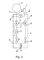
- the pneumatic system 4 is described in detail in FIG FIG. 3 shown. It is fed by a feed device 5, in particular a pressure line.
- the required compressed air can z. B. from the pressure relief valve of a vehicle brake system (not shown) are removed.
- the incoming at the input 4a of the pneumatic system 4 air is passed through a pressure regulator DR to regulate a system pressure, which can be detected via a measuring output 4c about a manometer.
- a first flow path is opened which leads via the valve 44, the multi-way valve 43 and the unlockable valve 45 via the outlet 4b.2 into the filling and evacuation line 3 and thus into the inflatable body 2.
- an overflow 4d serves as a safety valve.
- the air flows during filling via a nozzle 42 to the output 4b.1, to which the pressure sensor 7 is connected, so that it can measure the pressure during filling of the inflatable body 2.
- valve 46 opens, and thus a second flow path, which leads through the valve 46, a Venturi nozzle 41 and the multiway valve 43 to the vent outlet 4e. Air is drawn in via the vacuum connection of the Venturi nozzle 41, which air flows from the inflatable body 2 via the filling and evacuation line 3 into the valve 45 unlocked by the control and from there into the Venturi nozzle 41 and further into the venting outlet 4e.
- the controller works as follows:
- step S1 After execution of the control program, an initialization of the system takes place in step S1. It is then decided in step S2 whether the system is ready for use.
- step S20 If not, the control program is ended, step S20.
- step S2 With a positive system check in step S2, a pressure measurement takes place in step S3, with which the pressure from the sensor 7 (see FIG. Fig. 3 ) is read out. In step S4, it is checked whether the value returned by the pressure sensor 7 is plausible or the data transmitted have unexpected components. If a non-plausible value is detected in step S4, there is an error, then the filling and emptying process is ended in step S11.
- step S5 the controller waits for a predetermined time (timeout time), if something happens, ie whether a correct pressure value (p) has been transmitted to the controller. If YES, the filling and emptying operation is ended, step S6. If NO, a check is made as to whether the detected pressure p has reached or exceeded a predetermined maximum pressure pmax, which is matched to the inflatable body, step S7. If it is determined in S7 that the maximum value pmax has been reached or exceeded, the filling process is stopped in step S8. If the p has not yet reached the value pmax, it is next checked in step S9 whether the pressure p measured by the pressure sensor has reached or fallen below a predetermined minimum value which represents the complete evacuation of the inflatable body.
- step S12 If pmin has not been reached, control proceeds to step S12. If pmin has been reached or undercut, the purge operation is stopped in step S10, and control proceeds to step S12.
- step S12 it is checked whether the vehicle is stationary, for. B. whether the brake is actuated or alternatively or additionally, the wheels of the vehicle to move.
- the latter can z. B. be detected via a corresponding motion sensor.
- a filling process of the inflatable body should only be possible with a non-moving vehicle. If the brake is not applied or the wheels are not stationary, control proceeds to step S14; when the brake is applied or the wheels are stopped, first the discharge operation of the inflatable body is started, then the control proceeds to step S14.
- step S14 it is checked whether the switch for filling or emptying has been pressed. If not, the control proceeds to step S18 and waits a predetermined time (timeout time). As long as the predetermined waiting time is not reached, the control returns to step S2. If the timeout period is reached, either the current filling process or the current emptying process is stopped and the system status is set to FULL or EMPTY / FILLABLE. This status can be visualized in the display in the driver's cab by means of a red or green LED display.
- step S2 the control proceeds to step S2.
- step S14 If the operation of the switch is detected positively in step S14, ie if the switch is pressed, the status of the system is read FULL or EMPTY / FILLABLE. If it is found in step S15 that the status is FULL, the purge operation is started in step S17, and control proceeds to step S18. If it is decided in step S15 that the status is EMPTY / FILLABLE, the filling process is started in step S16 and the control proceeds to step S18.
Landscapes
- Engineering & Computer Science (AREA)
- Mechanical Engineering (AREA)
- Air Bags (AREA)
Abstract
Description
- Die Erfindung betrifft ein Fahrzeug mit Dachsicherheitssystem nach dem Oberbegriff des Anspruchs 1.
- Entsprechende Systeme sind z. B. aus
EP 1 523 421 B1 bekannt. Bei Fahrzeugen wie LKWs wird der Fahrzeugaufbau oftmals mit Planen abgedeckt. Diese haben aufgrund ihrer Flexibilität die Angewohnheit, bei Last auf dem Dachbereich durchzuhängen. Insbesondere sammelt sich bei längeren Standzeiten dort Regenwasser, was im Winter zu Eis gefriert. Vom Dach herunter fallende Eisplatten sind gefährlich, insbesondere für nachfolgende Fahrzeuge, so dass inEP 1 523 421 B1 vorgeschlagen wird, unter dem Planendach einen Schlauch oder Blähkörper in Fahrzeuglängsrichtung zu installieren, der mit Luft befüllbar ist. Wird der Schlauch über ein pneumatisches System mit Luft befüllt, so hebt sich die Plane des Daches im Bereich des Schlauches an und auf dem Dach vorhandenes Material wie Eis oder Wasser kann herunter rutschen. - Aufgabe der vorliegenden Erfindung ist es, ein Fahrzeug der eingangs genannten Art zu schaffen, bei welchem das Dachsicherheitssystem für den Benutzer noch einfacher bedienbar ist und welches noch zuverlässiger arbeitet, wobei insbesondere die Gefahr von Fehlbedienungen und Beschädigungen verringert wird.
- Gelöst wird diese Aufgabe durch ein Fahrzeug mit Dachsicherheitssystem mit den Merkmalen des Anspruchs 1. Vorteilhafte Ausführungsformen finden sich in den Unteransprüchen.
- Erfindungsgemäß ist das pneumatische System mit einem Drucksensor ausgestattet. Der Drucksensor ist in der Lage, mit der Steuerung zu kommunizieren. Die Steuerung koordiniert den Befüllungs- bzw. Entleerungsvorgang des Blähkörpers. Dadurch wird es möglich, den Füllstand des Blähkörpers jederzeit zu erfassen, etwa auch dann, wenn Leckagen auftreten oder dergleichen, etwa dann, wenn der Drucksensor einen Fehler anzeigt oder der gemessene Druck einem bestimmten Sollwert nicht entspricht.
- Damit das Dachsicherheitssystem insbesondere leicht zu bedienen ist, ist ein Schalter zur manuellen Aktivierung des pneumatischen Systems vorgesehen, der mit dem pneumatischen System gekoppelt ist. Der Schalter ist vorteilhafterweise so ausgebildet, dass er das pneumatische System nur bei Stillstand des Fahrzeugs aktivieren kann. Dazu kann der Schalter so ausgelegt sein, dass beim Druck auf diesen geprüft wird, ob die Bremse betätigt ist und/oder die Räder des Fahrzeugs still stehen. Bei einem so ausgebildeten Schalter kann dieser auch entfernt von der Steuerung, insbesondere in der Fahrerkabine des Fahrzeugs vorgesehen sein.
- Weiter ist bevorzugt eine Anzeige vorgesehen, die anzeigt, ob der vom Drucksensor gemessene Istwert dem vorgegebenen Druckwert, d. h. in der Regel dem maximalen Druck, der im Blähkörper herrschen soll, entspricht oder nicht. Insbesondere ist dabei eine LED-Anzeige vorgesehen, die rot leuchtet, wenn der vorgegebene Druckwert erreicht oder überschritten ist und sonst grün leuchtet.
- In dem pneumatischen System, welches vorteilhafterweise in einem Metallblock untergebracht ist und so sehr kompakt ausgeführt werden kann, ist der Drucksensor bevorzugt parallel zur Füll- und Evakuierungsleitung des Blähkörpers geschaltet.
- Die Steuerung ist vorteilhafterweise mit dem pneumatischen System gekoppelt, wobei das pneumatische System einen ersten Strömungsweg mit einem ersten Ventil zum Befüllen des Blähkörpers und einen zweiten Strömungsweg zum Evakuieren des Blähkörpers mit einem zweiten und einem dritten Ventil (46) aufweist. Dabei kann vorgesehen sein, dass der erste Strömungsweg von der Druckeingangsseite des pneumatischen Systems über das erste Ventil durch eine Venturi-Düse und über das zweite Ventil zur an einem ersten Druckausgang angeschlossenen Füll- und Evakuierungsleitung führt. Der vorgesehene Schalter ist dann zur Betätigung des ersten Ventils und/oder zweiten Ventils ausgelegt.
- Bevorzugt führt der zweite Strömungsweg von der Druckeingangsseite des pneumatischen Systems über das dritte Ventil durch die Venturi-Düse zu einem Entlüftungsanschluss des pneumatischen Systems, wobei der Unterdruckanschluss der Venturi-Düse mit der am ersten Druckausgang angeschlossenen Füll- und Evakuierungsleitung verbunden ist. Der Entlüftungsanschluss dient zur Schnellentlüftung des Systems und schafft für den Luftstrom eine kurze Verbindung nach außen, so dass zur Schnellentlüftung der Luftstrom nicht durch das gesamte pneumatische System hindurch geleitet werden muss. Das erste Ventil ist bevorzugt ein Mehrwege-Ventil. Das zweite Ventil ist bevorzugt als ein entriegelbares Ventil ausgebildet, um ggf. auch die umgekehrte Strömungsrichtung zu ermöglichen. Auch das dritte Ventil kann bevorzugt als ein Mehrwege-Ventil ausgebildet sein.
- Die erfindungsgemäße Steuerung arbeitet so, dass regelmäßig der im Drucksensor gemessene Druck abgefragt wird.
- Falls der Drucksensor keinen Fehler detektiert, wird ein eventuell laufender Befüllungs- bzw. Evakuierungsprozess nach Verstreichen einer vorgegebenen Maximalzeitdauer abgebrochen. Sonst wird der am Drucksensor gemessene Druck mit dem voreingestellten Maximaldruck verglichen. Ist der Maximaldruck erreicht oder überschritten, wird der Befüllvorgang abgebrochen. Liegt der Druck unter dem voreingestellten Maximaldruck, wird ein laufender Entleerungsvorgang abgebrochen.
- Falls ein Fehler bei der Druckmessung detektiert wird, wird der Befüllungs- oder Entleerungsvorgang sofort abgebrochen. Bei betätigter Fahrzeugbremse wird dann der Blähkörper aus Sicherheitsgründen zunächst evakuiert.
- Anschließend wird von der Steuerung abgefragt, ob der Schalter betätigt worden ist. Falls dies der Fall ist, wird geprüft, ob der Blähkörper befüllbar ist. Wenn er befüllbar ist, wird der Befüllvorgang gestartet. Wenn er bereits gefüllt ist, wird der Blähkörper entleert.
- Anschließend wartet das System eine vorgegebene Zeitdauer. Solange diese nicht verstrichen ist, wird der Druck weiter gemessen und die oben genannten Abfragen werden durchlaufen. Ist die vorgegebene Zeitdauer verstrichen, wird der Befüll- oder Entleerungsvorgang abgebrochen und der Steuerung der Füllzustand des Blähkörpers als Statusmitteilung übergeben.
- Die Erfindung wird nun anhand der
Figuren 1 bis 4 schematisch näher erläutert: - Figur 1 -
- zeigt eine Teilansicht des Dachaufbaus eines erfindungsgemäßen Fahrzeugs.
- Figur 2 -
- zeigt ein Blockschaltbild der Fahrzeugsteuerung mit angeschlossener Elektrik und dem pneumatischen System.
- Figur 3 -
- zeigt ein Schaltbild des pneumatischen Systems.
- Figur 4 -
- ist ein Flussdiagramm zur Erläuterung der erfindungsgemäßen Steuerung.
- Der in
Figur 1 gezeigte Teil des Dachs des erfindungsgemäßen Fahrzeugs 100 weist quer zur Fahrtrichtung verlaufende Querspriegel 12 auf, auf denen ein sich im Wesentlichen in Fahrzeuglängsrichtung erstreckender schlauchförmiger Blähkörper 2 befindet, der in der Regel mit den Querspriegeln über Gurte oder Schnallen verbunden ist. Der Blähkörper ist zwischen Querspriegel 12 und Dachplane 1 angeordnet. Wird der Blähkörper mit Luft befüllt, so dehnt er sich aus und hebt das Dach 1 an, wie inFigur 1 gezeigt. So kann Wasser oder auch Eis auf dem Dach herunter rutschen. - In dem in
Figur 2 gezeigten Blockschaltbild ist die Steuerung des Systems mit 6 bezeichnet. Diese ist einerseits zur Spannungsversorgung mit der Fahrzeugelektrik, dem Fahrzeugnetz 14, einer Batterie 13 oder/und einem Solarregler 10 gekoppelt, deren Ausgänge über einen Spannungsregler 61 der Steuerung zugeführt sind. Die Steuerung selbst umfasst eine Zentralrechnereinheit 60, die die Ein- und Ausgänge der Steuerung 6 ausliest bzw. anspricht. - Die Steuerung kann z. B. über ein Relais 63 mit einem GPS-System gekoppelt sein, um die Position des Fahrzeugs bestimmen zu können und zur Wartung weiterzuleiten. Weiter kann ein 24V-Spannungsausgang 62 vorgesehen sein.
- Über einen Optokoppler 64 kann der Zustand der Fahrzeugbremse ausgelesen werden, damit sicher gestellt ist, dass das pneumatische System nicht während der Fahrt aktiviert wird. Weiter können LEDs (rot/grün) über einen I/O-Port 65 angesprochen werden, der ebenfalls die Betätigung des Schalters 8 durch den Fahrer an die Zentralrechnereinheit 60 meldet. LEDs und der Schalter 8 können an der Steuerung angeordnet sein oder auch entfernt von dieser, insbesondere können sie in der Fahrerkabine des Fahrzeugs vorgesehen werden.
- Weiter ist die Steuerung mit dem pneumatischen System 4 gekoppelt. Über Optokoppler 67, 68 können Ventile 46, 44 45, angesprochen werden. Über ein Bussystem steht der Drucksensor 7 des pneumatischen Systems 4 mit der Steuerung 6 und der Zentralrechnereinheit 60 in Verbindung. Über eine Füll- und Evakuierungsleitung 3 ist das pneumatische System mit dem Blähkörper 2 verbunden.
- Das pneumatische System 4 ist im Detail in
Figur 3 dargestellt. Es wird gespeist durch eine Zuführeinrichtung 5, insbesondere eine Druckleitung. Die erforderliche Druckluft kann z. B. aus dem Überdruckventil eines Fahrzeugbremssystems (nicht gezeigt) entnommen werden. Die am Eingang 4a des pneumatischen Systems 4 ankommende Luft wird über einen Druckregler DR geführt, um einen Systemdruck einzuregeln, der über einen Messausgang 4c etwa über ein Manometer erfasst werden kann. - Wird der Schalter zum Befüllen betätigt, wird ein erster Strömungsweg geöffnet, der über das Ventil 44, das Mehrwege-Ventil 43 und das entriegelbare Ventil 45 über den Ausgang 4b.2 in die Füll- und Evakuierungsleitung 3 und so in den Blähkörper 2 führt. Wird der Druck zu hoch, dient ein Überströmausgang 4d als Sicherheitsventil. Neben dem Ausgang 4b.2 strömt die Luft beim Befüllen auch über eine Düse 42 zum Ausgang 4b.1, an welchem der Drucksensor 7 angeschlossen ist, so dass dieser beim Befüllen des Blähkörpers 2 den Druck messen kann.
- Wird der Schalter zum Entleeren betätigt, so öffnet sich durch die Steuerung vermittelt das Ventil 46 und damit ein zweiter Strömungsweg, welcher durch das Ventil 46, eine Venturi-Düse 41 und das Mehrwegeventil 43 zum Entlüftungsauslass 4e führt. Über den Unterdruckanschluss der Venturi-Düse 41 wird Luft angesaugt, welche aus dem Blähkörper 2 über die Füll- und Evakuierungsleitung 3 in das hierzu durch die Steuerung entriegelte Ventil 45 und von dort in die Venturi-Düse 41 und weiter in den Entlüftungsauslass 4e strömt.
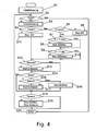
- Wie in
Figur 4 gezeigt, arbeitet die Steuerung wie folgt: - Nach Ausführung des Steuerprogramms erfolgt in Schritt S1 eine Initialisierung des Systems. Anschließend wird in Schritt S2 entschieden, ob das System einsatzbereit ist.
- Wenn nein, wird das Steuerprogramm beendet, Schritt S20.
- Bei positivem Systemcheck in Schritt S2 erfolgt eine Druckmessung in Schritt S3, mit der der Druck aus dem Sensor 7 (vgl.
Fig. 3 ) ausgelesen wird. In Schritt S4 wird geprüft, ob der vom Drucksensor 7 zurückgegebene Wert plausibel ist oder die übermittelten Daten nicht erwartete Bestandteile haben. Wird ein nicht plausibler Wert in Schritt S4 festgestellt, liegt ein Fehler vor, es wird dann der Befüll- bzw. der Entleerungsvorgang in Schritt S11 beendet. - Liegt kein Fehler vor, so fährt die Steuerung mit Schritt S5 fort, in dem die Steuerung für eine vorgegebene Zeit (Timeout-Zeit) wartet, ob etwas geschieht, d. h. ob ein korrekter Druckwert (p) an die Steuerung übermittelt wurde. Falls JA wird der Befüll- bzw. Entleerungsvorgang beendet, Schritt S6. Falls NEIN erfolgt eine Prüfung, ob der erfasste Druck p einen vorgegebenen, auf den Blähkörper abgestimmten Maximaldruck pmax erreicht oder überschritten hat, Schritt S7. Falls in S7 festgestellt wird, dass der Maximalwert pmax erreicht oder überschritten wurde, wird in Schritt S8 der Befüllvorgang gestoppt. Wenn der p den Wert pmax noch nicht erreicht hat, wird als nächstes in Schritt S9 geprüft, ob der vom Drucksensor gemessene Druck p einen vorgegebenen Minimalwert, der für die vollständige Evakuierung des Blähkörpers steht, erreicht oder unterschritten hat.
- Wenn pmin nicht erreicht wurde, fährt die Steuerung mit Schritt S12 fort. Wenn pmin erreicht oder unterschritten wurde, wird in Schritt S10 der Entleerungsvorgang gestoppt und die Steuerung fährt mit Schritt S12 fort.
- In Schritt S12 wird geprüft, ob das Fahrzeug still steht, z. B. ob die Bremse betätigt ist oder alternativ oder ergänzend die Räder des Fahrzeugs sich bewegen. Letzeres kann z. B. über einen entsprechenden Bewegungssensor erfasst werden. Sicherheitshalber soll ein Befüllvorgang des Blähkörpers nur bei einem nicht fahrenden Fahrzeug möglich sein. Wenn die Bremse nicht betätigt ist oder die Räder nicht still stehen, fährt die Steuerung mit Schritt S14 fort; wenn die Bremse betätigt ist oder die Räder stillstehen, wird zunächst der Entleerungsvorgang des Blähkörpers gestartet, dann fährt die Steuerung mit Schritt S14 fort.
- In Schritt S14 wird geprüft, ob der Schalter zum Füllen oder Entleeren gedrückt worden ist. Wenn nein, fährt die Steuerung mit Schritt S18 fort und wartet eine vorgegebene Zeit (Timeoutzeit). Solange die vorgegebene Wartezeit nicht erreicht ist, springt die Steuerung zu Schritt S2 zurück. Ist die Timeoutzeit erreicht, wird entweder der laufende Befüllvorgang oder der laufende Entleerungsvorgang gestoppt und der Systemstatus entsprechend auf VOLL oder LEER/BEFÜLLBAR gestellt. Dieser Status kann in der Anzeige in der Fahrerkabine durch eine rote bzw. grüne LED-Anzeige sichtbar gemacht werden.
- Anschließend fährt die Steuerung mit Schritt S2 fort.
- Wird in Schritt S14 die Betätigung des Schalters positiv festgestellt, ist also der Schalter gedrückt, wird der Status des Systems VOLL oder LEER/BEFÜLLBAR ausgelesen. Falls in Schritt S15 gefunden wird, dass der Status VOLL ist, wird in Schritt S17 der Entleerungsvorgang gestartet und die Steuerung fährt mit Schritt S18 fort. Wird in Schritt S15 entschieden, dass der Status LEER/BEFÜLLBAR ist, wird in Schritt S16 der Befüllvorgang gestartet und die Steuerung fährt mit Schritt S18 fort.
- Auf diese Weise kann eine zuverlässige Steuerung der Befüllung oder Entleerung des Blähkörpers sicher gestellt werden, wobei der Fahrer jederzeit über den Zustand des Systems informiert ist.
Claims (14)
- Fahrzeug mit Dachsicherheitssystem und Abdeckplane (1) und einem die Abdeckplane (1) tragenden Fahrzeugaufbau (12), wobei das Dachsicherheitssystem einen mit Fluid befüllbaren Blähkörper (2), insbesondere einen Schlauch aufweist, der zwischen Fahrzeugaufbau (12) und Abdeckplane (1) angeordnet und dazu ausgelegt ist, beim Befüllen zur Vermeidung oder Beseitigung von Ansammlungen, insbesondere Wasser, auf der Dachfläche die Abdeckplane (1) anzuheben, wobei der Blähkörper (2) an eine Füll- und Evakuierungsleitung (3) angeschlossen ist, die über ein pneumatisches System (4) mit einer an dessen Druckeingangsseite (4a) angeordneten Zuführeinrichtung (5) verbunden ist, durch welche ein vorgegebener Luftdruck an der Druckeingangsseite (4a) des pneumatischen Systems (4) anliegt, wobei weiter eine Steuerung (6) vorgesehen ist, welche dazu ausgelegt ist, die Befüllung bzw. Evakuierung des Blähkörpers (2) zu steuern, wobei die Steuerung weiter so ausgelegt ist, dass die Befüllung des Blähkörpers (2) bei Erreichen eines vorgegebenen Druckwertes gestoppt wird,
dadurch gekennzeichnet,
dass an der Druckausgangsseite (4b.1) des pneumatischen Systems (4) ein mit der Steuerung (6) kommunizierender Drucksensor (7) vorgesehen ist, der den im Blähkörper (2) herrschenden Druck zur Übermittlung an die Steuerung (6) erfasst. - Fahrzeug nach Anspruch 1,
dadurch gekennzeichnet,
dass ein Schalter (8) zur manuellen Aktivierung des pneumatischen Systems (4) vorgesehen ist. - Fahrzeug nach Anspruch 2,
dadurch gekennzeichnet,
dass der Schalter (8) so ausgelegt ist, dass er nur bei Stillstand des Fahrzeugs das pneumatische System aktivieren kann. - Fahrzeug nach einem der vorigen Ansprüche,
dadurch gekennzeichnet,
dass der Drucksensor (7) parallel zur Füll- und Evakuierungsleitung (3) des Blähkörpers (2) geschaltet ist. - Fahrzeug nach einem der vorigen Ansprüche,
dadurch gekennzeichnet,
dass eine Anzeige (9) vorgesehen ist, die anzeigt, ob der vom Drucksensor (7) gemessene Istwert dem vorgegebenen Druckwert entspricht oder nicht. - Fahrzeug nach Anspruch 5,
dadurch gekennzeichnet,
dass eine LED-Anzeige (9) vorgesehen ist, die Rot leuchtet, wenn der vorgegebene Druckwert erreicht oder überschritten ist und sonst Grün leuchtet. - Fahrzeug nach einem der vorigen Ansprüche,
dadurch gekennzeichnet,
dass die Steuerung (6) mit dem pneumatischen System (4) gekoppelt ist, wobei das pneumatische System einen ersten Strömungsweg mit einem ersten Ventil (44) zum Befüllen des Blähkörpers (2) und einem zweiten Strömungsweg zum Evakuieren des Blähkörpers (2) mit einem zweiten (45) und einem dritten Ventil (46) aufweist. - Fahrzeug nach Anspruch 7,
dadurch gekennzeichnet,
dass der erste Strömungsweg von der Druckeingangsseite (4a) des pneumatischen Systems (4) über das erste Ventil (44) durch eine Venturi-Düse (41) und über das zweite Ventil (45) zur an einem ersten Druckausgang (4b.2) angeschlossenen Füll- und Evakuierungsleitung (3) führt. - Fahrzeug nach Anspruch 7 oder 8,
dadurch gekennzeichnet,
dass der Schalter (9) zur Betätigung des ersten Ventils (44) und/oder ersten Ventils (45) ausgelegt ist. - Fahrzeug nach Anspruch 9 oder 10,
dadurch gekennzeichnet,
dass der zweite Strömungsweg von der Druckeingangsseite (4a) des pneumatischen Systems (4) über das dritte Ventil (46) durch die Venturi-Düse (41) zu einem Entlüftungsanschluss (4e) des pneumatischen Systems (4) führt, wobei der Unterdruckanschluss der Venturi-Düse (41) mit der am ersten Druckausgang (4b.2) angeschlossenen Füll- und Evakuierungsleitung (3) verbunden ist. - Fahrzeug nach einem der Ansprüche 5 bis 10,
dadurch gekennzeichnet,
dass das erste Ventil (44) ein Mehrwege-Ventil ist. - Fahrzeug nach einem der Ansprüche 7 bis 11,
dadurch gekennzeichnet,
dass das zweite Ventil (45) ein entriegelbares Ventil ist. - Fahrzeug nach einem der Ansprüche 7 bis 12,
dadurch gekennzeichnet,
dass das dritte Ventil (46) ein Mehrwege-Ventil ist. - Fahrzeug nach einem der vorigen Ansprüche,
dadurch gekennzeichnet,
dass das pneumatische System (4) in einem Metallblock untergebracht ist.
Applications Claiming Priority (1)
| Application Number | Priority Date | Filing Date | Title |
|---|---|---|---|
| DE202012000196U DE202012000196U1 (de) | 2012-01-10 | 2012-01-10 | Fahrzeug mit Dachsicherheitssystem |
Publications (3)
| Publication Number | Publication Date |
|---|---|
| EP2614975A2 true EP2614975A2 (de) | 2013-07-17 |
| EP2614975A3 EP2614975A3 (de) | 2015-12-09 |
| EP2614975B1 EP2614975B1 (de) | 2020-06-10 |
Family
ID=45923691
Family Applications (1)
| Application Number | Title | Priority Date | Filing Date |
|---|---|---|---|
| EP13000085.4A Active EP2614975B1 (de) | 2012-01-10 | 2013-01-09 | Fahrzeug mit Dachsicherheitssystem |
Country Status (2)
| Country | Link |
|---|---|
| EP (1) | EP2614975B1 (de) |
| DE (1) | DE202012000196U1 (de) |
Cited By (2)
| Publication number | Priority date | Publication date | Assignee | Title |
|---|---|---|---|---|
| DE202017107954U1 (de) | 2017-12-29 | 2018-01-16 | Johannes Köhler | Fahrzeug mit Dachsicherheitssystem |
| CN111546973A (zh) * | 2020-04-07 | 2020-08-18 | 濮阳市飞翔房车实业有限公司 | 一种可扩展式房车车厢 |
Families Citing this family (1)
| Publication number | Priority date | Publication date | Assignee | Title |
|---|---|---|---|---|
| DE102022127264A1 (de) * | 2022-10-18 | 2024-04-18 | ADVENATE GmbH | Entlüftungsgerät |
Citations (1)
| Publication number | Priority date | Publication date | Assignee | Title |
|---|---|---|---|---|
| EP1523421B1 (de) | 2002-05-31 | 2006-02-01 | K & M Stahl-, Behälter-, fassaden und Metallbau Gmbh | Vorrichtung zur erhöhung der verkehrssicherheit beplanter fahrzeuge |
Family Cites Families (3)
| Publication number | Priority date | Publication date | Assignee | Title |
|---|---|---|---|---|
| DE202004000295U1 (de) * | 2004-01-09 | 2004-04-08 | Bauregger, Günter | Spann-Hebeeinrichtung für ein Fahrzeugplanenoberteil |
| DE102008012701B4 (de) * | 2008-03-05 | 2012-02-09 | Knorr-Bremse Systeme für Nutzfahrzeuge GmbH | Enteisungsvorrichtung für eine Nutzfahrzeugplane |
| NL1036444C2 (nl) * | 2009-01-21 | 2010-07-22 | Robert Ferdinand Victor De Ruiter | Inrichting voor het liften van een zeildak van een trailer. |
-
2012
- 2012-01-10 DE DE202012000196U patent/DE202012000196U1/de not_active Expired - Lifetime
-
2013
- 2013-01-09 EP EP13000085.4A patent/EP2614975B1/de active Active
Patent Citations (1)
| Publication number | Priority date | Publication date | Assignee | Title |
|---|---|---|---|---|
| EP1523421B1 (de) | 2002-05-31 | 2006-02-01 | K & M Stahl-, Behälter-, fassaden und Metallbau Gmbh | Vorrichtung zur erhöhung der verkehrssicherheit beplanter fahrzeuge |
Cited By (2)
| Publication number | Priority date | Publication date | Assignee | Title |
|---|---|---|---|---|
| DE202017107954U1 (de) | 2017-12-29 | 2018-01-16 | Johannes Köhler | Fahrzeug mit Dachsicherheitssystem |
| CN111546973A (zh) * | 2020-04-07 | 2020-08-18 | 濮阳市飞翔房车实业有限公司 | 一种可扩展式房车车厢 |
Also Published As
| Publication number | Publication date |
|---|---|
| DE202012000196U1 (de) | 2012-03-01 |
| EP2614975B1 (de) | 2020-06-10 |
| EP2614975A3 (de) | 2015-12-09 |
Similar Documents
| Publication | Publication Date | Title |
|---|---|---|
| DE102015116317B4 (de) | Elektro-pneumatische Parkbremseinrichtung eines Fahrzeugs mit weiterem Steuerkreis und Zugfahrzeug mit elektro-pneumatischer Parkbremseinrichtung | |
| EP3013624B1 (de) | Druckluftsystem | |
| EP3341253B1 (de) | Elektrische parkbremseinrichtung mit zusätzlicher energieversorgung | |
| EP2836406B1 (de) | Luftaufbereitungsanlage für die druckluftversorgung von nutzkraftfahrzeugen | |
| EP2298616B1 (de) | Steuergerät und Verfahren zum Testen einer Ventileinrichtung einer elektrischen Feststellbremse | |
| EP2121395A2 (de) | Anhängefahrzeugbrems- und luftfederungsanlage | |
| DE19514603C2 (de) | Druckluft-Bremsanlage für ein Nutzfahrzeug | |
| DE102016112888A1 (de) | Flüssiggasanlage | |
| EP2686215B1 (de) | Lufttrockneradaptermodul, lufttrocknermodul und druckluftversorgungseinrichtung | |
| EP2614975B1 (de) | Fahrzeug mit Dachsicherheitssystem | |
| EP1651491B1 (de) | Vorrichtung zum wiederbefüllen von bremskreisen nach einem starken druckluftverbrauch und vorrichtung zur durchführung des verfahrens | |
| DE102009005229C5 (de) | Luftfederanlage mit Höhenbegrenzung | |
| EP3247603A1 (de) | Vorrichtung und verfahren zum versorgen eines nutzfahrzeugs mit druckluft | |
| DE102012020818A1 (de) | Bremsvorrichtung für Arbeitsmaschinen und Verfahren zum Betätigen der Bremsvorrichtung | |
| DE102007052286B4 (de) | Ventilanordnung zur Steuerung einer Bremsanlage einer Feststellbremsanlage eines Schienenfahrzeugs | |
| EP1884428A2 (de) | Druckluftaufbereitungseinrichtung zum Versorgen einer Kraftfahrzeugbremsanlage mit Druckluft | |
| DE102010015502A1 (de) | Vorrichtung und Verfahren zum Sensieren und Plausibilitätsüberwachen zumindest eines Drucks | |
| DE3800541C2 (de) | ||
| EP2576425A1 (de) | Pumpanordnung und versorgungseinheit für kraftstoff mit pumpanordnung | |
| WO2016030057A1 (de) | Schlupfgeregelte hydraulische zweikreis-fahrzeugbremsanlage und betriebsverfahren dafür | |
| DE10209913C1 (de) | Notbremsüberbrückungseinrichtung zur Ansteuerung von elektropneumatischen Zugbremseinrichtungen in Triebfahrzeugen und Steuerwagen mit konventioneller Bremstechnik | |
| DE202017107954U1 (de) | Fahrzeug mit Dachsicherheitssystem | |
| DE102007052291B4 (de) | Ventilanordnung zur Steuerung einer Feststellbremsanlage eines Schienenfahrzeugs | |
| DE2056636C3 (de) | Luftfederung für Tandemachsen von Fahrzeugen mit Niveauregelung und Regelung der Achslastverteilung | |
| DE202010001124U1 (de) | Vorrichtung zum Heben einer Dachplane eines Trailers |
Legal Events
| Date | Code | Title | Description |
|---|---|---|---|
| PUAI | Public reference made under article 153(3) epc to a published international application that has entered the european phase |
Free format text: ORIGINAL CODE: 0009012 |
|
| AK | Designated contracting states |
Kind code of ref document: A2 Designated state(s): AL AT BE BG CH CY CZ DE DK EE ES FI FR GB GR HR HU IE IS IT LI LT LU LV MC MK MT NL NO PL PT RO RS SE SI SK SM TR |
|
| AX | Request for extension of the european patent |
Extension state: BA ME |
|
| PUAL | Search report despatched |
Free format text: ORIGINAL CODE: 0009013 |
|
| AK | Designated contracting states |
Kind code of ref document: A3 Designated state(s): AL AT BE BG CH CY CZ DE DK EE ES FI FR GB GR HR HU IE IS IT LI LT LU LV MC MK MT NL NO PL PT RO RS SE SI SK SM TR |
|
| AX | Request for extension of the european patent |
Extension state: BA ME |
|
| RIC1 | Information provided on ipc code assigned before grant |
Ipc: B60J 7/00 20060101AFI20151102BHEP |
|
| 17P | Request for examination filed |
Effective date: 20160518 |
|
| RBV | Designated contracting states (corrected) |
Designated state(s): AL AT BE BG CH CY CZ DE DK EE ES FI FR GB GR HR HU IE IS IT LI LT LU LV MC MK MT NL NO PL PT RO RS SE SI SK SM TR |
|
| STAA | Information on the status of an ep patent application or granted ep patent |
Free format text: STATUS: EXAMINATION IS IN PROGRESS |
|
| 17Q | First examination report despatched |
Effective date: 20170123 |
|
| GRAP | Despatch of communication of intention to grant a patent |
Free format text: ORIGINAL CODE: EPIDOSNIGR1 |
|
| STAA | Information on the status of an ep patent application or granted ep patent |
Free format text: STATUS: GRANT OF PATENT IS INTENDED |
|
| INTG | Intention to grant announced |
Effective date: 20200219 |
|
| GRAS | Grant fee paid |
Free format text: ORIGINAL CODE: EPIDOSNIGR3 |
|
| GRAA | (expected) grant |
Free format text: ORIGINAL CODE: 0009210 |
|
| STAA | Information on the status of an ep patent application or granted ep patent |
Free format text: STATUS: THE PATENT HAS BEEN GRANTED |
|
| AK | Designated contracting states |
Kind code of ref document: B1 Designated state(s): AL AT BE BG CH CY CZ DE DK EE ES FI FR GB GR HR HU IE IS IT LI LT LU LV MC MK MT NL NO PL PT RO RS SE SI SK SM TR |
|
| REG | Reference to a national code |
Ref country code: GB Ref legal event code: FG4D Free format text: NOT ENGLISH |
|
| REG | Reference to a national code |
Ref country code: AT Ref legal event code: REF Ref document number: 1278906 Country of ref document: AT Kind code of ref document: T Effective date: 20200615 Ref country code: CH Ref legal event code: EP |
|
| REG | Reference to a national code |
Ref country code: DE Ref legal event code: R096 Ref document number: 502013014775 Country of ref document: DE |
|
| REG | Reference to a national code |
Ref country code: IE Ref legal event code: FG4D Free format text: LANGUAGE OF EP DOCUMENT: GERMAN |
|
| REG | Reference to a national code |
Ref country code: CH Ref legal event code: NV Representative=s name: SCHMAUDER AND PARTNER AG PATENT- UND MARKENANW, CH |
|
| REG | Reference to a national code |
Ref country code: SE Ref legal event code: TRGR |
|
| REG | Reference to a national code |
Ref country code: NL Ref legal event code: FP |
|
| REG | Reference to a national code |
Ref country code: LT Ref legal event code: MG4D |
|
| PG25 | Lapsed in a contracting state [announced via postgrant information from national office to epo] |
Ref country code: LT Free format text: LAPSE BECAUSE OF FAILURE TO SUBMIT A TRANSLATION OF THE DESCRIPTION OR TO PAY THE FEE WITHIN THE PRESCRIBED TIME-LIMIT Effective date: 20200610 Ref country code: FI Free format text: LAPSE BECAUSE OF FAILURE TO SUBMIT A TRANSLATION OF THE DESCRIPTION OR TO PAY THE FEE WITHIN THE PRESCRIBED TIME-LIMIT Effective date: 20200610 Ref country code: GR Free format text: LAPSE BECAUSE OF FAILURE TO SUBMIT A TRANSLATION OF THE DESCRIPTION OR TO PAY THE FEE WITHIN THE PRESCRIBED TIME-LIMIT Effective date: 20200911 Ref country code: NO Free format text: LAPSE BECAUSE OF FAILURE TO SUBMIT A TRANSLATION OF THE DESCRIPTION OR TO PAY THE FEE WITHIN THE PRESCRIBED TIME-LIMIT Effective date: 20200910 |
|
| PG25 | Lapsed in a contracting state [announced via postgrant information from national office to epo] |
Ref country code: HR Free format text: LAPSE BECAUSE OF FAILURE TO SUBMIT A TRANSLATION OF THE DESCRIPTION OR TO PAY THE FEE WITHIN THE PRESCRIBED TIME-LIMIT Effective date: 20200610 Ref country code: LV Free format text: LAPSE BECAUSE OF FAILURE TO SUBMIT A TRANSLATION OF THE DESCRIPTION OR TO PAY THE FEE WITHIN THE PRESCRIBED TIME-LIMIT Effective date: 20200610 Ref country code: RS Free format text: LAPSE BECAUSE OF FAILURE TO SUBMIT A TRANSLATION OF THE DESCRIPTION OR TO PAY THE FEE WITHIN THE PRESCRIBED TIME-LIMIT Effective date: 20200610 Ref country code: BG Free format text: LAPSE BECAUSE OF FAILURE TO SUBMIT A TRANSLATION OF THE DESCRIPTION OR TO PAY THE FEE WITHIN THE PRESCRIBED TIME-LIMIT Effective date: 20200910 |
|
| PG25 | Lapsed in a contracting state [announced via postgrant information from national office to epo] |
Ref country code: AL Free format text: LAPSE BECAUSE OF FAILURE TO SUBMIT A TRANSLATION OF THE DESCRIPTION OR TO PAY THE FEE WITHIN THE PRESCRIBED TIME-LIMIT Effective date: 20200610 |
|
| PG25 | Lapsed in a contracting state [announced via postgrant information from national office to epo] |
Ref country code: ES Free format text: LAPSE BECAUSE OF FAILURE TO SUBMIT A TRANSLATION OF THE DESCRIPTION OR TO PAY THE FEE WITHIN THE PRESCRIBED TIME-LIMIT Effective date: 20200610 Ref country code: PT Free format text: LAPSE BECAUSE OF FAILURE TO SUBMIT A TRANSLATION OF THE DESCRIPTION OR TO PAY THE FEE WITHIN THE PRESCRIBED TIME-LIMIT Effective date: 20201012 Ref country code: CZ Free format text: LAPSE BECAUSE OF FAILURE TO SUBMIT A TRANSLATION OF THE DESCRIPTION OR TO PAY THE FEE WITHIN THE PRESCRIBED TIME-LIMIT Effective date: 20200610 Ref country code: IT Free format text: LAPSE BECAUSE OF FAILURE TO SUBMIT A TRANSLATION OF THE DESCRIPTION OR TO PAY THE FEE WITHIN THE PRESCRIBED TIME-LIMIT Effective date: 20200610 Ref country code: RO Free format text: LAPSE BECAUSE OF FAILURE TO SUBMIT A TRANSLATION OF THE DESCRIPTION OR TO PAY THE FEE WITHIN THE PRESCRIBED TIME-LIMIT Effective date: 20200610 Ref country code: EE Free format text: LAPSE BECAUSE OF FAILURE TO SUBMIT A TRANSLATION OF THE DESCRIPTION OR TO PAY THE FEE WITHIN THE PRESCRIBED TIME-LIMIT Effective date: 20200610 Ref country code: SM Free format text: LAPSE BECAUSE OF FAILURE TO SUBMIT A TRANSLATION OF THE DESCRIPTION OR TO PAY THE FEE WITHIN THE PRESCRIBED TIME-LIMIT Effective date: 20200610 |
|
| PG25 | Lapsed in a contracting state [announced via postgrant information from national office to epo] |
Ref country code: IS Free format text: LAPSE BECAUSE OF FAILURE TO SUBMIT A TRANSLATION OF THE DESCRIPTION OR TO PAY THE FEE WITHIN THE PRESCRIBED TIME-LIMIT Effective date: 20201010 Ref country code: SK Free format text: LAPSE BECAUSE OF FAILURE TO SUBMIT A TRANSLATION OF THE DESCRIPTION OR TO PAY THE FEE WITHIN THE PRESCRIBED TIME-LIMIT Effective date: 20200610 Ref country code: PL Free format text: LAPSE BECAUSE OF FAILURE TO SUBMIT A TRANSLATION OF THE DESCRIPTION OR TO PAY THE FEE WITHIN THE PRESCRIBED TIME-LIMIT Effective date: 20200610 |
|
| REG | Reference to a national code |
Ref country code: DE Ref legal event code: R097 Ref document number: 502013014775 Country of ref document: DE |
|
| PLBE | No opposition filed within time limit |
Free format text: ORIGINAL CODE: 0009261 |
|
| STAA | Information on the status of an ep patent application or granted ep patent |
Free format text: STATUS: NO OPPOSITION FILED WITHIN TIME LIMIT |
|
| PG25 | Lapsed in a contracting state [announced via postgrant information from national office to epo] |
Ref country code: DK Free format text: LAPSE BECAUSE OF FAILURE TO SUBMIT A TRANSLATION OF THE DESCRIPTION OR TO PAY THE FEE WITHIN THE PRESCRIBED TIME-LIMIT Effective date: 20200610 |
|
| 26N | No opposition filed |
Effective date: 20210311 |
|
| PG25 | Lapsed in a contracting state [announced via postgrant information from national office to epo] |
Ref country code: SI Free format text: LAPSE BECAUSE OF FAILURE TO SUBMIT A TRANSLATION OF THE DESCRIPTION OR TO PAY THE FEE WITHIN THE PRESCRIBED TIME-LIMIT Effective date: 20200610 |
|
| PG25 | Lapsed in a contracting state [announced via postgrant information from national office to epo] |
Ref country code: MC Free format text: LAPSE BECAUSE OF FAILURE TO SUBMIT A TRANSLATION OF THE DESCRIPTION OR TO PAY THE FEE WITHIN THE PRESCRIBED TIME-LIMIT Effective date: 20200610 |
|
| PG25 | Lapsed in a contracting state [announced via postgrant information from national office to epo] |
Ref country code: LU Free format text: LAPSE BECAUSE OF NON-PAYMENT OF DUE FEES Effective date: 20210109 |
|
| PG25 | Lapsed in a contracting state [announced via postgrant information from national office to epo] |
Ref country code: IE Free format text: LAPSE BECAUSE OF NON-PAYMENT OF DUE FEES Effective date: 20210109 |
|
| PG25 | Lapsed in a contracting state [announced via postgrant information from national office to epo] |
Ref country code: HU Free format text: LAPSE BECAUSE OF FAILURE TO SUBMIT A TRANSLATION OF THE DESCRIPTION OR TO PAY THE FEE WITHIN THE PRESCRIBED TIME-LIMIT; INVALID AB INITIO Effective date: 20130109 |
|
| PG25 | Lapsed in a contracting state [announced via postgrant information from national office to epo] |
Ref country code: CY Free format text: LAPSE BECAUSE OF FAILURE TO SUBMIT A TRANSLATION OF THE DESCRIPTION OR TO PAY THE FEE WITHIN THE PRESCRIBED TIME-LIMIT Effective date: 20200610 |
|
| PG25 | Lapsed in a contracting state [announced via postgrant information from national office to epo] |
Ref country code: MK Free format text: LAPSE BECAUSE OF FAILURE TO SUBMIT A TRANSLATION OF THE DESCRIPTION OR TO PAY THE FEE WITHIN THE PRESCRIBED TIME-LIMIT Effective date: 20200610 |
|
| PG25 | Lapsed in a contracting state [announced via postgrant information from national office to epo] |
Ref country code: MT Free format text: LAPSE BECAUSE OF FAILURE TO SUBMIT A TRANSLATION OF THE DESCRIPTION OR TO PAY THE FEE WITHIN THE PRESCRIBED TIME-LIMIT Effective date: 20200610 |
|
| PG25 | Lapsed in a contracting state [announced via postgrant information from national office to epo] |
Ref country code: TR Free format text: LAPSE BECAUSE OF FAILURE TO SUBMIT A TRANSLATION OF THE DESCRIPTION OR TO PAY THE FEE WITHIN THE PRESCRIBED TIME-LIMIT Effective date: 20200610 |
|
| REG | Reference to a national code |
Ref country code: CH Ref legal event code: U11 Free format text: ST27 STATUS EVENT CODE: U-0-0-U10-U11 (AS PROVIDED BY THE NATIONAL OFFICE) Effective date: 20260201 |
|
| PGFP | Annual fee paid to national office [announced via postgrant information from national office to epo] |
Ref country code: NL Payment date: 20260121 Year of fee payment: 14 |
|
| PGFP | Annual fee paid to national office [announced via postgrant information from national office to epo] |
Ref country code: SE Payment date: 20260121 Year of fee payment: 14 |
|
| PGFP | Annual fee paid to national office [announced via postgrant information from national office to epo] |
Ref country code: GB Payment date: 20260113 Year of fee payment: 14 |
|
| PGFP | Annual fee paid to national office [announced via postgrant information from national office to epo] |
Ref country code: DE Payment date: 20260225 Year of fee payment: 14 |
|
| PGFP | Annual fee paid to national office [announced via postgrant information from national office to epo] |
Ref country code: AT Payment date: 20260119 Year of fee payment: 14 |
|
| PGFP | Annual fee paid to national office [announced via postgrant information from national office to epo] |
Ref country code: BE Payment date: 20260121 Year of fee payment: 14 |
|
| PGFP | Annual fee paid to national office [announced via postgrant information from national office to epo] |
Ref country code: FR Payment date: 20260121 Year of fee payment: 14 |
|
| PGFP | Annual fee paid to national office [announced via postgrant information from national office to epo] |
Ref country code: CH Payment date: 20260201 Year of fee payment: 14 |