EP2614422B1 - Motion control touch screen method and apparatus - Google Patents
Motion control touch screen method and apparatus Download PDFInfo
- Publication number
- EP2614422B1 EP2614422B1 EP11823778.3A EP11823778A EP2614422B1 EP 2614422 B1 EP2614422 B1 EP 2614422B1 EP 11823778 A EP11823778 A EP 11823778A EP 2614422 B1 EP2614422 B1 EP 2614422B1
- Authority
- EP
- European Patent Office
- Prior art keywords
- touch
- touch screen
- pressure
- axis
- motion
- Prior art date
- Legal status (The legal status is an assumption and is not a legal conclusion. Google has not performed a legal analysis and makes no representation as to the accuracy of the status listed.)
- Not-in-force
Links
Images


Classifications
-
- G—PHYSICS
- G06—COMPUTING OR CALCULATING; COUNTING
- G06F—ELECTRIC DIGITAL DATA PROCESSING
- G06F3/00—Input arrangements for transferring data to be processed into a form capable of being handled by the computer; Output arrangements for transferring data from processing unit to output unit, e.g. interface arrangements
- G06F3/01—Input arrangements or combined input and output arrangements for interaction between user and computer
- G06F3/03—Arrangements for converting the position or the displacement of a member into a coded form
- G06F3/041—Digitisers, e.g. for touch screens or touch pads, characterised by the transducing means
- G06F3/0412—Digitisers structurally integrated in a display
-
- G—PHYSICS
- G06—COMPUTING OR CALCULATING; COUNTING
- G06F—ELECTRIC DIGITAL DATA PROCESSING
- G06F3/00—Input arrangements for transferring data to be processed into a form capable of being handled by the computer; Output arrangements for transferring data from processing unit to output unit, e.g. interface arrangements
- G06F3/01—Input arrangements or combined input and output arrangements for interaction between user and computer
- G06F3/03—Arrangements for converting the position or the displacement of a member into a coded form
- G06F3/041—Digitisers, e.g. for touch screens or touch pads, characterised by the transducing means
- G06F3/0414—Digitisers, e.g. for touch screens or touch pads, characterised by the transducing means using force sensing means to determine a position
-
- G—PHYSICS
- G06—COMPUTING OR CALCULATING; COUNTING
- G06F—ELECTRIC DIGITAL DATA PROCESSING
- G06F3/00—Input arrangements for transferring data to be processed into a form capable of being handled by the computer; Output arrangements for transferring data from processing unit to output unit, e.g. interface arrangements
- G06F3/01—Input arrangements or combined input and output arrangements for interaction between user and computer
- G06F3/03—Arrangements for converting the position or the displacement of a member into a coded form
- G06F3/041—Digitisers, e.g. for touch screens or touch pads, characterised by the transducing means
- G06F3/0416—Control or interface arrangements specially adapted for digitisers
- G06F3/0418—Control or interface arrangements specially adapted for digitisers for error correction or compensation, e.g. based on parallax, calibration or alignment
- G06F3/04186—Touch location disambiguation
-
- G—PHYSICS
- G06—COMPUTING OR CALCULATING; COUNTING
- G06F—ELECTRIC DIGITAL DATA PROCESSING
- G06F3/00—Input arrangements for transferring data to be processed into a form capable of being handled by the computer; Output arrangements for transferring data from processing unit to output unit, e.g. interface arrangements
- G06F3/01—Input arrangements or combined input and output arrangements for interaction between user and computer
- G06F3/048—Interaction techniques based on graphical user interfaces [GUI]
- G06F3/0484—Interaction techniques based on graphical user interfaces [GUI] for the control of specific functions or operations, e.g. selecting or manipulating an object, an image or a displayed text element, setting a parameter value or selecting a range
- G06F3/04845—Interaction techniques based on graphical user interfaces [GUI] for the control of specific functions or operations, e.g. selecting or manipulating an object, an image or a displayed text element, setting a parameter value or selecting a range for image manipulation, e.g. dragging, rotation, expansion or change of colour
-
- G—PHYSICS
- G06—COMPUTING OR CALCULATING; COUNTING
- G06F—ELECTRIC DIGITAL DATA PROCESSING
- G06F3/00—Input arrangements for transferring data to be processed into a form capable of being handled by the computer; Output arrangements for transferring data from processing unit to output unit, e.g. interface arrangements
- G06F3/01—Input arrangements or combined input and output arrangements for interaction between user and computer
- G06F3/048—Interaction techniques based on graphical user interfaces [GUI]
- G06F3/0484—Interaction techniques based on graphical user interfaces [GUI] for the control of specific functions or operations, e.g. selecting or manipulating an object, an image or a displayed text element, setting a parameter value or selecting a range
- G06F3/0485—Scrolling or panning
-
- G—PHYSICS
- G06—COMPUTING OR CALCULATING; COUNTING
- G06F—ELECTRIC DIGITAL DATA PROCESSING
- G06F3/00—Input arrangements for transferring data to be processed into a form capable of being handled by the computer; Output arrangements for transferring data from processing unit to output unit, e.g. interface arrangements
- G06F3/01—Input arrangements or combined input and output arrangements for interaction between user and computer
- G06F3/048—Interaction techniques based on graphical user interfaces [GUI]
- G06F3/0487—Interaction techniques based on graphical user interfaces [GUI] using specific features provided by the input device, e.g. functions controlled by the rotation of a mouse with dual sensing arrangements, or of the nature of the input device, e.g. tap gestures based on pressure sensed by a digitiser
- G06F3/0488—Interaction techniques based on graphical user interfaces [GUI] using specific features provided by the input device, e.g. functions controlled by the rotation of a mouse with dual sensing arrangements, or of the nature of the input device, e.g. tap gestures based on pressure sensed by a digitiser using a touch-screen or digitiser, e.g. input of commands through traced gestures
-
- G—PHYSICS
- G06—COMPUTING OR CALCULATING; COUNTING
- G06F—ELECTRIC DIGITAL DATA PROCESSING
- G06F2203/00—Indexing scheme relating to G06F3/00 - G06F3/048
- G06F2203/041—Indexing scheme relating to G06F3/041 - G06F3/045
- G06F2203/04104—Multi-touch detection in digitiser, i.e. details about the simultaneous detection of a plurality of touching locations, e.g. multiple fingers or pen and finger
-
- G—PHYSICS
- G06—COMPUTING OR CALCULATING; COUNTING
- G06F—ELECTRIC DIGITAL DATA PROCESSING
- G06F2203/00—Indexing scheme relating to G06F3/00 - G06F3/048
- G06F2203/041—Indexing scheme relating to G06F3/041 - G06F3/045
- G06F2203/04105—Pressure sensors for measuring the pressure or force exerted on the touch surface without providing the touch position
-
- G—PHYSICS
- G06—COMPUTING OR CALCULATING; COUNTING
- G06F—ELECTRIC DIGITAL DATA PROCESSING
- G06F2203/00—Indexing scheme relating to G06F3/00 - G06F3/048
- G06F2203/048—Indexing scheme relating to G06F3/048
- G06F2203/04808—Several contacts: gestures triggering a specific function, e.g. scrolling, zooming, right-click, when the user establishes several contacts with the surface simultaneously; e.g. using several fingers or a combination of fingers and pen
Definitions
- the present invention relates generally to a motion control method and apparatus in a touch screen device, and more particularly to a motion control method and apparatus based on differences in positions and pressures on a touch screen.
- a multimodal user interface has become important to increase a user's interaction experience in the use of mobile devices.
- the spread of multi-touch technology has expanded the market for mobile devices equipped with multi-touch screens.
- US-2010/026647-A1 discloses an information processing apparatus comprising a touch screen which detects a touch input by a user and detects the position and pressure of each of a plurality of pressed points corresponding to a plurality of touch inputs existing at the same time on a touch screen. Then, the front/rear overlap relationship of the plurality of objects displayed on the touch screen is changed based on the difference in pressure between the detected plurality of pressed points.
- US-6597347-B1 relates to force-sensitive input-control devices with multiple surfaces capable of providing intuitive input in one to thirty-six degrees of freedom.
- EP2237142A1 citable under Article 54(3) EPC, discloses an information processing apparatus and an estimating method which allow estimation of the pressure values for multiple operation locations on a display screen corresponding to a user operation.
- the present invention provides a motion control method and apparatus providing a user interface enabling users to more intuitively control motion of an object on a touch-screen device.
- the motion of an object is controlled using a difference in pressure between two or more touches on a touch screen in a device, a user is provided with a new interaction experience. Also, since an intuitive and fast operation method is provided to the user, a distinguished function may be provided. Further, an iconic interaction method may be advantageous in terms of product marketing.
- a method of controlling a motion of an object on a touch screen of a device includes recognizing the intensities of pressures at two positions on the touch screen of the device, and controlling the motion of the object on the touch screen when a difference in intensities of pressure between the two recognized positions is greater than a predetermined value; wherein controlling the motion of the object further comprises: determining a direction of the motion of the object to be toward the position having the highest pressure; characterized in that controlling the motion of the object further comprises: comparing a distance on an X axis with a distance on a Y axis between the two positions; and determining the motion of the object to be in the X axis direction when the distance on the X axis is longer than the distance on the Y axis, and the motion of the object to be in the Y axis direction when the distance on the Y axis is longer than the distance on the X axis.
- an apparatus for controlling a motion of an object on a touch screen of a device includes a recognition unit arranged to recognize intensities of pressures at two positions on the touch screen of the device, and a processing unit arranged to control the motion of the object on the touch screen when a difference in the intensities of pressure between the two positions is greater than a predetermined value, wherein the processing unit is further arranged to determine a direction of the motion of the object to be toward the position having the highest pressure; characterized in that the processing unit is further arranged to compare a distance on an X axis with a distance on a Y axis between the at least two positions, and determines the motion of the object to be in the X axis direction when the distance on the X axis is longer than the distance on the Y axis, and the motion of the object to be in the Y axis direction when the distance on the Y axis is longer than the distance on the X axis.
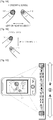
- FIGS. 1A, 1B, and 1C are reference views conceptually illustrating the present invention.
- FIG. 1A illustrates an example of using two fingers to touch a touch screen of a device.
- the device can control a motion of an object according to the pressure difference.
- two fingers are touching the touch screen of the device.
- the device recognizes a touch 100 of a first finger and a touch 110 of a second finger.
- the device determines that the touch 100 of the first finger and the touch 110 of the second finger are arranged horizontally rather than vertically, the object is moved left or right in a direction toward one of the touch 100 of the first finger and the touch 110 of the second finger, depending on which has the higher pressure.
- FIG. 1B illustrates another example of using two fingers to touch a touch screen of a device.
- the device recognizes the touch 100 of the first finger and the touch 110 of the second finger.
- the device determines that the touch 100 of the first finger and the touch 110 of the second finger are arranged vertically rather than horizontally, the object is moved up or down in a direction toward one of the touch 100 of the first finger and the touch 110 of the second finger, depending on which has the higher pressure.
- FIG. 1C illustrates an example of an application when the present invention is embodied in a mobile phone.
- two touches are made on a touch screen of the mobile phone.
- the touch 100 and the touch 110 are arranged vertically rather than horizontally in view of the positional relationship between them so that an object may be moved up or down.
- a pressure of the touch 100 is greater than that of the touch 110, the motion of the object may be controlled to be moved toward the touch 100.
- FIG. 1C which illustrates a vertical scroll
- the scroll may be moved in an upward direction, that is, toward the touch 100, rather the touch 110.
- the positions and inputs of at least two touches on the touch screen in the device including the touch screen are recognized, and thus, the movement of an object may be more intuitively and conveniently controlled.
- FIG. 2 is a schematic block diagram of a motion control apparatus 200 according to an embodiment of the present invention.
- the motion control apparatus 200 includes an input unit 210, a processing unit 220, and a display unit 230.
- the input unit 210 is configured to receive and recognize an input of a user and includes a touch recognition unit 211 and a pressure recognition unit 212 according to the present invention.
- the touch recognition unit 211 recognizes at least two touches on a touch screen and also the positions of the touches.
- the pressure recognition unit 212 is a device that recognizes a pressure at a touch position. Any type of a device capable of recognizing a pressure may be employed as the device for recognizing a pressure in the pressure recognition unit 212.
- a plurality of pressure sensors may be installed to recognize a pressure, or when an area of a touch portion increases by reading the shape of a touch portion in a touch screen, the touch portion may be recognized as one having a high intensity of pressure.
- the intensity of pressure may be recognized by analyzing the strength of a signal generated when a touch occurs on a capacitive touch screen.
- the pressure recognition unit 212 may be embodied by a combination of various technologies for recognizing a touch point and a pressure on the touch screen at the same time.
- the processing unit 220 processes information received from the input unit 210 and controls a movement of an object displayed on the display unit 230 based on a result of the processing.
- the display unit 230 displays the movement of an object under the control of the processing unit 220. Any type of device capable of performing a display function may be employed as the display unit 230.
- an interface may be further provided to transmit a signal received from the input unit 210. That is, the interface preferably transmits information about the position and pressure of a touch on the touch screen to the processing unit 220. Also, a storage unit for storing information or data processed by the processing unit 220 may be further provided.
- FIG. 3 is a flowchart of a motion control method according to an embodiment of the present invention.
- the input unit 210 recognizes the positions and pressures of at least two touches on the touch screen in step 310.
- the touch recognition unit 211 included in the input unit 210 recognizes positions of at least two touches on the touch screen.
- the pressure recognition unit 212 recognizes a pressure at a corresponding touch position.
- the input unit 210 transmits information about the positions and pressures of the at least two recognized touches on the touch screen to the processing unit 220.
- the processing unit 220 controls the movement of an object on the touch screen by using a difference in pressure between at least two recognized positions in step 320.
- the processing unit 220 When receiving the information about the position and pressure of a recognized touch from the input unit 210, the processing unit 220 analyzes information about the position and pressure of the touch, generates a signal to control a movement of an object on a touch screen, and provides the signal to the display unit 230. That is, the processing unit 220 determines a direction of the movement of the object on the touch screen by analyzing information about the positions of the at least two touches recognized on the touch screen. Further, the processing unit 220 determines a speed or strength of the movement of the object on the touch screen by analyzing information about the pressures of the at least two touches recognized on the touch screen.
- a difference in pressure between the two or more touches may not be effective and may not result in a user input according to the motion control method of the present invention.
- a difference between the two pressures may be so small so that the pressures may be regarded as typical inputs occurring when the touch screen is held by two fingers, such as when the user holds the touch screen in a normal manner, rather than as user inputs to which the motion control method of the present invention is to be applied.
- an operation of disregarding such an input may be included because a difference between the two pressures is not a meaningful value.
- the processing unit 220 monitors a pressure difference between the touches of two fingers when a user places fingers on the touch screen in a normal manner, calculates a pressure difference when the device is deemed to be held in a normal manner, and stores a calculated pressure difference as a critical value.
- a pressure difference between two or more touches is analyzed by the motion control method according to the present invention, if the pressure difference is smaller than the stored critical value, the pressure difference is determined as one occurring when a user holds the device in a normal manner, rather than as a user input for motion control so that a signal due to the touch is not used for the motion control of an object.
- the pressure difference between the recognized two or more touches is greater than the critical value, the pressure difference is determined as a user input for motion control, not as one occurring when a user holds the device in a normal manner, so that the motion control of an object may be performed using the pressure difference.
- the critical value can be a predetermined value which is set in the apparatus 200.
- the critical value can be determined to a value of pressure difference between the two or more touches when users normally grab the apparatus 200. Further, it will be possible to adjust the critical value which has been set in the apparatus 200 using an user interface in which the users can change the critical value.
- FIGS. 4A, 4B , and 4C illustrate an embodiment in which movement or deformation of an object on a touch screen is limited to X and Y axes.
- an object 400 is displayed on a touch screen and touches of two fingers are positioned under the object 400.
- the position of a first touch 410 is T1
- the position of a second touch 420 is T2.
- coordinates of T1 are (x1, y1) and coordinates of T2 are (x2, y2)
- ⁇ x is a distance between x2 and x1, that is, a distance on the X axis
- ⁇ y is a distance between y2 and y1, that is, a distance on the Y axis.
- the processing unit 220 determines a movement axis of the object, that is, whether to move the object on the X axis or Y axis. When the distance of the X axis is longer than the distance of the Y axis, the object is determined to be moved on the X axis. When the distance of the Y axis is longer than the distance of the X axis, the object is determined to be moved on the Y axis.
- the processing unit 220 may determine as follows a movement direction of the object, that is, whether to move the object toward T1 or T2, based on a pressure input by the touches of at least two fingers.
- the processing unit 220 may determine as follows a movement speed, that is, pixel movement per hour, of an object. Specifically, the processing unit 220 is preferably determined by a movement speed of an object according to k*
- k denotes a constant determined by the characteristic of an application
- * denotes a multiplication function. That is, when a difference between the two pressures is great, a movement speed is increased. When a difference between the two pressures is small, the movement speed is decreased.
- the processing unit 220 may determine the movement speed of an object according to time. That is, the processing unit 220 may determine the movement speed of an object in proportion to a time t during which a touch is maintained.
- the object is determined to be moved on the X axis. Further, since the pressure of the first touch 410 is greater than that of the second touch 420, the object is determined to be moved toward the first touch 410.
- the fact that the pressure of the first touch 410 is greater than that of the second touch 420 is illustrated by the size of a circle 430 whose center is at the center of the first touch 410 being larger than that of a circle 440 whose center is at the center of the second touch 420, as illustrated in FIG. 4B . Referring to FIG.
- FIGS. 5A, 5B , 5C, 5D, and 5E illustrate examples of specific applications when movement or deformation of an object on a touch screen is generated on the X and Y axes.
- FIG. 5A an example of a vertical scroll is illustrated as a user generates two touches 510 and 520 on a touch screen and creates a difference in pressure, as indicated by the difference in size of touches 510 and 520, between the two touches 510 and 520 in a vertical direction. That is, when the touch screen is touched with two fingers, a scrolling function is performed in an upward direction when a higher pressure is applied to the upper touch 510, and a scrolling function is performed in a downward direction when a higher pressure is applied to the lower touch 520.
- a horizontal scroll may be embodied where a user generates two touches 510 and 520 on a touch screen and creates a difference in pressure between the two touches 510 and 520 in a horizontal direction. That is, when the touch screen is touched with two fingers, a scrolling function is performed to the right when a higher pressure is applied to the right touch 520, and a scrolling function is performed to the left when a higher pressure is applied to the left touch 510.
- an application having a predetermined effect may be embodied, in addition to simple scrolling as illustrated in FIG. 5A or 5B .
- a graphic object is deformed i.e., altered or changed in a direction in which a pressure is applied, thereby producing a sense that the graphic object moves back, which is employed as an effect during scrolling.
- the music or motion picture may be searched for by using the pressure difference between two touches according to the present invention as a search function.
- volume control may be possible by using the pressure difference between two touches according to the present invention.
- FIGS. 6A , 6B, and 6C illustrate an embodiment in which movement or deformation of an object on a touch screen is freely generated without being limited to either the X or Y axes.
- the object may move on the touch screen not only on either the X or Y axis but also in any other direction on the touch screen. For example, an enlarged photo may be panned or a map may be navigated.
- an object 600 is displayed on the touch screen and touches of two fingers are positioned under the object 600.
- the position of a first touch 610 is T1 and the position of a second touch 620 is T2.
- the processing unit 220 can control a movement of an object in any direction, and is not limited to either the X or Y axes, a movement direction is directly determined without determining a movement axis.
- the processing unit 220 may determine as follows the movement direction of an object, that is, whether to move the object toward T1 or T2.
- the processing unit 220 determines as follows a movement speed of the object, that is, pixel movement per hour. That is, the processing unit 220 may determine a movement speed of the object according to k*
- k denotes a constant determined by the characteristic of an application. That is, when a difference between the two pressures is great, a movement speed of the object is increased. When a difference between the two pressures is small, the movement speed of the object is decreased.
- the object may be determined to be moved toward the first touch 610.
- the fact that the pressure of the first touch 610 is greater than that of the second touch 620 is illustrated by the size of a circle 630 whose center is at the center of the first touch 610 being larger than that of a circle 640 whose center is at the center of the second touch 620, as illustrated in FIG. 6B .
- FIG. 6C since the pressure of the second touch 620 is greater than that of the first touch 610, as indicated by the difference in size of a circle as compare to a circle, the object may be determined to be moved toward the second touch 620.
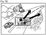
- FIGS. 7A and 7B illustrate an example of specific applications when movement or deformation of an object on a touch screen is freely generated.
- FIG. 7A illustrates an application during a panning operation in a photo.
- a first touch 710 and a second touch 720 are illustrated on a touch screen of a device.
- the photo is panned in a direction toward the second touch 720 having a larger pressure than the first touch 710.
- FIG. 7B illustrates an application of displaying a photo in a device as in FIG. 7A .
- the difference between FIG. 7A and FIG. 7B is that there are three touch points; a) 730, b) 740, and c) 750, on the touch screen.
- a direction of movement of the object may be determined by a vector.
- a method of determining the direction of a movement of an object using a vector is as follows.
- coordinates of a point having the lowest pressure are A0(x0,y0) and coordinates of a point having the highest pressure are An(xn,yn). Also, a pressure value of the point having the lowest point is p0 and a pressure value of a point having the highest pressure is pn.
- the direction of the object may be determined to be (cos ⁇ n, sin ⁇ 0) and the movement speed of the object may be determined to be k*(pn-p0).
- k denotes a constant according to an application.
- the motion of an object is controlled using a difference in pressure between two or more touches on a touch screen in a device, a user is provided with a new interaction experience. Also, since an intuitive and fast operation method is provided to the user, a distinguished function may be provided. Further, an iconic interaction method may be advantageous in terms of product marketing.
- the present invention may be applied to any product having a touch screen, for example, hand held products (HHPs), MP3 players, tablets, personal digital assistants (PDAs), mobile devices, etc.
- HHPs hand held products
- MP3 players MP3 players
- tablets tablets
- PDAs personal digital assistants
- mobile devices etc.
- the invention may also be embodied as computer readable codes on a computer readable recording medium.
- the computer readable recording medium is any non-transitory data storage device that can store data which can be thereafter read by a computer system. Examples of the computer readable recording medium include read-only memory (ROM), random-access memory (RAM), CD-ROMs, magnetic tapes, floppy disks, optical data storage devices, etc.
- the computer readable recording medium may also be distributed over network coupled computer systems so that the computer readable code is stored and executed in a distributed fashion. Also, functional programs, codes, and code segments for accomplishing the present invention may be easily construed by programmers of ordinary skill in the art to which the present invention pertains.
Landscapes
- Engineering & Computer Science (AREA)
- General Engineering & Computer Science (AREA)
- Theoretical Computer Science (AREA)
- Human Computer Interaction (AREA)
- Physics & Mathematics (AREA)
- General Physics & Mathematics (AREA)
- User Interface Of Digital Computer (AREA)
- Position Input By Displaying (AREA)
Description
- The present invention relates generally to a motion control method and apparatus in a touch screen device, and more particularly to a motion control method and apparatus based on differences in positions and pressures on a touch screen.
- A multimodal user interface has become important to increase a user's interaction experience in the use of mobile devices. The spread of multi-touch technology has expanded the market for mobile devices equipped with multi-touch screens.
-
US-2010/026647-A1 discloses an information processing apparatus comprising a touch screen which detects a touch input by a user and detects the position and pressure of each of a plurality of pressed points corresponding to a plurality of touch inputs existing at the same time on a touch screen. Then, the front/rear overlap relationship of the plurality of objects displayed on the touch screen is changed based on the difference in pressure between the detected plurality of pressed points. -
US-6597347-B1 relates to force-sensitive input-control devices with multiple surfaces capable of providing intuitive input in one to thirty-six degrees of freedom. -
EP2237142A1 , citable under Article 54(3) EPC, discloses an information processing apparatus and an estimating method which allow estimation of the pressure values for multiple operation locations on a display screen corresponding to a user operation. - Thus, there is a demand for a user interface that enables users to more intuitively control a motion of an object on a touch-screen of a device.
- The present invention provides a motion control method and apparatus providing a user interface enabling users to more intuitively control motion of an object on a touch-screen device.
- As described above, according to the present invention, since the motion of an object is controlled using a difference in pressure between two or more touches on a touch screen in a device, a user is provided with a new interaction experience. Also, since an intuitive and fast operation method is provided to the user, a distinguished function may be provided. Further, an iconic interaction method may be advantageous in terms of product marketing.
- The above and other features and advantages of the present invention will become more apparent from the following detailed description describing embodiments thereof with reference to the attached drawings in which:
-
FIGS. 1A, 1B, and 1C are reference views conceptually illustrating the present invention; -
FIG. 2 is a schematic block diagram of a motion control apparatus according to an embodiment of the present invention; -
FIG. 3 is a flowchart of a motion control method according to an embodiment of the present invention; -
FIGS. 4A, 4B , and4C illustrate an embodiment in which movement or deformation of an object on a touch screen is limited to X and Y axes; -
FIGS. 5A, 5B ,5C, 5D, and 5E illustrate an example of specific applications when movement or deformation of an object on a touch screen is generated on the X and Y axes; -
FIGS. 6A ,6B, and 6C illustrate a case in which movement or deformation of an object on a touch screen is freely generated without being limited to X and Y axes; and -
FIGS. 7A and7B illustrate an example of specific applications when movement or deformation an object on a touch screen is freely generated. - According to an aspect of the present invention, a method of controlling a motion of an object on a touch screen of a device includes recognizing the intensities of pressures at two positions on the touch screen of the device, and controlling the motion of the object on the touch screen when a difference in intensities of pressure between the two recognized positions is greater than a predetermined value; wherein controlling the motion of the object further comprises: determining a direction of the motion of the object to be toward the position having the highest pressure; characterized in that controlling the motion of the object further comprises: comparing a distance on an X axis with a distance on a Y axis between the two positions; and determining the motion of the object to be in the X axis direction when the distance on the X axis is longer than the distance on the Y axis, and the motion of the object to be in the Y axis direction when the distance on the Y axis is longer than the distance on the X axis.
- According to another aspect of the present invention, an apparatus for controlling a motion of an object on a touch screen of a device includes a recognition unit arranged to recognize intensities of pressures at two positions on the touch screen of the device, and a processing unit arranged to control the motion of the object on the touch screen when a difference in the intensities of pressure between the two positions is greater than a predetermined value, wherein the processing unit is further arranged to determine a direction of the motion of the object to be toward the position having the highest pressure; characterized in that the processing unit is further arranged to compare a distance on an X axis with a distance on a Y axis between the at least two positions, and determines the motion of the object to be in the X axis direction when the distance on the X axis is longer than the distance on the Y axis, and the motion of the object to be in the Y axis direction when the distance on the Y axis is longer than the distance on the X axis.
- The attached drawings illustrate embodiments of the present invention and are referred to in order to gain a sufficient understanding of the present invention, the merits thereof, and the objectives accomplished by the implementation of the present invention. Hereinafter, the present invention will be described in detail by explaining embodiments of the invention with reference to the accompanying drawings. Like reference numerals in the drawings denote like elements described herein.
-
FIGS. 1A, 1B, and 1C are reference views conceptually illustrating the present invention.FIG. 1A illustrates an example of using two fingers to touch a touch screen of a device. When a user touches the touch screen of the device with at least two fingers where there is a difference in pressure between the at least two fingers touching the touch screen, the device can control a motion of an object according to the pressure difference. - Referring to
FIG. 1A , two fingers are touching the touch screen of the device. The device recognizes atouch 100 of a first finger and atouch 110 of a second finger. When the device determines that thetouch 100 of the first finger and thetouch 110 of the second finger are arranged horizontally rather than vertically, the object is moved left or right in a direction toward one of thetouch 100 of the first finger and thetouch 110 of the second finger, depending on which has the higher pressure. -
FIG. 1B illustrates another example of using two fingers to touch a touch screen of a device. Referring toFIG. 1B , the device recognizes thetouch 100 of the first finger and thetouch 110 of the second finger. When the device determines that thetouch 100 of the first finger and thetouch 110 of the second finger are arranged vertically rather than horizontally, the object is moved up or down in a direction toward one of thetouch 100 of the first finger and thetouch 110 of the second finger, depending on which has the higher pressure. -
FIG. 1C illustrates an example of an application when the present invention is embodied in a mobile phone. Referring toFIG. 1C , two touches are made on a touch screen of the mobile phone. Thetouch 100 and thetouch 110 are arranged vertically rather than horizontally in view of the positional relationship between them so that an object may be moved up or down. When a pressure of thetouch 100 is greater than that of thetouch 110, the motion of the object may be controlled to be moved toward thetouch 100. Thus, inFIG. 1C , which illustrates a vertical scroll, the scroll may be moved in an upward direction, that is, toward thetouch 100, rather thetouch 110. According to the present invention, the positions and inputs of at least two touches on the touch screen in the device including the touch screen are recognized, and thus, the movement of an object may be more intuitively and conveniently controlled. -
FIG. 2 is a schematic block diagram of amotion control apparatus 200 according to an embodiment of the present invention. Referring toFIG. 2 , themotion control apparatus 200 includes aninput unit 210, aprocessing unit 220, and adisplay unit 230. - The
input unit 210 is configured to receive and recognize an input of a user and includes atouch recognition unit 211 and apressure recognition unit 212 according to the present invention. Thetouch recognition unit 211 recognizes at least two touches on a touch screen and also the positions of the touches. Thepressure recognition unit 212 is a device that recognizes a pressure at a touch position. Any type of a device capable of recognizing a pressure may be employed as the device for recognizing a pressure in thepressure recognition unit 212. For example, a plurality of pressure sensors may be installed to recognize a pressure, or when an area of a touch portion increases by reading the shape of a touch portion in a touch screen, the touch portion may be recognized as one having a high intensity of pressure. Also, the intensity of pressure may be recognized by analyzing the strength of a signal generated when a touch occurs on a capacitive touch screen. Further, thepressure recognition unit 212 may be embodied by a combination of various technologies for recognizing a touch point and a pressure on the touch screen at the same time. - The
processing unit 220 processes information received from theinput unit 210 and controls a movement of an object displayed on thedisplay unit 230 based on a result of the processing. Thedisplay unit 230 displays the movement of an object under the control of theprocessing unit 220. Any type of device capable of performing a display function may be employed as thedisplay unit 230. - Although not illustrated in
FIG. 2 , an interface may be further provided to transmit a signal received from theinput unit 210. That is, the interface preferably transmits information about the position and pressure of a touch on the touch screen to theprocessing unit 220. Also, a storage unit for storing information or data processed by theprocessing unit 220 may be further provided. -
FIG. 3 is a flowchart of a motion control method according to an embodiment of the present invention. Referring toFIGs. 2 and 3 , theinput unit 210 recognizes the positions and pressures of at least two touches on the touch screen instep 310. Thetouch recognition unit 211 included in theinput unit 210 recognizes positions of at least two touches on the touch screen. Thepressure recognition unit 212 recognizes a pressure at a corresponding touch position. Theinput unit 210 transmits information about the positions and pressures of the at least two recognized touches on the touch screen to theprocessing unit 220. - The
processing unit 220 controls the movement of an object on the touch screen by using a difference in pressure between at least two recognized positions instep 320. - When receiving the information about the position and pressure of a recognized touch from the
input unit 210, theprocessing unit 220 analyzes information about the position and pressure of the touch, generates a signal to control a movement of an object on a touch screen, and provides the signal to thedisplay unit 230. That is, theprocessing unit 220 determines a direction of the movement of the object on the touch screen by analyzing information about the positions of the at least two touches recognized on the touch screen. Further, theprocessing unit 220 determines a speed or strength of the movement of the object on the touch screen by analyzing information about the pressures of the at least two touches recognized on the touch screen. - When pressures due to two or more touches are recognized, a difference in pressure between the two or more touches may not be effective and may not result in a user input according to the motion control method of the present invention. For example, although two pressures are recognized on the touch screen, a difference between the two pressures may be so small so that the pressures may be regarded as typical inputs occurring when the touch screen is held by two fingers, such as when the user holds the touch screen in a normal manner, rather than as user inputs to which the motion control method of the present invention is to be applied. Thus, although it is not illustrated in
FIG. 3 , an operation of disregarding such an input may be included because a difference between the two pressures is not a meaningful value. - Specifically, the
processing unit 220 monitors a pressure difference between the touches of two fingers when a user places fingers on the touch screen in a normal manner, calculates a pressure difference when the device is deemed to be held in a normal manner, and stores a calculated pressure difference as a critical value. When a pressure difference between two or more touches is analyzed by the motion control method according to the present invention, if the pressure difference is smaller than the stored critical value, the pressure difference is determined as one occurring when a user holds the device in a normal manner, rather than as a user input for motion control so that a signal due to the touch is not used for the motion control of an object. If the pressure difference between the recognized two or more touches is greater than the critical value, the pressure difference is determined as a user input for motion control, not as one occurring when a user holds the device in a normal manner, so that the motion control of an object may be performed using the pressure difference. The critical value can be a predetermined value which is set in theapparatus 200. For example, the critical value can be determined to a value of pressure difference between the two or more touches when users normally grab theapparatus 200. Further, it will be possible to adjust the critical value which has been set in theapparatus 200 using an user interface in which the users can change the critical value. The method of analyzing the information about the position and pressure of a touch in theprocessing unit 220 and using the information for motion control of an object on the touch screen is described below in detail with reference to the accompanying drawings. -
FIGS. 4A, 4B , and4C illustrate an embodiment in which movement or deformation of an object on a touch screen is limited to X and Y axes. Examples in which the movement or deformation of an object on a touch screen is limited to X and Y axes, may be a vertical scroll list, a horizontal scroll list, or movement on a progress bar indicating volume or motion picture/music progression. - Referring to
FIG. 4A , anobject 400 is displayed on a touch screen and touches of two fingers are positioned under theobject 400. The position of afirst touch 410 is T1, while the position of asecond touch 420 is T2. When coordinates of T1 are (x1, y1) and coordinates of T2 are (x2, y2), Δx is a distance between x2 and x1, that is, a distance on the X axis, and Δy is a distance between y2 and y1, that is, a distance on the Y axis. - The
processing unit 220 determines a movement axis of the object, that is, whether to move the object on the X axis or Y axis. When the distance of the X axis is longer than the distance of the Y axis, the object is determined to be moved on the X axis. When the distance of the Y axis is longer than the distance of the X axis, the object is determined to be moved on the Y axis. - Also, the
processing unit 220 may determine as follows a movement direction of the object, that is, whether to move the object toward T1 or T2, based on a pressure input by the touches of at least two fingers. - By comparing a pressure P1 (not shown) at T1 with a pressure P2 (not shown) at T2, the object is moved to T1 when P1 is greater than P2, and the object is moved to T2 when P2 is greater than P1. When P1 is the same as P2, the object is not moved.
- Also, the
processing unit 220 may determine as follows a movement speed, that is, pixel movement per hour, of an object. Specifically, theprocessing unit 220 is preferably determined by a movement speed of an object according to k*|P2-P1|. Here, "k" denotes a constant determined by the characteristic of an application, and "*" denotes a multiplication function. That is, when a difference between the two pressures is great, a movement speed is increased. When a difference between the two pressures is small, the movement speed is decreased. - Also, the
processing unit 220 may determine the movement speed of an object according to time. That is, theprocessing unit 220 may determine the movement speed of an object in proportion to a time t during which a touch is maintained. - Referring to
FIG. 4B , since the distance between thefirst touch 410 and thesecond touch 420 on the X axis is longer than that on the Y axis, the object is determined to be moved on the X axis. Further, since the pressure of thefirst touch 410 is greater than that of thesecond touch 420, the object is determined to be moved toward thefirst touch 410. The fact that the pressure of thefirst touch 410 is greater than that of thesecond touch 420 is illustrated by the size of acircle 430 whose center is at the center of thefirst touch 410 being larger than that of acircle 440 whose center is at the center of thesecond touch 420, as illustrated inFIG. 4B . Referring toFIG. 4C , since the distance between thefirst touch 410 and thesecond touch 420 on the Y axis is longer than that on the X axis, the object is moved on the Y axis. Also, since the pressure of thesecond touch 420 is greater than that of thefirst touch 410, as indicated by the difference in size of the circles, the object is determined to be moved toward thesecond touch 420. -
FIGS. 5A, 5B ,5C, 5D, and 5E illustrate examples of specific applications when movement or deformation of an object on a touch screen is generated on the X and Y axes. Referring toFIG. 5A , an example of a vertical scroll is illustrated as a user generates twotouches touches touches upper touch 510, and a scrolling function is performed in a downward direction when a higher pressure is applied to thelower touch 520. - Referring to
FIG. 5B , a horizontal scroll may be embodied where a user generates twotouches touches right touch 520, and a scrolling function is performed to the left when a higher pressure is applied to theleft touch 510. - Referring to
FIG. 5C , an application having a predetermined effect may be embodied, in addition to simple scrolling as illustrated inFIG. 5A or 5B . Specifically, a graphic object is deformed i.e., altered or changed in a direction in which a pressure is applied, thereby producing a sense that the graphic object moves back, which is employed as an effect during scrolling. - Referring to
FIG. 5D , when an application for providing music or a motion picture is executed, the music or motion picture may be searched for by using the pressure difference between two touches according to the present invention as a search function. - Referring to
FIG. 5E , when an application for providing music or a motion picture is executed, volume control may be possible by using the pressure difference between two touches according to the present invention. - In the above description, an example in which the movement of the object on the touch screen is limited to the X and Y axes is described with reference to
FIGS. 4 and5 . -
FIGS. 6A ,6B, and 6C illustrate an embodiment in which movement or deformation of an object on a touch screen is freely generated without being limited to either the X or Y axes. When the movement, deformation, or motion of an object on the touch screen is free, the object may move on the touch screen not only on either the X or Y axis but also in any other direction on the touch screen. For example, an enlarged photo may be panned or a map may be navigated. - Referring to
FIG. 6A , anobject 600 is displayed on the touch screen and touches of two fingers are positioned under theobject 600. The position of afirst touch 610 is T1 and the position of asecond touch 620 is T2. - Since the
processing unit 220 can control a movement of an object in any direction, and is not limited to either the X or Y axes, a movement direction is directly determined without determining a movement axis. Theprocessing unit 220 may determine as follows the movement direction of an object, that is, whether to move the object toward T1 or T2. - By comparing a pressure P1 (not shown) at T1 with a pressure P2 (not shown) at T2, when P1 is greater than P2, the object is determined to be moved toward T1. When P2 is greater than P1, the object is determined to be moved toward T2. When P1 is the same as P2, it is determined that there is no movement of the object.
- Also, the
processing unit 220 determines as follows a movement speed of the object, that is, pixel movement per hour. That is, theprocessing unit 220 may determine a movement speed of the object according to k*|P2-P1|. Here, "k" denotes a constant determined by the characteristic of an application. That is, when a difference between the two pressures is great, a movement speed of the object is increased. When a difference between the two pressures is small, the movement speed of the object is decreased. - Referring to
FIG. 6B , since the pressure of thefirst touch 610 is higher than that of thesecond touch 620 between the first andsecond touches first touch 610. The fact that the pressure of thefirst touch 610 is greater than that of thesecond touch 620 is illustrated by the size of acircle 630 whose center is at the center of thefirst touch 610 being larger than that of acircle 640 whose center is at the center of thesecond touch 620, as illustrated inFIG. 6B . Referring toFIG. 6C , since the pressure of thesecond touch 620 is greater than that of thefirst touch 610, as indicated by the difference in size of a circle as compare to a circle, the object may be determined to be moved toward thesecond touch 620. -
FIGS. 7A and7B illustrate an example of specific applications when movement or deformation of an object on a touch screen is freely generated.FIG. 7A illustrates an application during a panning operation in a photo. Afirst touch 710 and asecond touch 720 are illustrated on a touch screen of a device. The photo is panned in a direction toward thesecond touch 720 having a larger pressure than thefirst touch 710. -
FIG. 7B illustrates an application of displaying a photo in a device as inFIG. 7A . However, the difference betweenFIG. 7A andFIG. 7B is that there are three touch points; a) 730, b) 740, and c) 750, on the touch screen. When pressures due to two or more touches on the touch screen are recognized as inFIG. 7B , a direction of movement of the object may be determined by a vector. - Specifically, a method of determining the direction of a movement of an object using a vector is as follows.
- When a (n+1) number of pressures are recognized on the touch screen, coordinates of a point having the lowest pressure are A0(x0,y0) and coordinates of a point having the highest pressure are An(xn,yn). Also, a pressure value of the point having the lowest point is p0 and a pressure value of a point having the highest pressure is pn.
- According to Equation 1, when the direction of An is n with respect to A0:

- According to Equation 2, when the amount of a pressure is (pn-p0), a vector Fn representing An may be expressed as follows:

- Thus, when pressures due to two or more touches are recognized on the touch screen, the direction of the object may be determined to be (cosθn, sin θ0) and the movement speed of the object may be determined to be k*(pn-p0). Here, "k" denotes a constant according to an application.
- As described above, according to the present invention, since the motion of an object is controlled using a difference in pressure between two or more touches on a touch screen in a device, a user is provided with a new interaction experience. Also, since an intuitive and fast operation method is provided to the user, a distinguished function may be provided. Further, an iconic interaction method may be advantageous in terms of product marketing.
- The present invention may be applied to any product having a touch screen, for example, hand held products (HHPs), MP3 players, tablets, personal digital assistants (PDAs), mobile devices, etc.
- The invention may also be embodied as computer readable codes on a computer readable recording medium. The computer readable recording medium is any non-transitory data storage device that can store data which can be thereafter read by a computer system. Examples of the computer readable recording medium include read-only memory (ROM), random-access memory (RAM), CD-ROMs, magnetic tapes, floppy disks, optical data storage devices, etc. The computer readable recording medium may also be distributed over network coupled computer systems so that the computer readable code is stored and executed in a distributed fashion. Also, functional programs, codes, and code segments for accomplishing the present invention may be easily construed by programmers of ordinary skill in the art to which the present invention pertains.
- While this invention has been particularly shown and described with reference to certain embodiments thereof, it will be understood by those of ordinary skill in the art that various changes in form and details may be made therein without departing from the scope of the invention as defined by the appended claims.
Claims (4)
- A method of controlling a motion of an object on a touch screen of a device, the method comprising:recognizing (310) intensities of pressures at two positions on the touch screen of the device; andcontrolling (320) the motion of the object on the touch screen when a difference in intensities of pressure between the two recognized positions is greater than a predetermined value;wherein controlling (320) the motion of the object further comprises:
determining a direction of the motion of the object to be toward the position having the highest pressure; characterized in that controlling (320) the motion of the object further comprises:comparing a distance on an X axis with a distance on a Y axis between the two positions; anddetermining the motion of the object to be in the X axis direction when the distance on the X axis is longer than the distance on the Y axis, and the motion of the object to be in the Y axis direction when the distance on the Y axis is longer than the distance on the X axis.. - The method of claim 1, wherein controlling the motion of the object further comprises determining a speed of the motion of the object using a difference in intensity of pressure between the two positions.
- An apparatus (200) for controlling a motion of an object on a touch screen of a device, the apparatus comprising:a recognition unit (212) arranged to recognize (310) intensities of pressures at two positions on the touch screen (230) of the device; anda processing unit (211) arranged to control (320) the motion of the object on the touch screen (230) when a difference in the intensities of pressure between the two positions is greater than a predetermined value;wherein the processing unit (220) is further arranged todetermine a direction of the motion of the object to be toward the position having the highest pressure; characterized in that the processing unit (220) is further arranged tocompare a distance on an X axis with a distance on a Y axis between the two positions, anddetermine the motion of the object to be in the X axis direction when the distance on the X axis is longer than the distance on the Y axis, and the motion of the object to be in the Y axis direction when the distance on the Y axis is longer than the distance on the X axis.
- The apparatus (200) of claim 3, wherein the processing unit (220) is further arranged to determine a speed of the motion of the object using a difference in intensity of pressure between the two positions.
Applications Claiming Priority (2)
| Application Number | Priority Date | Filing Date | Title |
|---|---|---|---|
| KR1020100088041A KR101739054B1 (en) | 2010-09-08 | 2010-09-08 | Motion control method and apparatus in a device |
| PCT/KR2011/006627 WO2012033345A1 (en) | 2010-09-08 | 2011-09-07 | Motion control touch screen method and apparatus |
Publications (3)
| Publication Number | Publication Date |
|---|---|
| EP2614422A1 EP2614422A1 (en) | 2013-07-17 |
| EP2614422A4 EP2614422A4 (en) | 2017-01-18 |
| EP2614422B1 true EP2614422B1 (en) | 2018-06-13 |
Family
ID=45770342
Family Applications (1)
| Application Number | Title | Priority Date | Filing Date |
|---|---|---|---|
| EP11823778.3A Not-in-force EP2614422B1 (en) | 2010-09-08 | 2011-09-07 | Motion control touch screen method and apparatus |
Country Status (9)
| Country | Link |
|---|---|
| US (1) | US9684439B2 (en) |
| EP (1) | EP2614422B1 (en) |
| JP (1) | JP2013539580A (en) |
| KR (1) | KR101739054B1 (en) |
| CN (1) | CN103097996B (en) |
| AU (1) | AU2011299695B2 (en) |
| BR (1) | BR112013005483A2 (en) |
| RU (2) | RU2635285C1 (en) |
| WO (1) | WO2012033345A1 (en) |
Families Citing this family (98)
| Publication number | Priority date | Publication date | Assignee | Title |
|---|---|---|---|---|
| DE102011006448A1 (en) | 2010-03-31 | 2011-10-06 | Tk Holdings, Inc. | steering wheel sensors |
| US8587422B2 (en) | 2010-03-31 | 2013-11-19 | Tk Holdings, Inc. | Occupant sensing system |
| JP5759230B2 (en) | 2010-04-02 | 2015-08-05 | ティーケー ホールディングス,インコーポレーテッド | Steering wheel with hand sensor |
| US9285976B2 (en) * | 2011-07-22 | 2016-03-15 | Kddi Corporation | User interface device capable of image scrolling not accompanying finger movement, image scrolling method, and program |
| US9417754B2 (en) | 2011-08-05 | 2016-08-16 | P4tents1, LLC | User interface system, method, and computer program product |
| JP5594910B2 (en) * | 2012-04-09 | 2014-09-24 | 京セラドキュメントソリューションズ株式会社 | Display input device and image forming apparatus having the same |
| WO2013154720A1 (en) | 2012-04-13 | 2013-10-17 | Tk Holdings Inc. | Pressure sensor including a pressure sensitive material for use with control systems and methods of using the same |
| WO2013169865A2 (en) | 2012-05-09 | 2013-11-14 | Yknots Industries Llc | Device, method, and graphical user interface for moving a user interface object based on an intensity of a press input |
| WO2013169845A1 (en) | 2012-05-09 | 2013-11-14 | Yknots Industries Llc | Device, method, and graphical user interface for scrolling nested regions |
| CN109298789B (en) | 2012-05-09 | 2021-12-31 | 苹果公司 | Device, method and graphical user interface for providing feedback on activation status |
| JP6002836B2 (en) | 2012-05-09 | 2016-10-05 | アップル インコーポレイテッド | Device, method, and graphical user interface for transitioning between display states in response to a gesture |
| EP2847660B1 (en) | 2012-05-09 | 2018-11-14 | Apple Inc. | Device, method, and graphical user interface for selecting user interface objects |
| WO2013169851A2 (en) | 2012-05-09 | 2013-11-14 | Yknots Industries Llc | Device, method, and graphical user interface for facilitating user interaction with controls in a user interface |
| WO2013169843A1 (en) | 2012-05-09 | 2013-11-14 | Yknots Industries Llc | Device, method, and graphical user interface for manipulating framed graphical objects |
| JP6273263B2 (en) | 2012-05-09 | 2018-01-31 | アップル インコーポレイテッド | Device, method, and graphical user interface for displaying additional information in response to user contact |
| WO2013169875A2 (en) | 2012-05-09 | 2013-11-14 | Yknots Industries Llc | Device, method, and graphical user interface for displaying content associated with a corresponding affordance |
| WO2013169849A2 (en) | 2012-05-09 | 2013-11-14 | Industries Llc Yknots | Device, method, and graphical user interface for displaying user interface objects corresponding to an application |
| WO2013169882A2 (en) | 2012-05-09 | 2013-11-14 | Yknots Industries Llc | Device, method, and graphical user interface for moving and dropping a user interface object |
| WO2013169842A2 (en) | 2012-05-09 | 2013-11-14 | Yknots Industries Llc | Device, method, and graphical user interface for selecting object within a group of objects |
| CN107977084B (en) | 2012-05-09 | 2021-11-05 | 苹果公司 | Method and apparatus for providing haptic feedback for operations performed in a user interface |
| US20130307788A1 (en) * | 2012-05-16 | 2013-11-21 | Motorola Solutions, Inc. | Device and method for automated use of force sensing touch panels |
| WO2013192539A1 (en) | 2012-06-21 | 2013-12-27 | Nextinput, Inc. | Wafer level mems force dies |
| EP2870445A1 (en) | 2012-07-05 | 2015-05-13 | Ian Campbell | Microelectromechanical load sensor and methods of manufacturing the same |
| JP6260622B2 (en) | 2012-09-17 | 2018-01-17 | ティーケー ホールディングス インク.Tk Holdings Inc. | Single layer force sensor |
| JP6000035B2 (en) * | 2012-09-18 | 2016-09-28 | シャープ株式会社 | Information processing apparatus, information processing apparatus control method, control program, and recording medium |
| JP6163733B2 (en) * | 2012-11-09 | 2017-07-19 | オムロン株式会社 | Control device and control program |
| CN103809776B (en) * | 2012-11-12 | 2017-05-24 | 联想(北京)有限公司 | Function execution method and electronic equipment |
| CN102984569A (en) * | 2012-11-29 | 2013-03-20 | 中兴通讯股份有限公司 | Method, device and system for controlling television interface focus |
| EP2742869A1 (en) * | 2012-12-12 | 2014-06-18 | Samsung Medison Co., Ltd. | Ultrasound apparatus and method of inputting information into the same |
| WO2014094283A1 (en) * | 2012-12-20 | 2014-06-26 | Intel Corporation | Touchscreen including force sensors |
| JP6158947B2 (en) | 2012-12-29 | 2017-07-05 | アップル インコーポレイテッド | Device, method and graphical user interface for transitioning between relationships from touch input to display output |
| EP2939096B1 (en) | 2012-12-29 | 2019-08-28 | Apple Inc. | Device, method, and graphical user interface for determining whether to scroll or select contents |
| WO2014105275A1 (en) | 2012-12-29 | 2014-07-03 | Yknots Industries Llc | Device, method, and graphical user interface for forgoing generation of tactile output for a multi-contact gesture |
| KR101742808B1 (en) | 2012-12-29 | 2017-06-01 | 애플 인크. | Device, method, and graphical user interface for navigating user interface hierachies |
| CN105144057B (en) | 2012-12-29 | 2019-05-17 | 苹果公司 | Apparatus, method, and graphical user interface for moving a cursor based on changes in appearance of a control icon having simulated three-dimensional features |
| WO2014105279A1 (en) | 2012-12-29 | 2014-07-03 | Yknots Industries Llc | Device, method, and graphical user interface for switching between user interfaces |
| CN103116467B (en) * | 2013-03-07 | 2017-03-01 | 东蓝数码有限公司 | Based on the video progress of multi-point touch and the control method of volume |
| US20140300543A1 (en) * | 2013-04-05 | 2014-10-09 | Itvers Co., Ltd. | Touch pad input method and input device |
| CN103257825B (en) * | 2013-04-28 | 2016-03-30 | 小米科技有限责任公司 | A kind of method and apparatus regulating playing progress rate |
| US9109921B1 (en) * | 2013-06-19 | 2015-08-18 | Amazon Technologies, Inc. | Contextual based navigation element |
| US9665206B1 (en) | 2013-09-18 | 2017-05-30 | Apple Inc. | Dynamic user interface adaptable to multiple input tools |
| JP6150712B2 (en) * | 2013-10-30 | 2017-06-21 | シャープ株式会社 | Information processing apparatus and program |
| KR20150051278A (en) * | 2013-11-01 | 2015-05-12 | 삼성전자주식회사 | Object moving method and electronic device implementing the same |
| CN105934661B (en) | 2014-01-13 | 2019-11-05 | 触控解决方案股份有限公司 | Miniature Reinforced Wafer-Scale MEMS Force Sensor |
| JP2015148972A (en) * | 2014-02-07 | 2015-08-20 | 株式会社コルグ | Touch panel device |
| US20170131824A1 (en) * | 2014-03-20 | 2017-05-11 | Nec Corporation | Information processing apparatus, information processing method, and information processing program |
| US9904417B2 (en) * | 2014-04-16 | 2018-02-27 | Microchip Technology Incorporated | Projected capacitive touch detection with touch force detection using self-capacitance and mutual capacitance detection |
| US9645732B2 (en) | 2015-03-08 | 2017-05-09 | Apple Inc. | Devices, methods, and graphical user interfaces for displaying and using menus |
| US10095396B2 (en) | 2015-03-08 | 2018-10-09 | Apple Inc. | Devices, methods, and graphical user interfaces for interacting with a control object while dragging another object |
| US9632664B2 (en) | 2015-03-08 | 2017-04-25 | Apple Inc. | Devices, methods, and graphical user interfaces for manipulating user interface objects with visual and/or haptic feedback |
| US10048757B2 (en) | 2015-03-08 | 2018-08-14 | Apple Inc. | Devices and methods for controlling media presentation |
| US9990107B2 (en) | 2015-03-08 | 2018-06-05 | Apple Inc. | Devices, methods, and graphical user interfaces for displaying and using menus |
| US9639184B2 (en) | 2015-03-19 | 2017-05-02 | Apple Inc. | Touch input cursor manipulation |
| US9785305B2 (en) | 2015-03-19 | 2017-10-10 | Apple Inc. | Touch input cursor manipulation |
| US9791956B2 (en) * | 2015-03-30 | 2017-10-17 | Lenovo (Singapore) Pte. Ltd. | Touch panel click action |
| US20170045981A1 (en) | 2015-08-10 | 2017-02-16 | Apple Inc. | Devices and Methods for Processing Touch Inputs Based on Their Intensities |
| US10067653B2 (en) | 2015-04-01 | 2018-09-04 | Apple Inc. | Devices and methods for processing touch inputs based on their intensities |
| JP2016224919A (en) * | 2015-06-01 | 2016-12-28 | キヤノン株式会社 | Data browsing device, data browsing method, and program |
| CN106293438A (en) * | 2015-06-04 | 2017-01-04 | 北京智谷睿拓技术服务有限公司 | Method of mapping, device and subscriber equipment |
| US9830048B2 (en) | 2015-06-07 | 2017-11-28 | Apple Inc. | Devices and methods for processing touch inputs with instructions in a web page |
| US9891811B2 (en) | 2015-06-07 | 2018-02-13 | Apple Inc. | Devices and methods for navigating between user interfaces |
| US9674426B2 (en) | 2015-06-07 | 2017-06-06 | Apple Inc. | Devices and methods for capturing and interacting with enhanced digital images |
| US10346030B2 (en) | 2015-06-07 | 2019-07-09 | Apple Inc. | Devices and methods for navigating between user interfaces |
| US9860451B2 (en) | 2015-06-07 | 2018-01-02 | Apple Inc. | Devices and methods for capturing and interacting with enhanced digital images |
| US10200598B2 (en) | 2015-06-07 | 2019-02-05 | Apple Inc. | Devices and methods for capturing and interacting with enhanced digital images |
| EP3307671B1 (en) | 2015-06-10 | 2022-06-15 | Nextinput, Inc. | Ruggedized wafer level mems force sensor with a tolerance trench |
| US10235035B2 (en) | 2015-08-10 | 2019-03-19 | Apple Inc. | Devices, methods, and graphical user interfaces for content navigation and manipulation |
| US9880735B2 (en) | 2015-08-10 | 2018-01-30 | Apple Inc. | Devices, methods, and graphical user interfaces for manipulating user interface objects with visual and/or haptic feedback |
| US10248308B2 (en) | 2015-08-10 | 2019-04-02 | Apple Inc. | Devices, methods, and graphical user interfaces for manipulating user interfaces with physical gestures |
| US10416800B2 (en) | 2015-08-10 | 2019-09-17 | Apple Inc. | Devices, methods, and graphical user interfaces for adjusting user interface objects |
| CN106293446B (en) * | 2015-08-18 | 2020-03-03 | 北京智谷睿拓技术服务有限公司 | Display method and display device |
| CN106293447B (en) * | 2015-08-18 | 2020-10-30 | 北京智谷睿拓技术服务有限公司 | Display method and display device |
| CN106371646B (en) * | 2015-08-18 | 2019-04-30 | 北京智谷睿拓技术服务有限公司 | Display methods and display equipment |
| CN106371690A (en) * | 2015-08-18 | 2017-02-01 | 北京智谷睿拓技术服务有限公司 | Region determination method and apparatus, and display device |
| CN106371716A (en) * | 2015-08-25 | 2017-02-01 | 北京智谷睿拓技术服务有限公司 | Search method, search device and user equipment |
| CN106371741B (en) * | 2015-08-25 | 2019-11-29 | 北京智谷睿拓技术服务有限公司 | Sort method, collator and user equipment |
| US10656746B2 (en) | 2015-09-18 | 2020-05-19 | Sony Corporation | Information processing device, information processing method, and program |
| JP2018022438A (en) * | 2016-08-05 | 2018-02-08 | ソニー株式会社 | Information processing apparatus, information processing method, and program |
| CN107992259A (en) * | 2016-10-27 | 2018-05-04 | 中兴通讯股份有限公司 | The definite method and device of kinematic parameter |
| CN106843572A (en) * | 2016-12-30 | 2017-06-13 | 上海创功通讯技术有限公司 | Mobile terminal and its control method |
| CN110494724B (en) | 2017-02-09 | 2023-08-01 | 触控解决方案股份有限公司 | Integrated digital force sensor and related manufacturing method |
| WO2018148510A1 (en) | 2017-02-09 | 2018-08-16 | Nextinput, Inc. | Integrated piezoresistive and piezoelectric fusion force sensor |
| CN108693990A (en) * | 2017-04-12 | 2018-10-23 | 中兴通讯股份有限公司 | A kind of terminal touch screen exchange method and device |
| CN109213349A (en) * | 2017-06-30 | 2019-01-15 | 北京小米移动软件有限公司 | Exchange method and device, computer readable storage medium based on touch screen |
| WO2019018641A1 (en) | 2017-07-19 | 2019-01-24 | Nextinput, Inc. | Strain transfer stacking in a mems force sensor |
| US11423686B2 (en) | 2017-07-25 | 2022-08-23 | Qorvo Us, Inc. | Integrated fingerprint and force sensor |
| WO2019023552A1 (en) | 2017-07-27 | 2019-01-31 | Nextinput, Inc. | A wafer bonded piezoresistive and piezoelectric force sensor and related methods of manufacture |
| US11579028B2 (en) | 2017-10-17 | 2023-02-14 | Nextinput, Inc. | Temperature coefficient of offset compensation for force sensor and strain gauge |
| WO2019090057A1 (en) | 2017-11-02 | 2019-05-09 | Nextinput, Inc. | Sealed force sensor with etch stop layer |
| WO2019099821A1 (en) | 2017-11-16 | 2019-05-23 | Nextinput, Inc. | Force attenuator for force sensor |
| US10871848B2 (en) | 2018-09-13 | 2020-12-22 | Sensel, Inc. | Method and apparatus for variable impedence touch sensor array gesture recognition |
| US10990223B2 (en) | 2018-09-13 | 2021-04-27 | Sensel, Inc. | Method and apparatus for variable impedence touch sensor array force aware interaction in large surface devices |
| US10891050B2 (en) | 2018-09-13 | 2021-01-12 | Sensel, Inc. | Method and apparatus for variable impedance touch sensor arrays in non-planar controls |
| US11003274B2 (en) | 2018-09-13 | 2021-05-11 | Sensel, Inc. | Method and apparatus for automotive variable impedance touch sensor array |
| JP6606591B2 (en) * | 2018-10-19 | 2019-11-13 | シャープ株式会社 | Touch panel device and image display method |
| US11513648B2 (en) * | 2018-12-26 | 2022-11-29 | Sensel, Inc. | Method and apparatus for variable impedance touch sensor array force aware interaction with handheld display devices |
| WO2020142311A1 (en) | 2019-01-03 | 2020-07-09 | Sensel, Inc. | Method and apparatus for indirect force aware touch control with variable impedance touch sensor arrays |
| US10962427B2 (en) | 2019-01-10 | 2021-03-30 | Nextinput, Inc. | Slotted MEMS force sensor |
Family Cites Families (37)
| Publication number | Priority date | Publication date | Assignee | Title |
|---|---|---|---|---|
| US4056713A (en) * | 1976-10-01 | 1977-11-01 | Digital Equipment Corporation | Display processing unit for drawing vectors |
| USRE40891E1 (en) * | 1991-11-26 | 2009-09-01 | Sandio Technology Corp. | Methods and apparatus for providing touch-sensitive input in multiple degrees of freedom |
| US6597347B1 (en) * | 1991-11-26 | 2003-07-22 | Itu Research Inc. | Methods and apparatus for providing touch-sensitive input in multiple degrees of freedom |
| US5565887A (en) * | 1994-06-29 | 1996-10-15 | Microsoft Corporation | Method and apparatus for moving a cursor on a computer screen |
| JP4803883B2 (en) * | 2000-01-31 | 2011-10-26 | キヤノン株式会社 | Position information processing apparatus and method and program thereof. |
| US7138983B2 (en) | 2000-01-31 | 2006-11-21 | Canon Kabushiki Kaisha | Method and apparatus for detecting and interpreting path of designated position |
| US6980201B1 (en) * | 2000-09-29 | 2005-12-27 | Rockwell Automation Technologies, Inc. | Minimum move touch plane scanning method and device |
| RU2324218C2 (en) * | 2002-09-09 | 2008-05-10 | Сони Эрикссон Мобайл Коммьюникейшнз Аб | Input device for touch-screen |
| US8325143B2 (en) * | 2003-07-21 | 2012-12-04 | Creator Technology B.V. | Touch sensitive display for a portable device |
| US7724242B2 (en) | 2004-08-06 | 2010-05-25 | Touchtable, Inc. | Touch driven method and apparatus to integrate and display multiple image layers forming alternate depictions of same subject matter |
| US7331245B2 (en) * | 2005-11-22 | 2008-02-19 | Avago Technologies Ecbu Ip Pte Ltd | Pressure distribution sensor and sensing method |
| KR100686562B1 (en) * | 2005-12-02 | 2007-02-26 | 유대성 | Screen operation device of electronic device |
| KR100694989B1 (en) * | 2005-12-28 | 2007-03-14 | 엘지전자 주식회사 | Mouse pointer control method of mobile communication terminal and mobile communication terminal |
| US7907125B2 (en) * | 2007-01-05 | 2011-03-15 | Microsoft Corporation | Recognizing multiple input point gestures |
| US8368653B2 (en) | 2007-01-31 | 2013-02-05 | Perceptive Pixel, Inc. | Methods of interfacing with multi-point input devices and multi-point input systems employing interfacing techniques |
| KR100950234B1 (en) * | 2007-07-06 | 2010-03-29 | 한국표준과학연구원 | Implementation method of mouse algorithm using pressure sensor |
| US8619038B2 (en) | 2007-09-04 | 2013-12-31 | Apple Inc. | Editing interface |
| US8358226B2 (en) * | 2007-10-28 | 2013-01-22 | Synaptics Incorporated | Determining actuation of multi-sensor-electrode capacitive buttons |
| WO2009072848A2 (en) * | 2007-12-05 | 2009-06-11 | Eui Jin Oh | Data input device |
| WO2009110769A2 (en) * | 2008-03-06 | 2009-09-11 | Oh Eui-Jin | Data input device |
| US20090237374A1 (en) * | 2008-03-20 | 2009-09-24 | Motorola, Inc. | Transparent pressure sensor and method for using |
| KR101496844B1 (en) * | 2008-07-28 | 2015-02-27 | 삼성디스플레이 주식회사 | Touch screen display device and driving method thereof |
| JP5100556B2 (en) * | 2008-07-30 | 2012-12-19 | キヤノン株式会社 | Information processing method and apparatus |
| US20100039393A1 (en) * | 2008-08-15 | 2010-02-18 | At&T Intellectual Property I, L.P. | Text entry on touch screen cellphones by different pressure levels |
| WO2010036050A2 (en) * | 2008-09-26 | 2010-04-01 | Lg Electronics Inc. | Mobile terminal and control method thereof |
| JP5228755B2 (en) * | 2008-09-29 | 2013-07-03 | 富士通株式会社 | Portable terminal device, display control method, and display control program |
| JP2010086230A (en) * | 2008-09-30 | 2010-04-15 | Sony Corp | Information processing apparatus, information processing method and program |
| US8957865B2 (en) * | 2009-01-05 | 2015-02-17 | Apple Inc. | Device, method, and graphical user interface for manipulating a user interface object |
| JP2010176332A (en) | 2009-01-28 | 2010-08-12 | Sony Corp | Information processing apparatus, information processing method, and program |
| KR101587002B1 (en) * | 2009-02-02 | 2016-01-20 | 삼성전자주식회사 | Input device of portable terminal and method thereof |
| JP5232034B2 (en) * | 2009-02-06 | 2013-07-10 | アルプス電気株式会社 | Input processing device |
| JP5146389B2 (en) * | 2009-04-03 | 2013-02-20 | ソニー株式会社 | Information processing apparatus and estimation method |
| US8723988B2 (en) * | 2009-07-17 | 2014-05-13 | Sony Corporation | Using a touch sensitive display to control magnification and capture of digital images by an electronic device |
| US9740340B1 (en) * | 2009-07-31 | 2017-08-22 | Amazon Technologies, Inc. | Visually consistent arrays including conductive mesh |
| US8363020B2 (en) * | 2009-08-27 | 2013-01-29 | Symbol Technologies, Inc. | Methods and apparatus for pressure-based manipulation of content on a touch screen |
| US9489073B2 (en) * | 2009-12-21 | 2016-11-08 | Promethean Limited | Multi-point contacts with pressure data on an interactive surface |
| US8686960B2 (en) * | 2010-04-23 | 2014-04-01 | Lester F. Ludwig | Piecewise-linear and piecewise-affine transformations for high dimensional touchpad (HDTP) output decoupling and corrections |
-
2010
- 2010-09-08 KR KR1020100088041A patent/KR101739054B1/en not_active Expired - Fee Related
-
2011
- 2011-09-07 WO PCT/KR2011/006627 patent/WO2012033345A1/en not_active Ceased
- 2011-09-07 BR BR112013005483A patent/BR112013005483A2/en not_active IP Right Cessation
- 2011-09-07 CN CN201180043297.4A patent/CN103097996B/en not_active Expired - Fee Related
- 2011-09-07 JP JP2013528117A patent/JP2013539580A/en not_active Ceased
- 2011-09-07 RU RU2015144389A patent/RU2635285C1/en not_active IP Right Cessation
- 2011-09-07 EP EP11823778.3A patent/EP2614422B1/en not_active Not-in-force
- 2011-09-07 RU RU2013115304/08A patent/RU2013115304A/en unknown
- 2011-09-07 AU AU2011299695A patent/AU2011299695B2/en not_active Ceased
- 2011-09-08 US US13/228,059 patent/US9684439B2/en not_active Expired - Fee Related
Non-Patent Citations (1)
| Title |
|---|
| None * |
Also Published As
| Publication number | Publication date |
|---|---|
| CN103097996B (en) | 2016-09-07 |
| KR20120060259A (en) | 2012-06-12 |
| BR112013005483A2 (en) | 2016-05-03 |
| JP2013539580A (en) | 2013-10-24 |
| WO2012033345A1 (en) | 2012-03-15 |
| US9684439B2 (en) | 2017-06-20 |
| EP2614422A1 (en) | 2013-07-17 |
| AU2011299695B2 (en) | 2015-05-21 |
| RU2635285C1 (en) | 2017-11-09 |
| KR101739054B1 (en) | 2017-05-24 |
| EP2614422A4 (en) | 2017-01-18 |
| CN103097996A (en) | 2013-05-08 |
| US20120056837A1 (en) | 2012-03-08 |
| AU2011299695A1 (en) | 2013-03-21 |
| RU2013115304A (en) | 2014-10-20 |
Similar Documents
| Publication | Publication Date | Title |
|---|---|---|
| US9684439B2 (en) | Motion control touch screen method and apparatus | |
| US20220179500A1 (en) | Motion detecting system having multiple sensors | |
| JP6370893B2 (en) | System and method for performing device actions based on detected gestures | |
| US7849421B2 (en) | Virtual mouse driving apparatus and method using two-handed gestures | |
| EP2628067B1 (en) | Apparatus and method for controlling motion-based user interface | |
| KR101502659B1 (en) | Gesture recognition method and touch system incorporating the same | |
| US10564759B2 (en) | Method and apparatus for providing touch interface | |
| US10042438B2 (en) | Systems and methods for text entry | |
| EP3343341B1 (en) | Touch input method through edge screen, and electronic device | |
| EP2270630A2 (en) | Gesture recognition method and touch system incorporating the same | |
| KR20150056074A (en) | Electronic apparatus and method for screen sharing with external display apparatus | |
| US9639167B2 (en) | Control method of electronic apparatus having non-contact gesture sensitive region | |
| CN102915183A (en) | Multi-cell selection using touch input | |
| US20120007826A1 (en) | Touch-controlled electric apparatus and control method thereof | |
| CN105744054A (en) | Mobile terminal control method and mobile terminal | |
| US20180018084A1 (en) | Display device, display method and computer-readable recording medium | |
| US10042445B1 (en) | Adaptive display of user interface elements based on proximity sensing | |
| KR20160097410A (en) | Method of providing touchless input interface based on gesture recognition and the apparatus applied thereto | |
| US10078443B2 (en) | Control system for virtual mouse and control method thereof | |
| KR20150094967A (en) | Electro device executing at least one application and method for controlling thereof | |
| US9285915B2 (en) | Method of touch command integration and touch system using the same | |
| JP5812582B2 (en) | Information processing apparatus and information processing method | |
| US20110119579A1 (en) | Method of turning over three-dimensional graphic object by use of touch sensitive input device | |
| US20120245741A1 (en) | Information processing apparatus, information processing method, recording medium, and program | |
| US11287897B2 (en) | Motion detecting system having multiple sensors |
Legal Events
| Date | Code | Title | Description |
|---|---|---|---|
| PUAI | Public reference made under article 153(3) epc to a published international application that has entered the european phase |
Free format text: ORIGINAL CODE: 0009012 |
|
| 17P | Request for examination filed |
Effective date: 20130403 |
|
| AK | Designated contracting states |
Kind code of ref document: A1 Designated state(s): AL AT BE BG CH CY CZ DE DK EE ES FI FR GB GR HR HU IE IS IT LI LT LU LV MC MK MT NL NO PL PT RO RS SE SI SK SM TR |
|
| DAX | Request for extension of the european patent (deleted) | ||
| REG | Reference to a national code |
Ref country code: DE Ref legal event code: R079 Ref document number: 602011049302 Country of ref document: DE Free format text: PREVIOUS MAIN CLASS: G06F0003041000 Ipc: G06F0003048800 |
|
| RA4 | Supplementary search report drawn up and despatched (corrected) |
Effective date: 20161220 |
|
| RIC1 | Information provided on ipc code assigned before grant |
Ipc: G06F 3/0485 20130101ALI20161214BHEP Ipc: G06F 3/041 20060101ALI20161214BHEP Ipc: G06F 3/0488 20130101AFI20161214BHEP Ipc: G06F 3/0484 20130101ALI20161214BHEP |
|
| STAA | Information on the status of an ep patent application or granted ep patent |
Free format text: STATUS: EXAMINATION IS IN PROGRESS |
|
| 17Q | First examination report despatched |
Effective date: 20170928 |
|
| GRAP | Despatch of communication of intention to grant a patent |
Free format text: ORIGINAL CODE: EPIDOSNIGR1 |
|
| STAA | Information on the status of an ep patent application or granted ep patent |
Free format text: STATUS: GRANT OF PATENT IS INTENDED |
|
| INTG | Intention to grant announced |
Effective date: 20180206 |
|
| GRAS | Grant fee paid |
Free format text: ORIGINAL CODE: EPIDOSNIGR3 |
|
| GRAA | (expected) grant |
Free format text: ORIGINAL CODE: 0009210 |
|
| STAA | Information on the status of an ep patent application or granted ep patent |
Free format text: STATUS: THE PATENT HAS BEEN GRANTED |
|
| AK | Designated contracting states |
Kind code of ref document: B1 Designated state(s): AL AT BE BG CH CY CZ DE DK EE ES FI FR GB GR HR HU IE IS IT LI LT LU LV MC MK MT NL NO PL PT RO RS SE SI SK SM TR |
|
| REG | Reference to a national code |
Ref country code: GB Ref legal event code: FG4D |
|
| REG | Reference to a national code |
Ref country code: CH Ref legal event code: EP Ref country code: AT Ref legal event code: REF Ref document number: 1009146 Country of ref document: AT Kind code of ref document: T Effective date: 20180615 |
|
| REG | Reference to a national code |
Ref country code: IE Ref legal event code: FG4D |
|
| REG | Reference to a national code |
Ref country code: DE Ref legal event code: R096 Ref document number: 602011049302 Country of ref document: DE |
|
| REG | Reference to a national code |
Ref country code: NL Ref legal event code: FP |
|
| REG | Reference to a national code |
Ref country code: LT Ref legal event code: MG4D |
|
| PG25 | Lapsed in a contracting state [announced via postgrant information from national office to epo] |
Ref country code: FI Free format text: LAPSE BECAUSE OF FAILURE TO SUBMIT A TRANSLATION OF THE DESCRIPTION OR TO PAY THE FEE WITHIN THE PRESCRIBED TIME-LIMIT Effective date: 20180613 Ref country code: BG Free format text: LAPSE BECAUSE OF FAILURE TO SUBMIT A TRANSLATION OF THE DESCRIPTION OR TO PAY THE FEE WITHIN THE PRESCRIBED TIME-LIMIT Effective date: 20180913 Ref country code: CY Free format text: LAPSE BECAUSE OF FAILURE TO SUBMIT A TRANSLATION OF THE DESCRIPTION OR TO PAY THE FEE WITHIN THE PRESCRIBED TIME-LIMIT Effective date: 20180613 Ref country code: LT Free format text: LAPSE BECAUSE OF FAILURE TO SUBMIT A TRANSLATION OF THE DESCRIPTION OR TO PAY THE FEE WITHIN THE PRESCRIBED TIME-LIMIT Effective date: 20180613 Ref country code: SE Free format text: LAPSE BECAUSE OF FAILURE TO SUBMIT A TRANSLATION OF THE DESCRIPTION OR TO PAY THE FEE WITHIN THE PRESCRIBED TIME-LIMIT Effective date: 20180613 Ref country code: NO Free format text: LAPSE BECAUSE OF FAILURE TO SUBMIT A TRANSLATION OF THE DESCRIPTION OR TO PAY THE FEE WITHIN THE PRESCRIBED TIME-LIMIT Effective date: 20180913 Ref country code: ES Free format text: LAPSE BECAUSE OF FAILURE TO SUBMIT A TRANSLATION OF THE DESCRIPTION OR TO PAY THE FEE WITHIN THE PRESCRIBED TIME-LIMIT Effective date: 20180613 |
|
| PG25 | Lapsed in a contracting state [announced via postgrant information from national office to epo] |
Ref country code: RS Free format text: LAPSE BECAUSE OF FAILURE TO SUBMIT A TRANSLATION OF THE DESCRIPTION OR TO PAY THE FEE WITHIN THE PRESCRIBED TIME-LIMIT Effective date: 20180613 Ref country code: LV Free format text: LAPSE BECAUSE OF FAILURE TO SUBMIT A TRANSLATION OF THE DESCRIPTION OR TO PAY THE FEE WITHIN THE PRESCRIBED TIME-LIMIT Effective date: 20180613 Ref country code: GR Free format text: LAPSE BECAUSE OF FAILURE TO SUBMIT A TRANSLATION OF THE DESCRIPTION OR TO PAY THE FEE WITHIN THE PRESCRIBED TIME-LIMIT Effective date: 20180914 Ref country code: HR Free format text: LAPSE BECAUSE OF FAILURE TO SUBMIT A TRANSLATION OF THE DESCRIPTION OR TO PAY THE FEE WITHIN THE PRESCRIBED TIME-LIMIT Effective date: 20180613 |
|
| REG | Reference to a national code |
Ref country code: AT Ref legal event code: MK05 Ref document number: 1009146 Country of ref document: AT Kind code of ref document: T Effective date: 20180613 |
|
| PG25 | Lapsed in a contracting state [announced via postgrant information from national office to epo] |
Ref country code: SK Free format text: LAPSE BECAUSE OF FAILURE TO SUBMIT A TRANSLATION OF THE DESCRIPTION OR TO PAY THE FEE WITHIN THE PRESCRIBED TIME-LIMIT Effective date: 20180613 Ref country code: EE Free format text: LAPSE BECAUSE OF FAILURE TO SUBMIT A TRANSLATION OF THE DESCRIPTION OR TO PAY THE FEE WITHIN THE PRESCRIBED TIME-LIMIT Effective date: 20180613 Ref country code: PL Free format text: LAPSE BECAUSE OF FAILURE TO SUBMIT A TRANSLATION OF THE DESCRIPTION OR TO PAY THE FEE WITHIN THE PRESCRIBED TIME-LIMIT Effective date: 20180613 Ref country code: RO Free format text: LAPSE BECAUSE OF FAILURE TO SUBMIT A TRANSLATION OF THE DESCRIPTION OR TO PAY THE FEE WITHIN THE PRESCRIBED TIME-LIMIT Effective date: 20180613 Ref country code: CZ Free format text: LAPSE BECAUSE OF FAILURE TO SUBMIT A TRANSLATION OF THE DESCRIPTION OR TO PAY THE FEE WITHIN THE PRESCRIBED TIME-LIMIT Effective date: 20180613 Ref country code: AT Free format text: LAPSE BECAUSE OF FAILURE TO SUBMIT A TRANSLATION OF THE DESCRIPTION OR TO PAY THE FEE WITHIN THE PRESCRIBED TIME-LIMIT Effective date: 20180613 Ref country code: IS Free format text: LAPSE BECAUSE OF FAILURE TO SUBMIT A TRANSLATION OF THE DESCRIPTION OR TO PAY THE FEE WITHIN THE PRESCRIBED TIME-LIMIT Effective date: 20181013 |
|
| PG25 | Lapsed in a contracting state [announced via postgrant information from national office to epo] |
Ref country code: IT Free format text: LAPSE BECAUSE OF FAILURE TO SUBMIT A TRANSLATION OF THE DESCRIPTION OR TO PAY THE FEE WITHIN THE PRESCRIBED TIME-LIMIT Effective date: 20180613 Ref country code: SM Free format text: LAPSE BECAUSE OF FAILURE TO SUBMIT A TRANSLATION OF THE DESCRIPTION OR TO PAY THE FEE WITHIN THE PRESCRIBED TIME-LIMIT Effective date: 20180613 |
|
| REG | Reference to a national code |
Ref country code: DE Ref legal event code: R097 Ref document number: 602011049302 Country of ref document: DE |
|
| PLBE | No opposition filed within time limit |
Free format text: ORIGINAL CODE: 0009261 |
|
| STAA | Information on the status of an ep patent application or granted ep patent |
Free format text: STATUS: NO OPPOSITION FILED WITHIN TIME LIMIT |
|
| PG25 | Lapsed in a contracting state [announced via postgrant information from national office to epo] |
Ref country code: MC Free format text: LAPSE BECAUSE OF FAILURE TO SUBMIT A TRANSLATION OF THE DESCRIPTION OR TO PAY THE FEE WITHIN THE PRESCRIBED TIME-LIMIT Effective date: 20180613 |
|
| REG | Reference to a national code |
Ref country code: CH Ref legal event code: PL |
|
| 26N | No opposition filed |
Effective date: 20190314 |
|
| PG25 | Lapsed in a contracting state [announced via postgrant information from national office to epo] |
Ref country code: DK Free format text: LAPSE BECAUSE OF FAILURE TO SUBMIT A TRANSLATION OF THE DESCRIPTION OR TO PAY THE FEE WITHIN THE PRESCRIBED TIME-LIMIT Effective date: 20180613 Ref country code: SI Free format text: LAPSE BECAUSE OF FAILURE TO SUBMIT A TRANSLATION OF THE DESCRIPTION OR TO PAY THE FEE WITHIN THE PRESCRIBED TIME-LIMIT Effective date: 20180613 |
|
| REG | Reference to a national code |
Ref country code: BE Ref legal event code: MM Effective date: 20180930 |
|
| REG | Reference to a national code |
Ref country code: IE Ref legal event code: MM4A |
|
| PG25 | Lapsed in a contracting state [announced via postgrant information from national office to epo] |
Ref country code: LU Free format text: LAPSE BECAUSE OF NON-PAYMENT OF DUE FEES Effective date: 20180907 |
|
| PG25 | Lapsed in a contracting state [announced via postgrant information from national office to epo] |
Ref country code: IE Free format text: LAPSE BECAUSE OF NON-PAYMENT OF DUE FEES Effective date: 20180907 |
|
| PG25 | Lapsed in a contracting state [announced via postgrant information from national office to epo] |
Ref country code: FR Free format text: LAPSE BECAUSE OF NON-PAYMENT OF DUE FEES Effective date: 20180930 Ref country code: BE Free format text: LAPSE BECAUSE OF NON-PAYMENT OF DUE FEES Effective date: 20180930 Ref country code: CH Free format text: LAPSE BECAUSE OF NON-PAYMENT OF DUE FEES Effective date: 20180930 Ref country code: LI Free format text: LAPSE BECAUSE OF NON-PAYMENT OF DUE FEES Effective date: 20180930 |
|
| PG25 | Lapsed in a contracting state [announced via postgrant information from national office to epo] |
Ref country code: AL Free format text: LAPSE BECAUSE OF FAILURE TO SUBMIT A TRANSLATION OF THE DESCRIPTION OR TO PAY THE FEE WITHIN THE PRESCRIBED TIME-LIMIT Effective date: 20180613 |
|
| PG25 | Lapsed in a contracting state [announced via postgrant information from national office to epo] |
Ref country code: MT Free format text: LAPSE BECAUSE OF NON-PAYMENT OF DUE FEES Effective date: 20180907 |
|
| PG25 | Lapsed in a contracting state [announced via postgrant information from national office to epo] |
Ref country code: TR Free format text: LAPSE BECAUSE OF FAILURE TO SUBMIT A TRANSLATION OF THE DESCRIPTION OR TO PAY THE FEE WITHIN THE PRESCRIBED TIME-LIMIT Effective date: 20180613 |
|
| PG25 | Lapsed in a contracting state [announced via postgrant information from national office to epo] |
Ref country code: PT Free format text: LAPSE BECAUSE OF FAILURE TO SUBMIT A TRANSLATION OF THE DESCRIPTION OR TO PAY THE FEE WITHIN THE PRESCRIBED TIME-LIMIT Effective date: 20180613 Ref country code: HU Free format text: LAPSE BECAUSE OF FAILURE TO SUBMIT A TRANSLATION OF THE DESCRIPTION OR TO PAY THE FEE WITHIN THE PRESCRIBED TIME-LIMIT; INVALID AB INITIO Effective date: 20110907 |
|
| PG25 | Lapsed in a contracting state [announced via postgrant information from national office to epo] |
Ref country code: MK Free format text: LAPSE BECAUSE OF NON-PAYMENT OF DUE FEES Effective date: 20180613 |
|
| PGFP | Annual fee paid to national office [announced via postgrant information from national office to epo] |
Ref country code: NL Payment date: 20200821 Year of fee payment: 10 |
|
| PGFP | Annual fee paid to national office [announced via postgrant information from national office to epo] |
Ref country code: GB Payment date: 20200824 Year of fee payment: 10 Ref country code: DE Payment date: 20200820 Year of fee payment: 10 |
|
| REG | Reference to a national code |
Ref country code: DE Ref legal event code: R119 Ref document number: 602011049302 Country of ref document: DE |
|
| REG | Reference to a national code |
Ref country code: NL Ref legal event code: MM Effective date: 20211001 |
|
| GBPC | Gb: european patent ceased through non-payment of renewal fee |
Effective date: 20210907 |
|
| PG25 | Lapsed in a contracting state [announced via postgrant information from national office to epo] |
Ref country code: NL Free format text: LAPSE BECAUSE OF NON-PAYMENT OF DUE FEES Effective date: 20211001 |
|
| PG25 | Lapsed in a contracting state [announced via postgrant information from national office to epo] |
Ref country code: GB Free format text: LAPSE BECAUSE OF NON-PAYMENT OF DUE FEES Effective date: 20210907 Ref country code: DE Free format text: LAPSE BECAUSE OF NON-PAYMENT OF DUE FEES Effective date: 20220401 |