EP2613841B1 - Assembly method for catheter with blood control - Google Patents
Assembly method for catheter with blood control Download PDFInfo
- Publication number
- EP2613841B1 EP2613841B1 EP11749061.5A EP11749061A EP2613841B1 EP 2613841 B1 EP2613841 B1 EP 2613841B1 EP 11749061 A EP11749061 A EP 11749061A EP 2613841 B1 EP2613841 B1 EP 2613841B1
- Authority
- EP
- European Patent Office
- Prior art keywords
- clamp
- needle
- catheter
- septum
- septum actuator
- Prior art date
- Legal status (The legal status is an assumption and is not a legal conclusion. Google has not performed a legal analysis and makes no representation as to the accuracy of the status listed.)
- Active
Links
- 238000000034 method Methods 0.000 title claims description 49
- 239000008280 blood Substances 0.000 title description 6
- 210000004369 blood Anatomy 0.000 title description 6
- 239000012530 fluid Substances 0.000 claims description 9
- 238000004891 communication Methods 0.000 claims description 5
- 230000008878 coupling Effects 0.000 claims description 3
- 238000010168 coupling process Methods 0.000 claims description 3
- 238000005859 coupling reaction Methods 0.000 claims description 3
- 239000000314 lubricant Substances 0.000 claims description 3
- 230000037361 pathway Effects 0.000 claims description 3
- 239000011248 coating agent Substances 0.000 claims 1
- 238000000576 coating method Methods 0.000 claims 1
- 238000004519 manufacturing process Methods 0.000 claims 1
- 238000003780 insertion Methods 0.000 description 10
- 230000037431 insertion Effects 0.000 description 10
- 230000008569 process Effects 0.000 description 4
- 210000005166 vasculature Anatomy 0.000 description 3
- 238000001990 intravenous administration Methods 0.000 description 2
- FAPWRFPIFSIZLT-UHFFFAOYSA-M Sodium chloride Chemical compound [Na+].[Cl-] FAPWRFPIFSIZLT-UHFFFAOYSA-M 0.000 description 1
- 230000004888 barrier function Effects 0.000 description 1
- 230000017531 blood circulation Effects 0.000 description 1
- 239000003814 drug Substances 0.000 description 1
- 238000001802 infusion Methods 0.000 description 1
- 238000012544 monitoring process Methods 0.000 description 1
- 230000007935 neutral effect Effects 0.000 description 1
- 238000003908 quality control method Methods 0.000 description 1
- 238000012360 testing method Methods 0.000 description 1
- 238000002560 therapeutic procedure Methods 0.000 description 1
- 235000021476 total parenteral nutrition Nutrition 0.000 description 1
- 238000011144 upstream manufacturing Methods 0.000 description 1
- 230000002792 vascular Effects 0.000 description 1
Images


Classifications
-
- A—HUMAN NECESSITIES
- A61—MEDICAL OR VETERINARY SCIENCE; HYGIENE
- A61M—DEVICES FOR INTRODUCING MEDIA INTO, OR ONTO, THE BODY; DEVICES FOR TRANSDUCING BODY MEDIA OR FOR TAKING MEDIA FROM THE BODY; DEVICES FOR PRODUCING OR ENDING SLEEP OR STUPOR
- A61M25/00—Catheters; Hollow probes
- A61M25/0009—Making of catheters or other medical or surgical tubes
-
- A—HUMAN NECESSITIES
- A61—MEDICAL OR VETERINARY SCIENCE; HYGIENE
- A61M—DEVICES FOR INTRODUCING MEDIA INTO, OR ONTO, THE BODY; DEVICES FOR TRANSDUCING BODY MEDIA OR FOR TAKING MEDIA FROM THE BODY; DEVICES FOR PRODUCING OR ENDING SLEEP OR STUPOR
- A61M25/00—Catheters; Hollow probes
- A61M25/01—Introducing, guiding, advancing, emplacing or holding catheters
- A61M25/06—Body-piercing guide needles or the like
- A61M25/0606—"Over-the-needle" catheter assemblies, e.g. I.V. catheters
-
- Y—GENERAL TAGGING OF NEW TECHNOLOGICAL DEVELOPMENTS; GENERAL TAGGING OF CROSS-SECTIONAL TECHNOLOGIES SPANNING OVER SEVERAL SECTIONS OF THE IPC; TECHNICAL SUBJECTS COVERED BY FORMER USPC CROSS-REFERENCE ART COLLECTIONS [XRACs] AND DIGESTS
- Y10—TECHNICAL SUBJECTS COVERED BY FORMER USPC
- Y10T—TECHNICAL SUBJECTS COVERED BY FORMER US CLASSIFICATION
- Y10T29/00—Metal working
- Y10T29/49—Method of mechanical manufacture
- Y10T29/49826—Assembling or joining
- Y10T29/49888—Subsequently coating
Description
- The current invention relates to an assembly method for a catheter device having a septum for blood control. In particular, the invention relates to a method and system whereby a catheter device is assembled such that the introducer needle is positioned within the catheter without causing damage to the septum of the catheter device.
- Catheters are commonly used for a variety of infusion therapies. For example, catheters are used for infusing fluids, such as normal saline solution, various medicaments, and total parenteral nutrition into a patient, withdrawing blood from a patient, as well as monitoring various parameters of the patient's vascular system.
- Catheters are commonly introduced into the vasculature of a patient as part of an intravenous catheter assembly. The catheter assembly generally includes a catheter hub, which supports the catheter, the catheter hub being coupled to a needle hub which supports an introducer needle. The introducer needle is extended and positioned within the catheter such that a beveled portion of the needle is exposed beyond a tip of the catheter. The beveled portion of the needle is used to pierce the skin of the patient to provide an opening whereby to insert the needle in the vasculature of the patient. Following insertion and placement of the catheter, the introducer needle is removed from the catheter thereby providing intravenous access to the patient.
- For some catheter devices, a septum is additionally placed within the catheter hub so as to limit or control the passage of fluids through the catheter assembly. For example, following insertion of the catheter into a patient, blood from the patient will flow through the catheter and into the catheter hub. By placing a septum within the catheter hub, the septum acts as a barrier to prevent or control blood flow through the catheter hub. Upon removal of the introducer needle from the catheter, the septum may also act to remove excess blood from the outer surface of the needle.
- For some catheter devices, a septum actuator is further placed within the catheter hub, whereby a user may advance the actuator through the septum to enable fluid to bypass the septum. The septum actuator may include a probe-like structure having a front end for piercing or otherwise bypassing the septum, and a tail end whereby the user contacts and advances the actuator through the septum. In some catheter devices, the septum actuator is positioned within a rearward portion of the catheter adapter prior to insertion of the catheter. Following insertion of the catheter and removal of the introducer needle, the septum actuator is advanced through the septum thereby providing fluid communication between the rearward portion of the catheter adapter and the vasculature of the patient.
- Prior to using the catheter device, the various components of the device are assembled so as to provide a functional device. The method by which the catheter device is assembled is selected to correctly position the various components while preventing the occurrence of damage or misalignment of the components in the assembled device. Additionally, the assembly method is selected to provide high throughput and quality control.
- Accordingly, there is a need in the art for assembly methods and systems that provide high throughput and highly reproducible catheter devices incorporating various components. Furthermore, there is a need in the art to provide a efficient assembly method that reduces or prevents damage or misalignment of the various components in an assembly catheter device. Such a method and system is disclosed herein.
US2006/085004 A1 describes a needle assembly comprising a two-parted hub whereby each part contacts the other part at a contacts surface. The contact surface comprises a recess along the axial direction of the needle assembly for insertedly disposing the needle therein. The needle is fixed in the recess of the two-parted hub by a sleeve surrounding the two-parts of the hub together. -
CN 101 210 849 describes a device for testing a syringe. Therfore, the needle is inserted through a locking cap into a locking element which is connected to a lock body. By tightening the locking cap, the needle is fixed in the looking block. - In order to overcome the limitations discussed above, the present invention relates to a method as described in claim 1 for a catheter device having a septum for blood control. In particular, the invention relates to a method and system whereby a catheter device is assembled such that the introducer needle is positioned within the catheter without causing damage to the septum of the catheter device.
- In some implementations, a catheter device is assembled by first providing a catheter adapter having a proximal opening, a distal opening, and a lumen extending therebetween. A catheter is then swaged into the distal opening of the catheter adapter, such that a lumen of the catheter and the lumen of the catheter adapter are in fluid communication. A septum is then insertedly positioned within the catheter adapter lumen thereby dividing the lumen into a forward chamber and a rearward chamber.
- The catheter device is further assembled by insertedly positioning a septum actuator through the septum via a clamping device. For example, in some implementations a clamp device is used to access and insertedly position the septum actuator within the septum. The clamping device generally includes an opened position a closed position, and a middle position whereby the clamping device is capable of gripping the septum actuator and an introducer needle of the catheter device.
- In some implementations, the clamping device is first used to grip and advance the septum actuator through the septum. The clamping device then releases the septum actuator and grips the introducer needle. The clamping device then advances into the catheter adapter lumen such that a beveled tip of the needle safely bypasses the septum via the septum actuator and into the forward chamber.
- Following insertion of the needle tip, clamping device is then moved to the opened position whereby the clamping device releases the needle and secures the inner surface of the septum actuator. The clamping device is then withdrawn in a proximal direction thereby removing the septum actuator from the septum, such that the septum actuator is entirely positioned within the rearward chamber. The clamping device is then moved to the middle position such that the clamping device is free from contacting either the septum actuator or the needle. While in the middle position, the clamping device is withdrawn from the lumen and removed entirely from the catheter device. The needle is then completely advanced within the catheter lumen thereby completing the assembly of the catheter device.
- In some implementations, a clamping device is provided whereby to manipulate the position of the septum actuator relative to the catheter adapter lumen. Additionally, a separate manipulator is provided whereby to grip and position the needle within the catheter adapter lumen, the septum actuator, and the septum components of the catheter device. Generally, the clamping device comprises an open position and a closed position. In the open position, an outer surface of the clamping device contacts an inner surface of the septum actuator. Conversely, in the closed position the clamping surface is concentrically positioned within the septum actuator, but does not contact the actuator. In some implementations, the clamping device further comprises a central opening through which the needle is inserted. The diameter of the central opening is such that when the clamping device is in the closed position, the needle may be freely moved through the central opening via the separate manipulator.
- Further, in some implementations a stationary clamp is provided whereby to secure the needle hub and introducer needle in a stationary position. Additionally, a first manipulator is provided whereby to grip and position the septum actuator relative to the positions of the introducer needle and the catheter adapter. A second manipulator is further provided whereby to grip and position the catheter adapter relative to the positions of the introducer needle and the septum actuator.
- In order that the manner in which the above-recited and other features and advantages of the invention are obtained will be readily understood, a more particular description of the invention briefly described above will be rendered by reference to specific embodiments thereof which are illustrated in the appended drawings. These drawings depict only typical embodiments of the invention and are not therefore to be considered to limit the scope of the invention.
-
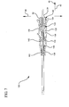
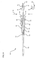
Figure 1 is an exploded perspective view of a catheter device and assembly. -
Figure 2 is a perspective view of a catheter device and assembly system undergoing a method of assembly in accordance with a representative embodiment of the present invention. -
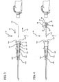
Figure 3 is a cross-sectioned view of a catheter device and assembly system undergoing a method of assembly following the step of advancing the septum actuator through the septum in accordance with a representative embodiment of the present invention. -
Figure 4 is a cross-sectioned view of a catheter device and assembly system undergoing a method of assembly prior to the step of advancing the introducer needle through the septum via the septum actuator in accordance with a representative embodiment of the present invention. -
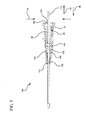
Figure 5 is a cross-sectioned view of a catheter device and assembly system undergoing a method of assembly following the step of advancing the introducer needle through the septum via the septum actuator in accordance with a representative embodiment of the present invention. -
Figure 6 is a cross-sectioned view of a catheter device and assembly system undergoing a method of assembly prior to the step of withdrawing the septum actuator from the septum in accordance with a representative embodiment the present invention. -
Figure 7 is a cross-sectioned view of a catheter device and assembly system undergoing a method of assembly following the step of withdrawing the septum actuator from the septum in accordance with a representative embodiment of the present invention. -
Figure 8 is a cross-sectioned view of a catheter device and assembly system undergoing a method of assembly prior to the step of advancing the introducer needle into the catheter in accordance with a representative embodiment of the present invention. -
Figure 9 is a cross-sectioned view of a catheter device and assembly system undergoing a method of assembly following the step of advancing the introducer needle into the catheter in accordance with a representative embodiment of the present invention. -
Figure 10 is a cross-sectioned view of a catheter device and assembly system undergoing a method of assembly following the step of coupling the needle hub with the catheter hub to provide an assembled catheter device in accordance with a representative embodiment of the present invention. -
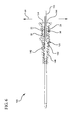
Figure 11 is a perspective view of a catheter device and assembly system prior to undergoing a method of assembly in accordance with a representative embodiment of the present invention. -
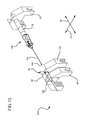
Figure 12 is a perspective view of a catheter device and assembly system following insertion of the septum actuator into the catheter adapter as part of a method of assembly in accordance with a representative embodiment of the present invention. -
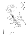
Figure 13 is a perspective view of a catheter device and assembly system following partial insertion of the introducer needle into the catheter adapter as part of a method of assembly in accordance with a representative embodiment of the present invention. -
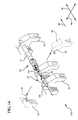
Figure 14 is a perspective view of a catheter device and assembly system demonstrating removal of the septum actuator manipulator as part of a method of assembly in accordance with a representative embodiment of the present invention. -
Figure 15 is a perspective view of a catheter device and assembly system following full insertion of the introducer needle in the catheter adapter as part of a method of assembly in accordance with a representative embodiment of the present invention. - The presently preferred embodiment of the present invention will be best understood by reference to the drawings, wherein like reference numbers indicate identical or functionally similar elements. It will be readily understood that the components of the present invention, as generally described and illustrated in the figures herein, could be arranged and designed in a wide variety of different configurations. Thus, the following more detailed description, as represented in the figures, is not intended to limit the scope of the invention as claimed, but is merely representative of presently preferred embodiments of the invention.
- Referring now to
Figure 1 , a catheterdevice assembly system 10 is shown. In some examples,system 10 comprises aclamp 20 having a first opposingarm 22 and a secondopposing arm 24. Opposingarms post 30 having afirst half 32 associated with thefirst arm 22 and asecond half 34 associated with thesecond arm 24. - In some examples, post 30 further comprises a groove or
inner surface 38 for receiving and grasping the outer surface of anintroducer needle 110 ofcatheter device 100.Post 30 further comprises a firstouter surface 36 having an outer diameter for insertedly receivingseptum actuator 120. In some examples,outer surface 36 is outwardly tapered in aproximal direction 48 so as to accommodate coupling betweenpost 30 andseptum actuator 120. In some examples, post 30 further comprises a secondouter surface 40 having an outer diameter that is greater than the diameter of firstouter surface 36, but slightly less than aninner diameter 80 ofcatheter adapter 130. As such, secondouter surface 40 acts as a guide tocoaxially center post 30 withincatheter adapter 130 during assembly. Further, any component coupled to, or gripped bypost 30 is likewise coaxially centered withincatheter adapter 130 upon insertion therein. - In some examples, clamp 20 is mechanically connected to an automation system of actuators and gears (not shown) whereby
clamp 20 is selectively repositioned along anx-axis 42 and a y-axis 44. In some embodiments, the automation system further comprises a computer and computer readable software whereby to provide an assembly program for thecatheter device 100. Movement along thex-axis 42 and y-axis 44 is provided to enableclamp 20 to grasp and position the various catheter components within thecatheter adapter 130 during assembly ofcatheter device 100. - For example, in some steps of the assembly
method opposing arms figure 2 .Septum actuator 120 is then positioned overouter surface 36 ofpost 30 preparatory to being inserted withincatheter adapter 130.Septum actuator 120 is inserted withincatheter adapter 130 asclamp 20 is moved alongx-axis 42 in adistal direction 46, as shown inFigure 3 . - In some embodiments, the position of
catheter adapter 130 is held constant by securingadapter 130 in a vise or other clamp-like device (not shown). In other embodiments,catheter adapter 130 is held in a vise or other clamp-like device capable of movement alongx-axis 42. Further, in some embodiments clamp 20 is limited to movement along y-axis 44, andcatheter adapter 130 is limited to movement alongx-axis 42. Thus, in some embodiments the method of assembly is accomplished by coordinating the movements ofclamp 20 andcatheter adapter 130 relative to one another. - In some embodiments,
catheter adapter 130 comprises a catheter hub 132 having alumen 134 for housing aseptum 140.Septum 140 is generally provided to divide lumen 134 into aforward chamber 142 and arearward chamber 144. In some embodiments,septum 140 is a split septum having a slit. The slit is provided as a pathway throughseptum 140 thereby enabling fluid communication between the forward andrearward chambers septum 140 is substantially closed prior to being biased open byseptum actuator 120. Thus, prior to being biased open,septum 140 prevents and/or controls fluid flow between forward andrearward chambers septum 140 further permits passage ofintroducer needle 110 without requiringneedle 110 to permanently pierceseptum 140. - In some embodiments,
septum actuator 120 is preliminarily positioned withinlumen 134 bypost 30 such thatactuator 120 biases the slit ofseptum 140 to an opened position, as shown inFigures 3-6 .Septum actuator 120 is advanced throughseptum 140 by repositioningclamp 20 alongx-axis 42. - In particular, in some
embodiments opposing arms axis 44 to an opened position, whereinouter surface 36 ofpost 30 contacts an inner surface ofseptum actuator 120 thereby securingactuator 120 to clamp 20.Clamp 20 is then repositioned in adistal direction 46 thereby causingseptum actuator 120 to be advanced throughseptum 140. Once positioned, opposingarms axis 44 thereby causingouter surface 36 to release the inner surface ofseptum actuator 120, as shown inFigure 3 .Clamp 20 is then repositioned alongx-axis 42 such thatpost 30 is withdrawn fromlumen 134 and positioned overintroducer needle 110, as shown inFigure 4 . Opposingarms needle 110 is gripped and secured withingroove 38 ofpost 30.Clamp 20 is then repositioned alongx-axis 42 in adistal direction 46, as shown inFigure 5 . - Referring now to
Figure 5 , clamp 20 is advanced in adistal direction 46 such that abeveled portion 112 ofneedle 110 is advance throughseptum 140 and into theforward chamber 142 viaseptum actuator 120. In some embodiments,needle 110 is advanced throughseptum actuator 120 such thatbeveled portion 112 is positioned within thewedge 146. The advanced position ofseptum actuator 120 provides a means wherebyneedle 110 is able to be inserted throughseptum 140 without damaging or otherwise compromisingseptum 140. Opposingarms outer surface 36 ofpost 30 and the inner surface ofseptum actuator 120, as shown inFigure 6 .Clamp 20 is then repositioned along thex-axis 42 in aproximal direction 48 such thatseptum actuator 120 is withdrawn from the slit ofseptum 140, as shown inFigure 7 . In some embodiments,catheter adapter 130 further comprises an annular groove orchannel 138 that receives a fin oroutward protrusion 122 ofseptum actuator 120. As such, the movement ofactuator 120 withinlumen 134 is limited to a desired range. Thus, in some embodiments clamp 20 is repositioned withinchannel 138 in aproximal direction 48 such thatseptum actuator 120 is withdrawn fromseptum 140. - Following withdrawal of
septum actuator 120 fromseptum 140, opposingarms axis 44 to a middle or neutral position, whereinpost 30 is free from contacting eitherneedle 110 orseptum actuator 120.Clamp 20 is then further repositioned along thex-axis 42 in aproximal direction 48 such thatpost 30 is withdrawn fromlumen 134, as shown inFigure 8 . - With continued reference to
Figure 8 , in some embodiments clamp 20 is further withdrawn from the proximity ofcatheter device 100, andneedle 110 is advanced in adistal direction 46 throughcatheter 136. In other embodiments, clamp 20 is repositioned along thex-axis 42 in aproximal direction 48 and clamp onto an upstream portion ofneedle 110.Clamp 20 is then repositioned along thex-axis 42 in adistal direction 46 thereby further advancingneedle 110 throughcatheter 136, as shown inFigure 9 . In some embodiments, the step of usingclamp 20 to advanceneedle 110 throughcatheter 136 is repeated untilbeveled portion 112 is advanced to a desired position withcatheter 136. In other embodiments, clamp 20 further withdrawn from the proximity ofcatheter device 100, andneedle 110 is advanced in adistal direction 46 throughcatheter 136 until thecatheter device 100 is fully assembled, as shown inFigure 10 . - In some methods of the present invention, a
catheter device 100 is assembled by first providing acatheter adapter 130 having aproximal opening 150, adistal opening 152, and alumen 134 extending therebetween. Acatheter 136 is then swaged into thedistal opening 142 of the catheter adapter, such that a lumen of thecatheter 136 andlumen 134 are in fluid communication. Aseptum 140 is then insertedly positioned withinlumen 134 thereby dividinglumen 134 into aforward chamber 142 and arearward chamber 144. - The
catheter device 100 is further assembled by insertedly positioning aseptum actuator 120 through theseptum 140 according to the method outlined above. For example, in some methods aclamp 20 is used to access and insertedly position theseptum actuator 120 within theseptum 140. Theclamp 20 generally comprises an opened position, a closed position, and a middle position whereby theclamp 20 is capable of gripping theseptum actuator 120 and anintroducer needle 110 of thecatheter device 100. - In some methods,
clamp 20 is first used to grip andadvance septum actuator 120 throughseptum 140.Clamp 20 then releasesseptum actuator 120 and grips introducerneedle 110.Clamp 20 then advancesneedle 110 intolumen 134 such that abeveled tip 112 ofneedle 110 bypassesseptum 140 viaseptum actuator 120 and into theforward chamber 142. In some methods, a step of adding a lubricant to thetip 112 ofneedle 110 is performed prior to advancingneedle 110 intolumen 134. Thus, in some methods clamp 20 grips needle 110 at position proximate to a lubricated tip portion ofneedle 110. - Following insertion of
needle tip 112, clamp 20 is then moved to the opened position wherebyclamp 20 releases needle 110 and secures the inner surface ofseptum actuator 120.Clamp 20 is then withdrawn in aproximal direction 48 thereby removingseptum actuator 120 fromseptum 140, such thatseptum actuator 120 is entirely positioned within therearward chamber 144.Clamp 20 is then moved to the middle position such that theclamp 20 is free from contacting either theseptum actuator 120 or theneedle 110. While in the middle position, clamp 20 is withdrawn fromlumen 134 and removed entirely from thecatheter device 100. Theneedle 110 is then completely advanced withincatheter 136 thereby completing the assembly of thecatheter device 100. - In some methods, the step of withdrawing
clamp 20 fromlumen 134 further comprises the step of repositioningclamp 20 to the closed position so as to grip a proximal portion ofneedle 110.Clamp 20 is then repositioned in adistal direction 46 whereby thebeveled tip 112 ofneedle 110 is further advanced through theforward chamber 142 and intocatheter 136.Clamp 20 is then moved to the middle position and withdrawn fromlumen 134. - Referring now to
Figure 11 , in someembodiments assembly system 210 further comprises astationary clamp 60.Stationary clamp 60 is provided as means whereby to grip and holdneedle adapter 12 during the assembly process. In some embodiments,stationary clamp 60 is mechanically connected to an automation system of actuators and gears (not shown) wherebyclamp 60 is selectively repositioned alongaxis 42 andaxis 44. -
Assembly system 210 further includes acatheter adapter manipulator 64 and aseptum actuator manipulator 20, or clamp, as previously discussed.Manipulator 64 is provided as means whereby to grip and holdcatheter adapter 130 during the assembly process.Manipulator 64 is mechanically connected to an automation system of actuators and gears (not shown) wherebymanipulator 64 is selectively repositioned alongaxis 42 andaxis 44. In some embodiments,manipulator 64 is fixedly positioned such thatcatheter adapter 130 is maintained in a stationary position throughout the assembly process. For example, in someassembly processes manipulator 64 maintains a stationary position ofcatheter adapter 130 whileclamp 20 and clamp 60 are selectively repositioned alongaxis 42 andaxis 44 to assemble the various components ofcatheter device 100. - Referring now to
Figure 12 , anassembly system 210 is shown whereinclamp 60 is a stationary clamp, and clamps 20 and 64 are selectively repositioned alongaxis 42. A first step ofassembly system 210 is to insertseptum actuator 120 intocatheter adapter 130. This first step is accomplished by selectively repositioning at least one ofclamp 20 and clamp 64 such thatseptum actuator 120 is inserted intocatheter adapter 130.Septum actuator 120 is held byclamp 20 by positioning first andsecond halves Septum actuator 120 is inserted withincatheter adapter 130 untilseptum actuator 120 is advance throughseptum 140, thereby providing a pathway throughseptum 140. - A second step of
assembly system 210 is to partially insertneedle 110 throughseptum actuator 120 and intowedge 146 ofcatheter adapter 130, as shown inFigure 13 . Having positioned theseptum actuator 120 throughseptum 140,needle 110 may now safely bypassseptum 140 without puncturing or otherwisedamaging septum 140. - Once
needle 110 is positioned withincatheter adapter 130, clamp 20 is moved in aproximal direction 48 to removeseptum actuator 120 fromseptum 140, andposition septum actuator 120 just proximal toseptum 140.Clamp 20 is then moved to a closed position and repositioned in aproximal direction 48, as shown inFigure 14 . In some embodiments, groove 38 ofclamp 20 comprises a diameter greater than the outer diameter ofintroducer needle 110. This feature allows clamp 20 to be repositioned relative toneedle 110 while in the closed position. Oncepost 30 has clearedcatheter adapter 130, clamp 20 is removed fromneedle 110, as shown.Clamp 64 is then repositioned in aproximal direction 48 thereby fully advancingneedle 110 throughcatheter adapter 130 andcatheter 136, such thatneedle 110 extends distally beyondcatheter 136, as shown inFigure 15 . The final step is to removeclamp 64 andstationary clamp 60 from assembledcatheter device 100. - The present invention may be embodied in other specific forms without departing from its structures, methods, or other essential characteristics as broadly described herein and claimed hereinafter. The described embodiments are to be considered in all respects only as illustrative, and not restrictive.
Claims (8)
- A method for manufacturing a catheter assembly (100), the method comprising:providing a catheter adapter (130) having a proximal opening (150), a distal opening (152), and a lumen (134) therebetween;swaging a catheter (136) into the distal opening (152) of the catheter adapter (130), the catheter (136) and the lumen (134) being in fluid communication;insertedly positioning a septum (140) into the lumen (134), whereby the septum (140) divides the lumen (134) into a forward chamber (142) and a rearward chamber (144);inserting a septum actuator (120) into the catheter adapter (130);advancing the septum actuator (120) through the septum (140) thereby providing a pathway between the forward chamber (142) and the rearward chamber (144), the septum actuator (120) being approximately coaxially centered within the catheter adapter (130); characterised in that the method further comprisesproviding a clamp (20) having a closed position, an opened position, and a middle position, the clamp (20) further having an inner surface (38) for gripping a needle (110), and an outer surface (36) for selectively contacting an inner surface of the septum actuator (120);gripping the needle (110) with the inner surface (38) of the clamp (20) by positioning the clamp (20) to the closed position;advancing the needle (110) and clamp (20) into the proximal opening (150) of the catheter adapter (130) in a distal direction such that the clamp (20) and needle (110) are approximately coaxially centered within the septum actuator (120), and such that a tip portion (112) of the needle (110) is positioned in the forward chamber (142);repositioning the clamp (20) to the opened position such that the inner surface (38) of the clamp (20) releases the needle (110), and the outer surface (36) of the clamp (20) contacts the inner surface (38) of the septum actuator (120);withdrawing the clamp (20) and septum actuator (120) in a proximal direction such that the septum actuator (120) is withdrawn from the septum (140) and is entirely positioned in the rearward chamber (144);repositioning the clamp (20) to the middle position such that neither the inner surface (38) nor the outer surface (36) of the clamp (20) contact the needle (110) nor the septum actuator (120), respectively;withdrawing the clamp (20) from the rearward chamber (144); andremoving the clamp (20) from the catheter assembly (100).
- The method of claim 1, wherein following the step of withdrawing the clamp (20) from the rearward chamber (144), the method further includes the steps of:repositioning the clamp (20) to the closed position so as the grip a proximal portion of the needle (110);advancing the clamp (20) and the needle (110) in the distal direction whereby the tip portion (112) of the needle (110) is advanced through the forward chamber (142) and into the catheter (136);repositioning the clamp (20) to the middle position; andwithdrawing the clamp (20) in the proximal direction such that the clamp (20) is removed from the rearward chamber (144).
- The method of claim 1, further comprising coating the tip portion (112) of the needle (110) with a lubricant.
- The method of claim 3, further comprising gripping the needle (110) at a position proximate to the lubricant.
- The method of claim 1, wherein an outer diameter of the clamp (20) coaxially centers the needle (110) and the clamp (20) within the septum actuator (120).
- The method of claim 1, wherein the outer surface (36) of the clamp (20) is outwardly tapered in the proximal direction.
- The method of claim 5, wherein the outer diameter is less than an inner diameter of the catheter adapter (130) and greater than an inner diameter of the septum actuator (120).
- The method of claim 1, further comprising coupling the clamp (20) to an automation system, wherein the automation system controls the positions of the clamp (20) relative to the needle (110) and the catheter assembly (100).
Applications Claiming Priority (2)
| Application Number | Priority Date | Filing Date | Title |
|---|---|---|---|
| US12/877,494 US8864715B2 (en) | 2010-09-08 | 2010-09-08 | Assembly method for catheter with blood control |
| PCT/US2011/048281 WO2012033624A1 (en) | 2010-09-08 | 2011-08-18 | Assembly method for catheter with blood control |
Publications (2)
| Publication Number | Publication Date |
|---|---|
| EP2613841A1 EP2613841A1 (en) | 2013-07-17 |
| EP2613841B1 true EP2613841B1 (en) | 2014-12-31 |
Family
ID=44513206
Family Applications (1)
| Application Number | Title | Priority Date | Filing Date |
|---|---|---|---|
| EP11749061.5A Active EP2613841B1 (en) | 2010-09-08 | 2011-08-18 | Assembly method for catheter with blood control |
Country Status (8)
| Country | Link |
|---|---|
| US (2) | US8864715B2 (en) |
| EP (1) | EP2613841B1 (en) |
| JP (1) | JP6057899B2 (en) |
| CN (1) | CN103189093B (en) |
| AU (1) | AU2011299466B2 (en) |
| CA (1) | CA2810684C (en) |
| ES (1) | ES2533592T3 (en) |
| WO (1) | WO2012033624A1 (en) |
Families Citing this family (17)
| Publication number | Priority date | Publication date | Assignee | Title |
|---|---|---|---|---|
| JP4994775B2 (en) * | 2006-10-12 | 2012-08-08 | 日本コヴィディエン株式会社 | Needle point protector |
| US8486024B2 (en) | 2011-04-27 | 2013-07-16 | Covidien Lp | Safety IV catheter assemblies |
| EP2760520A1 (en) | 2011-09-26 | 2014-08-06 | Covidien LP | Safety catheter |
| WO2013048768A1 (en) | 2011-09-26 | 2013-04-04 | Covidien Lp | Safety iv catheter and needle assembly |
| US9358364B2 (en) * | 2011-10-06 | 2016-06-07 | Becton, Dickinson And Company | Activator attachment for blood control catheters |
| US8834422B2 (en) | 2011-10-14 | 2014-09-16 | Covidien Lp | Vascular access assembly and safety device |
| US9592367B2 (en) * | 2013-07-30 | 2017-03-14 | Becton, Dickinson And Company | Blood control catheter valve employing actuator with flexible retention arms |
| SG10202007098SA (en) | 2014-04-18 | 2020-08-28 | Becton Dickinson Co | Needle capture safety interlock for catheter |
| MX2017013349A (en) | 2015-04-17 | 2018-03-01 | Becton Dickinson Co | Multi-Use Blood Control Safety Catheter Assembly. |
| DK3552652T3 (en) | 2015-08-18 | 2021-07-12 | Braun Melsungen Ag | CATHETER FACILITIES WITH VALVES |
| CN105149925B (en) * | 2015-09-30 | 2017-05-24 | 迈得医疗工业设备股份有限公司 | Device for assembling needle tubing and rubber plug |
| CN105128327B (en) * | 2015-09-30 | 2017-03-22 | 迈得医疗工业设备股份有限公司 | Rubber plug and needle tube assembling device |
| US11826522B2 (en) * | 2016-06-01 | 2023-11-28 | Becton, Dickinson And Company | Medical devices, systems and methods utilizing permanent magnet and magnetizable feature |
| CN106181287B (en) * | 2016-08-24 | 2019-05-24 | 迈得医疗工业设备股份有限公司 | Metal needle component assembling device |
| WO2020127328A1 (en) | 2018-12-17 | 2020-06-25 | B. Braun Melsungen Ag | Over-the-needle catheter assemblies and related manufacturing method |
| CN110303314B (en) * | 2018-12-24 | 2023-08-08 | 江天云 | Butterfly wing assembly machine |
| CA3216103A1 (en) * | 2021-04-13 | 2022-10-20 | Bard Access Systems, Inc. | Access systems, devices, and methods thereof |
Family Cites Families (72)
| Publication number | Priority date | Publication date | Assignee | Title |
|---|---|---|---|---|
| DE2817102C2 (en) | 1978-04-19 | 1985-01-24 | Dr. Eduard Fresenius, Chemisch-pharmazeutische Industrie KG, 6380 Bad Homburg | Connector for plastic cannulas or venous catheters |
| US4449693A (en) | 1982-09-30 | 1984-05-22 | Gereg Gordon A | Catheter check valve |
| GB8527646D0 (en) | 1985-11-08 | 1985-12-11 | Cox J A | Devices for sampling drainage |
| GB8627808D0 (en) | 1986-11-20 | 1986-12-17 | Cox J A | Sampling liquids from human/animal body |
| US4842591A (en) | 1988-01-21 | 1989-06-27 | Luther Ronald B | Connector with one-way septum valve, and assembly |
| DE3809127C1 (en) | 1988-03-18 | 1989-04-13 | B. Braun Melsungen Ag, 3508 Melsungen, De | |
| US4874377A (en) | 1988-05-26 | 1989-10-17 | Davis Newgard Revocable Family Living Trust | Self-occluding intravascular cannula assembly |
| US5064416A (en) | 1988-05-26 | 1991-11-12 | Newgard Kent W | Self-occluding intravascular cannula assembly |
| US5053014A (en) | 1990-02-01 | 1991-10-01 | Critikon, Inc. | Catheter with controlled valve |
| US5041097A (en) | 1990-02-26 | 1991-08-20 | Johnson Gerald W | Intravenous catheter fitting with protective end seal |
| US5062836A (en) | 1990-03-14 | 1991-11-05 | The Kendall Company | Placement device for a catheter and guide wire |
| US5084023A (en) | 1990-03-22 | 1992-01-28 | Critikon, Inc. | Bloodless catheter with self-shielding needle |
| US5108374A (en) | 1990-05-02 | 1992-04-28 | Critikon, Inc. | Stickless catheter with manual shut-off valve |
| US5127905A (en) | 1990-05-02 | 1992-07-07 | Critikon, Inc. | Stickless catheter with manual shut-off valve |
| US5085645A (en) | 1990-08-15 | 1992-02-04 | Becton, Dickinson And Company | Apparatus and method for a catheter adapter with valve |
| US5154703A (en) | 1990-10-30 | 1992-10-13 | Care Medical Devices, Inc. | Bloodless catheter |
| US5156596A (en) | 1991-02-04 | 1992-10-20 | Menlo Care, Inc. | Catheter with changeable number of lumens |
| US5295969A (en) | 1992-04-27 | 1994-03-22 | Cathco, Inc. | Vascular access device with air-tight blood containment capability |
| US5234410A (en) | 1992-10-23 | 1993-08-10 | Vlv Associates | Catheter assembly |
| US5330435A (en) | 1993-04-08 | 1994-07-19 | Vaillancourt Vincent L | Valve for a catheter assembly |
| DE4311715C2 (en) | 1993-04-08 | 1996-02-01 | Fresenius Ag | Port cannula |
| US5350363A (en) | 1993-06-14 | 1994-09-27 | Cordis Corporation | Enhanced sheath valve |
| US5657963A (en) | 1993-06-16 | 1997-08-19 | United States Surgical Corporation | Seal assembly for accommodating introduction of surgical instruments |
| US5352205A (en) | 1993-09-16 | 1994-10-04 | Lawrence Dales | Bloodless insertion catheter assembly |
| JP2584597B2 (en) | 1993-09-29 | 1997-02-26 | ベクトン・ディッキンソン・アンド・カンパニー | Catheter introduction device with blood seal |
| US5806831A (en) | 1993-10-13 | 1998-09-15 | Paradis; Joseph R. | Control of fluid flow with internal cannula |
| US5549577A (en) | 1993-12-29 | 1996-08-27 | Ivac Corporation | Needleless connector |
| US5522804A (en) | 1994-02-15 | 1996-06-04 | Lynn; Lawrence A. | Aspiration, mixing, and injection syringe |
| US5405323A (en) | 1994-02-22 | 1995-04-11 | Aeroquip Corporation | Catheter check valve assembly |
| US5487728A (en) | 1994-05-19 | 1996-01-30 | Vaillancourt; Vincent L. | Connector assembly |
| US5549566A (en) | 1994-10-27 | 1996-08-27 | Abbott Laboratories | Valved intravenous fluid line infusion device |
| DE4442352C1 (en) | 1994-11-29 | 1995-12-21 | Braun Melsungen Ag | Valve arrangement provided in connector for use e.g. with cannula |
| US5520666A (en) | 1994-12-06 | 1996-05-28 | Abbott Laboratories | Valved intravenous fluid line connector |
| US5575769A (en) * | 1995-05-30 | 1996-11-19 | Vaillancourt; Vincent L. | Cannula for a slit septum and a lock arrangement therefore |
| IT1285266B1 (en) | 1996-02-26 | 1998-06-03 | Borla Ind | CONNECTOR WITH PROTECTION VALVE FOR INFUSION / TRANSFUSION AND SIMILAR MEDICAL LINES. |
| US5817069A (en) | 1996-02-28 | 1998-10-06 | Vadus, Inc. | Valve assembly |
| US5651772A (en) | 1996-02-28 | 1997-07-29 | Aeroquip Corporation | Needle guard assembly |
| US6273869B1 (en) | 1996-06-13 | 2001-08-14 | Vincent L. Vaillancourt | Valve connector |
| US5738144A (en) | 1996-10-11 | 1998-04-14 | Aeroquip Corporation | Luer connecting coupling |
| EP0952868B1 (en) | 1996-11-18 | 2004-03-31 | Nypro, Inc. | Swabbable luer-coned valve |
| US6883778B1 (en) | 1996-11-18 | 2005-04-26 | Nypro Inc. | Apparatus for reducing fluid drawback through a medical valve |
| US5951520A (en) * | 1996-12-19 | 1999-09-14 | Bio-Plexus, Inc. | Self-blunting needle medical devices and methods of manufacture thereof |
| US5954698A (en) | 1997-01-08 | 1999-09-21 | Vadus, Inc. | Catheter apparatus having valved catheter hub and needle protector |
| US5967490A (en) | 1997-01-08 | 1999-10-19 | Vadus, Inc. | Catheter hubs having a valve |
| US5911710A (en) | 1997-05-02 | 1999-06-15 | Schneider/Namic | Medical insertion device with hemostatic valve |
| US6117108A (en) | 1997-08-20 | 2000-09-12 | Braun Melsungen Ag | Spring clip safety IV catheter |
| US6077244A (en) | 1998-04-30 | 2000-06-20 | Mdc Investment Holdings, Inc. | Catheter insertion device with retractable needle |
| NL1007997C2 (en) | 1998-01-09 | 1999-07-12 | Cordis Europ | Device for inserting an elongated medical device. |
| US6652490B2 (en) | 1998-04-09 | 2003-11-25 | Becton Dickinson And Company | Catheter and introducer needle assembly with compact needle shield |
| MXPA00011767A (en) | 1998-05-29 | 2002-10-17 | Lawrence A Lynn | Luer receiver and method for fluid transfer. |
| US6213978B1 (en) * | 1998-10-27 | 2001-04-10 | Cherie A. Voyten | Intravenous catheter insertion apparatus |
| US6331176B1 (en) | 1999-03-11 | 2001-12-18 | Advanced Cardiovascular Systems, Inc. | Bleed back control assembly and method |
| CA2380907C (en) | 1999-08-12 | 2009-12-08 | Lawrence A. Lynn | Luer receiving vascular access system |
| FR2802432B1 (en) | 1999-12-16 | 2002-03-08 | Vygon | AUTOMATIC SHUTTER CONNECTOR FOR CONNECTING A LIQUID INJECTION HEAD TO AN INJECTION OUTPUT |
| US6699221B2 (en) | 2000-06-15 | 2004-03-02 | Vincent L. Vaillancourt | Bloodless catheter |
| JP4996015B2 (en) * | 2001-03-12 | 2012-08-08 | メディキット株式会社 | Indwelling catheter |
| JP2003230631A (en) * | 2002-02-07 | 2003-08-19 | Terumo Corp | Insertion auxiliary fitting and catheter equipped with the insertion auxiliary fitting |
| JP3808806B2 (en) | 2002-06-26 | 2006-08-16 | メディキット株式会社 | Indwelling needle |
| DE20210394U1 (en) * | 2002-07-04 | 2002-09-12 | Braun Melsungen Ag | catheter introducer |
| EP1388769A1 (en) * | 2002-08-05 | 2004-02-11 | Peter Renner | System for automation, surveillance, control, detection of measured values for technical processes |
| US7347839B2 (en) * | 2003-02-12 | 2008-03-25 | Nipro Corporation | Indwelling catheter |
| US7332227B2 (en) * | 2003-03-14 | 2008-02-19 | Becton, Dickinson And Company | Non-volatile lubricant system for medical devices |
| EP3381495B1 (en) * | 2003-03-25 | 2020-07-15 | Becton, Dickinson and Company | Iv catheter and needle assembly and method |
| US7126303B2 (en) | 2003-07-08 | 2006-10-24 | Board Of Regents Of The University Of Nebraska | Robot for surgical applications |
| US7470254B2 (en) | 2003-08-18 | 2008-12-30 | Medical Components, Inc. | Needle with sealing valve |
| US20060085004A1 (en) | 2004-07-13 | 2006-04-20 | I Chu Spring Co., Ltd. | Injection drill assembly |
| US20070083162A1 (en) | 2005-10-11 | 2007-04-12 | Span-America Medical Systems, Inc. | Valve for intravenous catheter |
| US8308691B2 (en) | 2006-11-03 | 2012-11-13 | B. Braun Melsungen Ag | Catheter assembly and components thereof |
| JP2008043445A (en) | 2006-08-11 | 2008-02-28 | Medikit Kk | Catheter, hollow needle and dwelling needle assembly |
| CN101210849B (en) * | 2006-12-28 | 2011-05-25 | 上海康德莱企业发展集团股份有限公司 | 0.4mmQuick-speed jigs for needle tube under 0.4mm and method of use thereof |
| WO2008152849A1 (en) * | 2007-06-12 | 2008-12-18 | Terumo Kabushiki Kaisha | Method of producing indwelling needle assembly and indwelling needle assembly |
| US8469928B2 (en) * | 2009-02-11 | 2013-06-25 | Becton, Dickinson And Company | Systems and methods for providing a flushable catheter assembly |
-
2010
- 2010-09-08 US US12/877,494 patent/US8864715B2/en active Active
-
2011
- 2011-08-18 CN CN201180051424.5A patent/CN103189093B/en active Active
- 2011-08-18 WO PCT/US2011/048281 patent/WO2012033624A1/en active Application Filing
- 2011-08-18 EP EP11749061.5A patent/EP2613841B1/en active Active
- 2011-08-18 CA CA2810684A patent/CA2810684C/en active Active
- 2011-08-18 JP JP2013528213A patent/JP6057899B2/en active Active
- 2011-08-18 AU AU2011299466A patent/AU2011299466B2/en active Active
- 2011-08-18 ES ES11749061.5T patent/ES2533592T3/en active Active
-
2012
- 2012-03-27 US US13/431,781 patent/US8636695B2/en active Active
Also Published As
| Publication number | Publication date |
|---|---|
| WO2012033624A1 (en) | 2012-03-15 |
| CN103189093A (en) | 2013-07-03 |
| AU2011299466A1 (en) | 2013-04-11 |
| CN103189093B (en) | 2015-04-15 |
| US20120184912A1 (en) | 2012-07-19 |
| CA2810684C (en) | 2018-03-06 |
| JP6057899B2 (en) | 2017-01-11 |
| US8636695B2 (en) | 2014-01-28 |
| AU2011299466B2 (en) | 2014-08-07 |
| JP2013539400A (en) | 2013-10-24 |
| CA2810684A1 (en) | 2012-03-15 |
| US8864715B2 (en) | 2014-10-21 |
| EP2613841A1 (en) | 2013-07-17 |
| ES2533592T3 (en) | 2015-04-13 |
| US20120059325A1 (en) | 2012-03-08 |
Similar Documents
| Publication | Publication Date | Title |
|---|---|---|
| EP2613841B1 (en) | Assembly method for catheter with blood control | |
| US10478609B2 (en) | Blood control catheter valve employing actuator with flexible retention arms | |
| AU2020281009B2 (en) | Compliant catheter adapter having self-slitting needle | |
| EP3744382B1 (en) | Integrated catheter with independent fluid paths | |
| CN101612435B (en) | Vascular access device | |
| EP2231252B1 (en) | Catheter assembly and method of manufacturing the same | |
| CA2585475A1 (en) | Universal catheter tunneler | |
| EP2015828A2 (en) | Luer connector assembly with clamping sleeve and method of use | |
| EP0603325B1 (en) | Puncture needle device, mainly for a closed system introduction of a catheter into a blood vessel | |
| US20230226323A1 (en) | Intravenous cannula | |
| US20050228458A1 (en) | Finishing wire assembly having variable insertion length and method therefor | |
| WO2024015551A1 (en) | Blood draw connector for vascular access system | |
| CN114247030A (en) | Changeable catheter sheath |
Legal Events
| Date | Code | Title | Description |
|---|---|---|---|
| PUAI | Public reference made under article 153(3) epc to a published international application that has entered the european phase |
Free format text: ORIGINAL CODE: 0009012 |
|
| 17P | Request for examination filed |
Effective date: 20130320 |
|
| AK | Designated contracting states |
Kind code of ref document: A1 Designated state(s): AL AT BE BG CH CY CZ DE DK EE ES FI FR GB GR HR HU IE IS IT LI LT LU LV MC MK MT NL NO PL PT RO RS SE SI SK SM TR |
|
| DAX | Request for extension of the european patent (deleted) | ||
| 17Q | First examination report despatched |
Effective date: 20140207 |
|
| GRAP | Despatch of communication of intention to grant a patent |
Free format text: ORIGINAL CODE: EPIDOSNIGR1 |
|
| INTG | Intention to grant announced |
Effective date: 20140721 |
|
| GRAS | Grant fee paid |
Free format text: ORIGINAL CODE: EPIDOSNIGR3 |
|
| GRAA | (expected) grant |
Free format text: ORIGINAL CODE: 0009210 |
|
| AK | Designated contracting states |
Kind code of ref document: B1 Designated state(s): AL AT BE BG CH CY CZ DE DK EE ES FI FR GB GR HR HU IE IS IT LI LT LU LV MC MK MT NL NO PL PT RO RS SE SI SK SM TR |
|
| REG | Reference to a national code |
Ref country code: CH Ref legal event code: EP Ref country code: GB Ref legal event code: FG4D |
|
| REG | Reference to a national code |
Ref country code: IE Ref legal event code: FG4D |
|
| REG | Reference to a national code |
Ref country code: AT Ref legal event code: REF Ref document number: 704011 Country of ref document: AT Kind code of ref document: T Effective date: 20150215 |
|
| REG | Reference to a national code |
Ref country code: DE Ref legal event code: R096 Ref document number: 602011012743 Country of ref document: DE Effective date: 20150219 |
|
| REG | Reference to a national code |
Ref country code: ES Ref legal event code: FG2A Ref document number: 2533592 Country of ref document: ES Kind code of ref document: T3 Effective date: 20150413 |
|
| REG | Reference to a national code |
Ref country code: SE Ref legal event code: TRGR |
|
| PG25 | Lapsed in a contracting state [announced via postgrant information from national office to epo] |
Ref country code: FI Free format text: LAPSE BECAUSE OF FAILURE TO SUBMIT A TRANSLATION OF THE DESCRIPTION OR TO PAY THE FEE WITHIN THE PRESCRIBED TIME-LIMIT Effective date: 20141231 Ref country code: NO Free format text: LAPSE BECAUSE OF FAILURE TO SUBMIT A TRANSLATION OF THE DESCRIPTION OR TO PAY THE FEE WITHIN THE PRESCRIBED TIME-LIMIT Effective date: 20150331 Ref country code: LT Free format text: LAPSE BECAUSE OF FAILURE TO SUBMIT A TRANSLATION OF THE DESCRIPTION OR TO PAY THE FEE WITHIN THE PRESCRIBED TIME-LIMIT Effective date: 20141231 |
|
| REG | Reference to a national code |
Ref country code: NL Ref legal event code: VDEP Effective date: 20141231 |
|
| REG | Reference to a national code |
Ref country code: LT Ref legal event code: MG4D |
|
| PG25 | Lapsed in a contracting state [announced via postgrant information from national office to epo] |
Ref country code: HR Free format text: LAPSE BECAUSE OF FAILURE TO SUBMIT A TRANSLATION OF THE DESCRIPTION OR TO PAY THE FEE WITHIN THE PRESCRIBED TIME-LIMIT Effective date: 20141231 Ref country code: LV Free format text: LAPSE BECAUSE OF FAILURE TO SUBMIT A TRANSLATION OF THE DESCRIPTION OR TO PAY THE FEE WITHIN THE PRESCRIBED TIME-LIMIT Effective date: 20141231 Ref country code: GR Free format text: LAPSE BECAUSE OF FAILURE TO SUBMIT A TRANSLATION OF THE DESCRIPTION OR TO PAY THE FEE WITHIN THE PRESCRIBED TIME-LIMIT Effective date: 20150401 Ref country code: RS Free format text: LAPSE BECAUSE OF FAILURE TO SUBMIT A TRANSLATION OF THE DESCRIPTION OR TO PAY THE FEE WITHIN THE PRESCRIBED TIME-LIMIT Effective date: 20141231 |
|
| REG | Reference to a national code |
Ref country code: AT Ref legal event code: MK05 Ref document number: 704011 Country of ref document: AT Kind code of ref document: T Effective date: 20141231 |
|
| PG25 | Lapsed in a contracting state [announced via postgrant information from national office to epo] |
Ref country code: NL Free format text: LAPSE BECAUSE OF FAILURE TO SUBMIT A TRANSLATION OF THE DESCRIPTION OR TO PAY THE FEE WITHIN THE PRESCRIBED TIME-LIMIT Effective date: 20141231 |
|
| PG25 | Lapsed in a contracting state [announced via postgrant information from national office to epo] |
Ref country code: RO Free format text: LAPSE BECAUSE OF FAILURE TO SUBMIT A TRANSLATION OF THE DESCRIPTION OR TO PAY THE FEE WITHIN THE PRESCRIBED TIME-LIMIT Effective date: 20141231 Ref country code: SK Free format text: LAPSE BECAUSE OF FAILURE TO SUBMIT A TRANSLATION OF THE DESCRIPTION OR TO PAY THE FEE WITHIN THE PRESCRIBED TIME-LIMIT Effective date: 20141231 Ref country code: CZ Free format text: LAPSE BECAUSE OF FAILURE TO SUBMIT A TRANSLATION OF THE DESCRIPTION OR TO PAY THE FEE WITHIN THE PRESCRIBED TIME-LIMIT Effective date: 20141231 |
|
| PG25 | Lapsed in a contracting state [announced via postgrant information from national office to epo] |
Ref country code: PL Free format text: LAPSE BECAUSE OF FAILURE TO SUBMIT A TRANSLATION OF THE DESCRIPTION OR TO PAY THE FEE WITHIN THE PRESCRIBED TIME-LIMIT Effective date: 20141231 Ref country code: IS Free format text: LAPSE BECAUSE OF FAILURE TO SUBMIT A TRANSLATION OF THE DESCRIPTION OR TO PAY THE FEE WITHIN THE PRESCRIBED TIME-LIMIT Effective date: 20150430 Ref country code: AT Free format text: LAPSE BECAUSE OF FAILURE TO SUBMIT A TRANSLATION OF THE DESCRIPTION OR TO PAY THE FEE WITHIN THE PRESCRIBED TIME-LIMIT Effective date: 20141231 |
|
| REG | Reference to a national code |
Ref country code: DE Ref legal event code: R097 Ref document number: 602011012743 Country of ref document: DE |
|
| PG25 | Lapsed in a contracting state [announced via postgrant information from national office to epo] |
Ref country code: DK Free format text: LAPSE BECAUSE OF FAILURE TO SUBMIT A TRANSLATION OF THE DESCRIPTION OR TO PAY THE FEE WITHIN THE PRESCRIBED TIME-LIMIT Effective date: 20141231 Ref country code: EE Free format text: LAPSE BECAUSE OF FAILURE TO SUBMIT A TRANSLATION OF THE DESCRIPTION OR TO PAY THE FEE WITHIN THE PRESCRIBED TIME-LIMIT Effective date: 20141231 |
|
| PLBE | No opposition filed within time limit |
Free format text: ORIGINAL CODE: 0009261 |
|
| STAA | Information on the status of an ep patent application or granted ep patent |
Free format text: STATUS: NO OPPOSITION FILED WITHIN TIME LIMIT |
|
| 26N | No opposition filed |
Effective date: 20151001 |
|
| PG25 | Lapsed in a contracting state [announced via postgrant information from national office to epo] |
Ref country code: SI Free format text: LAPSE BECAUSE OF FAILURE TO SUBMIT A TRANSLATION OF THE DESCRIPTION OR TO PAY THE FEE WITHIN THE PRESCRIBED TIME-LIMIT Effective date: 20141231 |
|
| PG25 | Lapsed in a contracting state [announced via postgrant information from national office to epo] |
Ref country code: MC Free format text: LAPSE BECAUSE OF FAILURE TO SUBMIT A TRANSLATION OF THE DESCRIPTION OR TO PAY THE FEE WITHIN THE PRESCRIBED TIME-LIMIT Effective date: 20141231 Ref country code: LU Free format text: LAPSE BECAUSE OF FAILURE TO SUBMIT A TRANSLATION OF THE DESCRIPTION OR TO PAY THE FEE WITHIN THE PRESCRIBED TIME-LIMIT Effective date: 20150818 |
|
| REG | Reference to a national code |
Ref country code: CH Ref legal event code: PL |
|
| PG25 | Lapsed in a contracting state [announced via postgrant information from national office to epo] |
Ref country code: LI Free format text: LAPSE BECAUSE OF NON-PAYMENT OF DUE FEES Effective date: 20150831 Ref country code: CH Free format text: LAPSE BECAUSE OF NON-PAYMENT OF DUE FEES Effective date: 20150831 |
|
| PG25 | Lapsed in a contracting state [announced via postgrant information from national office to epo] |
Ref country code: BE Free format text: LAPSE BECAUSE OF FAILURE TO SUBMIT A TRANSLATION OF THE DESCRIPTION OR TO PAY THE FEE WITHIN THE PRESCRIBED TIME-LIMIT Effective date: 20141231 |
|
| REG | Reference to a national code |
Ref country code: FR Ref legal event code: PLFP Year of fee payment: 6 |
|
| PG25 | Lapsed in a contracting state [announced via postgrant information from national office to epo] |
Ref country code: MT Free format text: LAPSE BECAUSE OF FAILURE TO SUBMIT A TRANSLATION OF THE DESCRIPTION OR TO PAY THE FEE WITHIN THE PRESCRIBED TIME-LIMIT Effective date: 20141231 |
|
| PG25 | Lapsed in a contracting state [announced via postgrant information from national office to epo] |
Ref country code: HU Free format text: LAPSE BECAUSE OF FAILURE TO SUBMIT A TRANSLATION OF THE DESCRIPTION OR TO PAY THE FEE WITHIN THE PRESCRIBED TIME-LIMIT; INVALID AB INITIO Effective date: 20110818 Ref country code: SM Free format text: LAPSE BECAUSE OF FAILURE TO SUBMIT A TRANSLATION OF THE DESCRIPTION OR TO PAY THE FEE WITHIN THE PRESCRIBED TIME-LIMIT Effective date: 20141231 Ref country code: BG Free format text: LAPSE BECAUSE OF FAILURE TO SUBMIT A TRANSLATION OF THE DESCRIPTION OR TO PAY THE FEE WITHIN THE PRESCRIBED TIME-LIMIT Effective date: 20141231 |
|
| PG25 | Lapsed in a contracting state [announced via postgrant information from national office to epo] |
Ref country code: CY Free format text: LAPSE BECAUSE OF FAILURE TO SUBMIT A TRANSLATION OF THE DESCRIPTION OR TO PAY THE FEE WITHIN THE PRESCRIBED TIME-LIMIT Effective date: 20141231 |
|
| REG | Reference to a national code |
Ref country code: FR Ref legal event code: PLFP Year of fee payment: 7 |
|
| PG25 | Lapsed in a contracting state [announced via postgrant information from national office to epo] |
Ref country code: MK Free format text: LAPSE BECAUSE OF FAILURE TO SUBMIT A TRANSLATION OF THE DESCRIPTION OR TO PAY THE FEE WITHIN THE PRESCRIBED TIME-LIMIT Effective date: 20141231 Ref country code: TR Free format text: LAPSE BECAUSE OF FAILURE TO SUBMIT A TRANSLATION OF THE DESCRIPTION OR TO PAY THE FEE WITHIN THE PRESCRIBED TIME-LIMIT Effective date: 20141231 |
|
| REG | Reference to a national code |
Ref country code: FR Ref legal event code: PLFP Year of fee payment: 8 |
|
| PG25 | Lapsed in a contracting state [announced via postgrant information from national office to epo] |
Ref country code: PT Free format text: LAPSE BECAUSE OF FAILURE TO SUBMIT A TRANSLATION OF THE DESCRIPTION OR TO PAY THE FEE WITHIN THE PRESCRIBED TIME-LIMIT Effective date: 20141231 |
|
| PG25 | Lapsed in a contracting state [announced via postgrant information from national office to epo] |
Ref country code: AL Free format text: LAPSE BECAUSE OF FAILURE TO SUBMIT A TRANSLATION OF THE DESCRIPTION OR TO PAY THE FEE WITHIN THE PRESCRIBED TIME-LIMIT Effective date: 20141231 |
|
| P01 | Opt-out of the competence of the unified patent court (upc) registered |
Effective date: 20230530 |
|
| PGFP | Annual fee paid to national office [announced via postgrant information from national office to epo] |
Ref country code: IT Payment date: 20230720 Year of fee payment: 13 Ref country code: IE Payment date: 20230724 Year of fee payment: 13 Ref country code: GB Payment date: 20230720 Year of fee payment: 13 Ref country code: ES Payment date: 20230901 Year of fee payment: 13 |
|
| PGFP | Annual fee paid to national office [announced via postgrant information from national office to epo] |
Ref country code: SE Payment date: 20230720 Year of fee payment: 13 Ref country code: FR Payment date: 20230720 Year of fee payment: 13 Ref country code: DE Payment date: 20230720 Year of fee payment: 13 |