EP2613119B1 - Bullet including an air-guiding recess - Google Patents
Bullet including an air-guiding recess Download PDFInfo
- Publication number
- EP2613119B1 EP2613119B1 EP11822023.5A EP11822023A EP2613119B1 EP 2613119 B1 EP2613119 B1 EP 2613119B1 EP 11822023 A EP11822023 A EP 11822023A EP 2613119 B1 EP2613119 B1 EP 2613119B1
- Authority
- EP
- European Patent Office
- Prior art keywords
- bullet
- air guiding
- tail part
- guiding recesses
- air
- Prior art date
- Legal status (The legal status is an assumption and is not a legal conclusion. Google has not performed a legal analysis and makes no representation as to the accuracy of the status listed.)
- Active
Links
Images


Classifications
-
- F—MECHANICAL ENGINEERING; LIGHTING; HEATING; WEAPONS; BLASTING
- F42—AMMUNITION; BLASTING
- F42B—EXPLOSIVE CHARGES, e.g. FOR BLASTING, FIREWORKS, AMMUNITION
- F42B10/00—Means for influencing, e.g. improving, the aerodynamic properties of projectiles or missiles; Arrangements on projectiles or missiles for stabilising, steering, range-reducing, range-increasing or fall-retarding
- F42B10/32—Range-reducing or range-increasing arrangements; Fall-retarding means
- F42B10/38—Range-increasing arrangements
- F42B10/42—Streamlined projectiles
- F42B10/44—Boat-tails specially adapted for drag reduction
Definitions
- the present invention relates to a bullet, and particularly, to a bullet which can minimize generation of vortex when being shot from a gun or a cannon, thereby increasing the effective range thereof and also improving accuracy rate.
- ammunition In general, ammunition consists of a bullet which functions as a projectile, a propelling charge which functions as a propellant, a percussion cap which ignites the propelling charge, and a cartridge case which covers the bullet, propelling charge and percussion cap.
- the bullet when the bullet is shot from a gun or a cannon, it is propelled by high pressure gas generated by combustion of the propelling charge, thereby having the effect of casualty and destruction using its penetration and fragments.
- a conventional bullet 10 consists of a head part 2, and a tail part 4 which is extended to the rear side of the head part 2 and formed into a streamline shape. Since the bullet 10 has the streamlined tail part 4, it is possible to efficiently prevent irregular air-flow like vortex which may generate at the rear side of the bullet 10 during flight. However, due to the streamlined tail part 4, a bottom surface of the bullet, which receives an impelling force in a gun barrel, becomes too small and thus the propelling efficiency of the bullet is reduced. Further, there is another problem in that a length of the bullet 10 becomes excessively longer.
- the bullet 10 consists of a head part 2 and a tail part 4 which is extended to the rear side of the head part 2 and formed into a boat-tail shape. Since the tail part 4 has the boat-tail shape, it is possible to satisfy the problem of the impelling force in the gun barrel to a certain degree, but there is another problem in that irregular air-flow like vortex is generated at the rear side of the tail part 4.
- the bullet has a guiding body for inducing an air flow, and an inclined groove is formed in the outer surface of the guiding body.
- the bullet shot from a gun is rotated right along fringing grooves, and then from a point of time when the bullet leaves the gun, rotational force which rotates the bullet left is applied to the bullet by the inclined groove.
- the fringing grooves are spiral grooves formed inside the gun barrel. The fringing grooves function to provide stability to the bullet during flight and also provide rotational force necessary to increase destructive power of the bullet.
- the center of pressure (CP) of a bullet is spaced apart from the center of gravity (CG) thereof and located between the CG and a front end of the bullet. Therefore, when the bullet is moved in the air, a yaw moment is generated as shown in Fig. 3 , and thus a yaw angle is formed between a trajectory of the bullet and a symmetry axis which connects center points of the CP and CG. Since the yaw angle has a large influence on the flight stability of the bullet, the bullet disclosed in Korean Patent No. 0437008 has an effect which increases the effective range thereof, but there is a problem that in that the yaw angle is increased during flight of the bullet and thus the accuracy rate is reduced.
- the guiding body has a flat rear surface, it is not possible to reduce or remove vortex generated at the rear side of the bullet during flight of the bullet, and thus the flight stability of the bullet is lowered and also it is limited to improve the effective range of the bullet.
- Document US871825A discloses a projectile, in which the helical grooves are provided so that the projectile is rotated during flying. However, similar with the situation of Fig.2 , the problem of stability is not solved.
- EP0272998A2 discloses a projectile with reduced drag.
- Document US3873048A discloses a projectile with a boattail provided with three slanted surfaces, in order to reduce the roll-damping movement of the boattail. However, there is still need to further improve the structures and obtain better flight stability.
- An object of the present invention is to provide a bullet which can increase rotational force during flight, can reduce remarkably vortex generated at the rear side of the bullet, and also can reduce a yaw angle, thereby improving the flight stability and increasing the accuracy rate.
- the present invention provides a bullet according to claim 1.
- three air guiding recesses are formed at the outer and lower surfaces of the tail part 30 so as to be spaced apart from one another at regular intervals.
- the present invention since air is forcibly guided to the center area of the tail part by the air guiding recesses formed at the tail part to have a predetermined depth, it is possible to easily and effectively restrain the vortex generated at the rear side of the tail part and thus increase the flight stability of the bullet, thereby improving the effective range and the accuracy rate.
- the center of gravity of the bullet is moved to the center of pressure thereof, and thus it is possible to considerably reduce the yaw angle generated during the flight of bullet, thereby improving the flight stability and accuracy rate of the bullet.
- the plurality of air guiding recesses are formed to be curved, the rotational force is applied to the bullet by the air guided through the air guiding recesses, thereby increasing the destructive power of the bullet.
- the shooting shock is remarkably reduced.
- a bullet 10 As shown in Figs. 5 and 6 , a bullet 10 according to the present invention consists of a head part 20, and a tail part 30 which is formed at the rear side of the head part and formed with air guiding recesses 32.
- the head part 20 formed at the front side of bullet has a streamlined front end in order to reduce air resistance during flight of the bullet.
- the tail part 30 is integrally formed with the head part 20 and formed into a boat-tail shape which is inclined at about 6 ⁇ 8° with respect to a center axis of the bullet in order to allow air to be smoothly flowed during the flight of the bullet and also to minimize generation of vortex at the rear side of the bullet.
- the air guiding recesses 32 formed at the tail part 30 function to guide the air flow on a surface of the bullet.
- the air guiding recesses 32 are formed in an odd number at outer and lower surfaces of the tail part 30.
- Each of the air guiding recesses 32 has an inclined bottom so that a depth of the air guiding recess 32 is gradually increased toward the lower surface of the tail part 30.
- the air guiding recesses 32 are formed at the tail part 30, as described above, air is guided and flowed through the air guiding recesses 32. Herein, it is necessary to maintain balance among the guided air flows. It is easy to maintain the balance when the air guiding recesses 32 are formed in an odd number, and thus the flight stability of the bullet is kept.
- Each of the air guiding recesses 32 which is formed at the outer and lower surfaces of the tail part 30 has the same width over the whole length thereof so that the air flow guided by the air guiding recesses 32 is stabilized therein.
- each end of the air guiding recesses 32 formed at the lower surface of the tail part 30 is located to be adjacent to the center point of the tail part 30.
- the air guiding recesses 32 also function to minimize a yaw angle occurred during the flight of the bullet 10, thereby securing the flight stability of the bullet 10.
- the multiple air guiding recesses 32 are formed at the outer surface of the bullet 10, the entire mass of the tail part 30 is reduced, and as shown in Fig. 7 , the center of gravity (CG) located at the rear side of the bullet 10 is moved toward the center of pressure (CP), and thus it is possible to reduce a yaw moment generated during the flight of the bullet 10 and also to remarkably reduce the yaw angle.
- each of the air guiding recesses 32 formed at the tail part 30 is curved in order to rotate the bullet using the air flow.
- Each curved air guiding recess 32 has an angle ⁇ with respect to a line which connects the center point C of the lower surface of the tail part 30 and the center of the air guiding recess 32 which is formed at the outer surface of the tail part 30, such that each end of the air guiding recesses 32 is not directed to the center point C of the lower surface of the tail part 30.
- the air guiding recesses 32 are not directed to the center point C of the lower surface of the tail part 30, the air flows guided by the air guiding recesses 32 are collided with one another at the center point C, and thus the air flows are disturbed at the rear side of the bullet 10, thereby deteriorating the flight stability of the bullet 10.
- a curvature of each of the air guiding recesses 32 can be properly adjusted within the extent that the air flow guided by the air guiding recesses 32 can provide the rotational force to the bullet 10.
- three air guiding recesses 32 are formed in the outer surface of the tail part 30 at regular intervals, and each of them has the same length, width and depth in order to provide the uniform air flows.
- a reference numeral 40 which is not described is a cartridge belt.
- the cartridge belt 40 is a belt which is formed of a soft metal and formed along the outer surface of the bullet 10 so that the bullet 10 can be spun with relation to the fringing groove formed in the gun barrel.
- the air flow is generated along the surface of the bullet10, and part of the air flow passing through the streamlined head part 20 of the bullet 10 is guided to the multiple air guiding recesses 32 formed at the outer surface of the tail part 30.
- the air flow guided to the air guiding recesses 32 is flowed at the angle ⁇ and guided to the center area of the lower surface of the bullet 10, thereby restraining the generation of the irregular air flow like vortex at the rear side of the bullet 10.
- the center of gravity of the bullet is moved to the center of pressure thereof, and thus it is possible to considerably reduce the yaw angle generated during the flight of bullet, thereby improving the flight stability and accuracy rate of the bullet.
- the plurality of air guiding recesses are formed to be curved, the rotational force is applied to the bullet by the air guided through the air guiding recesses, thereby increasing the destructive power of the bullet.
- the shooting shock is remarkably reduced.
Landscapes
- Physics & Mathematics (AREA)
- Fluid Mechanics (AREA)
- Engineering & Computer Science (AREA)
- General Engineering & Computer Science (AREA)
- Toys (AREA)
- Manufacture And Refinement Of Metals (AREA)
- Aiming, Guidance, Guns With A Light Source, Armor, Camouflage, And Targets (AREA)
Description
- The present invention relates to a bullet, and particularly, to a bullet which can minimize generation of vortex when being shot from a gun or a cannon, thereby increasing the effective range thereof and also improving accuracy rate.
- In general, ammunition consists of a bullet which functions as a projectile, a propelling charge which functions as a propellant, a percussion cap which ignites the propelling charge, and a cartridge case which covers the bullet, propelling charge and percussion cap.
- Especially, when the bullet is shot from a gun or a cannon, it is propelled by high pressure gas generated by combustion of the propelling charge, thereby having the effect of casualty and destruction using its penetration and fragments.
- Initially, the bullet was developed and researched with an emphasis on its killing power. However, in modern times, it has been researched with an emphasis on improving of its functions such as effective range and accuracy rate.
- As shown in
Fig. 1 , aconventional bullet 10 consists of ahead part 2, and atail part 4 which is extended to the rear side of thehead part 2 and formed into a streamline shape. Since thebullet 10 has thestreamlined tail part 4, it is possible to efficiently prevent irregular air-flow like vortex which may generate at the rear side of thebullet 10 during flight. However, due to thestreamlined tail part 4, a bottom surface of the bullet, which receives an impelling force in a gun barrel, becomes too small and thus the propelling efficiency of the bullet is reduced. Further, there is another problem in that a length of thebullet 10 becomes excessively longer. - In
Fig. 2 , a bullet which is developed in order to solve the problems is shown. Thebullet 10 consists of ahead part 2 and atail part 4 which is extended to the rear side of thehead part 2 and formed into a boat-tail shape. Since thetail part 4 has the boat-tail shape, it is possible to satisfy the problem of the impelling force in the gun barrel to a certain degree, but there is another problem in that irregular air-flow like vortex is generated at the rear side of thetail part 4. - And in case of a bullet disclosed in Korean Patent No.
0437008 - Accordingly, the bullet shot from a gun is rotated right along fringing grooves, and then from a point of time when the bullet leaves the gun, rotational force which rotates the bullet left is applied to the bullet by the inclined groove. Thus, it is prevented that a trajectory of the bullet is curved right by centrifugal force, and thus the effective range of the bullet is relatively increased. The fringing grooves are spiral grooves formed inside the gun barrel. The fringing grooves function to provide stability to the bullet during flight and also provide rotational force necessary to increase destructive power of the bullet.
- Meanwhile, as shown in
Fig. 4 , the center of pressure (CP) of a bullet is spaced apart from the center of gravity (CG) thereof and located between the CG and a front end of the bullet. Therefore, when the bullet is moved in the air, a yaw moment is generated as shown inFig. 3 , and thus a yaw angle is formed between a trajectory of the bullet and a symmetry axis which connects center points of the CP and CG. Since the yaw angle has a large influence on the flight stability of the bullet, the bullet disclosed in Korean Patent No.0437008 - Further, since the rotational force generated by the fringing grooves is offset by that of the inclined groove of the guiding body, the flight stability and the destructive power are deteriorated.
- And since the guiding body has a flat rear surface, it is not possible to reduce or remove vortex generated at the rear side of the bullet during flight of the bullet, and thus the flight stability of the bullet is lowered and also it is limited to improve the effective range of the bullet.
- Document
US871825A discloses a projectile, in which the helical grooves are provided so that the projectile is rotated during flying. However, similar with the situation ofFig.2 , the problem of stability is not solved.EP0272998A2 discloses a projectile with reduced drag. DocumentUS3873048A discloses a projectile with a boattail provided with three slanted surfaces, in order to reduce the roll-damping movement of the boattail. However, there is still need to further improve the structures and obtain better flight stability. - An object of the present invention is to provide a bullet which can increase rotational force during flight, can reduce remarkably vortex generated at the rear side of the bullet, and also can reduce a yaw angle, thereby improving the flight stability and increasing the accuracy rate.
- To achieve the object of the present invention, the present invention provides a bullet according to claim 1. Preferably, three air guiding recesses are formed at the outer and lower surfaces of the
tail part 30 so as to be spaced apart from one another at regular intervals. - According to the present invention, since air is forcibly guided to the center area of the tail part by the air guiding recesses formed at the tail part to have a predetermined depth, it is possible to easily and effectively restrain the vortex generated at the rear side of the tail part and thus increase the flight stability of the bullet, thereby improving the effective range and the accuracy rate.
- Further, since the mass of the tail part is reduced due to the air guiding recesses of the tail part, the center of gravity of the bullet is moved to the center of pressure thereof, and thus it is possible to considerably reduce the yaw angle generated during the flight of bullet, thereby improving the flight stability and accuracy rate of the bullet. Further, since the plurality of air guiding recesses are formed to be curved, the rotational force is applied to the bullet by the air guided through the air guiding recesses, thereby increasing the destructive power of the bullet.
- And since the propellant gas is previously discharged at the end of the shooting body (e.g., the muzzle of a gun) through the air guiding recesses, the shooting shock is remarkably reduced.
- The above and other objects, features and advantages of the present invention will become apparent from the following description of preferred embodiments given in conjunction with the accompanying drawings, in which:
-
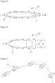
Fig. 1 is a side view of a conventional bullet. -
Fig. 2 is a side view of another conventional bullet. -
Fig. 3 is a schematic view showing force applied to a bullet. -
Fig. 4 is a schematic view showing a moving state of a bullet when the bullet is excessively rotated. -
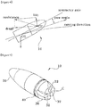
Fig. 5 is a perspective view of a bullet according to the present invention. -
Fig. 6 is a side view of the bullet according to the present invention. -
Fig. 7 is a perspective view showing a state that the center of gravity of the bullet is moved according to the present invention. -
Fig. 8 is a lower view enlargedly showing a structure of an air guiding recess formed at a tail part of the bullet according to the present invention. -
Fig. 9 is a schematic view showing a state that a bullet is discharged from a muzzle according to the present invention. -
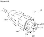
Fig. 10 is a perspective view showing an air flow generated during flight of the bullet according to the present invention. - Hereinafter, the embodiments of the present invention will be described in detail with reference to accompanying drawings.
- As shown in
Figs. 5 and6 , abullet 10 according to the present invention consists of ahead part 20, and atail part 30 which is formed at the rear side of the head part and formed with air guidingrecesses 32. - The
head part 20 formed at the front side of bullet has a streamlined front end in order to reduce air resistance during flight of the bullet. - The
tail part 30 is integrally formed with thehead part 20 and formed into a boat-tail shape which is inclined at about 6~8° with respect to a center axis of the bullet in order to allow air to be smoothly flowed during the flight of the bullet and also to minimize generation of vortex at the rear side of the bullet. - Since the boat-tail shape of the bullet is well-known already, the structure and effect thereof will be omitted.
- The air guiding
recesses 32 formed at thetail part 30 function to guide the air flow on a surface of the bullet. - The air guiding
recesses 32 are formed in an odd number at outer and lower surfaces of thetail part 30. Each of the air guidingrecesses 32 has an inclined bottom so that a depth of theair guiding recess 32 is gradually increased toward the lower surface of thetail part 30. Thus, during the flight of the bullet, the air flow is forcibly guided to the center area of the lower surface of thetail part 30, thereby efficiently restraining irregular air flow, i.e., vortex generated at the rear side of thebullet 10. - If the air guiding
recesses 32 are formed at thetail part 30, as described above, air is guided and flowed through the air guidingrecesses 32. Herein, it is necessary to maintain balance among the guided air flows. It is easy to maintain the balance when the air guidingrecesses 32 are formed in an odd number, and thus the flight stability of the bullet is kept. - Each of the air guiding
recesses 32 which is formed at the outer and lower surfaces of thetail part 30 has the same width over the whole length thereof so that the air flow guided by the air guidingrecesses 32 is stabilized therein. - And in order to more effectively restrain the generation of vortex, it is preferable that each end of the air guiding recesses 32 formed at the lower surface of the
tail part 30 is located to be adjacent to the center point of thetail part 30. - The air guiding recesses 32 also function to minimize a yaw angle occurred during the flight of the
bullet 10, thereby securing the flight stability of thebullet 10. In other words, since the multiple air guiding recesses 32 are formed at the outer surface of thebullet 10, the entire mass of thetail part 30 is reduced, and as shown inFig. 7 , the center of gravity (CG) located at the rear side of thebullet 10 is moved toward the center of pressure (CP), and thus it is possible to reduce a yaw moment generated during the flight of thebullet 10 and also to remarkably reduce the yaw angle. - By restraining the generation of vortex and reducing the yaw moment and yaw angle, flight ability of the
bullet 10 is improved, and thus it is possible to considerably increase the effective range as well as the accuracy rate. - As shown in
Fig. 8 , each of the air guiding recesses 32 formed at thetail part 30 is curved in order to rotate the bullet using the air flow. Each curvedair guiding recess 32 has an angle θ with respect to a line which connects the center point C of the lower surface of thetail part 30 and the center of theair guiding recess 32 which is formed at the outer surface of thetail part 30, such that each end of the air guiding recesses 32 is not directed to the center point C of the lower surface of thetail part 30. In case that the air guiding recesses 32 are not directed to the center point C of the lower surface of thetail part 30, the air flows guided by the air guiding recesses 32 are collided with one another at the center point C, and thus the air flows are disturbed at the rear side of thebullet 10, thereby deteriorating the flight stability of thebullet 10. - As described above, due to the figural and structural features of the air guiding recesses 32, it is prevented that the vortex is generated at the rear side of the
bullet 10, and also the rotational force of thebullet 10 is additionally provided by the air flows guided by the air guiding recesses 32, thereby increasing the destructive power of thebullet 10. - A curvature of each of the air guiding recesses 32 can be properly adjusted within the extent that the air flow guided by the air guiding recesses 32 can provide the rotational force to the
bullet 10. - Preferably, three air guiding recesses 32 are formed in the outer surface of the
tail part 30 at regular intervals, and each of them has the same length, width and depth in order to provide the uniform air flows. - In order to decide the number of air guiding recesses 32 formed at the
bullet 10, the applicant preparedtest bullets 10 each of which has 3 to 6 air guiding recesses 32, performed a wind tunnel test using them and then observed a generation state of vortex at the rear side of thebullet 10. As a result, it was confirmed that the generation of vortex was minimized when having three air guiding recesses 32. - If the
bullet 10 formed with the air guiding recesses 32 as described above is shot from a gun, propellant gas is previously discharged through the air guiding recesses 32 when thebullet 10 leaves the muzzle of the gun, and thus pressure in the gun barrel is sharply reduced. Therefore, a shooting shock is remarkably reduced. - Meanwhile, a
reference numeral 40 which is not described is a cartridge belt. Thecartridge belt 40 is a belt which is formed of a soft metal and formed along the outer surface of thebullet 10 so that thebullet 10 can be spun with relation to the fringing groove formed in the gun barrel. - The air flow generated during the flight of the
bullet 10 having the configuration as described above will be described with reference toFig. 10 . - When the
bullet 10 is shot from a gun, the air flow is generated along the surface of the bullet10, and part of the air flow passing through thestreamlined head part 20 of thebullet 10 is guided to the multiple air guiding recesses 32 formed at the outer surface of thetail part 30. - Herein, the air flow guided to the air guiding recesses 32 is flowed at the angle θ and guided to the center area of the lower surface of the
bullet 10, thereby restraining the generation of the irregular air flow like vortex at the rear side of thebullet 10. - According to the present invention as described above, since air is forcibly guided to the center area of the tail part by the air guiding recesses formed at the tail part to have a predetermined depth, it is possible to easily and effectively restrain the vortex generated at the rear side of the tail part and thus increase the flight stability of the bullet, thereby improving the effective range and the accuracy rate.
- Further, since the mass of the tail part is reduced due to the air guiding recesses of the tail part, the center of gravity of the bullet is moved to the center of pressure thereof, and thus it is possible to considerably reduce the yaw angle generated during the flight of bullet, thereby improving the flight stability and accuracy rate of the bullet. Further, since the plurality of air guiding recesses are formed to be curved, the rotational force is applied to the bullet by the air guided through the air guiding recesses, thereby increasing the destructive power of the bullet.
- And since the propellant gas is previously discharged at the end of the shooting body (e.g., the muzzle of a gun) through each of the air guiding recesses, the shooting shock is remarkably reduced.
- While the present invention has been described with respect to the specific embodiments, it will be apparent to those skilled in the art that various changes and modifications may be made without departing from the scope of the invention as defined in the following claims.
Claims (2)
- A bullet (10) having air guiding recesses (32), comprising:
a head part (20); and
a tail part (4) which is located at the rear side of the head part (20) and formed with an odd number of air guiding recesses (32) formed at outer and lower surfaces,
wherein each of the air guiding recesses (32) has an inclined bottom so that a depth of the air guiding recess (32) is gradually increased toward the lower surface of the tail part (30). wherein the air guiding recesses are formed to be curved;
wherein each of the multiple air guiding recesses (32) has an angle (θ) with respect to a line which connects a center point (C) of the lower surface of the tail part (30) and a center of the air guiding recess (32) which is formed at the outer surface of the tail part (30), such that each end of the air guiding recesses (32) is not directed to the center point (C) of the lower surface of the tail part (30);
wherein each of the curved air guiding recesses (32) has the same width over the outer and lower surfaces of the tail part (30). - The bullet according to claim 1 , wherein three air guiding recesses (32) are formed at the outer and lower surfaces of the tail part (30) so as to be spaced apart from one another at regular intervals.
Applications Claiming Priority (2)
| Application Number | Priority Date | Filing Date | Title |
|---|---|---|---|
| KR1020100083800A KR101021055B1 (en) | 2010-08-30 | 2010-08-30 | Bullet with air guide groove |
| PCT/KR2011/003223 WO2012030048A2 (en) | 2010-08-30 | 2011-04-29 | Bullet including an air-guiding recess |
Publications (3)
| Publication Number | Publication Date |
|---|---|
| EP2613119A2 EP2613119A2 (en) | 2013-07-10 |
| EP2613119A4 EP2613119A4 (en) | 2015-10-07 |
| EP2613119B1 true EP2613119B1 (en) | 2017-04-26 |
Family
ID=43938687
Family Applications (1)
| Application Number | Title | Priority Date | Filing Date |
|---|---|---|---|
| EP11822023.5A Active EP2613119B1 (en) | 2010-08-30 | 2011-04-29 | Bullet including an air-guiding recess |
Country Status (6)
| Country | Link |
|---|---|
| US (1) | US8973504B2 (en) |
| EP (1) | EP2613119B1 (en) |
| KR (1) | KR101021055B1 (en) |
| IL (1) | IL224947A (en) |
| RU (1) | RU2535366C1 (en) |
| WO (1) | WO2012030048A2 (en) |
Families Citing this family (15)
| Publication number | Priority date | Publication date | Assignee | Title |
|---|---|---|---|---|
| AU2015288295C1 (en) * | 2014-04-30 | 2020-02-13 | G9 Holdings, Llc | Projectile with enhanced ballistics |
| USD1055200S1 (en) | 2014-04-30 | 2024-12-24 | G9 Holdings, Llc | Projectile |
| RU2597431C2 (en) * | 2014-08-26 | 2016-09-10 | Андрей Альбертович Половнев | Bullet ammunition for small arms |
| US9766049B2 (en) * | 2015-01-27 | 2017-09-19 | United Tactical Systems, Llc | Aerodynamic projectile |
| US10317178B2 (en) * | 2015-04-21 | 2019-06-11 | The United States Of America, As Represented By The Secretary Of The Navy | Optimized subsonic projectiles and related methods |
| KR101660887B1 (en) * | 2016-02-25 | 2016-09-28 | 주식회사 두레텍 | Bullet |
| US20180051967A1 (en) * | 2016-05-17 | 2018-02-22 | Todd Ronald Schwark | Self-spinning bullet and related methods of use |
| WO2018080199A2 (en) * | 2016-10-28 | 2018-05-03 | Jung, In | Projectile |
| KR101702955B1 (en) * | 2016-11-03 | 2017-02-09 | 주식회사 두레텍 | Bullet with Increased Effective Range |
| KR20180068080A (en) | 2016-12-13 | 2018-06-21 | 백수호 | Bullet |
| KR101800868B1 (en) * | 2017-06-12 | 2017-11-27 | 주식회사 두레텍 | A bullet having a gas curved path of a boat tail for discharging even compressed gas. |
| US11261890B2 (en) * | 2017-11-29 | 2022-03-01 | Khaled Abdullah Alhussan | High speed rotating bodies with transverse jets as a function of angle of attack, reynolds number, and velocity of the jet exit |
| US20190178616A1 (en) * | 2019-02-17 | 2019-06-13 | Dorian Robert Golej | Mushroom Bullet |
| DE102019116283A1 (en) * | 2019-06-14 | 2020-12-17 | Ruag Ammotec Gmbh | Projectile, method of making a projectile and ammunition |
| KR102185699B1 (en) | 2019-08-29 | 2020-12-02 | 유영민 | projectile having ogive |
Family Cites Families (14)
| Publication number | Priority date | Publication date | Assignee | Title |
|---|---|---|---|---|
| US760338A (en) * | 1903-07-15 | 1904-05-17 | Edward L Kwiatkowski | Projectile. |
| US871825A (en) * | 1906-09-07 | 1907-11-26 | Ludwig Schupmann | Projectile for rifled firearms. |
| US1241409A (en) * | 1916-12-22 | 1917-09-25 | Francisco Adolfo Lizarraga | Projectile. |
| US4176487A (en) * | 1970-11-18 | 1979-12-04 | Manis John R | Firearm barrels and projectiles |
| US3873048A (en) * | 1973-11-23 | 1975-03-25 | Us Army | Projectile boattails |
| US4063511A (en) | 1976-07-21 | 1977-12-20 | Bullard James M | Spinning shot gun projectile |
| US4813635A (en) * | 1986-12-29 | 1989-03-21 | United Technologies Corporation | Projectile with reduced base drag |
| JPH03221795A (en) * | 1990-01-29 | 1991-09-30 | Shigeru Sendai | S, c bullet |
| US5133261A (en) | 1990-06-25 | 1992-07-28 | Kelsey Jr Charles C | Devel small arms bullet |
| US5070791A (en) * | 1990-11-30 | 1991-12-10 | The United States Of America As Represented By The Secretary Of The Army | Projectile tail cone |
| US5932836A (en) * | 1997-09-09 | 1999-08-03 | Primex Technologies, Inc. | Range limited projectile using augmented roll damping |
| RU2200296C2 (en) * | 2000-12-26 | 2003-03-10 | Гаршин Олег Николаевич | Multipurpose ammunition |
| KR200437008Y1 (en) | 2006-10-27 | 2007-10-24 | 김도형 | Multipurpose lathe |
| KR20070075411A (en) * | 2007-06-27 | 2007-07-18 | 공주대학교 산학협력단 | Hunting shotgun bullets |
-
2010
- 2010-08-30 KR KR1020100083800A patent/KR101021055B1/en active Active
-
2011
- 2011-04-29 WO PCT/KR2011/003223 patent/WO2012030048A2/en not_active Ceased
- 2011-04-29 EP EP11822023.5A patent/EP2613119B1/en active Active
- 2011-04-29 US US13/819,690 patent/US8973504B2/en active Active
- 2011-04-29 RU RU2013114476/11A patent/RU2535366C1/en active
-
2013
- 2013-02-27 IL IL224947A patent/IL224947A/en active IP Right Grant
Also Published As
| Publication number | Publication date |
|---|---|
| KR101021055B1 (en) | 2011-03-14 |
| US8973504B2 (en) | 2015-03-10 |
| EP2613119A2 (en) | 2013-07-10 |
| WO2012030048A2 (en) | 2012-03-08 |
| US20130180424A1 (en) | 2013-07-18 |
| WO2012030048A3 (en) | 2012-04-26 |
| RU2535366C1 (en) | 2014-12-10 |
| RU2013114476A (en) | 2014-11-10 |
| IL224947A (en) | 2017-02-28 |
| EP2613119A4 (en) | 2015-10-07 |
Similar Documents
| Publication | Publication Date | Title |
|---|---|---|
| US8973504B2 (en) | Bullet including an air-guiding recess | |
| US11549789B2 (en) | Optimized subsonic projectiles | |
| RU2597431C2 (en) | Bullet ammunition for small arms | |
| CA1284061C (en) | Hunting ammunition comprising a bullet of increased effectiveness | |
| JP2022522872A5 (en) | ||
| ES2543196T5 (en) | Method of increasing the range of a small-caliber howitzer and long-range small-caliber howitzers | |
| WO2018130171A1 (en) | Weapon system consisting of multi-segment barrel and fluid-driven spinning projectile, and method | |
| KR20190047567A (en) | Projectile | |
| KR20130054284A (en) | Drag effect trajectory enhanced projectile | |
| GB2502507A (en) | Projectile holder for multiple projectiles | |
| CN206556504U (en) | The armament systems being made up of multisection type barrel and fluid forces spin bullet | |
| US8904941B2 (en) | Ammunition | |
| RU2406061C1 (en) | Armour-piercing bullet | |
| KR101800868B1 (en) | A bullet having a gas curved path of a boat tail for discharging even compressed gas. | |
| KR102354045B1 (en) | Sabot for projectile and assembly comprising the same | |
| US20040007148A1 (en) | Projectile with improved dynamic shape | |
| AU686954B2 (en) | Full caliber projectile for use against underwater objects | |
| RU2465543C1 (en) | "non-wad butterfly" bullet and cartridge for smooth-bore weapon | |
| US10684106B2 (en) | Aerodynamically contoured spinnable projectile | |
| RU2130581C1 (en) | Artillery shell | |
| RU2612692C1 (en) | Chursin bullet (options) | |
| RU2462685C1 (en) | Multielement cartridge of staroverov (versions) | |
| RU214533U1 (en) | Bullet | |
| KR101802040B1 (en) | Bullet | |
| RU2262651C2 (en) | Armor-piercing bullet |
Legal Events
| Date | Code | Title | Description |
|---|---|---|---|
| PUAI | Public reference made under article 153(3) epc to a published international application that has entered the european phase |
Free format text: ORIGINAL CODE: 0009012 |
|
| 17P | Request for examination filed |
Effective date: 20130402 |
|
| AK | Designated contracting states |
Kind code of ref document: A2 Designated state(s): AL AT BE BG CH CY CZ DE DK EE ES FI FR GB GR HR HU IE IS IT LI LT LU LV MC MK MT NL NO PL PT RO RS SE SI SK SM TR |
|
| DAX | Request for extension of the european patent (deleted) | ||
| REG | Reference to a national code |
Ref country code: DE Ref legal event code: R079 Ref document number: 602011037414 Country of ref document: DE Free format text: PREVIOUS MAIN CLASS: F42B0030040000 Ipc: F42B0010440000 |
|
| A4 | Supplementary search report drawn up and despatched |
Effective date: 20150908 |
|
| RIC1 | Information provided on ipc code assigned before grant |
Ipc: F42B 10/44 20060101AFI20150902BHEP |
|
| GRAP | Despatch of communication of intention to grant a patent |
Free format text: ORIGINAL CODE: EPIDOSNIGR1 |
|
| INTG | Intention to grant announced |
Effective date: 20170124 |
|
| GRAS | Grant fee paid |
Free format text: ORIGINAL CODE: EPIDOSNIGR3 |
|
| GRAA | (expected) grant |
Free format text: ORIGINAL CODE: 0009210 |
|
| REG | Reference to a national code |
Ref country code: FR Ref legal event code: PLFP Year of fee payment: 7 |
|
| AK | Designated contracting states |
Kind code of ref document: B1 Designated state(s): AL AT BE BG CH CY CZ DE DK EE ES FI FR GB GR HR HU IE IS IT LI LT LU LV MC MK MT NL NO PL PT RO RS SE SI SK SM TR |
|
| REG | Reference to a national code |
Ref country code: GB Ref legal event code: FG4D |
|
| REG | Reference to a national code |
Ref country code: CH Ref legal event code: EP |
|
| REG | Reference to a national code |
Ref country code: AT Ref legal event code: REF Ref document number: 888268 Country of ref document: AT Kind code of ref document: T Effective date: 20170515 |
|
| REG | Reference to a national code |
Ref country code: IE Ref legal event code: FG4D |
|
| REG | Reference to a national code |
Ref country code: DE Ref legal event code: R096 Ref document number: 602011037414 Country of ref document: DE |
|
| REG | Reference to a national code |
Ref country code: NL Ref legal event code: MP Effective date: 20170426 |
|
| REG | Reference to a national code |
Ref country code: LT Ref legal event code: MG4D |
|
| REG | Reference to a national code |
Ref country code: AT Ref legal event code: MK05 Ref document number: 888268 Country of ref document: AT Kind code of ref document: T Effective date: 20170426 |
|
| PG25 | Lapsed in a contracting state [announced via postgrant information from national office to epo] |
Ref country code: NL Free format text: LAPSE BECAUSE OF FAILURE TO SUBMIT A TRANSLATION OF THE DESCRIPTION OR TO PAY THE FEE WITHIN THE PRESCRIBED TIME-LIMIT Effective date: 20170426 |
|
| PG25 | Lapsed in a contracting state [announced via postgrant information from national office to epo] |
Ref country code: GR Free format text: LAPSE BECAUSE OF FAILURE TO SUBMIT A TRANSLATION OF THE DESCRIPTION OR TO PAY THE FEE WITHIN THE PRESCRIBED TIME-LIMIT Effective date: 20170727 Ref country code: HR Free format text: LAPSE BECAUSE OF FAILURE TO SUBMIT A TRANSLATION OF THE DESCRIPTION OR TO PAY THE FEE WITHIN THE PRESCRIBED TIME-LIMIT Effective date: 20170426 Ref country code: NO Free format text: LAPSE BECAUSE OF FAILURE TO SUBMIT A TRANSLATION OF THE DESCRIPTION OR TO PAY THE FEE WITHIN THE PRESCRIBED TIME-LIMIT Effective date: 20170726 Ref country code: AT Free format text: LAPSE BECAUSE OF FAILURE TO SUBMIT A TRANSLATION OF THE DESCRIPTION OR TO PAY THE FEE WITHIN THE PRESCRIBED TIME-LIMIT Effective date: 20170426 Ref country code: ES Free format text: LAPSE BECAUSE OF FAILURE TO SUBMIT A TRANSLATION OF THE DESCRIPTION OR TO PAY THE FEE WITHIN THE PRESCRIBED TIME-LIMIT Effective date: 20170426 Ref country code: LT Free format text: LAPSE BECAUSE OF FAILURE TO SUBMIT A TRANSLATION OF THE DESCRIPTION OR TO PAY THE FEE WITHIN THE PRESCRIBED TIME-LIMIT Effective date: 20170426 Ref country code: FI Free format text: LAPSE BECAUSE OF FAILURE TO SUBMIT A TRANSLATION OF THE DESCRIPTION OR TO PAY THE FEE WITHIN THE PRESCRIBED TIME-LIMIT Effective date: 20170426 |
|
| PG25 | Lapsed in a contracting state [announced via postgrant information from national office to epo] |
Ref country code: IS Free format text: LAPSE BECAUSE OF FAILURE TO SUBMIT A TRANSLATION OF THE DESCRIPTION OR TO PAY THE FEE WITHIN THE PRESCRIBED TIME-LIMIT Effective date: 20170826 Ref country code: LV Free format text: LAPSE BECAUSE OF FAILURE TO SUBMIT A TRANSLATION OF THE DESCRIPTION OR TO PAY THE FEE WITHIN THE PRESCRIBED TIME-LIMIT Effective date: 20170426 Ref country code: BG Free format text: LAPSE BECAUSE OF FAILURE TO SUBMIT A TRANSLATION OF THE DESCRIPTION OR TO PAY THE FEE WITHIN THE PRESCRIBED TIME-LIMIT Effective date: 20170726 Ref country code: PL Free format text: LAPSE BECAUSE OF FAILURE TO SUBMIT A TRANSLATION OF THE DESCRIPTION OR TO PAY THE FEE WITHIN THE PRESCRIBED TIME-LIMIT Effective date: 20170426 Ref country code: RS Free format text: LAPSE BECAUSE OF FAILURE TO SUBMIT A TRANSLATION OF THE DESCRIPTION OR TO PAY THE FEE WITHIN THE PRESCRIBED TIME-LIMIT Effective date: 20170426 Ref country code: SE Free format text: LAPSE BECAUSE OF FAILURE TO SUBMIT A TRANSLATION OF THE DESCRIPTION OR TO PAY THE FEE WITHIN THE PRESCRIBED TIME-LIMIT Effective date: 20170426 |
|
| REG | Reference to a national code |
Ref country code: CH Ref legal event code: PL |
|
| REG | Reference to a national code |
Ref country code: IE Ref legal event code: MM4A |
|
| REG | Reference to a national code |
Ref country code: DE Ref legal event code: R097 Ref document number: 602011037414 Country of ref document: DE |
|
| PG25 | Lapsed in a contracting state [announced via postgrant information from national office to epo] |
Ref country code: SK Free format text: LAPSE BECAUSE OF FAILURE TO SUBMIT A TRANSLATION OF THE DESCRIPTION OR TO PAY THE FEE WITHIN THE PRESCRIBED TIME-LIMIT Effective date: 20170426 Ref country code: RO Free format text: LAPSE BECAUSE OF FAILURE TO SUBMIT A TRANSLATION OF THE DESCRIPTION OR TO PAY THE FEE WITHIN THE PRESCRIBED TIME-LIMIT Effective date: 20170426 Ref country code: MC Free format text: LAPSE BECAUSE OF FAILURE TO SUBMIT A TRANSLATION OF THE DESCRIPTION OR TO PAY THE FEE WITHIN THE PRESCRIBED TIME-LIMIT Effective date: 20170426 Ref country code: DK Free format text: LAPSE BECAUSE OF FAILURE TO SUBMIT A TRANSLATION OF THE DESCRIPTION OR TO PAY THE FEE WITHIN THE PRESCRIBED TIME-LIMIT Effective date: 20170426 Ref country code: EE Free format text: LAPSE BECAUSE OF FAILURE TO SUBMIT A TRANSLATION OF THE DESCRIPTION OR TO PAY THE FEE WITHIN THE PRESCRIBED TIME-LIMIT Effective date: 20170426 Ref country code: CZ Free format text: LAPSE BECAUSE OF FAILURE TO SUBMIT A TRANSLATION OF THE DESCRIPTION OR TO PAY THE FEE WITHIN THE PRESCRIBED TIME-LIMIT Effective date: 20170426 |
|
| PG25 | Lapsed in a contracting state [announced via postgrant information from national office to epo] |
Ref country code: IT Free format text: LAPSE BECAUSE OF FAILURE TO SUBMIT A TRANSLATION OF THE DESCRIPTION OR TO PAY THE FEE WITHIN THE PRESCRIBED TIME-LIMIT Effective date: 20170426 Ref country code: LU Free format text: LAPSE BECAUSE OF NON-PAYMENT OF DUE FEES Effective date: 20170429 Ref country code: SM Free format text: LAPSE BECAUSE OF FAILURE TO SUBMIT A TRANSLATION OF THE DESCRIPTION OR TO PAY THE FEE WITHIN THE PRESCRIBED TIME-LIMIT Effective date: 20170426 Ref country code: LI Free format text: LAPSE BECAUSE OF NON-PAYMENT OF DUE FEES Effective date: 20170430 Ref country code: CH Free format text: LAPSE BECAUSE OF NON-PAYMENT OF DUE FEES Effective date: 20170430 |
|
| PLBE | No opposition filed within time limit |
Free format text: ORIGINAL CODE: 0009261 |
|
| STAA | Information on the status of an ep patent application or granted ep patent |
Free format text: STATUS: NO OPPOSITION FILED WITHIN TIME LIMIT |
|
| REG | Reference to a national code |
Ref country code: BE Ref legal event code: MM Effective date: 20170430 |
|
| 26N | No opposition filed |
Effective date: 20180129 |
|
| REG | Reference to a national code |
Ref country code: FR Ref legal event code: PLFP Year of fee payment: 8 |
|
| PG25 | Lapsed in a contracting state [announced via postgrant information from national office to epo] |
Ref country code: IE Free format text: LAPSE BECAUSE OF NON-PAYMENT OF DUE FEES Effective date: 20170429 |
|
| PG25 | Lapsed in a contracting state [announced via postgrant information from national office to epo] |
Ref country code: SI Free format text: LAPSE BECAUSE OF FAILURE TO SUBMIT A TRANSLATION OF THE DESCRIPTION OR TO PAY THE FEE WITHIN THE PRESCRIBED TIME-LIMIT Effective date: 20170426 Ref country code: BE Free format text: LAPSE BECAUSE OF NON-PAYMENT OF DUE FEES Effective date: 20170430 |
|
| PG25 | Lapsed in a contracting state [announced via postgrant information from national office to epo] |
Ref country code: MT Free format text: LAPSE BECAUSE OF NON-PAYMENT OF DUE FEES Effective date: 20170429 |
|
| PG25 | Lapsed in a contracting state [announced via postgrant information from national office to epo] |
Ref country code: HU Free format text: LAPSE BECAUSE OF FAILURE TO SUBMIT A TRANSLATION OF THE DESCRIPTION OR TO PAY THE FEE WITHIN THE PRESCRIBED TIME-LIMIT; INVALID AB INITIO Effective date: 20110429 |
|
| PG25 | Lapsed in a contracting state [announced via postgrant information from national office to epo] |
Ref country code: CY Free format text: LAPSE BECAUSE OF NON-PAYMENT OF DUE FEES Effective date: 20170426 |
|
| PG25 | Lapsed in a contracting state [announced via postgrant information from national office to epo] |
Ref country code: MK Free format text: LAPSE BECAUSE OF FAILURE TO SUBMIT A TRANSLATION OF THE DESCRIPTION OR TO PAY THE FEE WITHIN THE PRESCRIBED TIME-LIMIT Effective date: 20170426 |
|
| PG25 | Lapsed in a contracting state [announced via postgrant information from national office to epo] |
Ref country code: TR Free format text: LAPSE BECAUSE OF FAILURE TO SUBMIT A TRANSLATION OF THE DESCRIPTION OR TO PAY THE FEE WITHIN THE PRESCRIBED TIME-LIMIT Effective date: 20170426 |
|
| PG25 | Lapsed in a contracting state [announced via postgrant information from national office to epo] |
Ref country code: PT Free format text: LAPSE BECAUSE OF FAILURE TO SUBMIT A TRANSLATION OF THE DESCRIPTION OR TO PAY THE FEE WITHIN THE PRESCRIBED TIME-LIMIT Effective date: 20170426 |
|
| PG25 | Lapsed in a contracting state [announced via postgrant information from national office to epo] |
Ref country code: AL Free format text: LAPSE BECAUSE OF FAILURE TO SUBMIT A TRANSLATION OF THE DESCRIPTION OR TO PAY THE FEE WITHIN THE PRESCRIBED TIME-LIMIT Effective date: 20170426 |
|
| REG | Reference to a national code |
Ref country code: FR Ref legal event code: PLFP Year of fee payment: 13 |
|
| P01 | Opt-out of the competence of the unified patent court (upc) registered |
Effective date: 20230514 |
|
| PGFP | Annual fee paid to national office [announced via postgrant information from national office to epo] |
Ref country code: GB Payment date: 20260423 Year of fee payment: 16 |
|
| PGFP | Annual fee paid to national office [announced via postgrant information from national office to epo] |
Ref country code: DE Payment date: 20260422 Year of fee payment: 16 |
|
| PGFP | Annual fee paid to national office [announced via postgrant information from national office to epo] |
Ref country code: FR Payment date: 20260422 Year of fee payment: 16 |