EP2613094A1 - Heating cooker - Google Patents
Heating cooker Download PDFInfo
- Publication number
- EP2613094A1 EP2613094A1 EP11821707.4A EP11821707A EP2613094A1 EP 2613094 A1 EP2613094 A1 EP 2613094A1 EP 11821707 A EP11821707 A EP 11821707A EP 2613094 A1 EP2613094 A1 EP 2613094A1
- Authority
- EP
- European Patent Office
- Prior art keywords
- exhaust
- exhaust duct
- inlet
- heating cooker
- casing
- Prior art date
- Legal status (The legal status is an assumption and is not a legal conclusion. Google has not performed a legal analysis and makes no representation as to the accuracy of the status listed.)
- Withdrawn
Links
- 238000010438 heat treatment Methods 0.000 title claims abstract description 168
- 238000005192 partition Methods 0.000 claims description 10
- 239000000203 mixture Substances 0.000 claims description 5
- 238000001816 cooling Methods 0.000 abstract description 115
- XLYOFNOQVPJJNP-UHFFFAOYSA-N water Substances O XLYOFNOQVPJJNP-UHFFFAOYSA-N 0.000 description 39
- 238000010411 cooking Methods 0.000 description 22
- 238000003756 stirring Methods 0.000 description 10
- 210000001364 upper extremity Anatomy 0.000 description 7
- 230000003247 decreasing effect Effects 0.000 description 6
- 230000000694 effects Effects 0.000 description 5
- 229920006395 saturated elastomer Polymers 0.000 description 4
- QVGXLLKOCUKJST-UHFFFAOYSA-N atomic oxygen Chemical compound [O] QVGXLLKOCUKJST-UHFFFAOYSA-N 0.000 description 3
- 239000001301 oxygen Substances 0.000 description 3
- 229910052760 oxygen Inorganic materials 0.000 description 3
- 230000015556 catabolic process Effects 0.000 description 2
- 238000009833 condensation Methods 0.000 description 2
- 230000005494 condensation Effects 0.000 description 2
- 230000007797 corrosion Effects 0.000 description 2
- 238000005260 corrosion Methods 0.000 description 2
- 238000010790 dilution Methods 0.000 description 2
- 239000012895 dilution Substances 0.000 description 2
- 210000003414 extremity Anatomy 0.000 description 2
- 239000004973 liquid crystal related substance Substances 0.000 description 2
- 150000003839 salts Chemical class 0.000 description 2
- 229920003002 synthetic resin Polymers 0.000 description 2
- 239000000057 synthetic resin Substances 0.000 description 2
- 238000009792 diffusion process Methods 0.000 description 1
- 238000007599 discharging Methods 0.000 description 1
- 230000005489 elastic deformation Effects 0.000 description 1
- 239000007789 gas Substances 0.000 description 1
- 239000011521 glass Substances 0.000 description 1
- 238000003780 insertion Methods 0.000 description 1
- 230000037431 insertion Effects 0.000 description 1
- 239000011810 insulating material Substances 0.000 description 1
- 230000007246 mechanism Effects 0.000 description 1
- 230000004048 modification Effects 0.000 description 1
- 238000012986 modification Methods 0.000 description 1
- 230000003647 oxidation Effects 0.000 description 1
- 238000007254 oxidation reaction Methods 0.000 description 1
- 239000000779 smoke Substances 0.000 description 1
- 239000000243 solution Substances 0.000 description 1
- 239000008400 supply water Substances 0.000 description 1
- 238000011144 upstream manufacturing Methods 0.000 description 1
Images







Classifications
-
- H—ELECTRICITY
- H05—ELECTRIC TECHNIQUES NOT OTHERWISE PROVIDED FOR
- H05B—ELECTRIC HEATING; ELECTRIC LIGHT SOURCES NOT OTHERWISE PROVIDED FOR; CIRCUIT ARRANGEMENTS FOR ELECTRIC LIGHT SOURCES, IN GENERAL
- H05B6/00—Heating by electric, magnetic or electromagnetic fields
- H05B6/64—Heating using microwaves
- H05B6/6402—Aspects relating to the microwave cavity
-
- F—MECHANICAL ENGINEERING; LIGHTING; HEATING; WEAPONS; BLASTING
- F24—HEATING; RANGES; VENTILATING
- F24C—DOMESTIC STOVES OR RANGES ; DETAILS OF DOMESTIC STOVES OR RANGES, OF GENERAL APPLICATION
- F24C15/00—Details
- F24C15/20—Removing cooking fumes
- F24C15/2007—Removing cooking fumes from oven cavities
-
- H—ELECTRICITY
- H05—ELECTRIC TECHNIQUES NOT OTHERWISE PROVIDED FOR
- H05B—ELECTRIC HEATING; ELECTRIC LIGHT SOURCES NOT OTHERWISE PROVIDED FOR; CIRCUIT ARRANGEMENTS FOR ELECTRIC LIGHT SOURCES, IN GENERAL
- H05B6/00—Heating by electric, magnetic or electromagnetic fields
- H05B6/64—Heating using microwaves
- H05B6/642—Cooling of the microwave components and related air circulation systems
-
- H—ELECTRICITY
- H05—ELECTRIC TECHNIQUES NOT OTHERWISE PROVIDED FOR
- H05B—ELECTRIC HEATING; ELECTRIC LIGHT SOURCES NOT OTHERWISE PROVIDED FOR; CIRCUIT ARRANGEMENTS FOR ELECTRIC LIGHT SOURCES, IN GENERAL
- H05B6/00—Heating by electric, magnetic or electromagnetic fields
- H05B6/64—Heating using microwaves
- H05B6/647—Aspects related to microwave heating combined with other heating techniques
- H05B6/6473—Aspects related to microwave heating combined with other heating techniques combined with convection heating
- H05B6/6479—Aspects related to microwave heating combined with other heating techniques combined with convection heating using steam
Definitions
- the present invention relates to a heating cooker.
- Patent Literature 1 JP 2008-116094 A (Patent Literature 1), for instance).
- the applicants have conceived a heating cooker that is capable of mixing in an exhaust duct a portion of air, from a cooling fan for cooling electric components in a main body, with exhaust from inside of a heating chamber and thereafter discharging the mixed exhaust from front face side of the main body.
- the heating cooker is described in order to facilitate understanding of the invention and is neither publicly known art nor the prior art.
- An object of the invention is to provide a heating cooker that prevents exhaust from inside of a heating chamber from flowing into a main body thereof even if a fan for supplying air that is to be mixed with the exhaust breaks down.
- a heating cooker of the invention comprises:
- the highly heated exhaust containing steam from the inside of the heating chamber is guided by the exhaust path to the front face side of the casing and flows through the exhaust path and the exhaust inlet into the exhaust duct when cooking is performed.
- the exhaust that has flowed into the exhaust duct is mixed with the portion of the air from the fan that has flowed in through the air inflow port and is forced to be discharged to the outside through the discharge port by wind pressure of the air from the fan.
- the mixed exhaust mixed in the exhaust duct can be discharged from the front face side of a main body thereof.
- the position along the height direction of the air inflow port into which the air flows from under the exhaust duct is lower than the position along the height direction of the discharge port of the exhaust duct, and the position along the height direction of the air inflow port of the exhaust duct is lower than the position along the height direction of the exhaust inlet of the exhaust duct, so that the exhaust that flows through the exhaust inlet of the exhaust duct into the exhaust duct when the fan is stopped due to breakdown or the like is prevented from flowing out through the air inflow port that is in the lowest position because the exhaust is initially and gradually accumulated from upside in the exhaust duct and is thereafter discharged to the outside through the discharge port that is in the higher position along the height direction than the air inflow port. Accordingly, the exhaust from the inside of the heating chamber can be prevented from flowing into the casing even if the fan for supplying air that is to be mixed with the exhaust breaks down.
- the exhaust inlet is provided in an air path between the air inflow port and the discharge port in the exhaust duct, and wherein a shield wall is provided between the air inflow port and the exhaust inlet in the exhaust duct.
- flow of the exhaust that has flowed in from the inside of the heating chamber through the exhaust path and the exhaust inlet can be prevented from being disturbed by the air that has flowed in from the air inflow port and from being reversed toward the exhaust inlet, by the provision of the exhaust inlet in the air path between the air inflow port and the discharge port in the exhaust duct and the provision of the shield wall between the air inflow port and the exhaust inlet.
- the shield wall is a wall that has a section shaped like a letter U so as to surround a side for the air inflow port, of a columnar region extended from the exhaust inlet into the exhaust duct and so as to open on a side of the columnar region for the discharge port.
- the exhaust from the exhaust inlet can be drawn into the exhaust duct by ejector effect owing to difference in flow velocity between flow of the air from the air inflow port and the exhaust from the exhaust inlet, because the shield wall opens on the side for the discharge port in the air path from the air inflow port to the discharge port, with use of the shield wall that has the section shaped like a letter U so as to surround the side for the air inflow port, of the columnar region extended from the exhaust inlet into the exhaust duct and so as to open on the side of the columnar region for the discharge port.
- the exhaust flowing in through the exhaust inlet can smoothly be merged with the air from the air inflow port.
- the exhaust duct comprises a plurality of the discharge ports.
- the air inflow port is placed in a region except a region immediately under the exhaust inlet in the exhaust duct.
- the placement of the air inflow port in the region except the region immediately under the exhaust inlet in the exhaust duct prevents leakage of the water through the air inflow port that is lower in position along the height direction than the exhaust inlet.
- the exhaust duct is bent between the air inflow port and the discharge ports and on a position that is nearer to the discharge ports than to the exhaust inlet.
- the exhaust duct is bent between the air inflow port and the discharge ports and on the side of the exhaust inlet that is nearer to the discharge ports in the exhaust duct, the exhaust that has flowed through the exhaust inlet into the exhaust duct is mixed with the portion of the air from the fan that has flowed in through the air inflow port, in the air path between the air inflow port and the discharge ports, and the mixed exhaust is thereafter turned and guided to the discharge ports.
- efficient mixture of the exhaust and the air results in uniform temperature of the mixed exhaust that is discharged to the outside through the discharge ports and prevents discharge of highly heated exhaust with biased temperature distribution.
- bottom part in the exhaust duct has an inclined surface that gradually lowers from side of the exhaust inlet toward side of the discharge ports.
- the bottom part of the exhaust duct having the inclined surface that gradually lowers from the side of the exhaust inlet toward the side of the discharge ports causes the condensate water to flow from the side of the exhaust inlet toward the side of the discharge ports along the inclined surface on the bottom part of the exhaust duct and to be discharged to the outside through the discharge ports and prevents the condensate water from being accumulated in the exhaust duct.
- a partition wall of which top end is higher than the bottom part immediately under the exhaust inlet in the exhaust duct is provided in an air path between the air inflow port and the exhaust inlet in the exhaust duct.
- the partition wall of which the top end is higher than the bottom part immediately under the exhaust inlet in the exhaust duct and which is provided in the air path between the air inflow port and the exhaust inlet in the exhaust duct prevents the condensate water from flowing toward the air inflow port that is lower in position along the height direction than the exhaust inlet.
- the exhaust duct comprises drain guide grooves that are provided on outside of side walls of the exhaust duct and that guide drain from the side of the exhaust inlet toward the side of the discharge ports and a drain port that is provided on a side nearer to the discharge ports than to the exhaust inlet in the drain guide grooves.
- the exhaust duct having the drain guide grooves that are provided on the outside of the side walls of the exhaust duct and that guides drain from the side of the exhaust inlet toward the side of the discharge ports and the drain port that is provided on the side nearer to the discharge ports than to the exhaust inlet in the drain guide grooves condensate water produced in the casing and/or the like, for instance, is received and gathered, and the gathered drain is thereafter guided toward the drain port by the drain guide grooves of the exhaust duct and is discharged through the drain port to the outside.
- the exhaust duct can be cooled, temperature of the mixed exhaust in the exhaust duct can be decreased, and effect of cooling the exhaust can be improved.
- the one exhaust duct is capable of combining exhaust disposal function and drain disposal function.
- the heating cooker in accordance with an embodiment comprises a dew receiving container that is placed under the opening of the heating chamber, that receives the exhaust from the discharge ports of the exhaust duct, and that diffuses the exhaust to outside of the casing.
- the mixed exhaust from the discharge ports of the exhaust duct is received and is diffused to the outside of the casing by the dew receiving container that is placed under the opening of the heating chamber, the mixed exhaust having a decreased temperature by being cooled can be received by the dew receiving container on the front face side and can be diffused to vast outside space on the front face side of the casing.
- the heating cooker of the invention can be provided that prevents the exhaust from the inside of the heating chamber from flowing into the main body thereof even if the fan for supplying the air that is to be mixed with the exhaust breaks down.
- Fig. 1 is a front view of the heating cooker in accordance with the embodiment of the invention.
- the heating cooker has a casing 1 and a door 2 with a handle, as an example of a door that is mounted on front face side of the casing 1.
- Heat resistant glass 5 is mounted at general center of the door 2 with handle.
- An operation panel 3 is provided on the front face side of the casing 1 so as to adjoin the door 2 with handle that is closed.
- a dew receiving container 4 as an example of an exhaust receiving part is provided under the door 2 with handle and the operation panel 3.
- the operation panel 3 has a liquid crystal display part 7, which provides a display according to an operation.
- the dew receiving container 4 is a container that is attachable to and detachable from two front legs 6, 6 provided on front side on bottom part of the casing 1. Once the dew receiving container 4 is inserted to underside of the casing 1 from the front side toward rear side and is mounted on the front legs 6, 6, a portion of the dew receiving container 4 is positioned under a rear face (back face) of the door 2 with handle that is closed. Thus condensate water deposited on the rear face of the door 2 with handle drops into the dew receiving container 4 placed under an opening 8a (shown in Fig. 8 ) of the heating chamber 8 (shown in Fig. 8 ) when the door 2 with handle is opened.
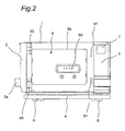
- Fig. 2 shows a front view of the heating cooker with the door 2 with handle fully opened, as seen looking from the front face side
- Fig. 3 shows a top plan view of the heating cooker.
- the same components as those of the heating cooker shown in Fig. 1 are provided with the same reference numerals.
- the heating chamber 8 for heating an object 23 (see Fig. 4 ) to be heated is provided in the casing 1.
- the door 2 with handle that is provided on the front face side of the casing 1 pivots in left and right directions on left side end part of the casing 1 and opens and closes the opening 8a (shown in Fig. 8 ) on the front face of the heating chamber 8 (shown in Fig. 4 ).
- the door 2 with handle is pivotably mounted through hinges (not shown) on a side part of the casing 1 that is opposed to the operation panel 3.
- Latch hooks 90, 90 are provided on right side and on the rear face of the door 2 with handle.
- the latch hooks 90, 90 are inserted into insertion holes 91, 91 provided on periphery of the opening 8a and are releasably engaged with latch mechanisms (not shown) in the casing 1.
- the engagement of the latch hooks 90, 90 can be released by a grasp by a user on a handle 2a of the door 2 with handle.
- numeral 80 denotes steam blow-off ports through which steam produced by a steam producing device 13 (shown in Fig. 5 ) is blown into the heating chamber 8.
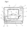
- Fig. 4 shows a schematic section of the heating cooker.
- numeral 26 denotes heaters placed on upper side in the heating chamber 8.
- a portion of air taken in by a cooling fan 16 from outside through an air intake 17 passes through an electric component chamber 9 as an example of a cooling space and thereafter flows into the heating chamber 8 through an air supply port 8b that is in open state with opening of an air supply damper 50.
- the other portion of the air taken in from the outside passes through the electric component chamber 9, thereafter flows to bottom part side of the casing 1, and then flows through an air path under the heating chamber 8 into a cooling air inlet 102 as an example of an air inflow port of an exhaust duct 100.
- the portion of the air in the heating chamber 8 is discharged into the exhaust duct 100 through an exhaust port 8c and an exhaust tube 18 as an example of an exhaust path and is mixed with air having flowed in through an exhaust inlet 101, in the exhaust duct 100. Then the exhaust diluted in the exhaust duct 100 is blown downward through four discharge ports 104 into the dew receiving container 4.
- the portion of the air that flows to the bottom part side of the casing 1 and that then flows through the air path under the heating chamber 8 is blown through a plurality of cooling air blow-off ports 70, provided on the front face side on a bottom plate 30 (shown in Fig. 9 ) of the casing 1, toward a region S ( Fig. 17 ) in the dew receiving container 4 that receives and diffuses the exhaust from the discharge ports 104.
- Fig. 5 shows a perspective view of the heating cooker from which the casing 1 has been removed, as seen looking from rear and diagonally upper side.
- the heating chamber 8 for heating the object 23 (shown in Fig. 4 ) to be heated is provided in the casing 1.
- the electric component chamber 9 as the example of the cooling space is provided on a lateral side of the heating chamber 8 and on the rear side of the operation panel 3, and an air intake space 10 is provided on the rear side of the heating chamber 8 and on the rear side of the electric component chamber 9.
- Heat shield plates 11, 11, ... are provided on top, bottom, rear side, and both lateral sides of the heating chamber 8, respectively. That is, the heat shield plates 11, 11, ... are provided around the heating chamber 8 except for the opening 8a. Spaces between the heat shield plates 11 and the heating chamber 8 are filled with heat insulating material (not shown).
- the steam producing device 3 for producing steam that is supplied into the heating chamber 8 is provided on the rear face side of the heating chamber 8, and a water supply pump (not shown) connected to the steam producing device 13 through a water supply tube is provided under the heating chamber 8.
- a tank housing part 15 in which a water supply tank (not shown) is housed, a magnetron 51, a power supply transformer 52 and the like are provided in the electric component chamber 9 in the casing 1.
- air outside the casing 1 flows through a plurality of air intakes (not shown) into the air intake space 10.
- the air in the air intake space 10 is delivered into the electric component chamber 9 by the cooling fan 16.
- the air intakes are each composed of a plurality of slits provided in rear part of the casing 1.
- numeral 21 denotes a partition wall that serves as a partition between the electric component chamber 9 and the air intake space 10.
- the cooling fan 16 is mounted on the partition wall 21.
- the heaters 26 are provided on the upper side in the heating chamber 8. Microwaves produced by the magnetron 51 are guided through a waveguide (not shown) to center of lower part in the heating chamber 8, are radiated toward upside in the heating chamber 8 while being stirred by a rotating antenna (not shown), and thereby heat the object 23 (shown in Fig. 4 ) to be heated.
- Water in the water supply tank housed in the housing part 15 is supplied through the water supply tube (not shown) to the steam producing device 13 by drive of the water supply pump.
- the steam producing device 13 heats the water from the water supply pump by a steam producing heater 24 and thereby produces steam.
- Fig. 6 shows a perspective view of the heating cooker from which the casing 1 has been removed, as seen looking from front and diagonally upper side
- Fig. 7 shows a left side view of the heating cooker from which the casing 1 has been removed.
- an upstream end of the exhaust tube 18 is connected to the exhaust port 8c (shown in Fig. 4 ) provided on a left side wall of the heating chamber 8, and a downstream end (exhaust outlet) of the exhaust tube 18 is connected to the exhaust duct 100 made of synthetic resin and provided on lower left side and the front face side in the casing 1.
- the exhaust tube 18 is made of synthetic resin having flexibility.
- Gas in the heating chamber 8 is guided from a side part to the front face side of the casing 1 by the exhaust tube 18 and the exhaust duct 100 and is then discharged to the outside of the casing 1.
- An extremity part of a drain groove 110 is connected to a drain receiving part 111 on the rear face side of the exhaust duct 100.
- the drain groove 110 receives condensate water dropping along side faces of the heat shield plates 11 that cover the heating chamber 8.
- the drain groove 110 is omitted in Fig. 7 .
- Fig. 8 shows a perspective view of the heating cooker from which the casing 1 and the bottom plate 30 (shown in Fig. 9 ) have been removed, as seen looking from front and diagonally lower side, and the exhaust duct 100 shaped like a letter L is placed on a corner part on front left and lower side of the casing 1.
- the cooling air inlet 102 is provided on the rear face side and lower side of the exhaust duct 100 so that opening thereof faces downward, the four discharge ports 104 are provided at specified intervals along left and right direction on the front face side and the lower side of the exhaust duct 100, and a drain port 105 is provided at right of the discharge ports 104.
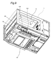
- Fig. 9 shows a perspective view of the heating cooker which is shown in Fig. 8 and on which the bottom plate 30 is mounted, as seen looking from the front and diagonally lower side.
- five circular holes 60 corresponding to the four discharge ports 104 and to the drain port 105 on the front face side and the lower side of the exhaust duct 100 (shown in Fig. 8 ) are provided on the front face side of the bottom plate 30 of the casing 1.
- the plurality of cooling air blow-off ports 70 Provided on the front face side on the bottom plate 30 of the casing 1 and on the rear face side of the circular holes 60 are the plurality of cooling air blow-off ports 70 through which a portion of the cooling air from the cooling fan 16 (shown in Fig. 5 ) is blown off toward the region S (shown in Fig. 17 ) in the dew receiving container 4 (shown in Figs. 11 , 12 ) that receives and diffuses the exhaust from the discharge ports 104.
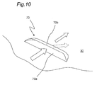
- the cooling air blow-off ports 70 have a plurality of slit parts 70a arranged at specified intervals along the left and right direction and cut and raised parts 70b as cooling air guiding parts that are provided on one (downwind side for the cooling air) of longitudinal edges of the slit parts 70a.
- Longitudinal direction of the slit parts 70a is inclined with respect to the left and right direction along bottom edge of the front face of the casing 1 so as to extend from rear left face side toward front right face side.
- the cut and raised parts 70b of the cooling air blow-off ports 70 are formed by cutting on and raising of the casing 1 toward inside (upside in Fig. 10 ).
- the cut and raised parts 70b are provided as the cooling air guiding parts in the cooling air blow-off ports 70 in the embodiment, whereas the cooling air guiding parts are not limited thereto and flow of the cooling air may be controlled by separate members.
- the portion of the cooling air that flows through between a bottom face of the heating chamber 8 and the bottom plate 30 from the electric component chamber 9 (shown in Fig. 5 ) on right side toward left side where the exhaust duct 100 (shown in Fig. 8 ) exists is blown off through the cooling air blow-off ports 70 toward the region S (shown in Fig. 17 ) facing the discharge ports 104 in the dew receiving container 4 (shown in Figs. 11 , 12) .
- Fig. 11 shows a perspective view of the heating cooker which is shown in Fig. 9 and to which the dew receiving container 4 is attached, as seen looking from the front and diagonally lower side.
- the casing 1, the door 2 with handle, and the operation panel 3 are also mounted thereon.
- Fig. 12 is a left side view of the heating cooker shown in Fig. 11 .
- Fig. 13 shows a top plan view of the exhaust duct 100 of the heating cooker
- Fig. 14 shows a sectional view taken along a line XIV-XIV of Fig. 13
- Fig. 15 shows a bottom view of the exhaust duct 100
- Fig. 16 shows a front view of the exhaust duct 100.
- the exhaust duct 100 has a merging part 100a on which an exhaust inlet 101 and the cooling air inlet 102 (shown in Figs. 14 , 15 ) are provided and a stirring discharge part 100b which extends rightward at a right angle from front face side (lower side in a page of Fig. 12 ) of the merging part 100a.
- a cylindrical connection part 120 having the exhaust inlet 101 is provided on top side of the merging part 100a of the exhaust duct 100 so as to stand thereon.
- a shield wall 103 having a section shaped like a letter U is provided in the exhaust duct 100 so as to surround a columnar region which is defined by extending the connection part 120 into the exhaust duct 100.
- the shield wall 103 opens on the front face side (lower side in the page of Fig. 13 ) thereof.
- the four discharge ports 104 are formed at specified intervals on bottom side of the stirring discharge part 100b of the exhaust duct 100.
- the drain receiving part 111 to which the extremity part of the drain groove 110 is connected is provided on the rear face side (left side in a page of Fig. 14 ) of the merging part 100a of the exhaust duct 100.
- the cooling air inlet 102 is provided on the bottom side (left side in the page of Fig. 14 ) between the drain receiving part 111 and the exhaust inlet 101.
- Grooves 112, 113, and 114 are formed on a right side face of the merging part 100a, a rear face side and a right side face of the stirring discharge part 100b, respectively, on the exhaust duct 100, and a drain port 115 is formed in the groove 114.
- Drain guide grooves are composed of the grooves 112, 113, and 114.
- an opening part 121 is provided between the cooling air inlet 102 and the connection part 120, and an inclined surface 122 that gradually lowers toward the stirring discharge part 100b is provided between the opening part 121 and the merging part 100a.
- an inclined surface 124 is provided that gradually lowers from a side of the merging part 100a toward a right end thereof.
- the condensate water flows in through the exhaust inlet 101, the condensate water can be guided to the stirring discharge part 100b and can be drained through the four discharge ports 104 by the inclined surface 122 in the merging part 100a and the inclined surface 124 in the stirring discharge part 100b.
- a partition wall 123 is provided of which top end is higher than bottom part immediately under the exhaust inlet 101 in the exhaust duct 100.
- Position along height direction of the cooling air inlet 102 into which the cooling air flows from under the exhaust duct 100 is lower than position along the height direction of the discharge ports 104 of the exhaust duct 100, and the position along the height direction of the discharge ports 104 of the exhaust duct 100 is lower than position along the height direction of the exhaust inlet 101 of the exhaust duct 100.
- Difference in height between the cooling air inlet 102 and the discharge ports 104 is designated by H1
- difference in height between the discharge ports 104 and the exhaust inlet 101 is designated by H2.
- the exhaust duct of the heating cooker of the invention is not limited to the exhaust duct 100 of the embodiment, and has only to have an exhaust inlet into which exhaust from the exhaust path flows, an air inflow port into which a portion of air from the fan flows from underside, and discharge ports through which mixture of the exhaust having flowed in through the exhaust inlet and the portion of the air from the fan having flowed in through the air inflow port is discharged to the outside, and position along the height direction of the air inflow port of the exhaust duct has only to be lower than position along the height direction of the discharge ports of the exhaust duct, and the position along the height direction of the air inflow port of the exhaust duct has only to be lower than position along the height direction of the exhaust inlet of the exhaust duct.
- the position along the height direction of the exhaust inlet of the exhaust duct may be lower than the position along the height direction of the discharge ports of the exhaust duct, and the position along the height direction of the air inflow port has only to be the lowest of the positions of the air inflow port, the exhaust inlet, and the discharge ports of the exhaust duct.
- the portion of the cooling air from the cooling fan 16 flows into the cooling air inlet 102 of the exhaust duct 100 from the underside in the embodiment, whereas a fan for discharge, a fan for dilution or the like may be used therefor without limitation to the cooling fan.
- the exhaust flows from inside of the heating chamber 8 (shown in Fig. 6 ) through the exhaust tube 18 (shown in Fig. 6 ) and the exhaust inlet 101 into the merging part 100a of the exhaust duct 100, and the portion of the cooling air that flows through between the bottom face of the heating chamber 8 and the bottom plate 30 from the electric component chamber 9 (shown in Fig. 5 ) on the right side toward the left side where the exhaust duct 100 (shown in Fig. 8 ) exists flows through the cooling air inlet 102 into the merging part 100a of the exhaust duct 100.
- Fig. 17 shows a top plan view of the dew receiving container 4 of the heating cooker
- Fig. 18 shows a perspective view of the dew receiving container 4, as seen looking from rear and diagonally upper side.
- the dew receiving container 4 has a first dew receiving recess 41 in shape of a laterally long rectangle and a second dew receiving recess 42 provided in front of the first dew receiving recess 41, and the first dew receiving recess 41 and the second dew receiving recess 42 are separated by a rib 43 as a cooling air guiding wall provided in the dew receiving container 4.
- the rib 43 includes a first rib 43a and a second rib 43b having a height smaller than the first rib 43a has.
- the first rib 43a occupies two-thirds in general on right side (left side in Fig. 18 ) of the rib 43.
- the rib 43 is provided as the cooling air guiding wall in the dew receiving container 4 in the embodiment, whereas the cooling air guiding part is not limited thereto and the cooling air may be guided by separate members.
- Fitting recesses 45A, 45B that open on the rear face side are provided at both ends of the first dew receiving recess 41 and curved arm parts 46A, 46B that extend toward the rear face side are provided in the fitting recesses 45A, 45B, respectively.
- Guide parts 47A, 47B are provided on sides facing the first dew receiving recess 41 in the fitting recesses 45A, 45B, respectively.
- the exhaust from the discharge ports 104 of the exhaust duct 100 is received by the region S in the second dew receiving recess 42 in the dew receiving container 4 that resides thereunder and is diffused to the outside of the casing 1.
- the exhaust diffuses from inside of the second dew receiving recess 42 in the dew receiving container 4 through a gap between the dew receiving container 4 and the door 2 with handle, a gap between the dew receiving container 4 and the casing 1 and/or the like into vast outside space on the front face side of the casing 1.
- Waterdrops dropping from the drain port 115 of the exhaust duct 100 are received by the second dew receiving recess 42 in the dew receiving container 4.
- the cooling air blown off through the cooling air blow-off ports 70 provided on the bottom part and front face side of the casing 1 is guided toward the region S in the dew receiving container 4 by the rib 43 as the cooling air guiding wall.
- the water supply tank containing a required quantity of water is housed in the tank housing part 15, and cooking with use of steam is thereafter started by an operation on the operation panel 3.
- the heaters 26 provided on the upper side in the heating chamber 8 are turned on, the water supply pump is activated so as to supply water in the water supply tank into the steam producing device 13, and steam is produced by heating of the water supplied into the steam producing device 13 by the steam producing heater 24.
- the steam produced by the steam producing device 13 blows into the heating chamber 8, and becomes superheated steam having a temperature of 100°C or higher by being heated in the heating chamber 8 by the heaters 26.
- oven cooking may be performed with use of only the heaters 26 (shown in Figs. 4 and 5 ) and without use of steam or steam cooking or the like may be performed with use of only steam produced by the steam producing device 13 and without use of the heaters 26.
- Fig. 19 shows a front view of the heating cooker, with the door 2 with handle opened, in cooking with use of microwaves.
- an object to be heated is placed on the bottom part of the heating chamber 8.
- numeral 80 denotes the steam blow-off ports through which steam is blown from the steam producing device 13 (shown in Fig. 5 ) into the heating chamber 8.
- Fig. 20 shows a front view of the heating cooker in cooking of a small piece of food by the heaters 26.
- a tray 32 having a grill 33 placed thereon is inserted into a lower level in the heating chamber 8, and the object 23 to be heated is placed on the grill 33.
- the object 23 to be heated is heated by the heaters 26 placed on the upper side in the heating chamber 8.
- Fig. 21 shows a front view of the heating cooker in cooking of a large piece of food by the heaters 26.
- the tray 32 having the grill 33 placed thereon is placed on the bottom part in the heating chamber 8, and the object 23 to be heated is placed on the grill 33.
- the object 23 to be heated is heated by the heaters 26 placed on the upper side in the heating chamber 8.
- Fig. 22 shows a schematic view for illustrating air flow on the front face side and the lower side of the heating cooker.
- Fig. 22 is the schematic view as seen looking from above, black arrows denoting the cooling air flowing through between the bottom face of the heating chamber 8 and the bottom plate 30 from the electric component chamber 9 (shown in Fig. 5 ) on the right side toward the left side where the exhaust duct 100 (shown in Fig. 8 ) exists, a white arrow defined by solid lines denoting the exhaust from the inside of the heating chamber 8, white arrows defined by dashed lines denoting mixed air.
- the drain port 115 is omitted in Fig. 22 .
- the exhaust flows from the inside of the heating chamber 8 (shown in Fig. 6 ) through the exhaust inlet 101 (shown in Fig. 13 ) of the exhaust duct 100 into the exhaust duct 100, and the portion of the cooling air that flows through between the bottom face of the heating chamber 8 and the bottom plate 30 from the electric component chamber 9 (shown in Fig. 5 ) on the right side toward the left side where the exhaust duct 100 (shown in Fig. 8 ) exists flows through the cooling air inlet 102 (shown in Fig. 13 ) of the exhaust duct 100 into the exhaust duct 100.
- the cooling air and the exhaust are mixed in the exhaust duct 100 and are thereafter discharged through the four discharge ports 104 toward the dew receiving container 4 below.
- the exhaust from the inside of the heating chamber 8 is guided by the exhaust tube 18 and the exhaust duct 100 through the inside of the casing 1 to the front face side.
- the exhaust from the discharge ports 104 of the exhaust duct 100 is received and is diffused to the outside of the casing 1 by the dew receiving container 4 provided on the front face side of the casing 1.
- the highly heated exhaust containing steam from the inside of the heating chamber 8 is cooled by being mixed with the cooling air in the exhaust duct 100, so that the cooled exhaust having a decreased temperature can be received by the dew receiving container 4 on the front face side and can be diffused to the vast outside space on the front face side of the casing 1.
- Means for cooking the object to be heated in the heating chamber 8 is not limited to heating by the heaters and may be cooking including steam cooking with use of steam and the like or may be cooking with use of superheated steam having a temperature of 100°C or higher.
- the position along the height direction of the cooling air inlet 102 into which the cooling air flows from under the exhaust duct 100 is lower than the position along the height direction of the discharge ports 104 of the exhaust duct 100, and the position along the height direction of the cooling air inlet 102 of the exhaust duct 100 is lower than the position along the height direction of the exhaust inlet 101 of the exhaust duct 100, so that the exhaust that flows through the exhaust inlet 101 of the exhaust duct 100 into the exhaust duct 100 when the fan is stopped due to breakdown thereof or the like is prevented from flowing out through the cooling air inlet 102 that is in the lowest position because the exhaust is initially and gradually accumulated from upside in the exhaust duct 100 and is thereafter discharged to the outside through the discharge ports 104 that are in the higher position along the height direction than the cooling air inlet 102. Therefore, the exhaust from the inside of the heating chamber 8 can be prevented from flowing into the main body even if the cooling fan 16 for supplying the cooling air that is to be mixed with the exhaust breaks down.
- the steam can be prevented from flowing into the main
- the shield wall 103 that has the section shaped like a letter U so as to surround a side for the cooling air inlet 102, of the columnar region extended from the exhaust inlet 101 into the exhaust duct 100 and so as to open on a side of the columnar region for the discharge ports 104, the exhaust from the exhaust inlet 101 can be drawn into the exhaust duct 100 by ejector effect owing to difference in flow velocity between flow of the cooling air from the cooling air inlet 102 and the exhaust from the exhaust inlet 101 because the shield wall 103 opens on the side for the discharge ports 104 in the air path from the cooling air inlet 102 to the discharge ports 104.
- the exhaust flowing in through the exhaust inlet 101 can smoothly be merged with the cooling air from the cooling air inlet 102.
- the four discharge ports 104 of the exhaust duct 100 prevent discharge of highly heated exhaust because the exhaust is dispersively discharged to the outside through the plurality of discharge ports 104.
- the number of the discharge ports of the exhaust duct is not limited thereto and may be two, three, or five or more.
- the exhaust that has flowed into the exhaust duct 100 through the exhaust inlet 101 is mixed with the portion of the cooling air from the cooling fan 16 that has flowed in through the cooling air inlet 102 in the air path between the cooling air inlet 102 and the discharge ports 104, and the mixed exhaust is thereafter guided through the bent air path to the discharge ports 104, so that efficient mixture of the exhaust and the cooling air results in uniform temperature of the mixed exhaust that is discharged to the outside through the discharge ports 104 and prevents discharge of highly heated exhaust with biased temperature distribution.
- the partition wall 123 of which the top end is higher than the bottom part immediately under the exhaust inlet 101 in the exhaust duct 100 and which is provided in the air path between the cooling air inlet 102 and the exhaust inlet 101 in the exhaust duct 100 prevents the condensate water from flowing toward the cooling air inlet 102 that is lower in position along the height direction than the exhaust inlet 101.
- the exhaust duct 100 having the drain guide grooves (groove 112, groove 113, and groove 114) that are provided on outside of side walls of the exhaust duct 100 and that guide drain from the side of the exhaust inlet 101 toward the side of the discharge ports 104 and having the drain port 105 that is provided on a side in the drain guide grooves closer to the discharge ports 104, the condensate water produced in the casing 1 is gathered by the drain receiving part 111, and the gathered drain is thereafter guided toward the drain port 105 by the drain guide grooves of the exhaust duct 100 and is discharged through the drain port 105 to the outside.
- the drain guide grooves groove 112, groove 113, and groove 114
- the exhaust duct 100 can be cooled, the temperature of the mixed exhaust in the exhaust duct 100 can be decreased, and effect of cooling the exhaust can be improved.
- the one exhaust duct 100 is capable of combining exhaust disposal function and drain disposal function.
- the mixed exhaust from the discharge ports 104 of the exhaust duct 100 is received and is diffused to the outside of the casing 1 by the dew receiving container 4 that is placed under the opening of the heating chamber 8, and thus the cooled exhaust having a decreased temperature can be received by the dew receiving container 4 on the front face side and can be diffused to the vast outside space on the front face side of the casing 1.
- the portion of the cooling air from the cooling fan 16 for cooling at least the electric components in the casing 1 is blown off through the cooling air blow-off ports 70 provided on the bottom part and the front face side of the casing 1 toward the region in the dew receiving container 4 that receives and diffuses the exhaust from the discharge ports 104 of the exhaust duct 100, and the exhaust blown off from the discharge ports 104 of the exhaust duct 100 into the dew receiving container 4 is thereby diluted with the portion of the cooling air while the diffusion thereof is promoted, so that the exhaust can efficiently be diffused to the vast outside space on the front face side of the casing 1.
- the cooling air blown off through the cooling air blow-off ports 70 provided on the bottom part and the front face side of the casing 1 is guided toward the region S in the dew receiving container 4 that receives and diffuses the exhaust from the discharge ports 104 of the exhaust duct 100, by the cut and raised parts 70b (the cooling air guiding parts) provided in the cooling air blow-off ports 70, and thus the exhaust blown off from the discharge ports 104 of the exhaust duct 100 into the dew receiving container 4 can efficiently be diluted and diffused.
- the dew receiving container 4 receives the exhaust from the discharge ports 104 of the exhaust duct 100, on the side at left side end of the casing 1 where a center of pivoting of the door 2 with handle exists, and thus a hand that grasps the door 2 with handle being opened is opposed to the center of pivoting of the door 2 with handle, so that the hand that grasps the door 2 with handle is prevented from being exposed to the exhaust diffused by the dew receiving container 4.
- the cooling air blown off through the cooling air blow-off ports 70 provided on the bottom part and the front face side of the casing 1 is guided toward the region S in the dew receiving container 4 that receives and diffuses the exhaust from the discharge ports 104 of the exhaust duct 100, by the rib 43 (cooling air guiding wall) that is provided in the dew receiving container 4, and thus the exhaust blown off from the discharge ports 104 of the exhaust duct 100 into the dew receiving container 4 can efficiently be diluted and diffused.
- the exhaust from the inside of the heating chamber 8 is mixed with the other portion of the cooling air from the cooling fan 16 and is discharged into the dew receiving container 4 by the exhaust duct 100 provided on the side of the discharge ports 104 of the exhaust duct 100 in the casing 1, and thus the dilution of the exhaust and the decrease in the temperature of the exhaust can efficiently be attained with the utilization of the cooling air from the cooling fan 16 for cooling the electric components.
- the exhaust tube 18 that is the exhaust path may be extended through the electric component chamber 9 (cooling space) in the casing 1 so as to guide the exhaust from the inside of the heating chamber 8 to the front face side.
- path length of the exhaust path can be increased, and cooling efficiency can be increased by the extension of the path running through the electric component chamber 9 (cooling space).
- the heating cooker using the dew receiving container 4 that diffuses the mixed exhaust from the discharge ports of the exhaust duct has been described for the embodiment, whereas form of the dew receiving container is not limited thereto and the dew receiving container has only to receive the exhaust from the discharge ports of the exhaust duct and to diffuse the exhaust to the outside of the casing.
- the opening 8a of the heating chamber 8 is opened and closed by the door 2 with handle that pivots in transversal directions with respect to the casing 1 in the embodiment, whereas a door which the heating cooker of the invention includes may be of sliding type or turning type.
- Heating cookers according to the invention includes not only microwave ovens using superheated steam but also ovens using superheated steam, microwave ovens not using superheated steam, ovens not using superheated steam, and the like, for instance.
- healthy cooking can be performed by use of superheated steam or saturated steam in microwave ovens and the like.
- superheated steam or saturated steam having a temperature of 100°C or higher is supplied onto surfaces of food, the superheated steam or saturated steam deposited onto the surfaces of the food condenses and gives the food a great quantity of latent heat of condensation, and therefore heat can efficiently be transmitted to the food.
- the condensate water is deposited on the surfaces of the food, and salt content, oil content and the like drop with the condensate water, so that salt content, oil content and the like in the food can be reduced.
- a condition poor in oxygen refers to a condition in which volume percentage of oxygen is 10% or lower (e.g., between 0.5 and 3%) in the heating chamber.
Landscapes
- Physics & Mathematics (AREA)
- Electromagnetism (AREA)
- Engineering & Computer Science (AREA)
- Chemical & Material Sciences (AREA)
- Combustion & Propulsion (AREA)
- Mechanical Engineering (AREA)
- General Engineering & Computer Science (AREA)
- Electric Ovens (AREA)
- Cookers (AREA)
Abstract
Description
- The present invention relates to a heating cooker.
- There has been a conventional heating cooker that performs cooking with use of steam (see
JP 2008-116094 A - In the heating cooker having above configuration, exhaust from inside of a heating chamber is mixed and diluted with indoor air, so that temperature of the exhaust is decreased, and the exhaust is discharged from upper rear face side of a main body thereof toward front face side thereof. On condition that there are wall surfaces in vicinity of the rear face side of the heating cooker main body, shelves just thereover, and/or the like, corrosion, dense growth of mold and/or the like are thereby prevented that might be caused on the wall surfaces, shelves and/or the like by contact therewith of highly heated exhaust containing steam.
- For the heating cooker that performs cooking with use of steam, in particular, there is difficulty in placement in a narrow space of a structure in which exhaust from the chamber is discharged from the rear face side toward the front face side of the main body.
- The applicants have conceived a heating cooker that is capable of mixing in an exhaust duct a portion of air, from a cooling fan for cooling electric components in a main body, with exhaust from inside of a heating chamber and thereafter discharging the mixed exhaust from front face side of the main body. The heating cooker is described in order to facilitate understanding of the invention and is neither publicly known art nor the prior art.
- On condition that the cooling fan breaks down in the heating cooker having a structure of the exhaust duct into which the portion of the air from the cooling fan is taken, however, there is a possibility that the exhaust from the inside of the heating chamber flows into the main body without being discharged to outside.
- PATENT LITERATURE 1:
JP 2008-116094 A - An object of the invention is to provide a heating cooker that prevents exhaust from inside of a heating chamber from flowing into a main body thereof even if a fan for supplying air that is to be mixed with the exhaust breaks down.
- In order to achieve the object, a heating cooker of the invention comprises:
- a casing,
- a heating chamber that is provided in the casing and that has an opening on a front face thereof,
- an exhaust path for guiding exhaust from inside of the heating chamber to front face side of the casing,
- a fan that is provided in the casing, and
- an exhaust duct having an exhaust inlet into which the exhaust from the exhaust path flows, an air inflow port into which a portion of air from the fan flows from underside, and at least one discharge port through which mixture of the exhaust having flowed in through the exhaust inlet and the portion of the air from the fan having flowed in through the air inflow port is discharged to outside,
- wherein position along height direction of the air inflow port of the exhaust duct is lower than position along the height direction of the discharge port of the exhaust duct, and wherein the position along the height direction of the air inflow port of the exhaust duct is lower than position along the height direction of the exhaust inlet of the exhaust duct.
- In above configuration, the highly heated exhaust containing steam from the inside of the heating chamber is guided by the exhaust path to the front face side of the casing and flows through the exhaust path and the exhaust inlet into the exhaust duct when cooking is performed. The exhaust that has flowed into the exhaust duct is mixed with the portion of the air from the fan that has flowed in through the air inflow port and is forced to be discharged to the outside through the discharge port by wind pressure of the air from the fan. Thus the mixed exhaust mixed in the exhaust duct can be discharged from the front face side of a main body thereof. The position along the height direction of the air inflow port into which the air flows from under the exhaust duct is lower than the position along the height direction of the discharge port of the exhaust duct, and the position along the height direction of the air inflow port of the exhaust duct is lower than the position along the height direction of the exhaust inlet of the exhaust duct, so that the exhaust that flows through the exhaust inlet of the exhaust duct into the exhaust duct when the fan is stopped due to breakdown or the like is prevented from flowing out through the air inflow port that is in the lowest position because the exhaust is initially and gradually accumulated from upside in the exhaust duct and is thereafter discharged to the outside through the discharge port that is in the higher position along the height direction than the air inflow port. Accordingly, the exhaust from the inside of the heating chamber can be prevented from flowing into the casing even if the fan for supplying air that is to be mixed with the exhaust breaks down.
- In the heating cooker in accordance with an embodiment,
the exhaust inlet is provided in an air path between the air inflow port and the discharge port in the exhaust duct, and wherein
a shield wall is provided between the air inflow port and the exhaust inlet in the exhaust duct. - In the embodiment, flow of the exhaust that has flowed in from the inside of the heating chamber through the exhaust path and the exhaust inlet can be prevented from being disturbed by the air that has flowed in from the air inflow port and from being reversed toward the exhaust inlet, by the provision of the exhaust inlet in the air path between the air inflow port and the discharge port in the exhaust duct and the provision of the shield wall between the air inflow port and the exhaust inlet.
- In the heating cooker in accordance with an embodiment,
the shield wall is a wall that has a section shaped like a letter U so as to surround a side for the air inflow port, of a columnar region extended from the exhaust inlet into the exhaust duct and so as to open on a side of the columnar region for the discharge port. - In the embodiment, the exhaust from the exhaust inlet can be drawn into the exhaust duct by ejector effect owing to difference in flow velocity between flow of the air from the air inflow port and the exhaust from the exhaust inlet, because the shield wall opens on the side for the discharge port in the air path from the air inflow port to the discharge port, with use of the shield wall that has the section shaped like a letter U so as to surround the side for the air inflow port, of the columnar region extended from the exhaust inlet into the exhaust duct and so as to open on the side of the columnar region for the discharge port. Thus the exhaust flowing in through the exhaust inlet can smoothly be merged with the air from the air inflow port.
- In the heating cooker in accordance with an embodiment,
the exhaust duct comprises a plurality of the discharge ports. - Even if quantity of the exhaust is sharply increased according to types of objects to be heated in the heating chamber and/or the like, in the embodiment, discharge of highly heated exhaust can be prevented by the plurality of discharge ports of the exhaust duct because the exhaust is dispersively discharged to the outside through the plurality of discharge ports.
- In the heating cooker in accordance with an embodiment,
the air inflow port is placed in a region except a region immediately under the exhaust inlet in the exhaust duct. - Even if condensate water produced in the exhaust path and/or the like drops from the exhaust inlet of the exhaust duct when the exhaust from the inside of the heating chamber flows through the exhaust path into the exhaust duct, in the embodiment, the placement of the air inflow port in the region except the region immediately under the exhaust inlet in the exhaust duct prevents leakage of the water through the air inflow port that is lower in position along the height direction than the exhaust inlet.
- In the heating cooker in accordance with an embodiment,
the exhaust duct is bent between the air inflow port and the discharge ports and on a position that is nearer to the discharge ports than to the exhaust inlet. - In the embodiment, the exhaust duct is bent between the air inflow port and the discharge ports and on the side of the exhaust inlet that is nearer to the discharge ports in the exhaust duct, the exhaust that has flowed through the exhaust inlet into the exhaust duct is mixed with the portion of the air from the fan that has flowed in through the air inflow port, in the air path between the air inflow port and the discharge ports, and the mixed exhaust is thereafter turned and guided to the discharge ports. Thus efficient mixture of the exhaust and the air results in uniform temperature of the mixed exhaust that is discharged to the outside through the discharge ports and prevents discharge of highly heated exhaust with biased temperature distribution.
- In the heating cooker in accordance with an embodiment,
bottom part in the exhaust duct has an inclined surface that gradually lowers from side of the exhaust inlet toward side of the discharge ports. - Even if condensate water produced in the exhaust path and/or the like drops from the exhaust inlet of the exhaust duct when the exhaust from the inside of the heating chamber flows through the exhaust path into the exhaust duct, in the embodiment, the bottom part of the exhaust duct having the inclined surface that gradually lowers from the side of the exhaust inlet toward the side of the discharge ports causes the condensate water to flow from the side of the exhaust inlet toward the side of the discharge ports along the inclined surface on the bottom part of the exhaust duct and to be discharged to the outside through the discharge ports and prevents the condensate water from being accumulated in the exhaust duct.
- In the heating cooker in accordance with an embodiment,
a partition wall of which top end is higher than the bottom part immediately under the exhaust inlet in the exhaust duct is provided in an air path between the air inflow port and the exhaust inlet in the exhaust duct. - Even if condensate water produced in the exhaust path and/or the like drops from the exhaust inlet of the exhaust duct when the exhaust from the inside of the heating chamber flows through the exhaust path into the exhaust duct, in the embodiment, the partition wall of which the top end is higher than the bottom part immediately under the exhaust inlet in the exhaust duct and which is provided in the air path between the air inflow port and the exhaust inlet in the exhaust duct prevents the condensate water from flowing toward the air inflow port that is lower in position along the height direction than the exhaust inlet.
- In the heating cooker in accordance with an embodiment,
the exhaust duct comprises drain guide grooves that are provided on outside of side walls of the exhaust duct and that guide drain from the side of the exhaust inlet toward the side of the discharge ports and a drain port that is provided on a side nearer to the discharge ports than to the exhaust inlet in the drain guide grooves. - According to the embodiment, because of using the exhaust duct having the drain guide grooves that are provided on the outside of the side walls of the exhaust duct and that guides drain from the side of the exhaust inlet toward the side of the discharge ports and the drain port that is provided on the side nearer to the discharge ports than to the exhaust inlet in the drain guide grooves, condensate water produced in the casing and/or the like, for instance, is received and gathered, and the gathered drain is thereafter guided toward the drain port by the drain guide grooves of the exhaust duct and is discharged through the drain port to the outside. By the condensate water flowing in the drain guide grooves on the side walls of the exhaust duct, in this manner, the exhaust duct can be cooled, temperature of the mixed exhaust in the exhaust duct can be decreased, and effect of cooling the exhaust can be improved. In addition, the one exhaust duct is capable of combining exhaust disposal function and drain disposal function.
- The heating cooker in accordance with an embodiment comprises
a dew receiving container that is placed under the opening of the heating chamber, that receives the exhaust from the discharge ports of the exhaust duct, and that diffuses the exhaust to outside of the casing. - According to the embodiment, because the mixed exhaust from the discharge ports of the exhaust duct is received and is diffused to the outside of the casing by the dew receiving container that is placed under the opening of the heating chamber, the mixed exhaust having a decreased temperature by being cooled can be received by the dew receiving container on the front face side and can be diffused to vast outside space on the front face side of the casing.
- According to the heating cooker of the invention, as apparent from the above, the heating cooker can be provided that prevents the exhaust from the inside of the heating chamber from flowing into the main body thereof even if the fan for supplying the air that is to be mixed with the exhaust breaks down.
-
-
Fig. 1 is a front view of a heating cooker in accordance with an embodiment of the invention; -
Fig. 2 is a front view of the heating cooker having a door with handle fully opened; -
Fig. 3 is a top plan view of the heating cooker having the door with handle fully opened; -
Fig. 4 is a schematic section of the heating cooker; -
Fig. 5 is a perspective view of the heating cooker from which a casing has been removed, as seen looking from rear and diagonally upper side; -
Fig. 6 is a perspective view of the heating cooker from which the casing has been removed, as seen looking from front and diagonally upper side; -
Fig. 7 is a left side view of the heating cooker from which the casing has been removed; -
Fig. 8 is a perspective view of the heating cooker from which the casing and a bottom plate have been removed, as seen looking from front and diagonally lower side; -
Fig. 9 is a perspective view of the heating cooker which is shown inFig. 8 and on which the bottom plate is mounted, as seen looking from the front and diagonally lower side; -
Fig. 10 is a perspective view of a cooling air blow-off port having a slit part and a raised part, as seen looking from rear and diagonally upper side; -
Fig. 11 is a perspective view of the heating cooker which is shown inFig. 9 and to which a dew receiving container is attached, as seen looking from the front and diagonally lower side; -
Fig. 12 is a left side view of the heating cooker; -
Fig. 13 is a top plan view of an exhaust duct of the heating cooker; -
Fig. 14 is a sectional view taken along a line XIV-XIV ofFig. 13 ; -
Fig. 15 is a bottom plan view of the exhaust duct; -
Fig. 16 is a front view of the exhaust duct; -
Fig. 17 is a top plan view of the dew receiving container of the heating cooker; -
Fig. 18 is a perspective view of the dew receiving container, as seen looking from rear and diagonally upper side; -
Fig. 19 is a front view of the heating cooker with the door with handle opened in cooking with use of microwaves. -
Fig. 20 is a front view of the heating cooker in cooking of a small piece of food by heaters; -
Fig. 21 is a front view of the heating cooker in cooking of a large piece of food by the heaters; and -
Fig. 22 is a schematic representation for illustrating air flow on front face side and lower side in the heating cooker. - Hereinbelow, a heating cooker of the invention will be described in detail with reference to an embodiment shown in the drawings.
-
Fig. 1 is a front view of the heating cooker in accordance with the embodiment of the invention. - As shown in
Fig. 1 , the heating cooker has acasing 1 and adoor 2 with a handle, as an example of a door that is mounted on front face side of thecasing 1. Heatresistant glass 5 is mounted at general center of thedoor 2 with handle. Anoperation panel 3 is provided on the front face side of thecasing 1 so as to adjoin thedoor 2 with handle that is closed. Adew receiving container 4 as an example of an exhaust receiving part is provided under thedoor 2 with handle and theoperation panel 3. - A plurality of push buttons and the like are mounted on the
operation panel 3. Theoperation panel 3 has a liquidcrystal display part 7, which provides a display according to an operation. - The
dew receiving container 4 is a container that is attachable to and detachable from twofront legs casing 1. Once thedew receiving container 4 is inserted to underside of thecasing 1 from the front side toward rear side and is mounted on thefront legs dew receiving container 4 is positioned under a rear face (back face) of thedoor 2 with handle that is closed. Thus condensate water deposited on the rear face of thedoor 2 with handle drops into thedew receiving container 4 placed under anopening 8a (shown inFig. 8 ) of the heating chamber 8 (shown inFig. 8 ) when thedoor 2 with handle is opened. -
Fig. 2 shows a front view of the heating cooker with thedoor 2 with handle fully opened, as seen looking from the front face side, andFig. 3 shows a top plan view of the heating cooker. InFigs. 2 and3 , the same components as those of the heating cooker shown inFig. 1 are provided with the same reference numerals. - As shown in
Figs. 2 and3 , theheating chamber 8 for heating an object 23 (seeFig. 4 ) to be heated is provided in thecasing 1. Thedoor 2 with handle that is provided on the front face side of thecasing 1 pivots in left and right directions on left side end part of thecasing 1 and opens and closes theopening 8a (shown inFig. 8 ) on the front face of the heating chamber 8 (shown inFig. 4 ). Thedoor 2 with handle is pivotably mounted through hinges (not shown) on a side part of thecasing 1 that is opposed to theoperation panel 3. - Latch hooks 90, 90 are provided on right side and on the rear face of the
door 2 with handle. When thedoor 2 with handle is closed, the latch hooks 90, 90 are inserted into insertion holes 91, 91 provided on periphery of theopening 8a and are releasably engaged with latch mechanisms (not shown) in thecasing 1. The engagement of the latch hooks 90, 90 can be released by a grasp by a user on ahandle 2a of thedoor 2 with handle. - In
Fig. 2 , numeral 80 denotes steam blow-off ports through which steam produced by a steam producing device 13 (shown inFig. 5 ) is blown into theheating chamber 8. -
Fig. 4 shows a schematic section of the heating cooker. InFig. 4 , numeral 26 denotes heaters placed on upper side in theheating chamber 8. - In the heating cooker, as shown in
Fig. 4 , a portion of air taken in by a coolingfan 16 from outside through anair intake 17 passes through anelectric component chamber 9 as an example of a cooling space and thereafter flows into theheating chamber 8 through anair supply port 8b that is in open state with opening of anair supply damper 50. On the other hand, the other portion of the air taken in from the outside passes through theelectric component chamber 9, thereafter flows to bottom part side of thecasing 1, and then flows through an air path under theheating chamber 8 into a coolingair inlet 102 as an example of an air inflow port of anexhaust duct 100. - The portion of the air in the
heating chamber 8 is discharged into theexhaust duct 100 through anexhaust port 8c and anexhaust tube 18 as an example of an exhaust path and is mixed with air having flowed in through anexhaust inlet 101, in theexhaust duct 100. Then the exhaust diluted in theexhaust duct 100 is blown downward through fourdischarge ports 104 into thedew receiving container 4. - The portion of the air that flows to the bottom part side of the
casing 1 and that then flows through the air path under theheating chamber 8 is blown through a plurality of cooling air blow-offports 70, provided on the front face side on a bottom plate 30 (shown inFig. 9 ) of thecasing 1, toward a region S (Fig. 17 ) in thedew receiving container 4 that receives and diffuses the exhaust from thedischarge ports 104. -
Fig. 5 shows a perspective view of the heating cooker from which thecasing 1 has been removed, as seen looking from rear and diagonally upper side. - As shown in
Fig. 5 , theheating chamber 8 for heating the object 23 (shown inFig. 4 ) to be heated is provided in thecasing 1. In thecasing 1, theelectric component chamber 9 as the example of the cooling space is provided on a lateral side of theheating chamber 8 and on the rear side of theoperation panel 3, and anair intake space 10 is provided on the rear side of theheating chamber 8 and on the rear side of theelectric component chamber 9. -
Heat shield plates heating chamber 8, respectively. That is, theheat shield plates heating chamber 8 except for theopening 8a. Spaces between theheat shield plates 11 and theheating chamber 8 are filled with heat insulating material (not shown). - The
steam producing device 3 for producing steam that is supplied into theheating chamber 8 is provided on the rear face side of theheating chamber 8, and a water supply pump (not shown) connected to thesteam producing device 13 through a water supply tube is provided under theheating chamber 8. Atank housing part 15 in which a water supply tank (not shown) is housed, amagnetron 51, apower supply transformer 52 and the like are provided in theelectric component chamber 9 in thecasing 1. When theobject 23 to be heated is heated, the cooling air from the coolingfan 16 flows through theelectric component chamber 9 so that electric components such as themagnetron 51 can be cooled. - With drive of the cooling
fan 16, air outside thecasing 1 flows through a plurality of air intakes (not shown) into theair intake space 10. The air in theair intake space 10 is delivered into theelectric component chamber 9 by the coolingfan 16. The air intakes are each composed of a plurality of slits provided in rear part of thecasing 1. - In
Fig. 5 , numeral 21 denotes a partition wall that serves as a partition between theelectric component chamber 9 and theair intake space 10. The coolingfan 16 is mounted on thepartition wall 21. Theheaters 26 are provided on the upper side in theheating chamber 8. Microwaves produced by themagnetron 51 are guided through a waveguide (not shown) to center of lower part in theheating chamber 8, are radiated toward upside in theheating chamber 8 while being stirred by a rotating antenna (not shown), and thereby heat the object 23 (shown inFig. 4 ) to be heated. - Water in the water supply tank housed in the
housing part 15 is supplied through the water supply tube (not shown) to thesteam producing device 13 by drive of the water supply pump. Thesteam producing device 13 heats the water from the water supply pump by asteam producing heater 24 and thereby produces steam. -
Fig. 6 shows a perspective view of the heating cooker from which thecasing 1 has been removed, as seen looking from front and diagonally upper side, andFig. 7 shows a left side view of the heating cooker from which thecasing 1 has been removed. As shown inFigs. 6 and7 , an upstream end of theexhaust tube 18 is connected to theexhaust port 8c (shown inFig. 4 ) provided on a left side wall of theheating chamber 8, and a downstream end (exhaust outlet) of theexhaust tube 18 is connected to theexhaust duct 100 made of synthetic resin and provided on lower left side and the front face side in thecasing 1. Theexhaust tube 18 is made of synthetic resin having flexibility. - Gas in the
heating chamber 8 is guided from a side part to the front face side of thecasing 1 by theexhaust tube 18 and theexhaust duct 100 and is then discharged to the outside of thecasing 1. - An extremity part of a
drain groove 110 is connected to adrain receiving part 111 on the rear face side of theexhaust duct 100. Thedrain groove 110 receives condensate water dropping along side faces of theheat shield plates 11 that cover theheating chamber 8. Thedrain groove 110 is omitted inFig. 7 . -
Fig. 8 shows a perspective view of the heating cooker from which thecasing 1 and the bottom plate 30 (shown inFig. 9 ) have been removed, as seen looking from front and diagonally lower side, and theexhaust duct 100 shaped like a letter L is placed on a corner part on front left and lower side of thecasing 1. The coolingair inlet 102 is provided on the rear face side and lower side of theexhaust duct 100 so that opening thereof faces downward, the fourdischarge ports 104 are provided at specified intervals along left and right direction on the front face side and the lower side of theexhaust duct 100, and adrain port 105 is provided at right of thedischarge ports 104. -
Fig. 9 shows a perspective view of the heating cooker which is shown inFig. 8 and on which thebottom plate 30 is mounted, as seen looking from the front and diagonally lower side. As shown inFig. 9 , fivecircular holes 60 corresponding to the fourdischarge ports 104 and to thedrain port 105 on the front face side and the lower side of the exhaust duct 100 (shown inFig. 8 ) are provided on the front face side of thebottom plate 30 of thecasing 1. - Provided on the front face side on the
bottom plate 30 of thecasing 1 and on the rear face side of thecircular holes 60 are the plurality of cooling air blow-offports 70 through which a portion of the cooling air from the cooling fan 16 (shown inFig. 5 ) is blown off toward the region S (shown inFig. 17 ) in the dew receiving container 4 (shown inFigs. 11 ,12 ) that receives and diffuses the exhaust from thedischarge ports 104. - As shown in
Fig. 10 , the cooling air blow-offports 70 have a plurality ofslit parts 70a arranged at specified intervals along the left and right direction and cut and raisedparts 70b as cooling air guiding parts that are provided on one (downwind side for the cooling air) of longitudinal edges of theslit parts 70a. Longitudinal direction of theslit parts 70a is inclined with respect to the left and right direction along bottom edge of the front face of thecasing 1 so as to extend from rear left face side toward front right face side. The cut and raisedparts 70b of the cooling air blow-offports 70 are formed by cutting on and raising of thecasing 1 toward inside (upside inFig. 10 ). - The cut and raised
parts 70b are provided as the cooling air guiding parts in the cooling air blow-offports 70 in the embodiment, whereas the cooling air guiding parts are not limited thereto and flow of the cooling air may be controlled by separate members. - By the cut and raised
parts 70b of the cooling air blow-offports 70, the portion of the cooling air that flows through between a bottom face of theheating chamber 8 and thebottom plate 30 from the electric component chamber 9 (shown inFig. 5 ) on right side toward left side where the exhaust duct 100 (shown inFig. 8 ) exists is blown off through the cooling air blow-offports 70 toward the region S (shown inFig. 17 ) facing thedischarge ports 104 in the dew receiving container 4 (shown inFigs. 11 ,12) . -
Fig. 11 shows a perspective view of the heating cooker which is shown inFig. 9 and to which thedew receiving container 4 is attached, as seen looking from the front and diagonally lower side. InFig. 11 , thecasing 1, thedoor 2 with handle, and theoperation panel 3 are also mounted thereon. -
Fig. 12 is a left side view of the heating cooker shown inFig. 11 . -
Fig. 13 shows a top plan view of theexhaust duct 100 of the heating cooker,Fig. 14 shows a sectional view taken along a line XIV-XIV ofFig. 13 ,Fig. 15 shows a bottom view of theexhaust duct 100, andFig. 16 shows a front view of theexhaust duct 100. - As shown in
Fig. 13 , theexhaust duct 100 has a mergingpart 100a on which anexhaust inlet 101 and the cooling air inlet 102 (shown inFigs. 14 ,15 ) are provided and a stirringdischarge part 100b which extends rightward at a right angle from front face side (lower side in a page ofFig. 12 ) of the mergingpart 100a. Acylindrical connection part 120 having theexhaust inlet 101 is provided on top side of the mergingpart 100a of theexhaust duct 100 so as to stand thereon. Ashield wall 103 having a section shaped like a letter U is provided in theexhaust duct 100 so as to surround a columnar region which is defined by extending theconnection part 120 into theexhaust duct 100. Theshield wall 103 opens on the front face side (lower side in the page ofFig. 13 ) thereof. - The four
discharge ports 104 are formed at specified intervals on bottom side of the stirringdischarge part 100b of theexhaust duct 100. - The
drain receiving part 111 to which the extremity part of thedrain groove 110 is connected is provided on the rear face side (left side in a page ofFig. 14 ) of the mergingpart 100a of theexhaust duct 100. The coolingair inlet 102 is provided on the bottom side (left side in the page ofFig. 14 ) between thedrain receiving part 111 and theexhaust inlet 101.Grooves part 100a, a rear face side and a right side face of the stirringdischarge part 100b, respectively, on theexhaust duct 100, and adrain port 115 is formed in thegroove 114. Water received by thedrain receiving part 111 is guided to thedrain port 115 by thegrooves drain port 115 into thedew receiving container 4 on underside (dashed arrows inFigs. 13 and14 designate flow of the drainage). Drain guide grooves are composed of thegrooves - In the merging
part 100a of theexhaust duct 100, as shown inFig. 14 , anopening part 121 is provided between the coolingair inlet 102 and theconnection part 120, and aninclined surface 122 that gradually lowers toward the stirringdischarge part 100b is provided between the openingpart 121 and the mergingpart 100a. In bottom part in the stirringdischarge part 100b also, an inclined surface 124 (shown inFig. 16 ) is provided that gradually lowers from a side of the mergingpart 100a toward a right end thereof. In event that the condensate water flows in through theexhaust inlet 101, the condensate water can be guided to the stirringdischarge part 100b and can be drained through the fourdischarge ports 104 by theinclined surface 122 in the mergingpart 100a and theinclined surface 124 in the stirringdischarge part 100b. - Under the
opening part 121 between the coolingair inlet 102 and theconnection part 120 of theexhaust duct 100, apartition wall 123 is provided of which top end is higher than bottom part immediately under theexhaust inlet 101 in theexhaust duct 100. - Position along height direction of the cooling
air inlet 102 into which the cooling air flows from under theexhaust duct 100 is lower than position along the height direction of thedischarge ports 104 of theexhaust duct 100, and the position along the height direction of thedischarge ports 104 of theexhaust duct 100 is lower than position along the height direction of theexhaust inlet 101 of theexhaust duct 100. Difference in height between the coolingair inlet 102 and thedischarge ports 104 is designated by H1, and difference in height between thedischarge ports 104 and theexhaust inlet 101 is designated by H2. - The exhaust duct of the heating cooker of the invention is not limited to the
exhaust duct 100 of the embodiment, and has only to have an exhaust inlet into which exhaust from the exhaust path flows, an air inflow port into which a portion of air from the fan flows from underside, and discharge ports through which mixture of the exhaust having flowed in through the exhaust inlet and the portion of the air from the fan having flowed in through the air inflow port is discharged to the outside, and position along the height direction of the air inflow port of the exhaust duct has only to be lower than position along the height direction of the discharge ports of the exhaust duct, and the position along the height direction of the air inflow port of the exhaust duct has only to be lower than position along the height direction of the exhaust inlet of the exhaust duct. Therefore, the position along the height direction of the exhaust inlet of the exhaust duct may be lower than the position along the height direction of the discharge ports of the exhaust duct, and the position along the height direction of the air inflow port has only to be the lowest of the positions of the air inflow port, the exhaust inlet, and the discharge ports of the exhaust duct. - The portion of the cooling air from the cooling
fan 16 flows into the coolingair inlet 102 of theexhaust duct 100 from the underside in the embodiment, whereas a fan for discharge, a fan for dilution or the like may be used therefor without limitation to the cooling fan. - In the
exhaust duct 100 shown inFigs. 13 through 16 , the exhaust flows from inside of the heating chamber 8 (shown inFig. 6 ) through the exhaust tube 18 (shown inFig. 6 ) and theexhaust inlet 101 into the mergingpart 100a of theexhaust duct 100, and the portion of the cooling air that flows through between the bottom face of theheating chamber 8 and thebottom plate 30 from the electric component chamber 9 (shown inFig. 5 ) on the right side toward the left side where the exhaust duct 100 (shown inFig. 8 ) exists flows through the coolingair inlet 102 into the mergingpart 100a of theexhaust duct 100. Then the cooling air and the exhaust flow to the stirringdischarge part 100b while being mixed on downstream side (lower side in a page ofFig. 13 ) of theshield wall 103 in the mergingpart 100a of theexhaust duct 100, are stirred and diluted in the stirringdischarge part 100b, and are thereafter discharged in form of mixed exhaust through the fourdischarge ports 104 into thedew receiving container 4 below. -
Fig. 17 shows a top plan view of thedew receiving container 4 of the heating cooker, andFig. 18 shows a perspective view of thedew receiving container 4, as seen looking from rear and diagonally upper side. - As shown in
Figs. 17 and18 , thedew receiving container 4 has a firstdew receiving recess 41 in shape of a laterally long rectangle and a seconddew receiving recess 42 provided in front of the firstdew receiving recess 41, and the firstdew receiving recess 41 and the seconddew receiving recess 42 are separated by arib 43 as a cooling air guiding wall provided in thedew receiving container 4. Therib 43 includes afirst rib 43a and asecond rib 43b having a height smaller than thefirst rib 43a has. Thefirst rib 43a occupies two-thirds in general on right side (left side inFig. 18 ) of therib 43. - The
rib 43 is provided as the cooling air guiding wall in thedew receiving container 4 in the embodiment, whereas the cooling air guiding part is not limited thereto and the cooling air may be guided by separate members. - Fitting recesses 45A, 45B that open on the rear face side (upper side in
Fig. 17 ) are provided at both ends of the firstdew receiving recess 41 andcurved arm parts fitting recesses Guide parts dew receiving recess 41 in thefitting recesses - When the
dew receiving container 4 is attached to the twofront legs 6, 6 (shown inFig. 1 ) provided on the front side on the bottom part of thecasing 1, fitting protruding parts (not shown) of thefront legs fitting recesses guide parts dew receiving container 4. Then thecurved arm parts dew receiving container 4 undergo elastic deformation and thereby cooperate with theguide parts front legs dew receiving container 4 is held by thefront legs - The region S (shown in
Fig. 17 ) on left side in the seconddew receiving recess 42 of thedew receiving container 4 faces openings of thedischarge ports 104 of the exhaust duct 100 (shown inFigs. 13 through 16 ) that reside thereover. The exhaust from thedischarge ports 104 of theexhaust duct 100 is received by the region S in the seconddew receiving recess 42 in thedew receiving container 4 that resides thereunder and is diffused to the outside of thecasing 1. Then the exhaust diffuses from inside of the seconddew receiving recess 42 in thedew receiving container 4 through a gap between thedew receiving container 4 and thedoor 2 with handle, a gap between thedew receiving container 4 and thecasing 1 and/or the like into vast outside space on the front face side of thecasing 1. - Waterdrops dropping from the
drain port 115 of theexhaust duct 100 are received by the seconddew receiving recess 42 in thedew receiving container 4. - The cooling air blown off through the cooling air blow-off
ports 70 provided on the bottom part and front face side of thecasing 1 is guided toward the region S in thedew receiving container 4 by therib 43 as the cooling air guiding wall. - In the heating cooker having above configuration, the water supply tank containing a required quantity of water is housed in the
tank housing part 15, and cooking with use of steam is thereafter started by an operation on theoperation panel 3. Then theheaters 26 provided on the upper side in theheating chamber 8 are turned on, the water supply pump is activated so as to supply water in the water supply tank into thesteam producing device 13, and steam is produced by heating of the water supplied into thesteam producing device 13 by thesteam producing heater 24. The steam produced by thesteam producing device 13 blows into theheating chamber 8, and becomes superheated steam having a temperature of 100°C or higher by being heated in theheating chamber 8 by theheaters 26. Thus food in theheating chamber 8 is cooked by radiant heat from theheaters 26 on the upper side in theheating chamber 8 and the superheated steam having the temperature of 100°C or higher. Then the superheated steam supplied to and deposited on surfaces of the food condenses on the surfaces of the food and gives the food a great quantity of latent heat of condensation, and therefore heat can efficiently be transmitted to the food. - In the heating cooker, oven cooking may be performed with use of only the heaters 26 (shown in
Figs. 4 and5 ) and without use of steam or steam cooking or the like may be performed with use of only steam produced by thesteam producing device 13 and without use of theheaters 26. -
Fig. 19 shows a front view of the heating cooker, with thedoor 2 with handle opened, in cooking with use of microwaves. In the cooking with use of microwaves, an object to be heated is placed on the bottom part of theheating chamber 8. InFig. 19 , numeral 80 denotes the steam blow-off ports through which steam is blown from the steam producing device 13 (shown inFig. 5 ) into theheating chamber 8. -
Fig. 20 shows a front view of the heating cooker in cooking of a small piece of food by theheaters 26. In the cooking by the heaters 26 (shown inFigs. 4 ,5 ), atray 32 having agrill 33 placed thereon is inserted into a lower level in theheating chamber 8, and theobject 23 to be heated is placed on thegrill 33. Thus theobject 23 to be heated is heated by theheaters 26 placed on the upper side in theheating chamber 8. -
Fig. 21 shows a front view of the heating cooker in cooking of a large piece of food by theheaters 26. In the cooking by the heaters 26 (shown inFigs. 4 ,5 ), thetray 32 having thegrill 33 placed thereon is placed on the bottom part in theheating chamber 8, and theobject 23 to be heated is placed on thegrill 33. Thus theobject 23 to be heated is heated by theheaters 26 placed on the upper side in theheating chamber 8. -
Fig. 22 shows a schematic view for illustrating air flow on the front face side and the lower side of the heating cooker.Fig. 22 is the schematic view as seen looking from above, black arrows denoting the cooling air flowing through between the bottom face of theheating chamber 8 and thebottom plate 30 from the electric component chamber 9 (shown inFig. 5 ) on the right side toward the left side where the exhaust duct 100 (shown inFig. 8 ) exists, a white arrow defined by solid lines denoting the exhaust from the inside of theheating chamber 8, white arrows defined by dashed lines denoting mixed air. Thedrain port 115 is omitted inFig. 22 . - As shown in
Fig. 22 , the exhaust flows from the inside of the heating chamber 8 (shown inFig. 6 ) through the exhaust inlet 101 (shown inFig. 13 ) of theexhaust duct 100 into theexhaust duct 100, and the portion of the cooling air that flows through between the bottom face of theheating chamber 8 and thebottom plate 30 from the electric component chamber 9 (shown inFig. 5 ) on the right side toward the left side where the exhaust duct 100 (shown inFig. 8 ) exists flows through the cooling air inlet 102 (shown inFig. 13 ) of theexhaust duct 100 into theexhaust duct 100. The cooling air and the exhaust are mixed in theexhaust duct 100 and are thereafter discharged through the fourdischarge ports 104 toward thedew receiving container 4 below. - When the
heating chamber 8 is increased in temperature and is filled with steam, smoke and/or the like produced from heated food in the cooking of the food put in theheating chamber 8, in the heating cooker having the above configuration, the exhaust from the inside of theheating chamber 8 is guided by theexhaust tube 18 and theexhaust duct 100 through the inside of thecasing 1 to the front face side. The exhaust from thedischarge ports 104 of theexhaust duct 100 is received and is diffused to the outside of thecasing 1 by thedew receiving container 4 provided on the front face side of thecasing 1. Then the highly heated exhaust containing steam from the inside of theheating chamber 8 is cooled by being mixed with the cooling air in theexhaust duct 100, so that the cooled exhaust having a decreased temperature can be received by thedew receiving container 4 on the front face side and can be diffused to the vast outside space on the front face side of thecasing 1. - Even if there are wall surfaces in vicinity of the rear face side of the heating cooker main body, shelves just thereover, and/or the like, corrosion, dense growth of mold and/or the like are thereby prevented that might be caused on the wall surfaces, the shelves and/or the like by contact therewith of the highly heated exhaust containing steam, because the exhaust in the chamber is not discharged from the rear face side of the main body. Under condition of the placement in a narrow space, accordingly, the exhaust from the inside of the
heating chamber 8 can be processed without being discharged from the rear face side. - Means for cooking the object to be heated in the
heating chamber 8 is not limited to heating by the heaters and may be cooking including steam cooking with use of steam and the like or may be cooking with use of superheated steam having a temperature of 100°C or higher. - As shown in
Fig. 14 , the position along the height direction of the coolingair inlet 102 into which the cooling air flows from under theexhaust duct 100 is lower than the position along the height direction of thedischarge ports 104 of theexhaust duct 100, and the position along the height direction of the coolingair inlet 102 of theexhaust duct 100 is lower than the position along the height direction of theexhaust inlet 101 of theexhaust duct 100, so that the exhaust that flows through theexhaust inlet 101 of theexhaust duct 100 into theexhaust duct 100 when the fan is stopped due to breakdown thereof or the like is prevented from flowing out through the coolingair inlet 102 that is in the lowest position because the exhaust is initially and gradually accumulated from upside in theexhaust duct 100 and is thereafter discharged to the outside through thedischarge ports 104 that are in the higher position along the height direction than the coolingair inlet 102. Therefore, the exhaust from the inside of theheating chamber 8 can be prevented from flowing into the main body even if the coolingfan 16 for supplying the cooling air that is to be mixed with the exhaust breaks down. Thus the steam can be prevented from entering theelectric component chamber 9. - With the provision of the
exhaust inlet 101 in an air path between the coolingair inlet 102 and thedischarge ports 104 in theexhaust duct 100 and the provision of theshield wall 103 between the coolingair inlet 102 and theexhaust inlet 101, flow of the exhaust that has flowed in from theheating chamber 8 through theexhaust tube 18 and theexhaust inlet 101 can be prevented from being disturbed by the cooling air from the coolingair inlet 102 and from being reversed toward theexhaust inlet 101. - With use of the
shield wall 103 that has the section shaped like a letter U so as to surround a side for the coolingair inlet 102, of the columnar region extended from theexhaust inlet 101 into theexhaust duct 100 and so as to open on a side of the columnar region for thedischarge ports 104, the exhaust from theexhaust inlet 101 can be drawn into theexhaust duct 100 by ejector effect owing to difference in flow velocity between flow of the cooling air from the coolingair inlet 102 and the exhaust from theexhaust inlet 101 because theshield wall 103 opens on the side for thedischarge ports 104 in the air path from the coolingair inlet 102 to thedischarge ports 104. Thus the exhaust flowing in through theexhaust inlet 101 can smoothly be merged with the cooling air from the coolingair inlet 102. - Even if quantity of the exhaust is sharply increased according to type of the
object 23 to be heated in theheating chamber 8 and/or the like, the fourdischarge ports 104 of theexhaust duct 100 prevent discharge of highly heated exhaust because the exhaust is dispersively discharged to the outside through the plurality ofdischarge ports 104. The number of the discharge ports of the exhaust duct is not limited thereto and may be two, three, or five or more. - Even if the condensate water produced in the
exhaust tube 18 and/or the like drops from theexhaust inlet 101 of theexhaust duct 100 when the exhaust from the inside of theheating chamber 8 flows through theexhaust tube 18 into theexhaust duct 100, placement of the coolingair inlet 102 in a region except a region immediately under theexhaust inlet 101 of theexhaust duct 100 prevents leakage of the water through the coolingair inlet 102 that is lower in position along the height direction than theexhaust inlet 101 because the coolingair inlet 102 is not immediately under theexhaust inlet 101. - With a bend of the
exhaust duct 100 between the coolingair inlet 102 and thedischarge ports 104 of theexhaust duct 100 and on a side nearer to thedischarge ports 104 than to theexhaust inlet 101, the exhaust that has flowed into theexhaust duct 100 through theexhaust inlet 101 is mixed with the portion of the cooling air from the coolingfan 16 that has flowed in through the coolingair inlet 102 in the air path between the coolingair inlet 102 and thedischarge ports 104, and the mixed exhaust is thereafter guided through the bent air path to thedischarge ports 104, so that efficient mixture of the exhaust and the cooling air results in uniform temperature of the mixed exhaust that is discharged to the outside through thedischarge ports 104 and prevents discharge of highly heated exhaust with biased temperature distribution. - Even if the condensate water produced in the
exhaust tube 18 and/or the like drops from theexhaust inlet 101 of theexhaust duct 100 when the exhaust from the inside of theheating chamber 8 flows through theexhaust tube 18 into theexhaust duct 100, bottom part of theexhaust duct 100 having theinclined surface 122 that gradually lowers from the side of theexhaust inlet 101 toward the side of thedischarge ports 104 causes the condensate water to flow from the side of theexhaust inlet 101 toward the side of thedischarge ports 104 along theinclined surface 122 on the bottom part of theexhaust duct 100 and to be discharged to the outside through thedischarge ports 104 and prevents the condensate water from being accumulated in theexhaust duct 100. - Even if the condensate water produced in the
exhaust tube 18 and/or the like drops from theexhaust inlet 101 of theexhaust duct 100 when the exhaust from the inside of theheating chamber 8 flows through theexhaust tube 18 into theexhaust duct 100, thepartition wall 123 of which the top end is higher than the bottom part immediately under theexhaust inlet 101 in theexhaust duct 100 and which is provided in the air path between the coolingair inlet 102 and theexhaust inlet 101 in theexhaust duct 100 prevents the condensate water from flowing toward the coolingair inlet 102 that is lower in position along the height direction than theexhaust inlet 101. - With use of the
exhaust duct 100 having the drain guide grooves (groove 112,groove 113, and groove 114) that are provided on outside of side walls of theexhaust duct 100 and that guide drain from the side of theexhaust inlet 101 toward the side of thedischarge ports 104 and having thedrain port 105 that is provided on a side in the drain guide grooves closer to thedischarge ports 104, the condensate water produced in thecasing 1 is gathered by thedrain receiving part 111, and the gathered drain is thereafter guided toward thedrain port 105 by the drain guide grooves of theexhaust duct 100 and is discharged through thedrain port 105 to the outside. By the condensate water flowing in the drain guide grooves on the side walls of theexhaust duct 100, in this manner, theexhaust duct 100 can be cooled, the temperature of the mixed exhaust in theexhaust duct 100 can be decreased, and effect of cooling the exhaust can be improved. In addition, the oneexhaust duct 100 is capable of combining exhaust disposal function and drain disposal function. - The mixed exhaust from the
discharge ports 104 of theexhaust duct 100 is received and is diffused to the outside of thecasing 1 by thedew receiving container 4 that is placed under the opening of theheating chamber 8, and thus the cooled exhaust having a decreased temperature can be received by thedew receiving container 4 on the front face side and can be diffused to the vast outside space on the front face side of thecasing 1. - The portion of the cooling air from the cooling
fan 16 for cooling at least the electric components in thecasing 1 is blown off through the cooling air blow-offports 70 provided on the bottom part and the front face side of thecasing 1 toward the region in thedew receiving container 4 that receives and diffuses the exhaust from thedischarge ports 104 of theexhaust duct 100, and the exhaust blown off from thedischarge ports 104 of theexhaust duct 100 into thedew receiving container 4 is thereby diluted with the portion of the cooling air while the diffusion thereof is promoted, so that the exhaust can efficiently be diffused to the vast outside space on the front face side of thecasing 1. - The cooling air blown off through the cooling air blow-off
ports 70 provided on the bottom part and the front face side of thecasing 1 is guided toward the region S in thedew receiving container 4 that receives and diffuses the exhaust from thedischarge ports 104 of theexhaust duct 100, by the cut and raisedparts 70b (the cooling air guiding parts) provided in the cooling air blow-offports 70, and thus the exhaust blown off from thedischarge ports 104 of theexhaust duct 100 into thedew receiving container 4 can efficiently be diluted and diffused. - With the exhaust diluted and diffused by the cooling air blown off through the cooling air blow-off
ports 70 provided on the bottom part and the front face side of thecasing 1, thedew receiving container 4 receives the exhaust from thedischarge ports 104 of theexhaust duct 100, on the side at left side end of thecasing 1 where a center of pivoting of thedoor 2 with handle exists, and thus a hand that grasps thedoor 2 with handle being opened is opposed to the center of pivoting of thedoor 2 with handle, so that the hand that grasps thedoor 2 with handle is prevented from being exposed to the exhaust diffused by thedew receiving container 4. - The cooling air blown off through the cooling air blow-off
ports 70 provided on the bottom part and the front face side of thecasing 1 is guided toward the region S in thedew receiving container 4 that receives and diffuses the exhaust from thedischarge ports 104 of theexhaust duct 100, by the rib 43 (cooling air guiding wall) that is provided in thedew receiving container 4, and thus the exhaust blown off from thedischarge ports 104 of theexhaust duct 100 into thedew receiving container 4 can efficiently be diluted and diffused. - The exhaust from the inside of the
heating chamber 8 is mixed with the other portion of the cooling air from the coolingfan 16 and is discharged into thedew receiving container 4 by theexhaust duct 100 provided on the side of thedischarge ports 104 of theexhaust duct 100 in thecasing 1, and thus the dilution of the exhaust and the decrease in the temperature of the exhaust can efficiently be attained with the utilization of the cooling air from the coolingfan 16 for cooling the electric components. - The
exhaust tube 18 that is the exhaust path may be extended through the electric component chamber 9 (cooling space) in thecasing 1 so as to guide the exhaust from the inside of theheating chamber 8 to the front face side. Thus path length of the exhaust path can be increased, and cooling efficiency can be increased by the extension of the path running through the electric component chamber 9 (cooling space). - The heating cooker using the
dew receiving container 4 that diffuses the mixed exhaust from the discharge ports of the exhaust duct has been described for the embodiment, whereas form of the dew receiving container is not limited thereto and the dew receiving container has only to receive the exhaust from the discharge ports of the exhaust duct and to diffuse the exhaust to the outside of the casing. - Though the
opening 8a of theheating chamber 8 is opened and closed by thedoor 2 with handle that pivots in transversal directions with respect to thecasing 1 in the embodiment, whereas a door which the heating cooker of the invention includes may be of sliding type or turning type. - Heating cookers according to the invention includes not only microwave ovens using superheated steam but also ovens using superheated steam, microwave ovens not using superheated steam, ovens not using superheated steam, and the like, for instance.
- In the heating cookers of the invention, healthy cooking can be performed by use of superheated steam or saturated steam in microwave ovens and the like. In the heating cookers of the invention, for instance, superheated steam or saturated steam having a temperature of 100°C or higher is supplied onto surfaces of food, the superheated steam or saturated steam deposited onto the surfaces of the food condenses and gives the food a great quantity of latent heat of condensation, and therefore heat can efficiently be transmitted to the food. The condensate water is deposited on the surfaces of the food, and salt content, oil content and the like drop with the condensate water, so that salt content, oil content and the like in the food can be reduced. Furthermore, the heating chamber is filled with the superheated steam or saturated steam so as to be poor in oxygen, and thus cooking in which oxidation of the food is suppressed can be performed. Herein, a condition poor in oxygen refers to a condition in which volume percentage of oxygen is 10% or lower (e.g., between 0.5 and 3%) in the heating chamber.
- Though the specific embodiment of the invention has been described, the invention is not limited to the embodiment described above and can be embodied with modification in various ways within the scope of the invention.
-
REFERENCE SIGNS LIST 1 casing 2 door with handle 3 operation panel 4 dew receiving container 6, 6 front leg 7 liquid crystal display part 8 heating chamber 8a opening 8c exhaust port 8b air supply port 9 electric component chamber 10 air intake space 11, 11 heat shield plate 13 steam producing device 15 tank housing part 16 cooling fan 17 air intake 18 exhaust tube 21 partition wall 23 object to be heated 24 steam producing heater 26 heater 30 bottom plate 32 tray 33 grill 43 rib 51 magnetron 70 cooling air blow- off port 70a slit part 70b cut and raised part 100 exhaust duct 100a merging part 100b stirring discharge part 101 exhaust inlet 102 cooling air inlet 103 shield wall 104 discharge port 105 drain port 110 drain groove 111 drain receiving part 112, 113, 114 groove 115 drain port 120 connection part 121 opening part 122 inclined surface 123 partition wall 124 inclined surface
Claims (10)
- A heating cooker comprising:a casing (1),a heating chamber (8) that is provided in the casing (1) and that has an opening on a front face thereof,an exhaust path (18) for guiding exhaust from inside of the heating chamber (8) to front face side of the casing (1),a fan (16) that is provided in the casing (1), andan exhaust duct (100) having an exhaust inlet (101) into which the exhaust from the exhaust path (18) flows, an air inflow port (102) into which a portion of air from the fan (16) flows from underside, and at least one discharge port (104) through which mixture of the exhaust having flowed in through the exhaust inlet (101) and the portion of the air from the fan (16) having flowed in through the air inflow port (102) is discharged to outside,wherein position along height direction of the air inflow port (102) of the exhaust duct (100) is lower than position along the height direction of the discharge port (104) of the exhaust duct (100), and wherein the position along the height direction of the air inflow port (102) of the exhaust duct (100) is lower than position along the height direction of the exhaust inlet (101) of the exhaust duct (100).
- The heating cooker as claimed in Claim 1, wherein
the exhaust inlet (101) is provided in an air path between the air inflow port (102) and the discharge port (104) in the exhaust duct (100), and wherein
a shield wall (103) is provided between the air inflow port (102) and the exhaust inlet (101) in the exhaust duct (100). - The heating cooker as claimed in Claim 2, wherein
the shield wall (103) is a wall that has a section shaped like a letter U so as to surround a side for the air inflow port (102), of a columnar region extended from the exhaust inlet (101) into the exhaust duct (100) and so as to open on a side of the columnar region for the discharge port (104). - The heating cooker as claimed in any one of Claims 1 through 3, wherein
the exhaust duct (100) comprises a plurality of the discharge ports (104). - The heating cooker as claimed in any one of Claims 1 through 4, wherein
the air inflow port (102) is placed in a region except a region immediately under the exhaust inlet (101) in the exhaust duct (100). - The heating cooker as claimed in any one of Claims 1 through 5, wherein
the exhaust duct (100) is bent between the air inflow port (102) and the discharge ports (104) and on a position that is nearer to the discharge ports (104) than to the exhaust inlet (101). - The heating cooker as claimed in any one of Claims 1 through 6, wherein
bottom part in the exhaust duct (100) has an inclined surface that gradually lowers from side of the exhaust inlet (101) toward side of the discharge ports (104). - The heating cooker as claimed in any one of Claims 1 through 7, wherein
a partition wall (123) of which top end is higher than the bottom part immediately under the exhaust inlet (101) in the exhaust duct (100) is provided in an air path between the air inflow port (102) and the exhaust inlet (101) in the exhaust duct (100). - The heating cooker as claimed in any one of Claims 1 through 8, wherein
the exhaust duct (100) comprises drain guide grooves (112, 113, 114) that are provided on outside of side walls of the exhaust duct (100) and that guide drain from the side of the exhaust inlet (101) toward the side of the discharge ports (104) and a drain port (115) that is provided on a side nearer to the discharge ports (104) than to the exhaust inlet in the drain guide grooves (112, 113, 114). - The heating cooker as claimed in any one of Claims 1 through 9, further comprising
a dew receiving container (4) that is placed under the opening of the heating chamber (8), that receives the exhaust from the discharge ports (104) of the exhaust duct (100), and that diffuses the exhaust to outside of the casing (1).
Applications Claiming Priority (2)
| Application Number | Priority Date | Filing Date | Title |
|---|---|---|---|
| JP2010193612A JP4843100B1 (en) | 2010-08-31 | 2010-08-31 | Cooker |
| PCT/JP2011/069394 WO2012029691A1 (en) | 2010-08-31 | 2011-08-29 | Heating cooker |
Publications (2)
| Publication Number | Publication Date |
|---|---|
| EP2613094A1 true EP2613094A1 (en) | 2013-07-10 |
| EP2613094A4 EP2613094A4 (en) | 2017-08-30 |
Family
ID=45475243
Family Applications (1)
| Application Number | Title | Priority Date | Filing Date |
|---|---|---|---|
| EP11821707.4A Withdrawn EP2613094A4 (en) | 2010-08-31 | 2011-08-29 | Heating cooker |
Country Status (5)
| Country | Link |
|---|---|
| US (1) | US9532408B2 (en) |
| EP (1) | EP2613094A4 (en) |
| JP (1) | JP4843100B1 (en) |
| CN (1) | CN103069220B (en) |
| WO (1) | WO2012029691A1 (en) |
Families Citing this family (17)
| Publication number | Priority date | Publication date | Assignee | Title |
|---|---|---|---|---|
| JP6298652B2 (en) * | 2014-02-26 | 2018-03-20 | シャープ株式会社 | Cooker |
| JP6298653B2 (en) * | 2014-02-27 | 2018-03-20 | シャープ株式会社 | Cooker |
| US10154548B2 (en) * | 2010-08-31 | 2018-12-11 | Sharp Kabushiki Kaisha | Heating cooker |
| JP2013032872A (en) * | 2011-08-01 | 2013-02-14 | Sharp Corp | Heating cooking device |
| EP2669583B1 (en) * | 2012-05-29 | 2020-02-12 | ELECTROLUX PROFESSIONAL S.p.A. | Cooking oven with vapor treatment system |
| US10281156B2 (en) * | 2013-04-23 | 2019-05-07 | Alto-Shaam, Inc. | Zero clearance combination oven |
| KR102225965B1 (en) * | 2014-09-02 | 2021-03-10 | 삼성전자주식회사 | Cooking Appliance |
| KR101646399B1 (en) * | 2014-12-05 | 2016-08-05 | 동부대우전자 주식회사 | Over the range having function of air frier and method of use thereof |
| TWI630847B (en) * | 2016-02-25 | 2018-07-21 | 日商松下知識產權經營股份有限公司 | Induction heating conditioner |
| TW201731430A (en) * | 2016-02-25 | 2017-09-16 | Panasonic Ip Man Co Ltd | Induction heating cooker and grill tray |
| JP6749280B2 (en) * | 2017-05-10 | 2020-09-02 | 日立グローバルライフソリューションズ株式会社 | Cooker |
| JP6986684B2 (en) * | 2018-02-28 | 2021-12-22 | パナソニックIpマネジメント株式会社 | High frequency heating device |
| CN110056914B (en) * | 2019-04-03 | 2020-10-09 | 广东美的厨房电器制造有限公司 | Micro-wave oven |
| EP4098946B1 (en) * | 2020-01-30 | 2026-03-11 | Sharp Kabushiki Kaisha | Heating cooker |
| WO2022173225A1 (en) * | 2021-02-09 | 2022-08-18 | 삼성전자주식회사 | Cooking apparatus |
| US12177955B2 (en) * | 2021-10-11 | 2024-12-24 | Whirlpool Corporation | High flow cavity ventilation |
| JP7813187B2 (en) * | 2022-05-27 | 2026-02-12 | シャープ株式会社 | heating cooker |
Family Cites Families (30)
| Publication number | Priority date | Publication date | Assignee | Title |
|---|---|---|---|---|
| US4104957A (en) * | 1977-07-05 | 1978-08-08 | Raytheon Company | Microwave coffee maker |
| JPS5839360B2 (en) * | 1978-07-17 | 1983-08-29 | 本田技研工業株式会社 | Current position display device for automobiles |
| US4327274A (en) * | 1978-08-21 | 1982-04-27 | General Electric Company | Ventilation system for combination microwave oven and exhaust vent |
| JPS5640029A (en) * | 1979-09-07 | 1981-04-16 | Matsushita Electric Ind Co Ltd | Method and apparatus for controlling food heating |
| JPS57148613A (en) * | 1981-03-09 | 1982-09-14 | Nippon Gakki Seizo Kk | Molding method of synthetic resin |
| US5235148A (en) * | 1989-04-19 | 1993-08-10 | Matsushita Electric Industrial Co., Ltd. | Heating apparatus |
| JP2584053B2 (en) * | 1989-04-19 | 1997-02-19 | 松下電器産業株式会社 | Automatic heating device |
| CA2079977A1 (en) * | 1991-10-10 | 1993-04-11 | Brent A. Ledet | Drive sprocket systems for registration of spaced metal laminations across the width of plastic conveyor belts |
| US5512737A (en) * | 1994-05-09 | 1996-04-30 | Henny Penny Corporation | Oven liner for dielectric oven |
| JPH0842858A (en) * | 1994-07-29 | 1996-02-16 | Sanyo Electric Co Ltd | Grill range of built-in type |
| TW310917U (en) * | 1995-07-25 | 1997-07-11 | Sanyo Electric Co | Cooker |
| US5918589A (en) * | 1996-05-10 | 1999-07-06 | Whirlpool Corporation | Low moisture/closed door broil oven ventilation system |
| US5981929A (en) * | 1996-12-20 | 1999-11-09 | Matsushita Electric Industrial Co., Ltd. | Heating cooker with a space-efficient ventilating arrangement |
| JPH11351581A (en) * | 1998-06-10 | 1999-12-24 | Sharp Corp | Cooker |
| US6437243B1 (en) * | 1999-03-03 | 2002-08-20 | Panduit Corp. | Wireway system having a pivotable cover |
| DE10060155A1 (en) * | 2000-12-04 | 2002-06-20 | Bsh Bosch Siemens Hausgeraete | Cooking appliance |
| JP3688604B2 (en) * | 2001-07-10 | 2005-08-31 | 株式会社マルゼン | Electric pottery |
| JP3732200B2 (en) * | 2004-01-07 | 2006-01-05 | シャープ株式会社 | Cooker |
| JP3737094B2 (en) * | 2004-01-07 | 2006-01-18 | シャープ株式会社 | Steam cooker |
| JP3921226B2 (en) * | 2005-07-29 | 2007-05-30 | シャープ株式会社 | Cooker |
| JP4654096B2 (en) * | 2005-09-02 | 2011-03-16 | 日立アプライアンス株式会社 | Cooker |
| JP4106382B2 (en) * | 2006-05-25 | 2008-06-25 | シャープ株式会社 | Cooker |
| JP4311688B2 (en) | 2006-11-02 | 2009-08-12 | シャープ株式会社 | Exhaust steam diluting apparatus and cooking device equipped with the same |
| JP2010054176A (en) * | 2008-08-29 | 2010-03-11 | Sharp Corp | Cooker |
| JP4439575B2 (en) | 2008-08-29 | 2010-03-24 | シャープ株式会社 | Cooker |
| JP4409612B1 (en) * | 2008-09-19 | 2010-02-03 | シャープ株式会社 | Cooker |
| JP4994352B2 (en) * | 2008-12-12 | 2012-08-08 | 三菱電機株式会社 | Heating cooker and induction heating cooker having this heating cooker |
| JP2010181103A (en) * | 2009-02-06 | 2010-08-19 | Sharp Corp | Built-in cooking device |
| JP2010181102A (en) * | 2009-02-06 | 2010-08-19 | Sharp Corp | Built-in cooking device |
| WO2010126037A1 (en) * | 2009-04-28 | 2010-11-04 | シャープ株式会社 | Cooking device |
-
2010
- 2010-08-31 JP JP2010193612A patent/JP4843100B1/en not_active Expired - Fee Related
-
2011
- 2011-08-29 WO PCT/JP2011/069394 patent/WO2012029691A1/en not_active Ceased
- 2011-08-29 US US13/819,642 patent/US9532408B2/en not_active Expired - Fee Related
- 2011-08-29 EP EP11821707.4A patent/EP2613094A4/en not_active Withdrawn
- 2011-08-29 CN CN201180041456.7A patent/CN103069220B/en not_active Expired - Fee Related
Non-Patent Citations (1)
| Title |
|---|
| See references of WO2012029691A1 * |
Also Published As
| Publication number | Publication date |
|---|---|
| WO2012029691A1 (en) | 2012-03-08 |
| US9532408B2 (en) | 2016-12-27 |
| JP4843100B1 (en) | 2011-12-21 |
| CN103069220A (en) | 2013-04-24 |
| US20130153571A1 (en) | 2013-06-20 |
| JP2012052694A (en) | 2012-03-15 |
| CN103069220B (en) | 2015-07-01 |
| EP2613094A4 (en) | 2017-08-30 |
Similar Documents
| Publication | Publication Date | Title |
|---|---|---|
| US9532408B2 (en) | Heating cooker | |
| US8863654B2 (en) | Cooking device | |
| RU2422731C2 (en) | Device for exhaust steam thinning and boiling apparatus with such device | |
| EP3853529B1 (en) | Oven | |
| EP1731843A2 (en) | Oven | |
| CN100462633C (en) | Built-in Adaptive Heating Cooker | |
| US20130019762A1 (en) | Condensate guiding system and steam cooker including the same | |
| US20220404034A1 (en) | Combination Oven with Independent Cooking Modules | |
| CN103080654B (en) | Heating cooker | |
| JP5744496B2 (en) | Cooker | |
| KR101304691B1 (en) | Microwave range having hood | |
| CN218870076U (en) | Air fryer with alternating magnetic field induction heating | |
| CN116649800A (en) | Food cooking utensil with good hot air circulation effect | |
| CN211432444U (en) | Oven shell mounting structure | |
| CN211883465U (en) | Food Hydrothermal Cooking Oven | |
| CN211883464U (en) | Oven water circulation structure with hot drying and freezing function | |
| CN211795863U (en) | Steaming cooking equipment | |
| CN110652226A (en) | Baking appliance | |
| CN220089207U (en) | Three-flavor hollow chafing dish | |
| CN223929989U (en) | Cooking apparatus | |
| KR100402490B1 (en) | Cooling Structure in Front Ventillation for Gas Oven Range | |
| CN215686967U (en) | Cooking utensil | |
| CN220937752U (en) | Air fryer | |
| CN221903365U (en) | oven | |
| CN221888077U (en) | A cooking device |
Legal Events
| Date | Code | Title | Description |
|---|---|---|---|
| PUAI | Public reference made under article 153(3) epc to a published international application that has entered the european phase |
Free format text: ORIGINAL CODE: 0009012 |
|
| 17P | Request for examination filed |
Effective date: 20130325 |
|
| AK | Designated contracting states |
Kind code of ref document: A1 Designated state(s): AL AT BE BG CH CY CZ DE DK EE ES FI FR GB GR HR HU IE IS IT LI LT LU LV MC MK MT NL NO PL PT RO RS SE SI SK SM TR |
|
| DAX | Request for extension of the european patent (deleted) | ||
| RA4 | Supplementary search report drawn up and despatched (corrected) |
Effective date: 20170727 |
|
| RIC1 | Information provided on ipc code assigned before grant |
Ipc: F24C 15/20 20060101ALI20170721BHEP Ipc: F24C 7/02 20060101AFI20170721BHEP Ipc: F24C 15/14 20060101ALI20170721BHEP Ipc: H05B 6/64 20060101ALI20170721BHEP |
|
| STAA | Information on the status of an ep patent application or granted ep patent |
Free format text: STATUS: THE APPLICATION HAS BEEN WITHDRAWN |
|
| 18W | Application withdrawn |
Effective date: 20180309 |