EP2613091B1 - Flowsleeve of a turbomachine component - Google Patents
Flowsleeve of a turbomachine component Download PDFInfo
- Publication number
- EP2613091B1 EP2613091B1 EP12198319.1A EP12198319A EP2613091B1 EP 2613091 B1 EP2613091 B1 EP 2613091B1 EP 12198319 A EP12198319 A EP 12198319A EP 2613091 B1 EP2613091 B1 EP 2613091B1
- Authority
- EP
- European Patent Office
- Prior art keywords
- fuel
- flowsleeve
- casing
- downstream
- premixing
- Prior art date
- Legal status (The legal status is an assumption and is not a legal conclusion. Google has not performed a legal analysis and makes no representation as to the accuracy of the status listed.)
- Active
Links
- 239000000446 fuel Substances 0.000 claims description 44
- 238000011144 upstream manufacturing Methods 0.000 claims description 15
- 239000000203 mixture Substances 0.000 claims description 9
- 239000012530 fluid Substances 0.000 description 9
- 238000002347 injection Methods 0.000 description 8
- 239000007924 injection Substances 0.000 description 8
- 238000002485 combustion reaction Methods 0.000 description 5
- IJGRMHOSHXDMSA-UHFFFAOYSA-N Atomic nitrogen Chemical compound N#N IJGRMHOSHXDMSA-UHFFFAOYSA-N 0.000 description 4
- 239000007789 gas Substances 0.000 description 3
- 230000007704 transition Effects 0.000 description 3
- 230000008878 coupling Effects 0.000 description 2
- 238000010168 coupling process Methods 0.000 description 2
- 238000005859 coupling reaction Methods 0.000 description 2
- 239000003344 environmental pollutant Substances 0.000 description 2
- 229910052757 nitrogen Inorganic materials 0.000 description 2
- 231100000719 pollutant Toxicity 0.000 description 2
- 230000004075 alteration Effects 0.000 description 1
- 230000004323 axial length Effects 0.000 description 1
- 238000001816 cooling Methods 0.000 description 1
- 230000005611 electricity Effects 0.000 description 1
- 238000005516 engineering process Methods 0.000 description 1
- 238000004519 manufacturing process Methods 0.000 description 1
- 239000000463 material Substances 0.000 description 1
- 230000037361 pathway Effects 0.000 description 1
- 230000009467 reduction Effects 0.000 description 1
- 238000006467 substitution reaction Methods 0.000 description 1
Images
Classifications
-
- F—MECHANICAL ENGINEERING; LIGHTING; HEATING; WEAPONS; BLASTING
- F23—COMBUSTION APPARATUS; COMBUSTION PROCESSES
- F23R—GENERATING COMBUSTION PRODUCTS OF HIGH PRESSURE OR HIGH VELOCITY, e.g. GAS-TURBINE COMBUSTION CHAMBERS
- F23R3/00—Continuous combustion chambers using liquid or gaseous fuel
- F23R3/28—Continuous combustion chambers using liquid or gaseous fuel characterised by the fuel supply
- F23R3/286—Continuous combustion chambers using liquid or gaseous fuel characterised by the fuel supply having fuel-air premixing devices
-
- F—MECHANICAL ENGINEERING; LIGHTING; HEATING; WEAPONS; BLASTING
- F23—COMBUSTION APPARATUS; COMBUSTION PROCESSES
- F23R—GENERATING COMBUSTION PRODUCTS OF HIGH PRESSURE OR HIGH VELOCITY, e.g. GAS-TURBINE COMBUSTION CHAMBERS
- F23R3/00—Continuous combustion chambers using liquid or gaseous fuel
- F23R3/28—Continuous combustion chambers using liquid or gaseous fuel characterised by the fuel supply
- F23R3/34—Feeding into different combustion zones
- F23R3/346—Feeding into different combustion zones for staged combustion
-
- F—MECHANICAL ENGINEERING; LIGHTING; HEATING; WEAPONS; BLASTING
- F23—COMBUSTION APPARATUS; COMBUSTION PROCESSES
- F23R—GENERATING COMBUSTION PRODUCTS OF HIGH PRESSURE OR HIGH VELOCITY, e.g. GAS-TURBINE COMBUSTION CHAMBERS
- F23R3/00—Continuous combustion chambers using liquid or gaseous fuel
- F23R3/42—Continuous combustion chambers using liquid or gaseous fuel characterised by the arrangement or form of the flame tubes or combustion chambers
- F23R3/54—Reverse-flow combustion chambers
Definitions
- the subject matter disclosed herein relates to a flowsleeve of a turbomachine component.
- a turbomachine such as a gas turbine engine, may include a compressor, a combustor and a turbine.
- the compressor compresses inlet air and the combustor combusts the compressed inlet air along with fuel to produce a fluid flow of high temperature fluids.
- Those high temperature fluids are directed to the turbine where the energy of the high temperature fluids is converted into mechanical energy that can be used to generate power and/or electricity.
- the turbine is formed to define an annular pathway through which the high temperature fluids pass.
- a gas turbine combustor according to the prior art is known, for example, from US 4898001 .
- a flowsleeve of a turbomachine component includes an annular body including an upstream casing and a downstream casing.
- the upstream casing defines a fuel feed
- the downstream casing defines an airway opening, and a premixing passage.
- the premixing passage is fluidly coupled to the fuel feed and the airway opening and has a passage interior in which fuel and air receivable from the fuel feed and the airway opening, respectively, are combinable to form a fuel and air mixture.
- the upstream casing and the downstream casing correspondingly define the fuel feed, the airway opening and the premixing passage, respectively, at multiple circumferential locations.
- the downstream casing is formed to define at each of the multiple circumferential locations a pair of airway openings and a pair of premixing passages.
- a flowsleeve for an axially staged or late lean injection (LLI) system that is coupled with micromixer injection technology to deliver partially or fully premixed fuel and air mixtures to a flowsleeve mounted injector.
- LLI late lean injection
- a combination of fuel and air passages are machined, drilled and/or cut into the flowsleeve walls such that an axial length of the flowsleeve draws compressor discharge (CDC) air inwardly from an exterior of the flowsleeve and through airway openings.
- CDC compressor discharge
- This CDC air is then delivered to the injector along with fuel with which it has been mixed along the length of the flowsleeve.
- the configuration may ultimately result in overall reductions of emissions of oxides of nitrogen (NOx).
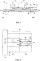
- a turbomachine component 10 is provided as, for example, a downstream section of a combustor in a gas turbine engine.
- the turbomachine component 10 includes a first vessel 20, such as a combustor liner, a second vessel 30, such as a combustor flowsleeve and one or multiple injectors 40 that are mounted to the second vessel 30 in an axially staged or late lean injection (LLI) system.
- a first vessel 20 such as a combustor liner
- a second vessel 30 such as a combustor flowsleeve
- one or multiple injectors 40 that are mounted to the second vessel 30 in an axially staged or late lean injection (LLI) system.
- LLI late lean injection
- the first vessel 20 has an upstream end 21 and a downstream end 22.
- the upstream end 21 is formed to define a first interior 210 therein in which combustion of combustible materials, such as a fuel and air, occurs.
- the downstream end 22 is formed to define a second interior 220 downstream from the first interior 210 through which products of the combustion flow as a main flow toward a transition piece and/or a turbine section.
- the second vessel 30 is configured to be disposed about at least the downstream end 220 of the first vessel 20 to define an annulus 31 between an outer surface of the first vessel 20 and an inner surface of the second vessel 30.
- the annulus 31 may be formed to define a flow path for fluid moving toward the upstream end 21 of the first vessel 20 from the transition piece 50 as impingement or cooling flow. Additional fluid/air may enter the annulus 31 in other manners as well.
- the second vessel 30 defines one or multiple micromixing injection systems 60 at one or multiple circumferential locations 61 that may be arranged with uniform or nonuniform spacing.
- Each of the one or multiple micromixing injection systems 60 at each of the one or multiple circumferential locations 61 is defined to include at least one fuel feed 70, at least one airway opening 80, at least one premixing passage 90 and a least one plenum 100.
- the at least one premixing passage 90 is fluidly coupled to the at least one fuel feed 70 and the at least one airway opening 80 and has a passage interior 91 in which fuel and air, such as compressor discharge (CDC) air, which are respectively receivable from the at least one fuel feed 70 and the at least one airway opening 80, are combinable to form a fuel and air mixture.
- the at least one plenum 100 is defined at or near a downstream end of the at least one premixing passage 90.
- the one or multiple injectors 40 are each disposed at corresponding one or multiple circumferential locations 61, respectively.
- each multiple injector 40 may be coupled to a corresponding one of the plenums 100 and may be configured to extend radially inwardly from the second vessel 30 to traverse the annulus 31 and to transport the fuel and air mixture from the second vessel 30 toward the second interior 220 of the first vessel 20 such that the fuel and air mixture may be injected to and mixed with the main flow of the products of the combustion flowing toward the transition piece and/or the turbine section.
- the second vessel 30 may include an annular body 32.
- the annular body 32 may include an upstream casing 321 and a downstream casing 322, which may be welded or otherwise fastened together.
- the upstream casing 321 is formed to define one to three or more fuel feeds 70 at each of the one or multiple circumferential locations 61.
- the downstream casing 322 is similarly formed to define at each of the multiple circumferential locations 61 a pair of airway openings 80, a pair of premixing passages 90 and a plenum 100.
- the second vessel 30 may further include a manifold 33, which is disposed about the upstream casing 321 and formed to define a fuel inlet 330 and an interior into which a fuel supply may be provided.
- the pair of premixing passages 90 may be disposed circumferentially adjacent to one another with a circumferential distance between them that is similar to a diameter of the corresponding one of the multiple injectors 40.
- Each of the pair of the premixing passages 90 extends substantially in parallel and in an axially downstream direction along a length of the downstream casing 322.
- Each of the pair of the airway openings 80 is defined at or near an upstream end of a corresponding one of the premixing passages 90 and has, for example, an elongate shape with a length that is substantially similar to a width of the associated premixing passage 90.
- a main one of the fuel feeds 70 may be disposed to extend from the manifold 33 in an axially downstream direction along a length of the upstream casing 321 at a circumferential location that is generally between the premixing passages 90.
- Fluid couplings 71 extend transversely from a downstream end of the fuel feed 70 to the premixing passages 90 downstream from the airway openings 80.
- Additional fuel feeds 70 may be disposed proximate to the main one of the fuel feeds 70 along with additional fluid couplings 71. In this way, at least one to three fuel feed(s) 70 may be provided for each one of the multiple injectors 40.
- fuel may be fed to the fuel feeds 70 by way of the fuel inlet 330 of the manifold 33.
- the fuel is then transported axially downstream by the fuel feeds 70 to the premixing passages 90.
- the fuel is mixed with CDC air entering the premixing passages 90 by way of the airway openings 80.
- the resulting fuel and air mixture is then transported axially downstream along the premixing passages 90 to the plenums 100 at which the fuel and air mixture is communicated into the multiple injectors 40.
- the multiple injectors 40 then inject the fuel and air mixture into the second interior 220 and the main flow of the products of the combustion.
Landscapes
- Engineering & Computer Science (AREA)
- Chemical & Material Sciences (AREA)
- Combustion & Propulsion (AREA)
- Mechanical Engineering (AREA)
- General Engineering & Computer Science (AREA)
- Gas Burners (AREA)
- Structures Of Non-Positive Displacement Pumps (AREA)
Applications Claiming Priority (1)
| Application Number | Priority Date | Filing Date | Title |
|---|---|---|---|
| US13/343,200 US9140455B2 (en) | 2012-01-04 | 2012-01-04 | Flowsleeve of a turbomachine component |
Publications (3)
| Publication Number | Publication Date |
|---|---|
| EP2613091A2 EP2613091A2 (en) | 2013-07-10 |
| EP2613091A3 EP2613091A3 (en) | 2013-08-28 |
| EP2613091B1 true EP2613091B1 (en) | 2017-07-26 |
Family
ID=47664069
Family Applications (1)
| Application Number | Title | Priority Date | Filing Date |
|---|---|---|---|
| EP12198319.1A Active EP2613091B1 (en) | 2012-01-04 | 2012-12-20 | Flowsleeve of a turbomachine component |
Country Status (4)
| Country | Link |
|---|---|
| US (1) | US9140455B2 (ja) |
| EP (1) | EP2613091B1 (ja) |
| JP (1) | JP5998041B2 (ja) |
| RU (1) | RU2012158344A (ja) |
Families Citing this family (5)
| Publication number | Priority date | Publication date | Assignee | Title |
|---|---|---|---|---|
| US20150159877A1 (en) * | 2013-12-06 | 2015-06-11 | General Electric Company | Late lean injection manifold mixing system |
| US10139111B2 (en) * | 2014-03-28 | 2018-11-27 | Siemens Energy, Inc. | Dual outlet nozzle for a secondary fuel stage of a combustor of a gas turbine engine |
| US9803555B2 (en) * | 2014-04-23 | 2017-10-31 | General Electric Company | Fuel delivery system with moveably attached fuel tube |
| US10578307B2 (en) | 2015-10-09 | 2020-03-03 | Dresser-Rand Company | System and method for operating a gas turbine assembly including heating a reaction/oxidation chamber |
| US10788215B2 (en) * | 2016-12-21 | 2020-09-29 | General Electric Company | Fuel nozzle assembly with flange orifice |
Family Cites Families (102)
| Publication number | Priority date | Publication date | Assignee | Title |
|---|---|---|---|---|
| GB854135A (en) | 1958-03-05 | 1960-11-16 | Rolls Royce | Improvements in or relating to combustion equipment |
| US3099134A (en) | 1959-12-24 | 1963-07-30 | Havilland Engine Co Ltd | Combustion chambers |
| US3924576A (en) | 1972-05-12 | 1975-12-09 | Gen Motors Corp | Staged combustion engines and methods of operation |
| FR2221621B1 (ja) | 1973-03-13 | 1976-09-10 | Snecma | |
| US3872664A (en) | 1973-10-15 | 1975-03-25 | United Aircraft Corp | Swirl combustor with vortex burning and mixing |
| US4028888A (en) | 1974-05-03 | 1977-06-14 | Norwalk-Turbo Inc. | Fuel distribution manifold to an annular combustion chamber |
| US4271674A (en) | 1974-10-17 | 1981-06-09 | United Technologies Corporation | Premix combustor assembly |
| DE2629761A1 (de) | 1976-07-02 | 1978-01-05 | Volkswagenwerk Ag | Brennkammer fuer gasturbinen |
| US4112676A (en) * | 1977-04-05 | 1978-09-12 | Westinghouse Electric Corp. | Hybrid combustor with staged injection of pre-mixed fuel |
| US4236378A (en) | 1978-03-01 | 1980-12-02 | General Electric Company | Sectoral combustor for burning low-BTU fuel gas |
| US4265615A (en) | 1978-12-11 | 1981-05-05 | United Technologies Corporation | Fuel injection system for low emission burners |
| US4420929A (en) | 1979-01-12 | 1983-12-20 | General Electric Company | Dual stage-dual mode low emission gas turbine combustion system |
| US4590769A (en) | 1981-01-12 | 1986-05-27 | United Technologies Corporation | High-performance burner construction |
| US4426841A (en) * | 1981-07-02 | 1984-01-24 | General Motors Corporation | Gas turbine combustor assembly |
| US4543894A (en) | 1983-05-17 | 1985-10-01 | Union Oil Company Of California | Process for staged combustion of retorted oil shale |
| JPS6057131A (ja) | 1983-09-08 | 1985-04-02 | Hitachi Ltd | ガスタ−ビン燃焼器の燃料供給方法 |
| EP0169431B1 (en) | 1984-07-10 | 1990-04-11 | Hitachi, Ltd. | Gas turbine combustor |
| JPH0752014B2 (ja) | 1986-03-20 | 1995-06-05 | 株式会社日立製作所 | ガスタ−ビン燃焼器 |
| JPH01114623A (ja) | 1987-10-27 | 1989-05-08 | Toshiba Corp | ガスタービン燃焼器 |
| US4928481A (en) | 1988-07-13 | 1990-05-29 | Prutech Ii | Staged low NOx premix gas turbine combustor |
| JPH0684817B2 (ja) | 1988-08-08 | 1994-10-26 | 株式会社日立製作所 | ガスタービン燃焼器及びその運転方法 |
| US4989549A (en) | 1988-10-11 | 1991-02-05 | Donlee Technologies, Inc. | Ultra-low NOx combustion apparatus |
| US5140808A (en) * | 1989-03-17 | 1992-08-25 | Sundstrand Corporation | Gas turbine engine with fuel mainfold system |
| US5033263A (en) * | 1989-03-17 | 1991-07-23 | Sundstrand Corporation | Compact gas turbine engine |
| US4998410A (en) | 1989-09-05 | 1991-03-12 | Rockwell International Corporation | Hybrid staged combustion-expander topping cycle engine |
| US5749219A (en) | 1989-11-30 | 1998-05-12 | United Technologies Corporation | Combustor with first and second zones |
| US5099644A (en) | 1990-04-04 | 1992-03-31 | General Electric Company | Lean staged combustion assembly |
| US5076229A (en) | 1990-10-04 | 1991-12-31 | Stanley Russel S | Internal combustion engines and method of operting an internal combustion engine using staged combustion |
| GB9023004D0 (en) * | 1990-10-23 | 1990-12-05 | Rolls Royce Plc | A gas turbine engine combustion chamber and a method of operating a gas turbine engine combustion chamber |
| US5259184A (en) | 1992-03-30 | 1993-11-09 | General Electric Company | Dry low NOx single stage dual mode combustor construction for a gas turbine |
| US5274991A (en) | 1992-03-30 | 1994-01-04 | General Electric Company | Dry low NOx multi-nozzle combustion liner cap assembly |
| US5518395A (en) | 1993-04-30 | 1996-05-21 | General Electric Company | Entrainment fuel nozzle for partial premixing of gaseous fuel and air to reduce emissions |
| GB2278431A (en) * | 1993-05-24 | 1994-11-30 | Rolls Royce Plc | A gas turbine engine combustion chamber |
| JP3335713B2 (ja) | 1993-06-28 | 2002-10-21 | 株式会社東芝 | ガスタービン燃焼器 |
| US5377483A (en) | 1993-07-07 | 1995-01-03 | Mowill; R. Jan | Process for single stage premixed constant fuel/air ratio combustion |
| US5638674A (en) | 1993-07-07 | 1997-06-17 | Mowill; R. Jan | Convectively cooled, single stage, fully premixed controllable fuel/air combustor with tangential admission |
| US5350293A (en) | 1993-07-20 | 1994-09-27 | Institute Of Gas Technology | Method for two-stage combustion utilizing forced internal recirculation |
| US5323600A (en) | 1993-08-03 | 1994-06-28 | General Electric Company | Liner stop assembly for a combustor |
| US5394688A (en) | 1993-10-27 | 1995-03-07 | Westinghouse Electric Corporation | Gas turbine combustor swirl vane arrangement |
| US5408825A (en) | 1993-12-03 | 1995-04-25 | Westinghouse Electric Corporation | Dual fuel gas turbine combustor |
| GB2284884B (en) * | 1993-12-16 | 1997-12-10 | Rolls Royce Plc | A gas turbine engine combustion chamber |
| GB9325708D0 (en) * | 1993-12-16 | 1994-02-16 | Rolls Royce Plc | A gas turbine engine combustion chamber |
| US5749218A (en) | 1993-12-17 | 1998-05-12 | General Electric Co. | Wear reduction kit for gas turbine combustors |
| JP2950720B2 (ja) | 1994-02-24 | 1999-09-20 | 株式会社東芝 | ガスタービン燃焼装置およびその燃焼制御方法 |
| AU681271B2 (en) | 1994-06-07 | 1997-08-21 | Westinghouse Electric Corporation | Method and apparatus for sequentially staged combustion using a catalyst |
| US6182451B1 (en) | 1994-09-14 | 2001-02-06 | Alliedsignal Inc. | Gas turbine combustor waving ceramic combustor cans and an annular metallic combustor |
| US5657632A (en) | 1994-11-10 | 1997-08-19 | Westinghouse Electric Corporation | Dual fuel gas turbine combustor |
| JP3502171B2 (ja) | 1994-12-05 | 2004-03-02 | 株式会社日立製作所 | ガスタービンの制御方法 |
| US5687571A (en) | 1995-02-20 | 1997-11-18 | Asea Brown Boveri Ag | Combustion chamber with two-stage combustion |
| DE19510744A1 (de) | 1995-03-24 | 1996-09-26 | Abb Management Ag | Brennkammer mit Zweistufenverbrennung |
| US5619855A (en) * | 1995-06-07 | 1997-04-15 | General Electric Company | High inlet mach combustor for gas turbine engine |
| US5647215A (en) | 1995-11-07 | 1997-07-15 | Westinghouse Electric Corporation | Gas turbine combustor with turbulence enhanced mixing fuel injectors |
| US5826429A (en) | 1995-12-22 | 1998-10-27 | General Electric Co. | Catalytic combustor with lean direct injection of gas fuel for low emissions combustion and methods of operation |
| US6201029B1 (en) | 1996-02-13 | 2001-03-13 | Marathon Oil Company | Staged combustion of a low heating value fuel gas for driving a gas turbine |
| GB2311596B (en) | 1996-03-29 | 2000-07-12 | Europ Gas Turbines Ltd | Combustor for gas - or liquid - fuelled turbine |
| US20010049932A1 (en) | 1996-05-02 | 2001-12-13 | Beebe Kenneth W. | Premixing dry low NOx emissions combustor with lean direct injection of gas fuel |
| US6047550A (en) | 1996-05-02 | 2000-04-11 | General Electric Co. | Premixing dry low NOx emissions combustor with lean direct injection of gas fuel |
| EP0911583B1 (de) * | 1997-10-27 | 2003-03-12 | ALSTOM (Switzerland) Ltd | Verfahren zum Betrieb eines Vormischbrenners |
| CA2225263A1 (en) * | 1997-12-19 | 1999-06-19 | Rolls-Royce Plc | Fluid manifold |
| US6092363A (en) | 1998-06-19 | 2000-07-25 | Siemens Westinghouse Power Corporation | Low Nox combustor having dual fuel injection system |
| JP2000008880A (ja) * | 1998-06-19 | 2000-01-11 | Toshiba Corp | ガスタービン燃焼装置 |
| US6343462B1 (en) | 1998-11-13 | 2002-02-05 | Praxair Technology, Inc. | Gas turbine power augmentation by the addition of nitrogen and moisture to the fuel gas |
| US6705117B2 (en) | 1999-08-16 | 2004-03-16 | The Boc Group, Inc. | Method of heating a glass melting furnace using a roof mounted, staged combustion oxygen-fuel burner |
| GB9929601D0 (en) * | 1999-12-16 | 2000-02-09 | Rolls Royce Plc | A combustion chamber |
| GB0019533D0 (en) * | 2000-08-10 | 2000-09-27 | Rolls Royce Plc | A combustion chamber |
| US6415608B1 (en) | 2000-09-26 | 2002-07-09 | Siemens Westinghouse Power Corporation | Piloted rich-catalytic lean-burn hybrid combustor |
| US6289851B1 (en) | 2000-10-18 | 2001-09-18 | Institute Of Gas Technology | Compact low-nox high-efficiency heating apparatus |
| JP3945152B2 (ja) | 2000-11-21 | 2007-07-18 | 日産自動車株式会社 | 内燃機関の燃焼制御装置 |
| DE10104150A1 (de) | 2001-01-30 | 2002-09-05 | Alstom Switzerland Ltd | Brenneranlage und Verfahren zu ihrem Betrieb |
| GB0111788D0 (en) * | 2001-05-15 | 2001-07-04 | Rolls Royce Plc | A combustion chamber |
| US6620457B2 (en) | 2001-07-13 | 2003-09-16 | General Electric Company | Method for thermal barrier coating and a liner made using said method |
| US20030024234A1 (en) | 2001-08-02 | 2003-02-06 | Siemens Westinghouse Power Corporation | Secondary combustor for low NOx gas combustion turbine |
| US6663380B2 (en) | 2001-09-05 | 2003-12-16 | Gas Technology Institute | Method and apparatus for advanced staged combustion utilizing forced internal recirculation |
| US6775987B2 (en) | 2002-09-12 | 2004-08-17 | The Boeing Company | Low-emission, staged-combustion power generation |
| US7040094B2 (en) | 2002-09-20 | 2006-05-09 | The Regents Of The University Of California | Staged combustion with piston engine and turbine engine supercharger |
| US6868676B1 (en) | 2002-12-20 | 2005-03-22 | General Electric Company | Turbine containing system and an injector therefor |
| US7149632B1 (en) | 2003-03-10 | 2006-12-12 | General Electric Company | On-line system and method for processing information relating to the wear of turbine components |
| GB0323255D0 (en) * | 2003-10-04 | 2003-11-05 | Rolls Royce Plc | Method and system for controlling fuel supply in a combustion turbine engine |
| US7082770B2 (en) | 2003-12-24 | 2006-08-01 | Martling Vincent C | Flow sleeve for a low NOx combustor |
| US7302801B2 (en) | 2004-04-19 | 2007-12-04 | Hamilton Sundstrand Corporation | Lean-staged pyrospin combustor |
| US7185497B2 (en) | 2004-05-04 | 2007-03-06 | Honeywell International, Inc. | Rich quick mix combustion system |
| US7303388B2 (en) | 2004-07-01 | 2007-12-04 | Air Products And Chemicals, Inc. | Staged combustion system with ignition-assisted fuel lances |
| US20060107667A1 (en) * | 2004-11-22 | 2006-05-25 | Haynes Joel M | Trapped vortex combustor cavity manifold for gas turbine engine |
| US7707835B2 (en) | 2005-06-15 | 2010-05-04 | General Electric Company | Axial flow sleeve for a turbine combustor and methods of introducing flow sleeve air |
| US7568343B2 (en) | 2005-09-12 | 2009-08-04 | Florida Turbine Technologies, Inc. | Small gas turbine engine with multiple burn zones |
| US7685823B2 (en) | 2005-10-28 | 2010-03-30 | Power Systems Mfg., Llc | Airflow distribution to a low emissions combustor |
| US7926286B2 (en) | 2006-09-26 | 2011-04-19 | Pratt & Whitney Canada Corp. | Heat shield for a fuel manifold |
| US7886545B2 (en) | 2007-04-27 | 2011-02-15 | General Electric Company | Methods and systems to facilitate reducing NOx emissions in combustion systems |
| US8387398B2 (en) | 2007-09-14 | 2013-03-05 | Siemens Energy, Inc. | Apparatus and method for controlling the secondary injection of fuel |
| US7757491B2 (en) | 2008-05-09 | 2010-07-20 | General Electric Company | Fuel nozzle for a gas turbine engine and method for fabricating the same |
| US8528340B2 (en) | 2008-07-28 | 2013-09-10 | Siemens Energy, Inc. | Turbine engine flow sleeve |
| EP2161500A1 (en) | 2008-09-04 | 2010-03-10 | Siemens Aktiengesellschaft | Combustor system and method of reducing combustion instability and/or emissions of a combustor system |
| US8683808B2 (en) | 2009-01-07 | 2014-04-01 | General Electric Company | Late lean injection control strategy |
| US8112216B2 (en) | 2009-01-07 | 2012-02-07 | General Electric Company | Late lean injection with adjustable air splits |
| US8701383B2 (en) | 2009-01-07 | 2014-04-22 | General Electric Company | Late lean injection system configuration |
| US8701382B2 (en) | 2009-01-07 | 2014-04-22 | General Electric Company | Late lean injection with expanded fuel flexibility |
| US8701418B2 (en) | 2009-01-07 | 2014-04-22 | General Electric Company | Late lean injection for fuel flexibility |
| US8707707B2 (en) | 2009-01-07 | 2014-04-29 | General Electric Company | Late lean injection fuel staging configurations |
| US8539773B2 (en) * | 2009-02-04 | 2013-09-24 | General Electric Company | Premixed direct injection nozzle for highly reactive fuels |
| EP2475934A4 (en) * | 2009-09-13 | 2015-02-11 | Lean Flame Inc | FORWARD PRE-MIXING APPARATUS FOR COMBUSTION APPARATUS |
| US8769955B2 (en) * | 2010-06-02 | 2014-07-08 | Siemens Energy, Inc. | Self-regulating fuel staging port for turbine combustor |
| US9404659B2 (en) * | 2012-12-17 | 2016-08-02 | General Electric Company | Systems and methods for late lean injection premixing |
-
2012
- 2012-01-04 US US13/343,200 patent/US9140455B2/en active Active
- 2012-12-20 EP EP12198319.1A patent/EP2613091B1/en active Active
- 2012-12-21 JP JP2012278795A patent/JP5998041B2/ja active Active
- 2012-12-27 RU RU2012158344/06A patent/RU2012158344A/ru not_active Application Discontinuation
Non-Patent Citations (1)
| Title |
|---|
| None * |
Also Published As
| Publication number | Publication date |
|---|---|
| US9140455B2 (en) | 2015-09-22 |
| JP5998041B2 (ja) | 2016-09-28 |
| RU2012158344A (ru) | 2014-07-10 |
| JP2013140007A (ja) | 2013-07-18 |
| EP2613091A3 (en) | 2013-08-28 |
| US20130167542A1 (en) | 2013-07-04 |
| EP2613091A2 (en) | 2013-07-10 |
Similar Documents
| Publication | Publication Date | Title |
|---|---|---|
| US8904798B2 (en) | Combustor | |
| US10502426B2 (en) | Dual fuel injectors and methods of use in gas turbine combustor | |
| EP2639508B1 (en) | System for supplying a working fluid to a combustor | |
| EP2613082B1 (en) | System and method for supplying a working fluid to a combustor | |
| US9534790B2 (en) | Fuel injector for supplying fuel to a combustor | |
| US9212822B2 (en) | Fuel injection assembly for use in turbine engines and method of assembling same | |
| EP3220047B1 (en) | Gas turbine flow sleeve mounting | |
| EP3450849B1 (en) | Fuel injector for a combustor of a gas turbine | |
| US10690350B2 (en) | Combustor with axially staged fuel injection | |
| US9404659B2 (en) | Systems and methods for late lean injection premixing | |
| EP3341656B1 (en) | Fuel nozzle assembly for a gas turbine | |
| EP2788685B1 (en) | Multi-zone combustor | |
| EP2613091B1 (en) | Flowsleeve of a turbomachine component | |
| US11156362B2 (en) | Combustor with axially staged fuel injection | |
| US9127844B2 (en) | Fuel nozzle | |
| US20180340689A1 (en) | Low Profile Axially Staged Fuel Injector | |
| EP3586062B1 (en) | Combustion system with axially staged fuel injection | |
| US20140137560A1 (en) | Turbomachine with trapped vortex feature | |
| US11255545B1 (en) | Integrated combustion nozzle having a unified head end | |
| US20130227928A1 (en) | Fuel nozzle assembly for use in turbine engines and method of assembling same | |
| CN103925617B (zh) | 涡轮机械构件的流套 | |
| US10228135B2 (en) | Combustion liner cooling |
Legal Events
| Date | Code | Title | Description |
|---|---|---|---|
| PUAI | Public reference made under article 153(3) epc to a published international application that has entered the european phase |
Free format text: ORIGINAL CODE: 0009012 |
|
| AK | Designated contracting states |
Kind code of ref document: A2 Designated state(s): AL AT BE BG CH CY CZ DE DK EE ES FI FR GB GR HR HU IE IS IT LI LT LU LV MC MK MT NL NO PL PT RO RS SE SI SK SM TR |
|
| AX | Request for extension of the european patent |
Extension state: BA ME |
|
| PUAL | Search report despatched |
Free format text: ORIGINAL CODE: 0009013 |
|
| AK | Designated contracting states |
Kind code of ref document: A3 Designated state(s): AL AT BE BG CH CY CZ DE DK EE ES FI FR GB GR HR HU IE IS IT LI LT LU LV MC MK MT NL NO PL PT RO RS SE SI SK SM TR |
|
| AX | Request for extension of the european patent |
Extension state: BA ME |
|
| RIC1 | Information provided on ipc code assigned before grant |
Ipc: F23R 3/54 20060101ALI20130724BHEP Ipc: F23R 3/28 20060101AFI20130724BHEP Ipc: F23R 3/34 20060101ALI20130724BHEP |
|
| 17P | Request for examination filed |
Effective date: 20140228 |
|
| RBV | Designated contracting states (corrected) |
Designated state(s): AL AT BE BG CH CY CZ DE DK EE ES FI FR GB GR HR HU IE IS IT LI LT LU LV MC MK MT NL NO PL PT RO RS SE SI SK SM TR |
|
| GRAP | Despatch of communication of intention to grant a patent |
Free format text: ORIGINAL CODE: EPIDOSNIGR1 |
|
| INTG | Intention to grant announced |
Effective date: 20170328 |
|
| GRAS | Grant fee paid |
Free format text: ORIGINAL CODE: EPIDOSNIGR3 |
|
| GRAA | (expected) grant |
Free format text: ORIGINAL CODE: 0009210 |
|
| AK | Designated contracting states |
Kind code of ref document: B1 Designated state(s): AL AT BE BG CH CY CZ DE DK EE ES FI FR GB GR HR HU IE IS IT LI LT LU LV MC MK MT NL NO PL PT RO RS SE SI SK SM TR |
|
| REG | Reference to a national code |
Ref country code: GB Ref legal event code: FG4D |
|
| REG | Reference to a national code |
Ref country code: CH Ref legal event code: EP |
|
| REG | Reference to a national code |
Ref country code: AT Ref legal event code: REF Ref document number: 912693 Country of ref document: AT Kind code of ref document: T Effective date: 20170815 |
|
| REG | Reference to a national code |
Ref country code: IE Ref legal event code: FG4D |
|
| REG | Reference to a national code |
Ref country code: DE Ref legal event code: R096 Ref document number: 602012034966 Country of ref document: DE |
|
| REG | Reference to a national code |
Ref country code: NL Ref legal event code: MP Effective date: 20170726 |
|
| REG | Reference to a national code |
Ref country code: LT Ref legal event code: MG4D |
|
| REG | Reference to a national code |
Ref country code: AT Ref legal event code: MK05 Ref document number: 912693 Country of ref document: AT Kind code of ref document: T Effective date: 20170726 |
|
| PG25 | Lapsed in a contracting state [announced via postgrant information from national office to epo] |
Ref country code: SE Free format text: LAPSE BECAUSE OF FAILURE TO SUBMIT A TRANSLATION OF THE DESCRIPTION OR TO PAY THE FEE WITHIN THE PRESCRIBED TIME-LIMIT Effective date: 20170726 Ref country code: AT Free format text: LAPSE BECAUSE OF FAILURE TO SUBMIT A TRANSLATION OF THE DESCRIPTION OR TO PAY THE FEE WITHIN THE PRESCRIBED TIME-LIMIT Effective date: 20170726 Ref country code: FI Free format text: LAPSE BECAUSE OF FAILURE TO SUBMIT A TRANSLATION OF THE DESCRIPTION OR TO PAY THE FEE WITHIN THE PRESCRIBED TIME-LIMIT Effective date: 20170726 Ref country code: NO Free format text: LAPSE BECAUSE OF FAILURE TO SUBMIT A TRANSLATION OF THE DESCRIPTION OR TO PAY THE FEE WITHIN THE PRESCRIBED TIME-LIMIT Effective date: 20171026 Ref country code: NL Free format text: LAPSE BECAUSE OF FAILURE TO SUBMIT A TRANSLATION OF THE DESCRIPTION OR TO PAY THE FEE WITHIN THE PRESCRIBED TIME-LIMIT Effective date: 20170726 Ref country code: HR Free format text: LAPSE BECAUSE OF FAILURE TO SUBMIT A TRANSLATION OF THE DESCRIPTION OR TO PAY THE FEE WITHIN THE PRESCRIBED TIME-LIMIT Effective date: 20170726 Ref country code: LT Free format text: LAPSE BECAUSE OF FAILURE TO SUBMIT A TRANSLATION OF THE DESCRIPTION OR TO PAY THE FEE WITHIN THE PRESCRIBED TIME-LIMIT Effective date: 20170726 |
|
| PG25 | Lapsed in a contracting state [announced via postgrant information from national office to epo] |
Ref country code: LV Free format text: LAPSE BECAUSE OF FAILURE TO SUBMIT A TRANSLATION OF THE DESCRIPTION OR TO PAY THE FEE WITHIN THE PRESCRIBED TIME-LIMIT Effective date: 20170726 Ref country code: IS Free format text: LAPSE BECAUSE OF FAILURE TO SUBMIT A TRANSLATION OF THE DESCRIPTION OR TO PAY THE FEE WITHIN THE PRESCRIBED TIME-LIMIT Effective date: 20171126 Ref country code: PL Free format text: LAPSE BECAUSE OF FAILURE TO SUBMIT A TRANSLATION OF THE DESCRIPTION OR TO PAY THE FEE WITHIN THE PRESCRIBED TIME-LIMIT Effective date: 20170726 Ref country code: BG Free format text: LAPSE BECAUSE OF FAILURE TO SUBMIT A TRANSLATION OF THE DESCRIPTION OR TO PAY THE FEE WITHIN THE PRESCRIBED TIME-LIMIT Effective date: 20171026 Ref country code: ES Free format text: LAPSE BECAUSE OF FAILURE TO SUBMIT A TRANSLATION OF THE DESCRIPTION OR TO PAY THE FEE WITHIN THE PRESCRIBED TIME-LIMIT Effective date: 20170726 Ref country code: GR Free format text: LAPSE BECAUSE OF FAILURE TO SUBMIT A TRANSLATION OF THE DESCRIPTION OR TO PAY THE FEE WITHIN THE PRESCRIBED TIME-LIMIT Effective date: 20171027 Ref country code: RS Free format text: LAPSE BECAUSE OF FAILURE TO SUBMIT A TRANSLATION OF THE DESCRIPTION OR TO PAY THE FEE WITHIN THE PRESCRIBED TIME-LIMIT Effective date: 20170726 |
|
| PG25 | Lapsed in a contracting state [announced via postgrant information from national office to epo] |
Ref country code: DK Free format text: LAPSE BECAUSE OF FAILURE TO SUBMIT A TRANSLATION OF THE DESCRIPTION OR TO PAY THE FEE WITHIN THE PRESCRIBED TIME-LIMIT Effective date: 20170726 Ref country code: CZ Free format text: LAPSE BECAUSE OF FAILURE TO SUBMIT A TRANSLATION OF THE DESCRIPTION OR TO PAY THE FEE WITHIN THE PRESCRIBED TIME-LIMIT Effective date: 20170726 Ref country code: RO Free format text: LAPSE BECAUSE OF FAILURE TO SUBMIT A TRANSLATION OF THE DESCRIPTION OR TO PAY THE FEE WITHIN THE PRESCRIBED TIME-LIMIT Effective date: 20170726 |
|
| REG | Reference to a national code |
Ref country code: DE Ref legal event code: R097 Ref document number: 602012034966 Country of ref document: DE |
|
| PG25 | Lapsed in a contracting state [announced via postgrant information from national office to epo] |
Ref country code: SM Free format text: LAPSE BECAUSE OF FAILURE TO SUBMIT A TRANSLATION OF THE DESCRIPTION OR TO PAY THE FEE WITHIN THE PRESCRIBED TIME-LIMIT Effective date: 20170726 Ref country code: EE Free format text: LAPSE BECAUSE OF FAILURE TO SUBMIT A TRANSLATION OF THE DESCRIPTION OR TO PAY THE FEE WITHIN THE PRESCRIBED TIME-LIMIT Effective date: 20170726 Ref country code: SK Free format text: LAPSE BECAUSE OF FAILURE TO SUBMIT A TRANSLATION OF THE DESCRIPTION OR TO PAY THE FEE WITHIN THE PRESCRIBED TIME-LIMIT Effective date: 20170726 |
|
| PLBE | No opposition filed within time limit |
Free format text: ORIGINAL CODE: 0009261 |
|
| STAA | Information on the status of an ep patent application or granted ep patent |
Free format text: STATUS: NO OPPOSITION FILED WITHIN TIME LIMIT |
|
| 26N | No opposition filed |
Effective date: 20180430 |
|
| REG | Reference to a national code |
Ref country code: CH Ref legal event code: PL |
|
| GBPC | Gb: european patent ceased through non-payment of renewal fee |
Effective date: 20171220 |
|
| PG25 | Lapsed in a contracting state [announced via postgrant information from national office to epo] |
Ref country code: SI Free format text: LAPSE BECAUSE OF FAILURE TO SUBMIT A TRANSLATION OF THE DESCRIPTION OR TO PAY THE FEE WITHIN THE PRESCRIBED TIME-LIMIT Effective date: 20170726 |
|
| REG | Reference to a national code |
Ref country code: IE Ref legal event code: MM4A |
|
| PG25 | Lapsed in a contracting state [announced via postgrant information from national office to epo] |
Ref country code: MT Free format text: LAPSE BECAUSE OF NON-PAYMENT OF DUE FEES Effective date: 20171220 Ref country code: LU Free format text: LAPSE BECAUSE OF NON-PAYMENT OF DUE FEES Effective date: 20171220 |
|
| REG | Reference to a national code |
Ref country code: FR Ref legal event code: ST Effective date: 20180831 |
|
| REG | Reference to a national code |
Ref country code: BE Ref legal event code: MM Effective date: 20171231 |
|
| PG25 | Lapsed in a contracting state [announced via postgrant information from national office to epo] |
Ref country code: IE Free format text: LAPSE BECAUSE OF NON-PAYMENT OF DUE FEES Effective date: 20171220 Ref country code: FR Free format text: LAPSE BECAUSE OF NON-PAYMENT OF DUE FEES Effective date: 20180102 |
|
| PG25 | Lapsed in a contracting state [announced via postgrant information from national office to epo] |
Ref country code: BE Free format text: LAPSE BECAUSE OF NON-PAYMENT OF DUE FEES Effective date: 20171231 Ref country code: GB Free format text: LAPSE BECAUSE OF NON-PAYMENT OF DUE FEES Effective date: 20171220 Ref country code: CH Free format text: LAPSE BECAUSE OF NON-PAYMENT OF DUE FEES Effective date: 20171231 Ref country code: LI Free format text: LAPSE BECAUSE OF NON-PAYMENT OF DUE FEES Effective date: 20171231 |
|
| PG25 | Lapsed in a contracting state [announced via postgrant information from national office to epo] |
Ref country code: HU Free format text: LAPSE BECAUSE OF FAILURE TO SUBMIT A TRANSLATION OF THE DESCRIPTION OR TO PAY THE FEE WITHIN THE PRESCRIBED TIME-LIMIT; INVALID AB INITIO Effective date: 20121220 Ref country code: MC Free format text: LAPSE BECAUSE OF FAILURE TO SUBMIT A TRANSLATION OF THE DESCRIPTION OR TO PAY THE FEE WITHIN THE PRESCRIBED TIME-LIMIT Effective date: 20170726 |
|
| PG25 | Lapsed in a contracting state [announced via postgrant information from national office to epo] |
Ref country code: CY Free format text: LAPSE BECAUSE OF NON-PAYMENT OF DUE FEES Effective date: 20170726 |
|
| PG25 | Lapsed in a contracting state [announced via postgrant information from national office to epo] |
Ref country code: MK Free format text: LAPSE BECAUSE OF FAILURE TO SUBMIT A TRANSLATION OF THE DESCRIPTION OR TO PAY THE FEE WITHIN THE PRESCRIBED TIME-LIMIT Effective date: 20170726 |
|
| PGFP | Annual fee paid to national office [announced via postgrant information from national office to epo] |
Ref country code: IT Payment date: 20191121 Year of fee payment: 8 |
|
| PG25 | Lapsed in a contracting state [announced via postgrant information from national office to epo] |
Ref country code: TR Free format text: LAPSE BECAUSE OF FAILURE TO SUBMIT A TRANSLATION OF THE DESCRIPTION OR TO PAY THE FEE WITHIN THE PRESCRIBED TIME-LIMIT Effective date: 20170726 |
|
| PG25 | Lapsed in a contracting state [announced via postgrant information from national office to epo] |
Ref country code: PT Free format text: LAPSE BECAUSE OF FAILURE TO SUBMIT A TRANSLATION OF THE DESCRIPTION OR TO PAY THE FEE WITHIN THE PRESCRIBED TIME-LIMIT Effective date: 20170726 |
|
| PG25 | Lapsed in a contracting state [announced via postgrant information from national office to epo] |
Ref country code: AL Free format text: LAPSE BECAUSE OF FAILURE TO SUBMIT A TRANSLATION OF THE DESCRIPTION OR TO PAY THE FEE WITHIN THE PRESCRIBED TIME-LIMIT Effective date: 20170726 |
|
| PG25 | Lapsed in a contracting state [announced via postgrant information from national office to epo] |
Ref country code: IT Free format text: LAPSE BECAUSE OF NON-PAYMENT OF DUE FEES Effective date: 20201220 |
|
| REG | Reference to a national code |
Ref country code: DE Ref legal event code: R081 Ref document number: 602012034966 Country of ref document: DE Owner name: GENERAL ELECTRIC TECHNOLOGY GMBH, CH Free format text: FORMER OWNER: GENERAL ELECTRIC COMPANY, SCHENECTADY, NY, US |
|
| PGFP | Annual fee paid to national office [announced via postgrant information from national office to epo] |
Ref country code: DE Payment date: 20231121 Year of fee payment: 12 |