EP2613036A2 - Gas turbine inlet system - Google Patents
Gas turbine inlet system Download PDFInfo
- Publication number
- EP2613036A2 EP2613036A2 EP12198340.7A EP12198340A EP2613036A2 EP 2613036 A2 EP2613036 A2 EP 2613036A2 EP 12198340 A EP12198340 A EP 12198340A EP 2613036 A2 EP2613036 A2 EP 2613036A2
- Authority
- EP
- European Patent Office
- Prior art keywords
- silencing
- gas turbine
- airflow
- turbine inlet
- inlet system
- Prior art date
- Legal status (The legal status is an assumption and is not a legal conclusion. Google has not performed a legal analysis and makes no representation as to the accuracy of the status listed.)
- Withdrawn
Links
- 230000003584 silencer Effects 0.000 claims abstract description 50
- 230000030279 gene silencing Effects 0.000 claims abstract description 44
- 230000007704 transition Effects 0.000 claims description 20
- 239000000463 material Substances 0.000 claims description 4
- 230000007423 decrease Effects 0.000 claims 2
- 239000011358 absorbing material Substances 0.000 claims 1
- 238000011144 upstream manufacturing Methods 0.000 description 7
- 230000000694 effects Effects 0.000 description 3
- 230000009467 reduction Effects 0.000 description 3
- 229910003460 diamond Inorganic materials 0.000 description 2
- 239000010432 diamond Substances 0.000 description 2
- 230000004075 alteration Effects 0.000 description 1
- 238000000034 method Methods 0.000 description 1
- 239000011490 mineral wool Substances 0.000 description 1
- 230000008569 process Effects 0.000 description 1
- 238000004080 punching Methods 0.000 description 1
- 229910001220 stainless steel Inorganic materials 0.000 description 1
- 239000010935 stainless steel Substances 0.000 description 1
- 238000006467 substitution reaction Methods 0.000 description 1
Images


Classifications
-
- F—MECHANICAL ENGINEERING; LIGHTING; HEATING; WEAPONS; BLASTING
- F02—COMBUSTION ENGINES; HOT-GAS OR COMBUSTION-PRODUCT ENGINE PLANTS
- F02C—GAS-TURBINE PLANTS; AIR INTAKES FOR JET-PROPULSION PLANTS; CONTROLLING FUEL SUPPLY IN AIR-BREATHING JET-PROPULSION PLANTS
- F02C7/00—Features, components parts, details or accessories, not provided for in, or of interest apart form groups F02C1/00 - F02C6/00; Air intakes for jet-propulsion plants
- F02C7/04—Air intakes for gas-turbine plants or jet-propulsion plants
- F02C7/045—Air intakes for gas-turbine plants or jet-propulsion plants having provisions for noise suppression
-
- F—MECHANICAL ENGINEERING; LIGHTING; HEATING; WEAPONS; BLASTING
- F05—INDEXING SCHEMES RELATING TO ENGINES OR PUMPS IN VARIOUS SUBCLASSES OF CLASSES F01-F04
- F05D—INDEXING SCHEME FOR ASPECTS RELATING TO NON-POSITIVE-DISPLACEMENT MACHINES OR ENGINES, GAS-TURBINES OR JET-PROPULSION PLANTS
- F05D2260/00—Function
- F05D2260/96—Preventing, counteracting or reducing vibration or noise
Definitions
- the subject matter disclosed herein relates to gas turbine systems, and more particularly to inlet silencers of such systems.
- a gas turbine inlet system includes a distinct duct to house 8-12 foot long baffles that function as silencers.
- the baffles are aligned longitudinally and in parallel with inlet airflow direction.
- the inlet airflow passes through gaps defined by the baffles and provide a direct line of sight for reverberating sound waves passing upstream through the gaps of the baffles. Therefore, the sound waves are permitted to travel in an uninterrupted manner toward a main inlet of the gas turbine inlet system. Furthermore, such an uninterrupted path within the gap allows for enhanced airflow velocity to result in an undesirably high pressure drop throughout the gas turbine inlet system.
- a gas turbine inlet system includes a main inlet portion, wherein an airflow is introduced to the gas turbine inlet system. Also included is a silencer assembly.
- the silencer assembly includes a first silencing panel, wherein the first silencing panel is oriented substantially perpendicularly to the airflow, and wherein the first silencing panel includes a first plurality of airflow apertures.
- the silencer assembly also includes a second silencing panel, wherein the second silencing panel is oriented substantially perpendicularly to the airflow, and wherein the second silencing panel includes a second plurality of airflow apertures.
- a gas turbine inlet system includes a main inlet portion, wherein an airflow is introduced to the gas turbine inlet system. Also included is a first group of parallel silencing panels that are oriented substantially perpendicularly to the airflow, wherein the first group of parallel silencing panels include a first plurality of gaps therebetween. Further included is a second group of parallel silencing panels that are oriented substantially perpendicularly to the airflow, wherein the second group of parallel silencing panels includes a second plurality of gaps therebetween, wherein the first plurality of gaps is aligned in a first series of airflow planes and the second plurality of gaps is aligned in a distinct second series of airflow planes.
- a gas turbine inlet system includes a main inlet portion, wherein an airflow is introduced to the gas turbine inlet system.
- the gas turbine inlet system also includes a silencer assembly including a first plurality of silencing panels having a first alignment and a second plurality of silencing panels having a second alignment.
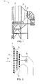
- a gas turbine inlet system 10 includes a main inlet portion 12 configured to receive an airflow 14 traveling predominantly in a first direction.
- the airflow 14 travels from the main inlet portion 12 through a transition duct 16 that narrows in a downstream direction and into various other portions of the gas turbine inlet system 10.
- a silencer assembly 18 is disposed, at least in part, within the transition duct 16 and functions to dampen the sound associated with reverberating sound waves 20 that are generated by the gas turbine inlet system 10 and gas turbine itself as the airflow 14 passes through them.
- the sound waves 20 travel substantially opposite in direction to the airflow 14 and thereby interact with the silencer assembly 18 disposed within the transition duct 16.
- the presence of the silencer assembly 18 results in a flow rate of the airflow 14 that is higher than that of a flow rate produced in an inlet system that has silencers located in a smaller duct downstream of the transition duct 16.
- the silencer assembly 18 includes at least one, and typically a plurality of, silencer panels 22 that are arranged relatively parallel to each other.
- the illustrated silencer panels 22 have a relatively rectangular or square geometry that corresponds to an interior surface 23 of the transition duct 16. It is also conceivable that various other geometries may be employed to suit the configuration of the transition duct 16.
- the silencer panels 22 are disposed in series and each have an outer perimeter 24. When disposed within the transition duct 16, the outer perimeter 24 of the silencer panels 22 located downstream is smaller than that of the outer perimeter 24 of respective upstream silencer panels 22. This is due to the narrowing of the transition duct 16 in the downstream direction.
- the silencer panels 22 are described as having smaller successive outer perimeters 24, it should be appreciated that silencer panels 22 having relatively similar outer perimeters 24 may be employed in a housing conducive to such similar outer perimeters 24.
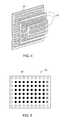
- the silencer panel 22 is typically a planar sheet and may be formed of a durable material, such as stainless steel or any other stiff material, for example, and may include a plurality of perforations 26 therein. The perforations are lined with a sound dampening material, such as mineral wool.
- a plurality of airflow apertures 28 are imposed on the silencer panel 22 and may be formed by a punching process.
- the airflow apertures 28 may take on various geometric configurations including, but not limited to, circular, rectangular, squared, diamond-shaped, or oval. These are merely illustrative examples of numerous configurations that the airflow apertures 28 may take on.
- the plurality of airflow apertures 28 allow the airflow 14 to pass through the transition duct 16, yet as a result of the staggered orientation of the silencer panels 22, and therefore their respective airflow apertures 28, fewer, if any, direct "sightlines" are present throughout the transition duct 16.
- the term "sightlines” refers to an alignment of the airflow apertures 28 in a direction of airflow 14.
- the silencer assembly 18 also functions to reduce the pressure drop seen throughout the gas turbine inlet system 10. This is a function of the reduction in flow velocity of the airflow 14, as compared to a system having the silencers located in a smaller duct downstream of the transition duct 16.
- the silencer assembly includes a plurality of panel groups 102 that each comprise a plurality of panels 104.
- the plurality of panel groups 102 are disposed, at least in part, within the transition duct 16 and the plurality of panels 104 are disposed relatively horizontally or vertically (horizontal with respect to illustration) and relatively perpendicular to the airflow 14.
- the panels 104 of each panel group 102 are oriented relatively parallel to one another and are aligned in a relatively vertical or horizontal arrangement (vertical with respect to illustration).
- a plurality of gaps 106 are present within each panel group 102 and are defined by respective pairs of panels 104.
- the plurality of panel groups 102 are disposed in series and are each defined by an outer perimeter 124.
- the outer perimeter 124 of the plurality of panel groups 102 located downstream is smaller than that of the outer perimeter 124 of respective upstream plurality of panel groups 102.
- the panel groups 102 having relatively similar outer perimeters 124 may be employed in a housing conducive to such similar outer perimeters 124.
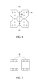
- the orientation of the plurality of panel groups 102 is more closely illustrated.
- the plurality of panel groups 102 are arranged to reduce the number of "sightlines," thereby reducing the ability of a sound wave 20 to propagate in an unimpeded manner through the silencer assembly 100.
- the plurality of panels 104 are configured, such that downstream panels 104 substantially align with the upstream gaps 106.
- a panel group disposed immediately downstream of another panel group is aligned such that the downstream panels effectively close out the upstream gaps, and may include a slight overlap with the upstream panels. Therefore, the silencer assembly 100 achieves a similar function as that of the first embodiment.
- the silencer assembly 100 dampens sound by imposing impediments to reverberating sound waves 20 within the gas turbine inlet system 10.
- numerous geometric configurations may be employed to form the panels 104. Illustrative examples include oval and diamond shaped, however it is contemplated that any number of shapes may suit the application for its intended purpose.
- the silencer assembly 100 includes the plurality of panel groups 102 that each comprise the plurality of panels 104 oriented at a desired angle to the airflow 14. As with the second embodiment of the silencer assembly 100, the downstream panels are positioned in line with the gaps 106 of the adjacent upstream panels at any desired angle to the airflow 14. In addition to the plurality of panels 104, the silencer assembly 100 may optionally include flow straighteners 108 that function to reduce swirling vortices that may be generated in the airflow 14 as a result of the passage through the plurality of panel groups 102.
- the flow straighteners 108 impart a straightening effect on the airflow 14, as swirling airflow may be undesirable. As previously described, such an alignment provides the aforementioned advantages, such as sound dampening and pressure drop reduction.
- the plurality of panels 104 may be formed in any number of shapes or geometries. Examples of such geometries include relatively diamond panels and teardrop panels. These are merely illustrative and should not be considered limiting, as numerous other geometries may be suitable.
- the silencer assembly 200 includes a plurality of panels 204 that extend longitudinally in the direction of the airflow 14, with gaps 206 disposed between the plurality of panels 204.
- the various embodiments illustrated each provide gaps 206 that do not consist of a path for the airflow that is parallel to the direction of incoming airflow 14 throughout the entire gap 206.
- the airflow 14 direction of travel must be altered in some manner as it passes through the silencer assembly 200. Again, as with previously described embodiments, this reduces the presence of direct sightlines for sound waves 20 to reverberate back through.
- the plurality of gaps 206 may be angled, with respect to each other, or relatively parallel to one another, but formed in jagged or curved paths.
- the illustrated paths formed by the gaps 206 are merely exemplary and it is contemplated that numerous other gap paths may be employed. Irrespective of the path formed by the gaps 206, the sound waves 20 are impeded from a direct line of reverberation back through the silencer assembly 200 and the velocity of the airflow 14 is reduced, resulting in an advantageous pressure drop reduction.
Landscapes
- Engineering & Computer Science (AREA)
- Chemical & Material Sciences (AREA)
- Combustion & Propulsion (AREA)
- Mechanical Engineering (AREA)
- General Engineering & Computer Science (AREA)
- Soundproofing, Sound Blocking, And Sound Damping (AREA)
- Exhaust Silencers (AREA)
- Supercharger (AREA)
- Structures Of Non-Positive Displacement Pumps (AREA)
Abstract
Description
- The subject matter disclosed herein relates to gas turbine systems, and more particularly to inlet silencers of such systems.
- Often, a gas turbine inlet system includes a distinct duct to house 8-12 foot long baffles that function as silencers. The baffles are aligned longitudinally and in parallel with inlet airflow direction. The inlet airflow passes through gaps defined by the baffles and provide a direct line of sight for reverberating sound waves passing upstream through the gaps of the baffles. Therefore, the sound waves are permitted to travel in an uninterrupted manner toward a main inlet of the gas turbine inlet system. Furthermore, such an uninterrupted path within the gap allows for enhanced airflow velocity to result in an undesirably high pressure drop throughout the gas turbine inlet system.
- According to another aspect of the invention, a gas turbine inlet system includes a main inlet portion, wherein an airflow is introduced to the gas turbine inlet system. Also included is a silencer assembly. The silencer assembly includes a first silencing panel, wherein the first silencing panel is oriented substantially perpendicularly to the airflow, and wherein the first silencing panel includes a first plurality of airflow apertures. The silencer assembly also includes a second silencing panel, wherein the second silencing panel is oriented substantially perpendicularly to the airflow, and wherein the second silencing panel includes a second plurality of airflow apertures.
- According to yet another aspect of the invention, a gas turbine inlet system includes a main inlet portion, wherein an airflow is introduced to the gas turbine inlet system. Also included is a first group of parallel silencing panels that are oriented substantially perpendicularly to the airflow, wherein the first group of parallel silencing panels include a first plurality of gaps therebetween. Further included is a second group of parallel silencing panels that are oriented substantially perpendicularly to the airflow, wherein the second group of parallel silencing panels includes a second plurality of gaps therebetween, wherein the first plurality of gaps is aligned in a first series of airflow planes and the second plurality of gaps is aligned in a distinct second series of airflow planes.
- According to one aspect of the invention, a gas turbine inlet system includes a main inlet portion, wherein an airflow is introduced to the gas turbine inlet system. The gas turbine inlet system also includes a silencer assembly including a first plurality of silencing panels having a first alignment and a second plurality of silencing panels having a second alignment.
- These and other advantages and features will become more apparent from the following description taken in conjunction with the drawings.
- The subject matter, which is regarded as the invention, is particularly pointed out and distinctly claimed in the claims at the conclusion of the specification. The foregoing and other features and advantages of the invention are apparent from the following detailed description taken in conjunction with the accompanying drawings in which:
-
FIG. 1 is a side elevational view of a gas turbine inlet system; -
FIG. 2 is a side elevational view of a transition duct of the gas turbine inlet system; -
FIG. 3 is a side perspective view of first embodiment of a silencer panel system within the transition duct; -
FIG. 4 is a rear perspective view of the first embodiment of the silencer panel system; -
FIG. 5 is a front elevational view of the first embodiment of the silencer panel; -
FIG. 6 is an enlarged front elevational view of a portion of the first embodiment of the silencer panel ofFIG. 5 ; -
FIG. 7 is a cross-sectional view of the portion of the first embodiment of the silencer panel taken along line VII-VII ofFIG. 6 ; -
FIG. 8 is a side perspective view of a second embodiment of a silencer panel system within the transition duct; -
FIG. 9 is a side perspective view of the second embodiment of the silencer panel system; -
FIG. 10 is a side elevational schematic view of the second embodiment of the silencer panel system; -
FIG. 11 is a side elevational view of the second embodiment of the silencer panel system; and -
FIG. 12 is a side elevational view of a third embodiment of the silencer panel system. - The detailed description explains embodiments of the invention, together with advantages and features, by way of example with reference to the drawings.
- Referring to
FIGS. 1 and 2 , a gasturbine inlet system 10 includes amain inlet portion 12 configured to receive anairflow 14 traveling predominantly in a first direction. Theairflow 14 travels from themain inlet portion 12 through atransition duct 16 that narrows in a downstream direction and into various other portions of the gasturbine inlet system 10. Asilencer assembly 18 is disposed, at least in part, within thetransition duct 16 and functions to dampen the sound associated with reverberatingsound waves 20 that are generated by the gasturbine inlet system 10 and gas turbine itself as theairflow 14 passes through them. Thesound waves 20 travel substantially opposite in direction to theairflow 14 and thereby interact with thesilencer assembly 18 disposed within thetransition duct 16. In addition to functioning as a sound dampener, the presence of thesilencer assembly 18 results in a flow rate of theairflow 14 that is higher than that of a flow rate produced in an inlet system that has silencers located in a smaller duct downstream of thetransition duct 16. - Referring to
FIGS. 3 and4 , a first embodiment of thesilencer assembly 18 is illustrated. Thesilencer assembly 18 includes at least one, and typically a plurality of,silencer panels 22 that are arranged relatively parallel to each other. The illustratedsilencer panels 22 have a relatively rectangular or square geometry that corresponds to aninterior surface 23 of thetransition duct 16. It is also conceivable that various other geometries may be employed to suit the configuration of thetransition duct 16. Thesilencer panels 22 are disposed in series and each have anouter perimeter 24. When disposed within thetransition duct 16, theouter perimeter 24 of thesilencer panels 22 located downstream is smaller than that of theouter perimeter 24 of respectiveupstream silencer panels 22. This is due to the narrowing of thetransition duct 16 in the downstream direction. Although thesilencer panels 22 are described as having smaller successiveouter perimeters 24, it should be appreciated thatsilencer panels 22 having relatively similarouter perimeters 24 may be employed in a housing conducive to such similarouter perimeters 24. - Referring now to
FIGS. 5-7 , asilencer panel 22 is illustrated. Thesilencer panel 22 is typically a planar sheet and may be formed of a durable material, such as stainless steel or any other stiff material, for example, and may include a plurality ofperforations 26 therein. The perforations are lined with a sound dampening material, such as mineral wool. A plurality ofairflow apertures 28 are imposed on thesilencer panel 22 and may be formed by a punching process. Theairflow apertures 28 may take on various geometric configurations including, but not limited to, circular, rectangular, squared, diamond-shaped, or oval. These are merely illustrative examples of numerous configurations that theairflow apertures 28 may take on. - In operation, the plurality of
airflow apertures 28 allow theairflow 14 to pass through thetransition duct 16, yet as a result of the staggered orientation of thesilencer panels 22, and therefore theirrespective airflow apertures 28, fewer, if any, direct "sightlines" are present throughout thetransition duct 16. The term "sightlines" refers to an alignment of theairflow apertures 28 in a direction ofairflow 14. By reducing the number of sightlines, direct and uninterrupted travel of the reverberatingsound waves 20 is substantially reduced, thereby resulting in a sound dampening effect on the overall gasturbine inlet system 10. In addition to the advantageous dampening effect, thesilencer assembly 18 also functions to reduce the pressure drop seen throughout the gasturbine inlet system 10. This is a function of the reduction in flow velocity of theairflow 14, as compared to a system having the silencers located in a smaller duct downstream of thetransition duct 16. - Referring to
FIGS. 8 and9 , a second embodiment of asilencer assembly 100 of the gasturbine inlet system 10 is illustrated. The silencer assembly includes a plurality ofpanel groups 102 that each comprise a plurality ofpanels 104. The plurality ofpanel groups 102 are disposed, at least in part, within thetransition duct 16 and the plurality ofpanels 104 are disposed relatively horizontally or vertically (horizontal with respect to illustration) and relatively perpendicular to theairflow 14. Thepanels 104 of eachpanel group 102 are oriented relatively parallel to one another and are aligned in a relatively vertical or horizontal arrangement (vertical with respect to illustration). A plurality ofgaps 106 are present within eachpanel group 102 and are defined by respective pairs ofpanels 104. - The plurality of
panel groups 102 are disposed in series and are each defined by anouter perimeter 124. As is the case with the described first embodiment, when disposed within thetransition duct 16, theouter perimeter 124 of the plurality ofpanel groups 102 located downstream is smaller than that of theouter perimeter 124 of respective upstream plurality ofpanel groups 102. Similarly, it should be appreciated that thepanel groups 102 having relatively similarouter perimeters 124 may be employed in a housing conducive to such similarouter perimeters 124. - Referring now to
FIG. 10 , the orientation of the plurality ofpanel groups 102 is more closely illustrated. Typically, the plurality ofpanel groups 102 are arranged to reduce the number of "sightlines," thereby reducing the ability of asound wave 20 to propagate in an unimpeded manner through thesilencer assembly 100. The plurality ofpanels 104 are configured, such thatdownstream panels 104 substantially align with theupstream gaps 106. As illustrated, a panel group disposed immediately downstream of another panel group is aligned such that the downstream panels effectively close out the upstream gaps, and may include a slight overlap with the upstream panels. Therefore, thesilencer assembly 100 achieves a similar function as that of the first embodiment. Specifically, thesilencer assembly 100 dampens sound by imposing impediments to reverberatingsound waves 20 within the gasturbine inlet system 10. It should be appreciated that numerous geometric configurations may be employed to form thepanels 104. Illustrative examples include oval and diamond shaped, however it is contemplated that any number of shapes may suit the application for its intended purpose. - Referring now to
FIG. 11 , additional embodiments of thesilencer assembly 100 are illustrated that employ the general concept of the previously described second embodiment. In each embodiment, thesilencer assembly 100 includes the plurality ofpanel groups 102 that each comprise the plurality ofpanels 104 oriented at a desired angle to theairflow 14. As with the second embodiment of thesilencer assembly 100, the downstream panels are positioned in line with thegaps 106 of the adjacent upstream panels at any desired angle to theairflow 14. In addition to the plurality ofpanels 104, thesilencer assembly 100 may optionally includeflow straighteners 108 that function to reduce swirling vortices that may be generated in theairflow 14 as a result of the passage through the plurality ofpanel groups 102. The flow straighteners 108 impart a straightening effect on theairflow 14, as swirling airflow may be undesirable. As previously described, such an alignment provides the aforementioned advantages, such as sound dampening and pressure drop reduction. The plurality ofpanels 104 may be formed in any number of shapes or geometries. Examples of such geometries include relatively diamond panels and teardrop panels. These are merely illustrative and should not be considered limiting, as numerous other geometries may be suitable. - Referring to
FIG. 12 , additional embodiments of asilencer assembly 200 are illustrated. Thesilencer assembly 200 includes a plurality ofpanels 204 that extend longitudinally in the direction of theairflow 14, withgaps 206 disposed between the plurality ofpanels 204. The various embodiments illustrated each providegaps 206 that do not consist of a path for the airflow that is parallel to the direction ofincoming airflow 14 throughout theentire gap 206. Specifically, theairflow 14 direction of travel must be altered in some manner as it passes through thesilencer assembly 200. Again, as with previously described embodiments, this reduces the presence of direct sightlines forsound waves 20 to reverberate back through. The plurality ofgaps 206 may be angled, with respect to each other, or relatively parallel to one another, but formed in jagged or curved paths. The illustrated paths formed by thegaps 206 are merely exemplary and it is contemplated that numerous other gap paths may be employed. Irrespective of the path formed by thegaps 206, thesound waves 20 are impeded from a direct line of reverberation back through thesilencer assembly 200 and the velocity of theairflow 14 is reduced, resulting in an advantageous pressure drop reduction. - While the invention has been described in detail in connection with only a limited number of embodiments, it should be readily understood that the invention is not limited to such disclosed embodiments. Rather, the invention can be modified to incorporate any number of variations, alterations, substitutions or equivalent arrangements not heretofore described, but which are commensurate with the scope of the invention. Additionally, while various embodiments of the invention have been described, it is to be understood that aspects of the invention may include only some of the described embodiments. Accordingly, the invention is not to be seen as limited by the foregoing description, but is only limited by the scope of the appended claims.
Claims (15)
- A gas turbine inlet system comprising:a main inlet portion (12), wherein an airflow is introduced to the gas turbine inlet system; anda silencer assembly (18) comprising:a first silencing panel (22), wherein the first silencing panel is oriented substantially perpendicularly to the airflow, and wherein the first silencing panel includes a first plurality of airflow apertures (28); anda second silencing panel (22), wherein the second silencing panel is oriented substantially perpendicularly to the airflow, and wherein the second silencing panel includes a second plurality of airflow apertures (28).
- The gas turbine inlet system of claim 1, wherein the first silencing panel and the second silencing panel each comprise a relatively stiff material sheet having a plurality of perforations.
- The gas turbine inlet system of claim 1 or claim 2, wherein the plurality of perforations are lined with a sound absorbing material.
- The gas turbine inlet system of any preceding claim, wherein the first silencing panel and the second silencing panel are disposed in series and relatively parallel to each other.
- The gas turbine inlet system of any preceding claim, wherein the first silencing panel and the second silencing panel are disposed substantially within a transition duct of the gas turbine inlet system.
- The gas turbine inlet system of claim 5, wherein the transition duct includes a varying perimeter that decreases in a direction of the airflow.
- The gas turbine inlet system of claim 6, wherein the first silencing panel includes a first outer perimeter and the second silencing panel includes a second outer perimeter, wherein the second outer perimeter is smaller than the first outer perimeter.
- The gas turbine inlet system of any preceding claim, including:a main inlet portion,a first group of the first silencing panels that are parallel with one another and are oriented substantially perpendicularly to the airflow, wherein the first group of parallel silencing panels include a first plurality of gaps therebetween; anda second group of the second silencing panels that are parallel with one another and are oriented substantially perpendicularly to the airflow, wherein the second group of parallel silencing panels include a second plurality of gaps therebetween, and wherein the first plurality of gaps is aligned in a first series of airflow planes and the second plurality of gaps is aligned in a distinct second series of airflow planes.
- The gas turbine inlet system of claim 8, wherein the first group of parallel silencing panels comprise a circular geometry or a rectangular geometry.
- A gas turbine inlet system comprising:a main inlet portion, wherein an airflow is introduced to the gas turbine inlet system; anda silencer assembly having a first plurality of silencing panels having a first alignment and a second plurality of silencing panels having a second alignment.
- The gas turbine inlet system of claim 10, wherein the first alignment and the second alignment prevent airflow from passing through the silencer assembly along a single linear plane.
- The gas turbine inlet system of claim 10 or claim 11, further comprising a plurality of flow straighteners located downstream of the second plurality of silencing panels.
- The gas turbine inlet system of any one of claims 10 to 12, wherein the first plurality of silencing panels and the second plurality of silencing panels are disposed substantially within a transition duct of the gas turbine inlet system.
- The gas turbine inlet system of claim 13, wherein the transition duct includes a varying perimeter that decreases in a direction of the airflow.
- The gas turbine inlet system of claim 14, wherein the first plurality of silencing panels is defined by a first outer perimeter and the second plurality of silencing panels is defined by a second outer perimeter, wherein the second outer perimeter is smaller than the first outer perimeter.
Applications Claiming Priority (1)
| Application Number | Priority Date | Filing Date | Title |
|---|---|---|---|
| US13/343,401 US20130168180A1 (en) | 2012-01-04 | 2012-01-04 | Gas turbine inlet system |
Publications (2)
| Publication Number | Publication Date |
|---|---|
| EP2613036A2 true EP2613036A2 (en) | 2013-07-10 |
| EP2613036A3 EP2613036A3 (en) | 2017-06-14 |
Family
ID=47665819
Family Applications (1)
| Application Number | Title | Priority Date | Filing Date |
|---|---|---|---|
| EP12198340.7A Withdrawn EP2613036A3 (en) | 2012-01-04 | 2012-12-20 | Gas turbine inlet system |
Country Status (5)
| Country | Link |
|---|---|
| US (1) | US20130168180A1 (en) |
| EP (1) | EP2613036A3 (en) |
| JP (1) | JP2013139773A (en) |
| CN (1) | CN103195575A (en) |
| RU (1) | RU2012158296A (en) |
Cited By (2)
| Publication number | Priority date | Publication date | Assignee | Title |
|---|---|---|---|---|
| US9492780B2 (en) | 2014-01-16 | 2016-11-15 | Bha Altair, Llc | Gas turbine inlet gas phase contaminant removal |
| US10502136B2 (en) | 2014-10-06 | 2019-12-10 | Bha Altair, Llc | Filtration system for use in a gas turbine engine assembly and method of assembling thereof |
Families Citing this family (12)
| Publication number | Priority date | Publication date | Assignee | Title |
|---|---|---|---|---|
| JP5907740B2 (en) * | 2012-01-30 | 2016-04-26 | 三菱日立パワーシステムズ株式会社 | Silencer and rotating machine equipped with the same |
| US9359951B2 (en) * | 2013-09-06 | 2016-06-07 | General Electric Company | Inlet bleed heat system and related method for a compact gas turbine inlet |
| US9551280B1 (en) * | 2015-09-16 | 2017-01-24 | General Electric Company | Silencer panel and system having plastic perforated side wall |
| US9546582B1 (en) * | 2015-09-16 | 2017-01-17 | General Electric Company | Silencer panel having sections and related silencer duct |
| US9840334B2 (en) * | 2015-12-21 | 2017-12-12 | Gulfstream Aerospace Corporation | Auxiliary power unit inlet duct assembly for mitigating noise |
| CN108604111B (en) * | 2015-12-22 | 2021-11-12 | 雷蛇(亚太)私人有限公司 | Grid assembly, computing system and method for manufacturing grid assembly |
| US10533496B2 (en) * | 2016-07-28 | 2020-01-14 | General Electric Company | Compact gas turbine air inlet system |
| US10722990B2 (en) | 2016-09-15 | 2020-07-28 | General Electric Company | Method for installing and removing modularized silencer baffles |
| US10119469B2 (en) | 2016-09-15 | 2018-11-06 | General Electric Company | Method and apparatus for modularized inlet silencer baffles |
| CN108278157B (en) | 2017-01-06 | 2022-08-02 | 通用电气公司 | System and method for improved inlet silencer baffle |
| CN108278158B (en) | 2017-01-06 | 2022-05-13 | 通用电气公司 | System and method for improved inlet muffling baffle |
| CN112302798A (en) * | 2020-11-16 | 2021-02-02 | 无锡华南钢结构环保有限公司 | Ventilation mechanism for gas turbine air intake system |
Family Cites Families (6)
| Publication number | Priority date | Publication date | Assignee | Title |
|---|---|---|---|---|
| US4316522A (en) * | 1979-11-07 | 1982-02-23 | Industrial Acoustics Company, Inc. | Acoustic filter silencer |
| JPS6149134A (en) * | 1984-08-13 | 1986-03-11 | Yanmar Diesel Engine Co Ltd | Gas turbine generating device |
| CA2104991C (en) * | 1993-08-27 | 1996-09-10 | Nestor Ewanek | Sound reduction unit for compressors |
| US5532439A (en) * | 1994-06-23 | 1996-07-02 | Transco Products Inc. | Silencer assembly with acoustical modules therein |
| ATE338912T1 (en) * | 2002-05-31 | 2006-09-15 | Siemens Ag | SILENCER ARRANGEMENT FOR A FLOW CHANNEL, IN PARTICULAR FOR AN INTAKE HOUSE OF A GAS TURBINE |
| EP2192289B1 (en) * | 2007-09-13 | 2012-04-25 | Alphatech CO., LTD. | Intake silencer for gas turbine |
-
2012
- 2012-01-04 US US13/343,401 patent/US20130168180A1/en not_active Abandoned
- 2012-12-18 JP JP2012275241A patent/JP2013139773A/en active Pending
- 2012-12-20 EP EP12198340.7A patent/EP2613036A3/en not_active Withdrawn
- 2012-12-27 RU RU2012158296/06A patent/RU2012158296A/en not_active Application Discontinuation
-
2013
- 2013-01-04 CN CN2013100011887A patent/CN103195575A/en active Pending
Non-Patent Citations (1)
| Title |
|---|
| None |
Cited By (2)
| Publication number | Priority date | Publication date | Assignee | Title |
|---|---|---|---|---|
| US9492780B2 (en) | 2014-01-16 | 2016-11-15 | Bha Altair, Llc | Gas turbine inlet gas phase contaminant removal |
| US10502136B2 (en) | 2014-10-06 | 2019-12-10 | Bha Altair, Llc | Filtration system for use in a gas turbine engine assembly and method of assembling thereof |
Also Published As
| Publication number | Publication date |
|---|---|
| CN103195575A (en) | 2013-07-10 |
| JP2013139773A (en) | 2013-07-18 |
| RU2012158296A (en) | 2014-07-10 |
| US20130168180A1 (en) | 2013-07-04 |
| EP2613036A3 (en) | 2017-06-14 |
Similar Documents
| Publication | Publication Date | Title |
|---|---|---|
| EP2613036A2 (en) | Gas turbine inlet system | |
| US8087491B2 (en) | Vane type silencers in elbow for gas turbine | |
| EP3034945B1 (en) | Gas turbine fuel pipe comprising a damper | |
| US7717229B2 (en) | Gas turbine exhaust sound suppressor and associated methods | |
| KR20160021730A (en) | Silencer | |
| JPWO2012001735A1 (en) | Air conditioner | |
| CN103123786B (en) | Silencer and ultrasonic flowmeter with the silencer | |
| CN103946489A (en) | Silencing device and rotary machine provided with same | |
| EP2252836A1 (en) | Sound absorbing baffle and arrangement for a baffle | |
| US10352339B2 (en) | Low-noise decompression device and combustion device | |
| JP6448264B2 (en) | Blowing device and suction device for air conditioning equipment | |
| CN104422111A (en) | Silencing structure of air conditioner and air conditioner | |
| CN108800518B (en) | Diffusion noise elimination device and ventilation channel noise elimination system | |
| CN104456905A (en) | Silencing structure of air conditioner and air conditioner | |
| JP7251997B2 (en) | Exhaust purification device | |
| CN110023605B (en) | Selective catalytic reduction system | |
| JP6700225B2 (en) | Silencer | |
| CN212538244U (en) | Volute-simulated noise elimination and ventilation device | |
| JP2014088822A (en) | Engine heat shield structure | |
| JP2016156607A (en) | Blower | |
| JP2016006372A (en) | Silencer | |
| CN107676954B (en) | Noise elimination device | |
| JP2017218946A (en) | Silencer, air conditioning duct and power plant | |
| JP2006188996A (en) | Noise reducer of steam turbine facility | |
| JP2019527801A (en) | Piping system |
Legal Events
| Date | Code | Title | Description |
|---|---|---|---|
| PUAI | Public reference made under article 153(3) epc to a published international application that has entered the european phase |
Free format text: ORIGINAL CODE: 0009012 |
|
| AK | Designated contracting states |
Kind code of ref document: A2 Designated state(s): AL AT BE BG CH CY CZ DE DK EE ES FI FR GB GR HR HU IE IS IT LI LT LU LV MC MK MT NL NO PL PT RO RS SE SI SK SM TR |
|
| AX | Request for extension of the european patent |
Extension state: BA ME |
|
| PUAL | Search report despatched |
Free format text: ORIGINAL CODE: 0009013 |
|
| AK | Designated contracting states |
Kind code of ref document: A3 Designated state(s): AL AT BE BG CH CY CZ DE DK EE ES FI FR GB GR HR HU IE IS IT LI LT LU LV MC MK MT NL NO PL PT RO RS SE SI SK SM TR |
|
| AX | Request for extension of the european patent |
Extension state: BA ME |
|
| RIC1 | Information provided on ipc code assigned before grant |
Ipc: F02C 7/045 20060101AFI20170511BHEP |
|
| STAA | Information on the status of an ep patent application or granted ep patent |
Free format text: STATUS: THE APPLICATION IS DEEMED TO BE WITHDRAWN |
|
| 18D | Application deemed to be withdrawn |
Effective date: 20171215 |