EP2613024A2 - System and device for controlling fluid flow through a gas turbine exhaust - Google Patents
System and device for controlling fluid flow through a gas turbine exhaust Download PDFInfo
- Publication number
- EP2613024A2 EP2613024A2 EP12198570.9A EP12198570A EP2613024A2 EP 2613024 A2 EP2613024 A2 EP 2613024A2 EP 12198570 A EP12198570 A EP 12198570A EP 2613024 A2 EP2613024 A2 EP 2613024A2
- Authority
- EP
- European Patent Office
- Prior art keywords
- gas turbine
- strut
- turbine exhaust
- opening
- openings
- Prior art date
- Legal status (The legal status is an assumption and is not a legal conclusion. Google has not performed a legal analysis and makes no representation as to the accuracy of the status listed.)
- Withdrawn
Links
- 239000012530 fluid Substances 0.000 title claims abstract description 72
- 238000005259 measurement Methods 0.000 claims description 6
- 229910001285 shape-memory alloy Inorganic materials 0.000 claims description 6
- 239000007789 gas Substances 0.000 description 30
- 238000000926 separation method Methods 0.000 description 11
- 239000000567 combustion gas Substances 0.000 description 7
- 238000000034 method Methods 0.000 description 6
- 239000000446 fuel Substances 0.000 description 5
- 230000001276 controlling effect Effects 0.000 description 3
- XEEYBQQBJWHFJM-UHFFFAOYSA-N Iron Chemical compound [Fe] XEEYBQQBJWHFJM-UHFFFAOYSA-N 0.000 description 2
- PXHVJJICTQNCMI-UHFFFAOYSA-N Nickel Chemical compound [Ni] PXHVJJICTQNCMI-UHFFFAOYSA-N 0.000 description 2
- 230000003247 decreasing effect Effects 0.000 description 2
- 238000013461 design Methods 0.000 description 2
- 238000010586 diagram Methods 0.000 description 2
- 238000004519 manufacturing process Methods 0.000 description 2
- 239000000203 mixture Substances 0.000 description 2
- 230000007704 transition Effects 0.000 description 2
- RYGMFSIKBFXOCR-UHFFFAOYSA-N Copper Chemical compound [Cu] RYGMFSIKBFXOCR-UHFFFAOYSA-N 0.000 description 1
- RTAQQCXQSZGOHL-UHFFFAOYSA-N Titanium Chemical compound [Ti] RTAQQCXQSZGOHL-UHFFFAOYSA-N 0.000 description 1
- HCHKCACWOHOZIP-UHFFFAOYSA-N Zinc Chemical compound [Zn] HCHKCACWOHOZIP-UHFFFAOYSA-N 0.000 description 1
- 229910045601 alloy Inorganic materials 0.000 description 1
- 239000000956 alloy Substances 0.000 description 1
- 229910052782 aluminium Inorganic materials 0.000 description 1
- XAGFODPZIPBFFR-UHFFFAOYSA-N aluminium Chemical compound [Al] XAGFODPZIPBFFR-UHFFFAOYSA-N 0.000 description 1
- 230000000712 assembly Effects 0.000 description 1
- 238000000429 assembly Methods 0.000 description 1
- 229910052802 copper Inorganic materials 0.000 description 1
- 239000010949 copper Substances 0.000 description 1
- 230000002596 correlated effect Effects 0.000 description 1
- -1 exhaust Substances 0.000 description 1
- PCHJSUWPFVWCPO-UHFFFAOYSA-N gold Chemical compound [Au] PCHJSUWPFVWCPO-UHFFFAOYSA-N 0.000 description 1
- 229910052737 gold Inorganic materials 0.000 description 1
- 239000010931 gold Substances 0.000 description 1
- 229910052742 iron Inorganic materials 0.000 description 1
- 239000000463 material Substances 0.000 description 1
- 229910052751 metal Inorganic materials 0.000 description 1
- 239000002184 metal Substances 0.000 description 1
- 229910052759 nickel Inorganic materials 0.000 description 1
- 229920000642 polymer Polymers 0.000 description 1
- 230000003068 static effect Effects 0.000 description 1
- 239000010936 titanium Substances 0.000 description 1
- 229910052719 titanium Inorganic materials 0.000 description 1
- 238000011144 upstream manufacturing Methods 0.000 description 1
- 229910052725 zinc Inorganic materials 0.000 description 1
- 239000011701 zinc Substances 0.000 description 1
Images

Classifications
-
- F—MECHANICAL ENGINEERING; LIGHTING; HEATING; WEAPONS; BLASTING
- F01—MACHINES OR ENGINES IN GENERAL; ENGINE PLANTS IN GENERAL; STEAM ENGINES
- F01D—NON-POSITIVE DISPLACEMENT MACHINES OR ENGINES, e.g. STEAM TURBINES
- F01D25/00—Component parts, details, or accessories, not provided for in, or of interest apart from, other groups
- F01D25/30—Exhaust heads, chambers, or the like
Definitions
- the subject matter disclosed herein relates generally to turbine engines and, more specifically, to controlling fluid flow through a gas turbine exhaust.
- a gas turbine system may include an exhaust diffuser coupled to a gas turbine engine.
- the gas turbine engine combusts a mixture of fuel and air to generate hot combustion gases, which in turn drive one or more turbines.
- the hot combustion gases force turbine blades to rotate, thereby driving a shaft to rotate one or more loads, e.g., electrical generator.
- the exhaust diffuser receives the exhaust from the turbine, and gradually reduces the pressure and velocity.
- struts provide structural support but may alter characteristics of the exhaust flow by causing disturbances in the flow.
- the struts may be designed to cause minimal disturbance with the exhaust flow when the turbine engine is operating under full load conditions. Unfortunately, such struts may cause disturbances in exhaust flow when the turbine engine is operating under partial load conditions.
- a gas turbine exhaust in a first aspect, includes a strut of the gas turbine exhaust having a first opening configured to permit a fluid to flow between an interior portion of the strut and an exterior portion of the strut.
- the gas turbine exhaust also includes a moveable plate coupled to the strut and configured to control an amount of the fluid flowing through the first opening.
- a control system to a gas turbine exhaust diffuser includes a controller configured to receive a signal indicating an operational state of a gas turbine engine.
- the controller is also configured to transmit a control signal to an actuator.
- the control signal causes the actuator to move a plate coupled to a strut located in the gas turbine exhaust diffuser to alter fluid flow through the strut.
- a gas turbine exhaust diffuser in a third aspect, includes an inner wall forming a hub and an outer wall encompassing the inner wall.
- the exhaust diffuser also includes a plurality of struts coupled between the inner wall and the outer wall of the gas turbine exhaust diffuser.
- Each strut includes at least one opening and a movable plate configured to control fluid flow through the at least one opening.
- struts may be used to provide structural support to the turbine exhaust system.
- the struts may cause disturbances in exhaust flow.
- certain embodiments of a gas turbine exhaust include struts with openings to permit a fluid (e.g., exhaust) to flow from an interior of each strut to an exterior of each strut to decrease exhaust flow disturbances.
- a fluid e.g., exhaust
- moveable plates may be coupled to the struts and moved between various positions to increase or decrease fluid flow depending on the amount of fluid flow desired to decrease exhaust flow disturbances.
- the moveable plates may cover openings in the struts to decrease fluid flow through the struts and the moveable plates may uncover openings in the struts to increase fluid flow through the struts. Controlling the fluid flow through the struts may decrease disturbances in the exhaust flowing around the struts (e.g., decrease flow separation).
- the moveable plates may be moved between various positions using an actuation system.
- the actuation system may move the plates based on the operating load capacity of the gas turbine. For example, the actuation system may move the plates to cover openings in the struts during full operating load capacity (e.g., 100 percent capacity) so that fluid does not flow through the struts (e.g., to have minimal exhaust flow disturbance). Further, the actuation system may move the plates to uncover openings in the struts during less than full operating load capacity (e.g., less than 100 percent capacity) so that fluid flows through the struts (e.g., to alter the exhaust flow to have minimal exhaust flow disturbance).
- full operating load capacity e.g. 100 percent capacity
- the actuation system may move the plates to uncover openings in the struts during less than full operating load capacity (e.g., less than 100 percent capacity) so that fluid flows through the struts (e.g., to alter the exhaust flow to have minimal exhaust flow disturbance).
- the actuation system may move the plates based on sensor measurements and/or a schedule. For example, when sensor measurements pass a certain threshold, the plates may increase or decrease the amount of fluid flowing through the struts. Further, the plates may be moved to different positions based on time periods elapsing. For example, after a first time period elapses the plates may increase fluid flow through the struts and after a second time period elapses the plates may decrease fluid flow through the struts.
- a controller may be utilized to control the movement of the plates along the struts.
- the controller may receive signals from one or more sensors that indicate fluid flow parameters or other attributes of the exhaust system. These signals may be utilized by the controller to determine what control signals are to be transmitted to control, for example, the actuation system for moving the plates.
- the gas turbine engine 100 extends in an axial direction 102.
- a radial direction 104 illustrates a direction extending outward from the axis of the engine 100.
- a circumferential direction 106 illustrates the rotational direction around the axis of the engine 100.
- the gas turbine engine 100 includes one or more fuel nozzles 108 located inside a combustor section 110.
- the gas turbine engine 100 may include multiple combustors 112 disposed in an annular (e.g., circumferential 106) arrangement within the combustor section 110.
- each combustor 112 may include multiple fuel nozzles 108 attached to or near the head end of each combustor 112 in an annular (e.g., circumferential 106) or other arrangement.
- the compressed air from the compressor 116 is then directed into the combustor section 110 where the compressed air is mixed with fuel.
- the mixture of compressed air and fuel is generally burned within the combustor section 110 to generate high-temperature, high-pressure combustion gases, which are used to generate torque within a turbine section 118.
- multiple combustors 112 may be annularly (e.g., circumferentially 106) disposed within the combustor section 110.
- Each combustor 112 includes a transition piece 119 that directs the hot combustion gases from the combustor 112 to the turbine section 118.
- each transition piece 119 generally defines a hot gas path from the combustor 112 to a nozzle assembly of the turbine section 118.
- the turbine section 118 includes multiple blades 120 coupled to a rotor wheel 122 rotatably attached to a shaft 124.
- the turbine section 118 also includes a nozzle assembly 126 disposed directly upstream of each set of blades 120.
- the nozzle assemblies 126 direct the hot combustion gases toward the blades 120 where the hot combustion gases apply motive forces to the blades 120 to rotate the blades 120, thereby turning the shaft 124.
- the blades 120 and shaft 124 rotate in the circumferential direction 106.
- the hot combustion gases may then exit the gas turbine section 118 into an exhaust diffuser section 128.
- the exhaust diffuser section 128 reduces the velocity of fluid flow and also increases the static pressure to increase the work produced by the gas turbine engine 100.
- An outer wall 130 extends axially 102 along the length of the exhaust diffuser section 128.
- a strut 132 is illustrated abutting the outer wall 130. Further, although only one strut 132 is illustrated in this cross-sectional view, multiple struts 132 are used as support structures between the outer wall 130 and an inner wall (e.g., a hub extending circumferentially 106 at a base of the struts 132) of the exhaust diffuser section 128.
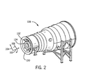
- FIG. 2 illustrates a perspective view of an embodiment of a gas turbine exhaust diffuser 128.
- the struts 132 are disposed around a hub 134 (e.g., inner wall) and extend radially 104 from the hub 134.
- the struts 132 are coupled between the hub 134 and the outer wall 130 and thereby structurally support the outer wall 130.
- the outer wall 130 encompasses the hub 134.
- the outer wall 130 may be configured to expand or contract to alter the circumference of the outer wall 130.
- turbine exhaust flows into the exhaust diffuser 128, the exhaust flows between the hub 134 and the outer wall 130.
- the exhaust flows around the struts 132 and the struts 132 alter the exhaust flow.
- the properties of how the exhaust flows through the exhaust diffuser 128 are affected by the shape and position of the struts 132. For example, in certain struts 132, flow separation may occur at different portions of the struts 132. However, the techniques described below may be used to decrease flow separation.
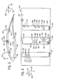
- FIG. 3 is a cross-sectional view of an embodiment of the strut 132 of FIG. 2 with moveable plates that can be used to decrease flow separation.
- the strut 132 is illustrated as having a generally elongated tear drop shape. Such a configuration may minimize flow disturbances that the strut 132 causes to the exhaust flowing through the diffuser section 128 when the turbine engine 100 is operating under full load conditions.
- An exterior portion 136 of the strut 132 forms the visible tear drop shape while an interior portion 138 is hollow. Further, the exterior portion 136 has an outer surface 140 and an inner surface 142.
- Openings 144, 146, 148, and 150 extend from the outer surface 140 to the inner surface 142 and permit fluid (e.g., exhaust, air, etc) to flow through the openings 144, 146, 148, and 150, between the interior portion 138 and the exterior portion 136 of the strut 132 (e.g., fluid to flow from the interior portion 138, through the openings 144, 146, 148, and 150, to exit the strut 132).
- the openings 144, 146, 148, and 150 may each include multiple openings at various locations along the surface of the strut 132.
- a fluid may be injected into the interior portion 138 of the strut 132 (e.g., using a pump).
- the injected fluid may exit the strut 132 through openings 144, 146, 148, and 150 and may alter the flow of the exhaust flowing around the strut 132. For example, it may be desirable to allow fluid to flow through openings 144 during startup of the turbine engine 100 to improve the profile of exhaust flowing around the strut 132. Conversely, it may be desirable to inhibit fluid flow through any of the openings 144, 146, 148, and 150 when the turbine engine 100 is operating at full capacity. As may be appreciated, depending on the operational state of the turbine engine 100, disturbances to the exhaust flow caused by the strut 132 may be decreased when fluid is injected into the strut 132 and the injected fluid flows through at least one of the openings 144, 146, 148, and 150. For example, injected fluid may stop flow separation from occurring at various locations on the strut 132 depending on the operational state of the turbine engine 100 and whether fluid flow through the openings 144, 146, 148, and 150 is blocked or enabled.
- a first moveable plate 152 is disposed in a first strut region 153.
- the first moveable plate 152 is coupled to the strut 132 and may be moved to increase or decrease fluid flow through the openings 144.
- a second moveable plate 154 is disposed in a second strut region 155.
- the second moveable plate 154 is coupled to the strut 132 and may be moved to increase or decrease fluid flow through the openings 146 and 148.
- a third moveable plate 156 is disposed in a third strut region 157. The third moveable plate 156 is coupled to the strut 132 and may be moved to increase or decrease fluid flow through the openings 150.
- the moveable plates may control the amount of fluid flowing through respective openings 144, 146, 148, and 150.
- the moveable plates 152, 154, and 156 are coupled to the inner surface 142 of the strut 132.
- the moveable plates 152, 154, and 156 may be coupled to the outer surface 140 of the strut 132 (i.e., on the outside of the strut 132).
- the moveable plates 152, 154, and 156 may be constructed of any material, such as a metal, polymer, and so forth.
- the moveable plates 152, 154, and 156 may be constructed of a shape memory alloy.
- the moveable plates 152, 154, and 156 may be constructed of a shape memory alloy formed using one or more of the following: copper, zinc, aluminum, nickel, titanium, gold, and iron.
- the shape memory alloy may be used to control the amount of fluid that flows through the openings 144, 146, 148, and 150 based on a temperature or some other characteristic of the alloy.
- the shape memory alloy may thermally expand or contract based on the temperature of the strut 132 and/or the exhaust flowing through the gas turbine exhaust diffuser 128. As such, the shape memory alloy changes shape during operation to control the amount of fluid flow.
- the openings 144, 146, 148, and 150 may be arranged in one or more of the axial direction 102 (as shown), the radial direction 104, and/or the circumferential direction 106 to allow fluid to flow from the interior portion 138 of the strut 132 to the exterior portion 140.
- FIG. 4 is a cross-sectional side view of one embodiment of the strut 132 with moveable plates, as illustrated in FIG. 3 .
- the inner surface 142 is shown with the plates 152, 154, and 156 coupled to it.
- the first moveable plate 152 has openings 170, 172, 174, and 176. As illustrated, the openings 170, 172, 174, and 176 in the plate 152 are aligned with openings 144 in the strut 132.
- fluid may flow through the strut exterior 136. Further, the plate 152 may be moved in the axial direction 102 as shown by arrow 178.
- a small amount of movement of the plate 152 may partially block the openings 144, while a larger amount of movement of the plate 152 may completely block the openings 144.
- the plate 152 may be moved to either side (axially) to block the openings 144.
- the plate 152 may be moved between various positions to control the amount of fluid flowing through the openings 144. Specifically, the plate 152 may be positioned as illustrated so the openings 144 are completely open, the plate 152 may be positioned so the openings 144 are completely closed, or the plate 152 may be positioned at any location in between so the openings 144 are partially open.
- the second moveable plate 154 has openings 180, 182, 184, 186, 188, 190, 192, and 194. Some of the openings 180, 182, 192, and 194 do not align with the openings 146 and 148 in the strut 132. Conversely, other openings 184, 186, 188, and 190 do align with the openings 146 and 148 in the strut 132. Some openings 146 and 148 in the strut 132 are illustrated with dashed lines because they do not align with an opening in the plate 154 as the plate 154 is currently positioned.
- the openings 180, 182, 184, 186, 188, 190, 192, and 194 of the plate 154 may move to align with the currently unaligned openings 146 and 148.
- the plate 154 may move to the right and the openings 184 and 186 of the plate 154 may align with the openings 148 in the strut 132, while the openings 180 and 182 of the plate 154 may align with the openings 146 in the strut 132.
- the plate 154 may move to the left and the openings 188 and 190 of the plate 154 may align with the openings 146 in the strut 132, while the openings 192 and 194 of the plate 154 may align with the openings 148 in the strut 132.
- the third moveable plate 156 has openings 198, 200, 202, and 204.
- One opening 202 does not align with the openings 150 in the strut 132, while the other openings 198, 200, and 204 do align with the openings 150 in the strut 132.
- the plate 156 may be moved in the axial direction 102 as shown by arrow 206. Moving the plate 156 may cause the opening 202 of the plate 156 to move to align with one of the openings 150 and may cause the openings 198, 200, and 204 to move to not be aligned with one of the openings 150.
- two of the openings 150 at the top of the plate 156 may not be aligned with any opening in the plate 156, even if the plate is moved in the axial direction 102. It should be noted that in certain embodiments, the plates 152, 154, and 156 may move in the radial direction 104 and/or the circumferential direction 106 to control fluid flow through the openings 144, 146, 148, and 150.
- the openings 144, 146, 148, and 150 may have a diameter of any suitable size.
- the diameter of the openings 144, 146, 148, and 150 may be approximately 5, 10, 15, 20, 25, 30, 40, or 50 mm.
- the openings 144, 146, 148, and 150 may have a diameter of approximately 6 to 30 mm, 22 to 60 mm, or 12 to 45 mm.
- the openings 144, 146, 148, and 150 may be circular, oval, square, rectangular, triangular, or any other suitable shape.
- the openings in the plates 152, 154, and 156 may also be any suitable size or shape.
- the openings in the plates 152, 154, and 156 may not be the same shapes as the openings 144, 146, 148, and 150.
- the openings 144, 146, 148, and 150 may be circular and the openings in the plates 152, 154, and 156 may vary between different parts of a circle, such as a half-circle, crescent shape, pie shape, etc.
- the openings in the plates 152, 154, and 156 may be the same shapes and/or sizes as the openings 144, 146, 148, and 150.
- the arrangement of the openings in each of the plates 152, 154, and 156 may be different on each plate, as illustrated, or the openings on each plate may be uniform.
- the arrangement illustrated in FIG. 4 is meant to demonstrate that the openings may be in any suitable position based on the particular application.
- the arrangement of the openings e.g., pattern and location of the openings
- number of the openings e.g., number of the openings
- size of the openings e.g., size of the openings, and shape of the openings may be determined based on the operational requirements for a particular turbine engine 100.
- the fluid flowing from the strut interior 138 through the openings 144, 146, 148, and 150 may be altered. In various situations, it may be desirable to allow fluid to flow through all, some, or none of the openings 144, 146, 148, and 150 in order to stop flow separation from occurring. For example, when the turbine engine 100 is operating at approximately full load capacity (e.g., approximately 100 percent capacity), it may be desirable to block fluid from flowing through all of the openings 144, 146, 148, and 150 so that the flow of exhaust around the struts 132 is not disturbed (e.g., the struts 132 may be designed for minimal flow separation when operating at full load capacity).
- approximately full load capacity e.g., approximately 100 percent capacity
- the turbine engine 100 when the turbine engine 100 is operating at approximately 40 to 100 percent load capacity, it may be desirable to allow fluid to flow through openings 150 to alter the exhaust flow around the struts 132 and stop flow separation that may occur in the third strut region 157 without the fluid flowing through openings 150.
- openings 146 and/or 148 when the turbine engine 100 is operating at approximately 20 to 50 percent load capacity, it may be desirable to allow fluid to flow through two of the openings, for example, openings 146 and/or 148, to inhibit flow separation from occurring in the second strut region 155. Further, when the turbine engine 100 is operating at approximately 0 to 30 percent load capacity, it may be desirable to allow fluid to flow through opening 144 to inhibit flow separation from occurring in the first strut region 153. Further it may be desirable to allow fluid to flow through openings 144 during startup of the turbine engine 100. As may be appreciated, the specifics of which openings 144, 146, 148, and 150 will provide desired fluid flow through the exhaust diffuser section 128 may vary between systems and may depend on the particular application.
- the plates 152, 154, and 156 may be moved in any manner to control the fluid flow through the openings 144, 146, 148, and 150 in the strut 132.
- the plates 152, 154, and 156 may be moved by an actuation system to control the fluid flow.
- the actuation system may include hydraulically, pneumatically, mechanically, or electrically operated actuators.
- the plates 152, 154, and 156 may be moved to control fluid flow based on a schedule, operational parameters, sensor measurements, and so forth.
- the plates 152, 154, and 156 may be moved to allow or inhibit fluid flow based on a timed schedule where during specific time periods of operation, fluid may flow through specific openings 144, 146, 148, and 150.
- the timed periods may be correlated to the turbine engine 100 starting, stopping, or operating for a specific period of time.
- the plates 152, 154, and 156 may be configured to move based on an operational parameter of the turbine engine 100, such as the operating load capacity as previously described.
- the plates 152, 154, and 156 may be configured to move based on sensor measurements, such as temperature sensors, flow sensors, operational state sensors, pressure sensors, etc.
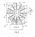
- FIG. 5 is a block diagram of a gas turbine exhaust diffuser system 220 having a control system 222 for use in conjunction with moveable plates 224.
- the moveable plates 224 in each strut may include any number of plates that are used to control fluid flow through the struts 132.
- the moveable plates 224 may each have a lever or some other attachment that couples the plates 224 to a device for moving the plates 224.
- the control system 222 includes a controller 226 that may be configured to send (or transmit) control signals to actuators 228. The control signals may cause the actuators 228 to move the plates 224 to desired positions and, thus, alter the fluid flow through the struts 132.
- the controller 226 may be a computer, an expansion card for a computer, a stand-alone computing device, a microprocessor, an integrated circuit (e.g., programmable logic controller (PLC)), and so forth.
- the actuators 228 may be any type of actuator, such as a hydraulic, pneumatic, mechanical (e.g., rack and pinion), or electrical actuator.
- the control system 222 includes actuator wiring 228 for transmitting control signals to the actuators 228.
- certain embodiments may not include actuator wiring and instead may include hydraulic and/or pneumatic circuitry for controlling the actuators 228.
- the controller 226 may also be configured to receive signals from sensors 232 that provide an indication of a sensed parameter.
- the sensors 232 may provide an indication of an operational state of the turbine engine 100, a temperature, an amount of fluid flow, and/or a fluid pressure. Further, the sensors 232 may provide any measurement that can be used by the controller 226 to determine when to move the plates 224.
- the sensors 232 are communicatively coupled to the controller 226 using wires 234. As illustrated, the sensors 232 may be coupled directly to the struts 132, or in other embodiments, the sensors 232 may be placed in any suitable location.
- the sensors 232 may be located at the front edge of the struts 132 (e.g., the location that first contacts the exhaust flow), back edge of the struts 132 (e.g., the location that has final contact with the exhaust flow), within the struts 132 to be flush with the struts 132 (e.g., to cause minimal disturbance to the exhaust flow), in or on the outer wall 130, and/or in or on the hub 134.
- the techniques described herein may enable the use of strut fluidics in the exhaust diffuser system 220. Specifically, fluid flow separation may be decreased by moving plates to cover or open holes in the struts. Therefore, the turbine engine 100 may have performance gains during part load operation. Further, the operation of the turbine engine 100 during full load operation may be impacted minimally, if at all, by using such techniques.
Landscapes
- Engineering & Computer Science (AREA)
- Mechanical Engineering (AREA)
- General Engineering & Computer Science (AREA)
- Control Of Turbines (AREA)
- Structures Of Non-Positive Displacement Pumps (AREA)
Abstract
A system and device for controlling fluid flow through a gas turbine exhaust. One gas turbine exhaust may include a strut (132) of the gas turbine exhaust having a first opening (144) configured to permit a fluid to flow between an interior portion (138) of the strut and an exterior portion (136) of the strut. The gas turbine exhaust also may include a moveable plate (152) coupled to the strut (132) and configured to control an amount of the fluid flowing through the first opening (144).
Description
- The subject matter disclosed herein relates generally to turbine engines and, more specifically, to controlling fluid flow through a gas turbine exhaust.
- A gas turbine system may include an exhaust diffuser coupled to a gas turbine engine. The gas turbine engine combusts a mixture of fuel and air to generate hot combustion gases, which in turn drive one or more turbines. In particular, the hot combustion gases force turbine blades to rotate, thereby driving a shaft to rotate one or more loads, e.g., electrical generator. The exhaust diffuser receives the exhaust from the turbine, and gradually reduces the pressure and velocity. Within the exhaust diffuser, struts provide structural support but may alter characteristics of the exhaust flow by causing disturbances in the flow. However, the struts may be designed to cause minimal disturbance with the exhaust flow when the turbine engine is operating under full load conditions. Unfortunately, such struts may cause disturbances in exhaust flow when the turbine engine is operating under partial load conditions.
- Certain embodiments commensurate in scope with the originally claimed invention are summarized below. These embodiments are not intended to limit the scope of the claimed invention, but rather these embodiments are intended only to provide a brief summary of possible forms of the invention. Indeed, the invention may encompass a variety of forms that may be similar to or different from the embodiments set forth below.
- In a first aspect, a gas turbine exhaust includes a strut of the gas turbine exhaust having a first opening configured to permit a fluid to flow between an interior portion of the strut and an exterior portion of the strut. The gas turbine exhaust also includes a moveable plate coupled to the strut and configured to control an amount of the fluid flowing through the first opening.
- In a second aspect, a control system to a gas turbine exhaust diffuser includes a controller configured to receive a signal indicating an operational state of a gas turbine engine. The controller is also configured to transmit a control signal to an actuator. The control signal causes the actuator to move a plate coupled to a strut located in the gas turbine exhaust diffuser to alter fluid flow through the strut.
- In a third aspect, a gas turbine exhaust diffuser includes an inner wall forming a hub and an outer wall encompassing the inner wall. The exhaust diffuser also includes a plurality of struts coupled between the inner wall and the outer wall of the gas turbine exhaust diffuser. Each strut includes at least one opening and a movable plate configured to control fluid flow through the at least one opening.
- Embodiments of the present invention will now be described, by way of example only, with reference to the accompanying drawings in which:
-
FIG. 1 is a cross-sectional side view of a gas turbine engine in accordance with an embodiment of the present technique; -
FIG. 2 is a perspective view of an embodiment of a gas turbine exhaust diffuser usable with the gas turbine engine ofFIG. 1 ; -
FIG. 3 is a cross-sectional view of an embodiment of a strut of the gas turbine exhaust diffuser ofFIG. 2 with movable plates; -
FIG. 4 is a cross-sectional side view of an embodiment of the strut with movable plates, as illustrated inFIG. 3 ; and -
FIG. 5 is a block diagram of a gas turbine exhaust diffuser system, usable with the gas turbine engine ofFIG. 1 , having a control system for use in conjunction with movable plates, in accordance with an embodiment of the present technique. - One or more specific embodiments of the present invention will be described below. In an effort to provide a concise description of these embodiments, all features of an actual implementation may not be described in the specification. It should be appreciated that in the development of any such actual implementation, as in any engineering or design project, numerous implementation-specific decisions must be made to achieve the developers' specific goals, such as compliance with system-related and business-related constraints, which may vary from one implementation to another. Moreover, it should be appreciated that such a development effort might be complex and time consuming, but would nevertheless be a routine undertaking of design, fabrication, and manufacture for those of ordinary skill having the benefit of this disclosure.
- When introducing elements of various embodiments of the present invention, the articles "a," "an," "the," and "said" are intended to mean that there are one or more of the elements. The terms "comprising," "including," and "having" are intended to be inclusive and mean that there may be additional elements other than the listed elements.
- In a turbine system, struts may be used to provide structural support to the turbine exhaust system. However, in some systems, the struts may cause disturbances in exhaust flow. As discussed below, certain embodiments of a gas turbine exhaust include struts with openings to permit a fluid (e.g., exhaust) to flow from an interior of each strut to an exterior of each strut to decrease exhaust flow disturbances. To control the amount of fluid flowing between the exterior and the interior of the struts, moveable plates may be coupled to the struts and moved between various positions to increase or decrease fluid flow depending on the amount of fluid flow desired to decrease exhaust flow disturbances. For example, the moveable plates may cover openings in the struts to decrease fluid flow through the struts and the moveable plates may uncover openings in the struts to increase fluid flow through the struts. Controlling the fluid flow through the struts may decrease disturbances in the exhaust flowing around the struts (e.g., decrease flow separation).
- In one embodiment, the moveable plates may be moved between various positions using an actuation system. The actuation system may move the plates based on the operating load capacity of the gas turbine. For example, the actuation system may move the plates to cover openings in the struts during full operating load capacity (e.g., 100 percent capacity) so that fluid does not flow through the struts (e.g., to have minimal exhaust flow disturbance). Further, the actuation system may move the plates to uncover openings in the struts during less than full operating load capacity (e.g., less than 100 percent capacity) so that fluid flows through the struts (e.g., to alter the exhaust flow to have minimal exhaust flow disturbance).
- In another embodiment, the actuation system may move the plates based on sensor measurements and/or a schedule. For example, when sensor measurements pass a certain threshold, the plates may increase or decrease the amount of fluid flowing through the struts. Further, the plates may be moved to different positions based on time periods elapsing. For example, after a first time period elapses the plates may increase fluid flow through the struts and after a second time period elapses the plates may decrease fluid flow through the struts.
- Additionally, a controller may be utilized to control the movement of the plates along the struts. For example, the controller may receive signals from one or more sensors that indicate fluid flow parameters or other attributes of the exhaust system. These signals may be utilized by the controller to determine what control signals are to be transmitted to control, for example, the actuation system for moving the plates.
- Turning now to the drawings and referring first to
FIG. 1 , an embodiment of agas turbine engine 100 is illustrated. Thegas turbine engine 100 extends in anaxial direction 102. Aradial direction 104 illustrates a direction extending outward from the axis of theengine 100. Further, acircumferential direction 106 illustrates the rotational direction around the axis of theengine 100. Thegas turbine engine 100 includes one ormore fuel nozzles 108 located inside acombustor section 110. In certain embodiments, thegas turbine engine 100 may includemultiple combustors 112 disposed in an annular (e.g., circumferential 106) arrangement within thecombustor section 110. Further, eachcombustor 112 may includemultiple fuel nozzles 108 attached to or near the head end of eachcombustor 112 in an annular (e.g., circumferential 106) or other arrangement. - Air enters through an
air intake section 114 and is compressed by acompressor 116. The compressed air from thecompressor 116 is then directed into thecombustor section 110 where the compressed air is mixed with fuel. The mixture of compressed air and fuel is generally burned within thecombustor section 110 to generate high-temperature, high-pressure combustion gases, which are used to generate torque within aturbine section 118. As noted above,multiple combustors 112 may be annularly (e.g., circumferentially 106) disposed within thecombustor section 110. Eachcombustor 112 includes atransition piece 119 that directs the hot combustion gases from thecombustor 112 to theturbine section 118. In particular, eachtransition piece 119 generally defines a hot gas path from thecombustor 112 to a nozzle assembly of theturbine section 118. As depicted, theturbine section 118 includesmultiple blades 120 coupled to arotor wheel 122 rotatably attached to ashaft 124. Theturbine section 118 also includes a nozzle assembly 126 disposed directly upstream of each set ofblades 120. The nozzle assemblies 126 direct the hot combustion gases toward theblades 120 where the hot combustion gases apply motive forces to theblades 120 to rotate theblades 120, thereby turning theshaft 124. Theblades 120 andshaft 124 rotate in thecircumferential direction 106. The hot combustion gases may then exit thegas turbine section 118 into anexhaust diffuser section 128. Theexhaust diffuser section 128 reduces the velocity of fluid flow and also increases the static pressure to increase the work produced by thegas turbine engine 100. Anouter wall 130 extends axially 102 along the length of theexhaust diffuser section 128. Astrut 132 is illustrated abutting theouter wall 130. Further, although only onestrut 132 is illustrated in this cross-sectional view,multiple struts 132 are used as support structures between theouter wall 130 and an inner wall (e.g., a hub extending circumferentially 106 at a base of the struts 132) of theexhaust diffuser section 128. -
FIG. 2 illustrates a perspective view of an embodiment of a gasturbine exhaust diffuser 128. In particular, thestruts 132 are disposed around a hub 134 (e.g., inner wall) and extend radially 104 from thehub 134. Thestruts 132 are coupled between thehub 134 and theouter wall 130 and thereby structurally support theouter wall 130. As may be appreciated, theouter wall 130 encompasses thehub 134. In certain embodiments, theouter wall 130 may be configured to expand or contract to alter the circumference of theouter wall 130. When turbine exhaust flows into theexhaust diffuser 128, the exhaust flows between thehub 134 and theouter wall 130. Thus, the exhaust flows around thestruts 132 and thestruts 132 alter the exhaust flow. Therefore, the properties of how the exhaust flows through theexhaust diffuser 128 are affected by the shape and position of thestruts 132. For example, incertain struts 132, flow separation may occur at different portions of thestruts 132. However, the techniques described below may be used to decrease flow separation. -
FIG. 3 is a cross-sectional view of an embodiment of thestrut 132 ofFIG. 2 with moveable plates that can be used to decrease flow separation. Thestrut 132 is illustrated as having a generally elongated tear drop shape. Such a configuration may minimize flow disturbances that thestrut 132 causes to the exhaust flowing through thediffuser section 128 when theturbine engine 100 is operating under full load conditions. Anexterior portion 136 of thestrut 132 forms the visible tear drop shape while aninterior portion 138 is hollow. Further, theexterior portion 136 has anouter surface 140 and aninner surface 142.Openings outer surface 140 to theinner surface 142 and permit fluid (e.g., exhaust, air, etc) to flow through theopenings interior portion 138 and theexterior portion 136 of the strut 132 (e.g., fluid to flow from theinterior portion 138, through theopenings openings strut 132. During operation, a fluid may be injected into theinterior portion 138 of the strut 132 (e.g., using a pump). The injected fluid may exit thestrut 132 throughopenings strut 132. For example, it may be desirable to allow fluid to flow throughopenings 144 during startup of theturbine engine 100 to improve the profile of exhaust flowing around thestrut 132. Conversely, it may be desirable to inhibit fluid flow through any of theopenings turbine engine 100 is operating at full capacity. As may be appreciated, depending on the operational state of theturbine engine 100, disturbances to the exhaust flow caused by thestrut 132 may be decreased when fluid is injected into thestrut 132 and the injected fluid flows through at least one of theopenings strut 132 depending on the operational state of theturbine engine 100 and whether fluid flow through theopenings - A first
moveable plate 152 is disposed in afirst strut region 153. The firstmoveable plate 152 is coupled to thestrut 132 and may be moved to increase or decrease fluid flow through theopenings 144. Further, a secondmoveable plate 154 is disposed in asecond strut region 155. The secondmoveable plate 154 is coupled to thestrut 132 and may be moved to increase or decrease fluid flow through theopenings moveable plate 156 is disposed in athird strut region 157. The thirdmoveable plate 156 is coupled to thestrut 132 and may be moved to increase or decrease fluid flow through theopenings 150. Thus, based on the position of themoveable plates respective openings moveable plates inner surface 142 of thestrut 132. However, in certain embodiments, themoveable plates outer surface 140 of the strut 132 (i.e., on the outside of the strut 132). - The
moveable plates moveable plates moveable plates openings strut 132 and/or the exhaust flowing through the gasturbine exhaust diffuser 128. As such, the shape memory alloy changes shape during operation to control the amount of fluid flow. It should be noted that in certain embodiments, theopenings radial direction 104, and/or thecircumferential direction 106 to allow fluid to flow from theinterior portion 138 of thestrut 132 to theexterior portion 140. -
FIG. 4 is a cross-sectional side view of one embodiment of thestrut 132 with moveable plates, as illustrated inFIG. 3 . Theinner surface 142 is shown with theplates moveable plate 152 hasopenings openings plate 152 are aligned withopenings 144 in thestrut 132. Thus, with the firstmoveable plate 152 in its illustrated position, fluid may flow through thestrut exterior 136. Further, theplate 152 may be moved in theaxial direction 102 as shown byarrow 178. As may be appreciated, a small amount of movement of theplate 152 may partially block theopenings 144, while a larger amount of movement of theplate 152 may completely block theopenings 144. Further, theplate 152 may be moved to either side (axially) to block theopenings 144. Thus, theplate 152 may be moved between various positions to control the amount of fluid flowing through theopenings 144. Specifically, theplate 152 may be positioned as illustrated so theopenings 144 are completely open, theplate 152 may be positioned so theopenings 144 are completely closed, or theplate 152 may be positioned at any location in between so theopenings 144 are partially open. - The second
moveable plate 154 hasopenings openings openings strut 132. Conversely,other openings openings strut 132. Someopenings strut 132 are illustrated with dashed lines because they do not align with an opening in theplate 154 as theplate 154 is currently positioned. However, when theplate 154 is moved in theaxial direction 102 as shown byarrow 196, theopenings plate 154 may move to align with the currentlyunaligned openings plate 154 may move to the right and theopenings plate 154 may align with theopenings 148 in thestrut 132, while theopenings plate 154 may align with theopenings 146 in thestrut 132. Further, theplate 154 may move to the left and theopenings plate 154 may align with theopenings 146 in thestrut 132, while theopenings plate 154 may align with theopenings 148 in thestrut 132. - The third
moveable plate 156 hasopenings opening 202 does not align with theopenings 150 in thestrut 132, while theother openings openings 150 in thestrut 132. Like theother plates plate 156 may be moved in theaxial direction 102 as shown byarrow 206. Moving theplate 156 may cause theopening 202 of theplate 156 to move to align with one of theopenings 150 and may cause theopenings openings 150. Further, two of theopenings 150 at the top of theplate 156 may not be aligned with any opening in theplate 156, even if the plate is moved in theaxial direction 102. It should be noted that in certain embodiments, theplates radial direction 104 and/or thecircumferential direction 106 to control fluid flow through theopenings - The
openings openings openings openings plates plates openings openings plates plates openings plates FIG. 4 is meant to demonstrate that the openings may be in any suitable position based on the particular application. For example, the arrangement of the openings (e.g., pattern and location of the openings), number of the openings, size of the openings, and shape of the openings may be determined based on the operational requirements for aparticular turbine engine 100. - It should be noted that by moving the
plates strut interior 138 through theopenings openings turbine engine 100 is operating at approximately full load capacity (e.g., approximately 100 percent capacity), it may be desirable to block fluid from flowing through all of theopenings struts 132 is not disturbed (e.g., thestruts 132 may be designed for minimal flow separation when operating at full load capacity). Further, when theturbine engine 100 is operating at approximately 40 to 100 percent load capacity, it may be desirable to allow fluid to flow throughopenings 150 to alter the exhaust flow around thestruts 132 and stop flow separation that may occur in thethird strut region 157 without the fluid flowing throughopenings 150. - In addition, when the
turbine engine 100 is operating at approximately 20 to 50 percent load capacity, it may be desirable to allow fluid to flow through two of the openings, for example,openings 146 and/or 148, to inhibit flow separation from occurring in thesecond strut region 155. Further, when theturbine engine 100 is operating at approximately 0 to 30 percent load capacity, it may be desirable to allow fluid to flow throughopening 144 to inhibit flow separation from occurring in thefirst strut region 153. Further it may be desirable to allow fluid to flow throughopenings 144 during startup of theturbine engine 100. As may be appreciated, the specifics of whichopenings exhaust diffuser section 128 may vary between systems and may depend on the particular application. - The
plates openings strut 132. For example, theplates plates plates specific openings turbine engine 100 starting, stopping, or operating for a specific period of time. In addition, theplates turbine engine 100, such as the operating load capacity as previously described. Further, theplates -
FIG. 5 is a block diagram of a gas turbineexhaust diffuser system 220 having acontrol system 222 for use in conjunction withmoveable plates 224. As may be appreciated, themoveable plates 224 in each strut may include any number of plates that are used to control fluid flow through thestruts 132. Further, themoveable plates 224 may each have a lever or some other attachment that couples theplates 224 to a device for moving theplates 224. Thecontrol system 222 includes acontroller 226 that may be configured to send (or transmit) control signals toactuators 228. The control signals may cause theactuators 228 to move theplates 224 to desired positions and, thus, alter the fluid flow through thestruts 132. In certain embodiments, thecontroller 226 may be a computer, an expansion card for a computer, a stand-alone computing device, a microprocessor, an integrated circuit (e.g., programmable logic controller (PLC)), and so forth. As previously discussed, theactuators 228 may be any type of actuator, such as a hydraulic, pneumatic, mechanical (e.g., rack and pinion), or electrical actuator. Thecontrol system 222 includesactuator wiring 228 for transmitting control signals to theactuators 228. However, as may be appreciated, certain embodiments may not include actuator wiring and instead may include hydraulic and/or pneumatic circuitry for controlling theactuators 228. - The
controller 226 may also be configured to receive signals fromsensors 232 that provide an indication of a sensed parameter. For example, thesensors 232 may provide an indication of an operational state of theturbine engine 100, a temperature, an amount of fluid flow, and/or a fluid pressure. Further, thesensors 232 may provide any measurement that can be used by thecontroller 226 to determine when to move theplates 224. Thesensors 232 are communicatively coupled to thecontroller 226 usingwires 234. As illustrated, thesensors 232 may be coupled directly to thestruts 132, or in other embodiments, thesensors 232 may be placed in any suitable location. For example, thesensors 232 may be located at the front edge of the struts 132 (e.g., the location that first contacts the exhaust flow), back edge of the struts 132 (e.g., the location that has final contact with the exhaust flow), within thestruts 132 to be flush with the struts 132 (e.g., to cause minimal disturbance to the exhaust flow), in or on theouter wall 130, and/or in or on thehub 134. - As may be appreciated, the techniques described herein may enable the use of strut fluidics in the
exhaust diffuser system 220. Specifically, fluid flow separation may be decreased by moving plates to cover or open holes in the struts. Therefore, theturbine engine 100 may have performance gains during part load operation. Further, the operation of theturbine engine 100 during full load operation may be impacted minimally, if at all, by using such techniques. - This written description uses examples to disclose the invention, including the best mode, and also to enable any person skilled in the art to practice the invention, including making and using any devices or systems and performing any incorporated methods. The patentable scope of the invention is defined by the claims, and may include other examples that occur to those skilled in the art. Such other examples are intended to be within the scope of the claims if they have structural elements that do not differ from the literal language of the claims, or if they include equivalent structural elements with insubstantial differences from the literal languages of the claims.
Claims (15)
- A gas turbine exhaust comprising:a strut (132) of the gas turbine exhaust having a first opening (144) configured to permit a fluid to flow between an interior portion (138) of the strut (132) and an exterior portion (136) of the strut (132); anda moveable plate (152) coupled to the strut (132) and configured to control an amount of the fluid flowing through the first opening (144).
- The gas turbine exhaust of claim 1, wherein the movable plate (152) is coupled to one of an inner surface (142) of the strut (132) or an outer surface (140) of the strut (132).
- The gas turbine exhaust of claim 1 or 2, wherein the moveable plate (152) comprises a shape memory alloy.
- The gas turbine exhaust of any of claims 1 to 3, wherein the movable plate (152) is configured to be moved between at least two positions to control the amount of the fluid flowing through the first opening (144).
- The gas turbine exhaust of claim 4, wherein the moveable plate (152) is configured to be moved between the at least two positions based on a received signal.
- The gas turbine exhaust of claim 4 or 5, wherein the moveable plate (152) is configured to be moved to a first position to inhibit fluid flow through the first opening (144) when a gas turbine is at full load operation and configured to be moved to a second position to allow fluid flow through the first opening (144) during the gas turbine startup.
- The gas turbine exhaust of any preceding claim, comprising a second movable plate (154) configured to alter fluid flow through a second opening (180) in the strut (132) during a gas turbine (100) startup, wherein the second opening (180) is in a first strut region (153).
- The gas turbine exhaust of claim 7, comprising a third movable plate (156) configured to alter fluid flow through a third opening (198) in the strut (132) during operation of a gas turbine (100), wherein the third opening (198) is in a second strut region (155) and the third movable plate (156) is configured to be moved when the gas turbine (100) is operating between approximately 20 and 50 percent load capacity.
- The gas turbine exhaust of claim 8, wherein the first opening (144) is in a third strut region (157) and the movable plate (152) is configured to be moved when the gas turbine (100) is operating between approximately 40 and 100 percent load capacity.
- A control system to a gas turbine exhaust diffuser comprising:a controller (226) configured to:receive a signal indicating an operational state of a gas turbine engine (100); andtransmit a control signal to an actuator (228), wherein the control signal causes the actuator (228) to move a plate (144) coupled to a strut (132) located in the gas turbine exhaust diffuser (220) to alter fluid flow through the strut (132).
- The control system of claim 10, comprising a sensor (232) configured to produce the signal indicating the operational state of the gas turbine engine (100).
- The control system of claim 11, wherein the sensor (232) is a temperature sensor.
- The control system of any of claims 10 to 12, wherein the actuator (228) comprises one of a hydraulic actuator or a pneumatic actuator.
- The control system of any of claims 10 to 13, wherein the controller is arranged to control the actuator to move the plate (152) so as to control fluid flow based on one of a schedule, operational parameters or sensor measurements.
- A gas turbine exhaust diffuser (128) comprising:an inner wall forming a hub (134);an outer wall (130) encompassing the inner wall;a plurality of struts (132) coupled between the inner wall and the outer wall (130) of the gas turbine exhaust diffuser (128), wherein each strut (132) comprises at least one opening (144) and a movable plate (152) configured to control fluid flow through the at least one opening (144).
Applications Claiming Priority (1)
| Application Number | Priority Date | Filing Date | Title |
|---|---|---|---|
| US13/344,422 US20130174534A1 (en) | 2012-01-05 | 2012-01-05 | System and device for controlling fluid flow through a gas turbine exhaust |
Publications (1)
| Publication Number | Publication Date |
|---|---|
| EP2613024A2 true EP2613024A2 (en) | 2013-07-10 |
Family
ID=47678496
Family Applications (1)
| Application Number | Title | Priority Date | Filing Date |
|---|---|---|---|
| EP12198570.9A Withdrawn EP2613024A2 (en) | 2012-01-05 | 2012-12-20 | System and device for controlling fluid flow through a gas turbine exhaust |
Country Status (5)
| Country | Link |
|---|---|
| US (1) | US20130174534A1 (en) |
| EP (1) | EP2613024A2 (en) |
| JP (1) | JP2013139802A (en) |
| CN (1) | CN103195580A (en) |
| RU (1) | RU2012158347A (en) |
Cited By (1)
| Publication number | Priority date | Publication date | Assignee | Title |
|---|---|---|---|---|
| WO2015065672A1 (en) * | 2013-10-30 | 2015-05-07 | Siemens Aktiengesellschaft | Gas turbine diffuser strut including coanda flow injection |
Families Citing this family (13)
| Publication number | Priority date | Publication date | Assignee | Title |
|---|---|---|---|---|
| EP2634381A1 (en) * | 2012-02-28 | 2013-09-04 | Siemens Aktiengesellschaft | Gas turbine with an exhaust gas diffuser and support ribs |
| US9644497B2 (en) * | 2013-11-22 | 2017-05-09 | Siemens Energy, Inc. | Industrial gas turbine exhaust system with splined profile tail cone |
| US10255406B2 (en) * | 2015-02-24 | 2019-04-09 | Siemens Corporation | Designing the geometry of a gas turbine exhaust diffuser on the basis of fluid dynamics information |
| CN106014489B (en) * | 2016-07-15 | 2018-01-02 | 中国科学院工程热物理研究所 | Turbo blade with cooling structure and apply its gas turbine |
| US10794289B2 (en) | 2016-08-09 | 2020-10-06 | General Electric Company | Modulated turbine component cooling |
| US11085372B2 (en) * | 2018-07-18 | 2021-08-10 | The Boeing Company | Anti-ice system exhaust air disruptor |
| KR101993700B1 (en) * | 2018-09-07 | 2019-06-27 | 주식회사 이엠코 | Apparatus for treating exhaust gas of thermal plant |
| KR102086440B1 (en) * | 2019-05-31 | 2020-03-09 | 주식회사 이엠코 | Apparatus for treating exhaust gas of thermal plant |
| KR102236239B1 (en) * | 2019-05-31 | 2021-04-05 | 주식회사 이엠코 | Composition for reducing yellow plume, Method of reducing yellow plume, Apparatus for reducing yellow plume |
| US12286888B1 (en) | 2023-12-22 | 2025-04-29 | Ge Infrastructure Technology Llc | Mitigation of rotating stall in turbine section using outer flow control vanes |
| US12428973B2 (en) | 2023-12-22 | 2025-09-30 | Ge Infrastructure Technology Llc | Mitigation of rotating stall in turbine exhaust section using segmented auxiliary struts |
| US12338776B1 (en) * | 2023-12-22 | 2025-06-24 | Ge Infrastructure Technology Llc | Fluid injection system and method for mitigating rotating stall in turbine engine |
| US12221896B1 (en) | 2023-12-22 | 2025-02-11 | Ge Infrastructure Technology Llc | Mitigation of rotating stall in turbine exhaust section using inner flow control vanes |
Family Cites Families (11)
| Publication number | Priority date | Publication date | Assignee | Title |
|---|---|---|---|---|
| DE1923150A1 (en) * | 1968-05-08 | 1970-01-15 | Man Turbo Gmbh | Turbine jet engine |
| US4292802A (en) * | 1978-12-27 | 1981-10-06 | General Electric Company | Method and apparatus for increasing compressor inlet pressure |
| US4817378A (en) * | 1987-02-13 | 1989-04-04 | General Electric Company | Gas turbine engine with augmentor and variable area bypass injector |
| US5184459A (en) * | 1990-05-29 | 1993-02-09 | The United States Of America As Represented By The Secretary Of The Air Force | Variable vane valve in a gas turbine |
| US5632143A (en) * | 1994-06-14 | 1997-05-27 | Ormat Industries Ltd. | Gas turbine system and method using temperature control of the exhaust gas entering the heat recovery cycle by mixing with ambient air |
| GB2354290B (en) * | 1999-09-18 | 2004-02-25 | Rolls Royce Plc | A cooling air flow control device for a gas turbine engine |
| US6896475B2 (en) * | 2002-11-13 | 2005-05-24 | General Electric Company | Fluidic actuation for improved diffuser performance |
| US7587899B2 (en) * | 2004-08-27 | 2009-09-15 | University Of Houston | Shape memory alloy actuated adaptive exhaust nozzle for jet engine |
| KR100820233B1 (en) * | 2006-10-31 | 2008-04-08 | 한국전력공사 | Combustor, multi combustor including same, and combustion method |
| US8127557B2 (en) * | 2008-04-07 | 2012-03-06 | General Electric Company | Control systems and method for controlling a load point of a gas turbine engine |
| US8257025B2 (en) * | 2008-04-21 | 2012-09-04 | Siemens Energy, Inc. | Combustion turbine including a diffuser section with cooling fluid passageways and associated methods |
-
2012
- 2012-01-05 US US13/344,422 patent/US20130174534A1/en not_active Abandoned
- 2012-12-20 EP EP12198570.9A patent/EP2613024A2/en not_active Withdrawn
- 2012-12-26 JP JP2012281914A patent/JP2013139802A/en active Pending
- 2012-12-27 RU RU2012158347/06A patent/RU2012158347A/en not_active Application Discontinuation
-
2013
- 2013-01-05 CN CN2013100016912A patent/CN103195580A/en active Pending
Non-Patent Citations (1)
| Title |
|---|
| None |
Cited By (2)
| Publication number | Priority date | Publication date | Assignee | Title |
|---|---|---|---|---|
| WO2015065672A1 (en) * | 2013-10-30 | 2015-05-07 | Siemens Aktiengesellschaft | Gas turbine diffuser strut including coanda flow injection |
| US9488191B2 (en) | 2013-10-30 | 2016-11-08 | Siemens Aktiengesellschaft | Gas turbine diffuser strut including coanda flow injection |
Also Published As
| Publication number | Publication date |
|---|---|
| JP2013139802A (en) | 2013-07-18 |
| RU2012158347A (en) | 2014-07-10 |
| CN103195580A (en) | 2013-07-10 |
| US20130174534A1 (en) | 2013-07-11 |
Similar Documents
| Publication | Publication Date | Title |
|---|---|---|
| EP2613024A2 (en) | System and device for controlling fluid flow through a gas turbine exhaust | |
| EP3073055B1 (en) | Damper for stator assembly and stator assembly | |
| EP2386723A2 (en) | Variable area turbine vane arrangement | |
| JP5584394B2 (en) | Variable vane assembly for a gas turbine engine having an incrementally rotatable bush | |
| EP1967701A2 (en) | Flutter sensing and control system for a gas turbine engine | |
| EP3176382B1 (en) | High response turbine tip clearance control system | |
| US20130043680A1 (en) | Control of load rejection | |
| JP2014211159A (en) | Flow manipulating arrangement for turbine exhaust diffuser | |
| EP2204534B1 (en) | Turbine airfoil clocking | |
| GB2461367A (en) | Cooling system for turbine exhaust assembly | |
| JP2010084764A (en) | Method and apparatus for gas turbine engine temperature management | |
| EP2447475B1 (en) | Airfoil attachement arrangement | |
| US20220106907A1 (en) | Turbine engine with struts | |
| US20180216469A1 (en) | Turbomachine Rotor Blade | |
| JP5638707B2 (en) | Method for determining the diameter of a rotor with rotor blades in a turbomachine | |
| JP4637764B2 (en) | Device for changing the throat section of a turbine nozzle | |
| JP2017008935A (en) | Relative position measurement | |
| EP2620596A2 (en) | Turbine exhaust diffuser system | |
| EP2740923A1 (en) | Exhaust Diffuser | |
| US20150167488A1 (en) | Adjustable clearance control system for airfoil tip in gas turbine engine | |
| EP3043030B1 (en) | Anti-rotation vane | |
| EP3095966B1 (en) | Support assembly for a gas turbine engine | |
| JP6558827B2 (en) | Turbine blade mid-span shroud assembly | |
| US11306918B2 (en) | Turbulator geometry for a combustion liner | |
| WO2014143934A1 (en) | Floating blade outer air seal assembly for gas turbine engine |
Legal Events
| Date | Code | Title | Description |
|---|---|---|---|
| PUAI | Public reference made under article 153(3) epc to a published international application that has entered the european phase |
Free format text: ORIGINAL CODE: 0009012 |
|
| AK | Designated contracting states |
Kind code of ref document: A2 Designated state(s): AL AT BE BG CH CY CZ DE DK EE ES FI FR GB GR HR HU IE IS IT LI LT LU LV MC MK MT NL NO PL PT RO RS SE SI SK SM TR |
|
| AX | Request for extension of the european patent |
Extension state: BA ME |
|
| STAA | Information on the status of an ep patent application or granted ep patent |
Free format text: STATUS: THE APPLICATION IS DEEMED TO BE WITHDRAWN |
|
| 18D | Application deemed to be withdrawn |
Effective date: 20150701 |