EP3073055B1 - Damper for stator assembly and stator assembly - Google Patents
Damper for stator assembly and stator assembly Download PDFInfo
- Publication number
- EP3073055B1 EP3073055B1 EP16162070.3A EP16162070A EP3073055B1 EP 3073055 B1 EP3073055 B1 EP 3073055B1 EP 16162070 A EP16162070 A EP 16162070A EP 3073055 B1 EP3073055 B1 EP 3073055B1
- Authority
- EP
- European Patent Office
- Prior art keywords
- damper
- fingers
- piece
- stator assembly
- recited
- Prior art date
- Legal status (The legal status is an assumption and is not a legal conclusion. Google has not performed a legal analysis and makes no representation as to the accuracy of the status listed.)
- Active
Links
- 239000000463 material Substances 0.000 claims description 5
- 239000007789 gas Substances 0.000 description 14
- 238000005452 bending Methods 0.000 description 3
- 239000007769 metal material Substances 0.000 description 3
- 230000009467 reduction Effects 0.000 description 3
- 238000013016 damping Methods 0.000 description 2
- 238000000034 method Methods 0.000 description 2
- 230000008569 process Effects 0.000 description 2
- 230000003068 static effect Effects 0.000 description 2
- 230000008901 benefit Effects 0.000 description 1
- 230000008859 change Effects 0.000 description 1
- 239000000567 combustion gas Substances 0.000 description 1
- 238000004891 communication Methods 0.000 description 1
- 230000006835 compression Effects 0.000 description 1
- 238000007906 compression Methods 0.000 description 1
- 239000000446 fuel Substances 0.000 description 1
- 238000004519 manufacturing process Methods 0.000 description 1
- 230000007246 mechanism Effects 0.000 description 1
- 230000004048 modification Effects 0.000 description 1
- 238000012986 modification Methods 0.000 description 1
- 238000003825 pressing Methods 0.000 description 1
- 230000004044 response Effects 0.000 description 1
- 238000007789 sealing Methods 0.000 description 1
- 230000007704 transition Effects 0.000 description 1
Images


Classifications
-
- F—MECHANICAL ENGINEERING; LIGHTING; HEATING; WEAPONS; BLASTING
- F01—MACHINES OR ENGINES IN GENERAL; ENGINE PLANTS IN GENERAL; STEAM ENGINES
- F01D—NON-POSITIVE DISPLACEMENT MACHINES OR ENGINES, e.g. STEAM TURBINES
- F01D25/00—Component parts, details, or accessories, not provided for in, or of interest apart from, other groups
- F01D25/04—Antivibration arrangements
-
- F—MECHANICAL ENGINEERING; LIGHTING; HEATING; WEAPONS; BLASTING
- F01—MACHINES OR ENGINES IN GENERAL; ENGINE PLANTS IN GENERAL; STEAM ENGINES
- F01D—NON-POSITIVE DISPLACEMENT MACHINES OR ENGINES, e.g. STEAM TURBINES
- F01D11/00—Preventing or minimising internal leakage of working-fluid, e.g. between stages
- F01D11/001—Preventing or minimising internal leakage of working-fluid, e.g. between stages for sealing space between stator blade and rotor
-
- F—MECHANICAL ENGINEERING; LIGHTING; HEATING; WEAPONS; BLASTING
- F01—MACHINES OR ENGINES IN GENERAL; ENGINE PLANTS IN GENERAL; STEAM ENGINES
- F01D—NON-POSITIVE DISPLACEMENT MACHINES OR ENGINES, e.g. STEAM TURBINES
- F01D11/00—Preventing or minimising internal leakage of working-fluid, e.g. between stages
- F01D11/08—Preventing or minimising internal leakage of working-fluid, e.g. between stages for sealing space between rotor blade tips and stator
- F01D11/12—Preventing or minimising internal leakage of working-fluid, e.g. between stages for sealing space between rotor blade tips and stator using a rubstrip, e.g. erodible. deformable or resiliently-biased part
- F01D11/122—Preventing or minimising internal leakage of working-fluid, e.g. between stages for sealing space between rotor blade tips and stator using a rubstrip, e.g. erodible. deformable or resiliently-biased part with erodable or abradable material
-
- F—MECHANICAL ENGINEERING; LIGHTING; HEATING; WEAPONS; BLASTING
- F01—MACHINES OR ENGINES IN GENERAL; ENGINE PLANTS IN GENERAL; STEAM ENGINES
- F01D—NON-POSITIVE DISPLACEMENT MACHINES OR ENGINES, e.g. STEAM TURBINES
- F01D5/00—Blades; Blade-carrying members; Heating, heat-insulating, cooling or antivibration means on the blades or the members
- F01D5/12—Blades
- F01D5/26—Antivibration means not restricted to blade form or construction or to blade-to-blade connections or to the use of particular materials
-
- F—MECHANICAL ENGINEERING; LIGHTING; HEATING; WEAPONS; BLASTING
- F01—MACHINES OR ENGINES IN GENERAL; ENGINE PLANTS IN GENERAL; STEAM ENGINES
- F01D—NON-POSITIVE DISPLACEMENT MACHINES OR ENGINES, e.g. STEAM TURBINES
- F01D9/00—Stators
- F01D9/02—Nozzles; Nozzle boxes; Stator blades; Guide conduits, e.g. individual nozzles
- F01D9/04—Nozzles; Nozzle boxes; Stator blades; Guide conduits, e.g. individual nozzles forming ring or sector
- F01D9/041—Nozzles; Nozzle boxes; Stator blades; Guide conduits, e.g. individual nozzles forming ring or sector using blades
-
- F—MECHANICAL ENGINEERING; LIGHTING; HEATING; WEAPONS; BLASTING
- F05—INDEXING SCHEMES RELATING TO ENGINES OR PUMPS IN VARIOUS SUBCLASSES OF CLASSES F01-F04
- F05D—INDEXING SCHEME FOR ASPECTS RELATING TO NON-POSITIVE-DISPLACEMENT MACHINES OR ENGINES, GAS-TURBINES OR JET-PROPULSION PLANTS
- F05D2220/00—Application
- F05D2220/30—Application in turbines
- F05D2220/32—Application in turbines in gas turbines
-
- F—MECHANICAL ENGINEERING; LIGHTING; HEATING; WEAPONS; BLASTING
- F05—INDEXING SCHEMES RELATING TO ENGINES OR PUMPS IN VARIOUS SUBCLASSES OF CLASSES F01-F04
- F05D—INDEXING SCHEME FOR ASPECTS RELATING TO NON-POSITIVE-DISPLACEMENT MACHINES OR ENGINES, GAS-TURBINES OR JET-PROPULSION PLANTS
- F05D2240/00—Components
- F05D2240/10—Stators
- F05D2240/12—Fluid guiding means, e.g. vanes
-
- F—MECHANICAL ENGINEERING; LIGHTING; HEATING; WEAPONS; BLASTING
- F05—INDEXING SCHEMES RELATING TO ENGINES OR PUMPS IN VARIOUS SUBCLASSES OF CLASSES F01-F04
- F05D—INDEXING SCHEME FOR ASPECTS RELATING TO NON-POSITIVE-DISPLACEMENT MACHINES OR ENGINES, GAS-TURBINES OR JET-PROPULSION PLANTS
- F05D2240/00—Components
- F05D2240/55—Seals
-
- F—MECHANICAL ENGINEERING; LIGHTING; HEATING; WEAPONS; BLASTING
- F05—INDEXING SCHEMES RELATING TO ENGINES OR PUMPS IN VARIOUS SUBCLASSES OF CLASSES F01-F04
- F05D—INDEXING SCHEME FOR ASPECTS RELATING TO NON-POSITIVE-DISPLACEMENT MACHINES OR ENGINES, GAS-TURBINES OR JET-PROPULSION PLANTS
- F05D2240/00—Components
- F05D2240/80—Platforms for stationary or moving blades
Definitions
- a gas turbine engine typically includes a fan section, a compressor section, a combustor section, and a turbine section.
- One way to increase the efficiency of the gas turbine engine is to decrease the amount of compressor air that leaks from the compressor section.
- various seals are incorporated into the compressor section.
- Knife edge seals deter compressed air from leaking past the seal.
- knife edge seals project from a rotor disk toward an abradable material supported by a radially inner platform of a stator assembly.
- the stator assembly may include a damper configured to reduce vibrations between the knife edge seal, the abradable material, and the stator assembly.
- EP 2613021 A2 discloses a damper spring provided between an array of stator vanes and an outer case, which supports the array.
- US 2012/0180500 A1 discloses a turbine combustor, including, a first wall disposed about a flow path of hot combustion gases, a second wall disposed about the first wall, and a damping system disposed between the first and second walls, wherein the damping system is configured to dampen vibration.
- EP 1441108 A2 discloses a damper for a stator assembly comprising a stator segment and a seal mounted to the stator segment locates between the stator segment and the seal.
- US 2014/0225334 A1 discloses a combustor seal structure which includes a first recess portion and a second recess portion that are provided on opposing faces in adjacent flange portions of a transition piece; a seal member body disposed across the first recess portion and the second recess portion; a first projection portion and a second projection portion that are provided at each end portion in the width direction of the seal member body and are capable of being in contact with a first seal face of the first recess portion and a second seal face of the second recess portion; a first spring member whose base end portion is connected to one end portion in the width direction of the seal member body and whose distal end portion extends to the other end portion and is capable of being in contact with a second pressing face.
- US 3,966,356 discloses a stationary annular rotor blade tip seal assembly which includes an annular support extending continuously circumferentially around and radially outwardly of the tips of a plurality of blades on a turbine rotor.
- a stator assembly for a gas turbine engine includes, among other things, at least one stator vane including a platform, a seal member connected to the platform, and a damper between the platform and the seal member.
- the damper includes a plurality of first fingers and a plurality of second fingers, which are provided circumferentially in an alternating arrangement.
- the damper includes a first piece supporting the first fingers, the damper includes a second piece supporting the second fingers, and the damper includes a bridge piece connected to both the first piece and the second piece.
- the bridge piece is in direct contact with the platform.
- the first piece includes a first finger support
- the second piece includes a second finger support
- the first fingers extend from the first finger support at a non-zero angle
- the second fingers extend from the second finger support at the non-zero angle.
- the non-zero angle is within a range of about 10 to 30 degrees.
- the first finger support and the second finger support extend in a direction substantially parallel to an engine central longitudinal axis.
- the first and second fingers include a free end having a curvature following a radius, and the radius has an origin radially outward of the respective finger.
- the free ends of the first and second fingers each have an apex providing a radially innermost point of the respective finger.
- the first and second fingers each have a terminal end spaced radially outward of the apex of the respective finger.
- the seal member supports an abradable seal material relative to a plurality of knife edge seals.
- the damper biases the seal carrier.
- a stator assembly for a gas turbine engine includes, among other things, at least one stator vane including a platform, a seal member connected to the platform, and a damper between the platform and the seal member.
- the damper includes a plurality of first fingers and a plurality of second fingers.
- the damper further includes a first piece supporting the first fingers and a second piece supporting the second fingers. The first and second pieces are initially formed as separate structures.
- the damper includes a bridge piece connected to both the first piece and the second piece.
- the bridge piece is in direct contact with the platform, and wherein the plurality of first and second fingers are in direct contact with the seal member.
- a damper for a stator assembly includes, among other things, a plurality of first fingers a plurality of second fingers.
- the first and second fingers are provided in an alternating arrangement.
- the damper includes a first piece supporting the first fingers, a second piece supporting the second fingers, and a bridge piece connected to both the first piece and the second piece.
- the first piece includes a first finger support
- the second piece includes a second finger support
- the bridge piece is connected to the first finger support and the second finger support.
- the first fingers extend from the first finger support at a non-zero angle
- the second fingers extend from the second finger support at the non-zero angle
- the non-zero angle is within a range of about 10 to 30 degrees.
- the first finger support and the second finger support extend in a direction substantially parallel to one another.
- FIG. 1 schematically illustrates a gas turbine engine 20.
- the gas turbine engine 20 is disclosed herein as a two-spool turbofan that generally incorporates a fan section 22, a compressor section 24, a combustor section 26 and a turbine section 28.
- Alternative engines might include an augmentor section (not shown) among other systems or features.
- the fan section 22 drives air along a bypass flow path B in a bypass duct defined within a nacelle 15, while the compressor section 24 drives air along a core flow path C for compression and communication into the combustor section 26 then expansion through the turbine section 28.
- the exemplary engine 20 generally includes a low speed spool 30 and a high speed spool 32 mounted for rotation about an engine central longitudinal axis A relative to an engine static structure 36 via several bearing systems 38. It should be understood that various bearing systems 38 at various locations may alternatively or additionally be provided, and the location of bearing systems 38 may be varied as appropriate to the application.
- the low speed spool 30 generally includes an inner shaft 40 that interconnects a fan 42, a first (or low) pressure compressor 44 and a first (or low) pressure turbine 46.
- the inner shaft 40 is connected to the fan 42 through a speed change mechanism, which in exemplary gas turbine engine 20 is illustrated as a geared architecture 48 to drive the fan 42 at a lower speed than the low speed spool 30.
- the high speed spool 32 includes an outer shaft 50 that interconnects a second (or high) pressure compressor 52 and a second (or high) pressure turbine 54.
- a combustor 56 is arranged in exemplary gas turbine 20 between the high pressure compressor 52 and the high pressure turbine 54.
- a mid-turbine frame 57 of the engine static structure 36 is arranged generally between the high pressure turbine 54 and the low pressure turbine 46.
- the mid-turbine frame 57 further supports bearing systems 38 in the turbine section 28.
- the inner shaft 40 and the outer shaft 50 are concentric and rotate via bearing systems 38 about the engine central longitudinal axis A which is collinear with their longitudinal axes.
- the core airflow is compressed by the low pressure compressor 44 then the high pressure compressor 52, mixed and burned with fuel in the combustor 56, then expanded over the high pressure turbine 54 and low pressure turbine 46.
- the mid-turbine frame 57 includes airfoils 59 which are in the core airflow path C.
- the turbines 46, 54 rotationally drive the respective low speed spool 30 and high speed spool 32 in response to the expansion.
- gear system 48 may be located aft of combustor section 26 or even aft of turbine section 28, and fan section 22 may be positioned forward or aft of the location of gear system 48.
- the engine 20 in one example is a high-bypass geared aircraft engine.
- the engine 20 bypass ratio is greater than about six (6:1), with an example embodiment being greater than about ten (10:1)
- the geared architecture 48 is an epicyclic gear train, such as a planetary gear system or other gear system, with a gear reduction ratio of greater than about 2.3:1
- the low pressure turbine 46 has a pressure ratio that is greater than about five (5:1).
- the engine 20 bypass ratio is greater than about ten (10:1)
- the fan diameter is significantly larger than that of the low pressure compressor 44
- the low pressure turbine 46 has a pressure ratio that is greater than about five (5:1).
- Low pressure turbine 46 pressure ratio is pressure measured prior to inlet of low pressure turbine 46 as related to the pressure at the outlet of the low pressure turbine 46 prior to an exhaust nozzle.
- the geared architecture 48 may be an epicycle gear train, such as a planetary gear system or other gear system, with a gear reduction ratio of greater than about 2.3:1. It should be understood, however, that the above parameters are only exemplary of one embodiment of a geared architecture engine and that the present disclosure is applicable to other gas turbine engines including direct drive turbofans.
- Figure 2 is a schematic view of a section of the gas turbine engine 20.
- the section is the high pressure compressor 52. It should be understood, however, that other sections of the gas turbine engine 20 could benefit from this disclosure.
- the high pressure compressor 52 includes multiple stages. For purposes of illustration, only a first rotor assembly 60 and a second rotor assembly 62 are shown. The first rotor assembly 60 and the second rotor assembly 62 are attached to the outer shaft 50 of Figure 1 .
- the first rotor assembly 60 includes a first array of rotor blades 64 circumferentially spaced around a first disk 66
- the second rotor assembly 62 includes a second array of rotor blades 68 circumferentially spaced around a second disk 70.
- An array of stator vanes 72 is provided axially (relative to the engine central longitudinal axis A) between the first array of rotor blades 64 and the second array of rotor blades 68.
- Each of the stator vanes 72 has an airfoil section 74 radially extending (relative to the radial direction R, which is normal to the engine central longitudinal axis A) between a radially outer platform 76 and a radially inner platform 78.
- a seal member is supported relative to the radially inner platform 78.
- the seal member includes an abradable annular seal 80, such as honeycomb seal, and a seal carrier 82.
- the seal carrier 82 supports the abradable annular seal 80 relative to knife edges 84 projecting radially outward from the first and second disks 66, 70.
- a damper 86 is provided between the radially inner platform 78 and the seal carrier 82.
- the damper 86 provides a continuous ring about the engine central longitudinal axis A or, alternatively, a plurality of segmented dampers 86 may circumferentially abut one another to form a segmented ring.
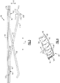
- an enlarged view of an example damper 86 is shown in Figure 3 .
- the damper 86 includes a first piece 88 having a first finger support 90 and a first plurality of fingers 92. As best seen in Figure 4 , the first fingers 92 are spaced-apart from one another relative to a circumferential direction X (i.e., about the engine central longitudinal axis A).
- the damper 86 also includes a second piece 94 having a second finger support 96 and a second plurality of fingers 98. As shown in Figure 4 , the damper 86 is arranged such that the first and second fingers 92, 98 are provided in an alternating arrangement. That is, moving in the circumferential direction X, one of the first fingers 92 is provided in the circumferential space between adjacent second fingers 98, and vice versa.
- the damper 86 further includes a third, bridge piece 100 connecting the first piece 88 and the second piece 94.
- the first finger support 90 is connected to a first axial end (e.g., the left-hand side of Figure 3 ) of the bridge piece 100
- the second finger support 96 is connected to the bridge piece 100 at an opposite, second axial end (e.g., the right-hand side of Figure 3 ).
- welds are provided at locations 102, 104 radially between the first finger support 90 and the bridge piece 100, and the second finger support 96 and the bridge piece 100, respectively.
- the bridge piece 100 is brazed to the first and second pieces 88, 94.
- the bridge piece 100 could be fastened to the first and second pieces 88, 94 using any known type of mechanical fastener.
- the fingers 92, 98 are shaped to provide a reliable engagement with the seal carrier 82.
- the shape of the fingers will now be described with reference to one of the first fingers 92.
- the finger 92 projects from the first finger support 90 toward an axially opposite side of the damper 86 (e.g., from left-to-right relative to Figure 3 ) at a non-zero angle 106 relative to the first finger support 90.
- the angle 106 is within a range of about 10 to 30 degrees.
- the first finger support 90 extends in a direction substantially parallel to the engine central longitudinal axis A.
- the finger 92 projects from the first finger support 90 and terminates at a free end 108.
- the free end 108 in this example is axially aligned (in the direction of the engine central longitudinal axis A) with the second finger support 94 and is radially spaced-apart (in the radial direction R) therefrom.
- the free end 108 has a curvature following a radius 110 having an origin 112 radially outward of the finger 92.
- the radius 110 is selected to provide the damper 86 with a relatively low profile. That is, the radius 110 provides the damper 86 with a relatively small height dimension (i.e., the dimension in the radial direction R) to allow the damper to fit into slots having small radial dimensions.
- the curvature of the free end 108 is such that the radially inner surface 114 of the finger 92 has an apex 116 that provides the radially innermost point of the finger 92.
- the terminal end 118 of the finger 92 is radially outward of the apex 116.
- the first piece 88 is made of a single, continuous piece of metallic material.
- the fingers 92 are shaped using a bending process.
- the second piece 94 is made of a single, continuous piece of metallic material, and the fingers 98 are shaped by a bending process.
- the third piece 100 is also made of a single, continuous piece of metallic material that is separate from the pieces providing the first and second pieces 88, 94.
- the first, second, and third pieces 88, 94, 100 are initially formed as separate structures and then connected together in this example. While the damper 86 includes multiple components, the damper 86 is relatively easy to manufacture because there is a minimal amount of bending required to make the fingers 92, 98.
- Figure 5 shows the detail of the arrangement of the damper 86 relative to the radially inner platform 78 and the seal carrier 82.
- the seal carrier 82 includes fore and aft engagement tabs 120, 122 received in respective fore and aft engagement slots 124, 126 formed in the radially inner platform 78.
- the damper 86 is provided axially between the fore and aft engagement tabs 120, 122, and is provided radially between a radially outer surface 128 of the seal carrier 82 and a radially inner surface 130 of the radially inner platform 78.
- the bridge piece 100 of the damper 86 is in direct contact with the radially inner surface 130 of the radially inner platform 78.
- the apexes (e.g., the apex 116) of the first fingers 92 and the second fingers 98 are in direct contact with the radially outer surface 128 of the seal carrier 82. As shown, the first fingers 92 contact the radially outer surface 128 at an aft location, and the second fingers 98 contact the radially outer surface at a fore location. The distance between the contact points provides a stable, reliable connection.
- the first and second fingers 92, 98 After being formed (e.g., being bent into position), the first and second fingers 92, 98 take on a "relaxed" position. Without any outside forces, the first and second fingers 92, 98 would remain in the relaxed position. When engaged with the radially outer surface 128 of the seal carrier 82, however, the fingers 92, 98 are urged radially outward relative to the relaxed position. The resiliency of the material of the fingers 92, 98 results in a biasing force being exerted by the damper 86 in a radially inward direction on the seal carrier 82.
- the damper 86 provides increased contact between the abradable annular seal 80 and the knife edges 84.
- the damper 86 thus allows for increased and more reliable sealing. Additionally, because of the axial spacing between the apexes of the fingers 92, 98, the force exerted on the seal carrier 82 is relatively uniform along the axial direction. This leads to a reduction in seal wear rate relative to dampers that provide a more centrally-located biasing force.
Description
- A gas turbine engine typically includes a fan section, a compressor section, a combustor section, and a turbine section. One way to increase the efficiency of the gas turbine engine is to decrease the amount of compressor air that leaks from the compressor section. In order to reduce unwanted air leaks from the compressor section, various seals are incorporated into the compressor section.
- One type of seal is a knife edge seal. Knife edge seals deter compressed air from leaking past the seal. In one known arrangement, knife edge seals project from a rotor disk toward an abradable material supported by a radially inner platform of a stator assembly. The stator assembly may include a damper configured to reduce vibrations between the knife edge seal, the abradable material, and the stator assembly.
-
EP 2613021 A2 discloses a damper spring provided between an array of stator vanes and an outer case, which supports the array. -
US 2012/0180500 A1 discloses a turbine combustor, including, a first wall disposed about a flow path of hot combustion gases, a second wall disposed about the first wall, and a damping system disposed between the first and second walls, wherein the damping system is configured to dampen vibration. -
EP 1441108 A2 discloses a damper for a stator assembly comprising a stator segment and a seal mounted to the stator segment locates between the stator segment and the seal. -
US 2014/0225334 A1 discloses a combustor seal structure which includes a first recess portion and a second recess portion that are provided on opposing faces in adjacent flange portions of a transition piece; a seal member body disposed across the first recess portion and the second recess portion; a first projection portion and a second projection portion that are provided at each end portion in the width direction of the seal member body and are capable of being in contact with a first seal face of the first recess portion and a second seal face of the second recess portion; a first spring member whose base end portion is connected to one end portion in the width direction of the seal member body and whose distal end portion extends to the other end portion and is capable of being in contact with a second pressing face. -
US 3,966,356 discloses a stationary annular rotor blade tip seal assembly which includes an annular support extending continuously circumferentially around and radially outwardly of the tips of a plurality of blades on a turbine rotor. - A stator assembly for a gas turbine engine according to an exemplary aspect of the present disclosure includes, among other things, at least one stator vane including a platform, a seal member connected to the platform, and a damper between the platform and the seal member. The damper includes a plurality of first fingers and a plurality of second fingers, which are provided circumferentially in an alternating arrangement.
- In a further non-limiting embodiment of the foregoing assembly, the damper includes a first piece supporting the first fingers, the damper includes a second piece supporting the second fingers, and the damper includes a bridge piece connected to both the first piece and the second piece.
- In a further non-limiting embodiment of the foregoing assembly, the bridge piece is in direct contact with the platform.
- In a further non-limiting embodiment of the foregoing assembly, the first piece includes a first finger support, the second piece includes a second finger support, the first fingers extend from the first finger support at a non-zero angle, and the second fingers extend from the second finger support at the non-zero angle.
- In a further non-limiting embodiment of the foregoing assembly, the non-zero angle is within a range of about 10 to 30 degrees.
- In a further non-limiting embodiment of the foregoing assembly, the first finger support and the second finger support extend in a direction substantially parallel to an engine central longitudinal axis.
- In a further non-limiting embodiment of the foregoing assembly, the first and second fingers include a free end having a curvature following a radius, and the radius has an origin radially outward of the respective finger.
- In a further non-limiting embodiment of the foregoing assembly, the free ends of the first and second fingers each have an apex providing a radially innermost point of the respective finger.
- In a further non-limiting embodiment of the foregoing assembly, the first and second fingers each have a terminal end spaced radially outward of the apex of the respective finger.
- In a further non-limiting embodiment of the foregoing assembly, the seal member supports an abradable seal material relative to a plurality of knife edge seals.
- In a further non-limiting embodiment of the foregoing assembly, the damper biases the seal carrier.
- A stator assembly for a gas turbine engine according to another exemplary aspect of the present disclosure includes, among other things, at least one stator vane including a platform, a seal member connected to the platform, and a damper between the platform and the seal member. The damper includes a plurality of first fingers and a plurality of second fingers. The damper further includes a first piece supporting the first fingers and a second piece supporting the second fingers. The first and second pieces are initially formed as separate structures.
- In a further non-limiting embodiment of the foregoing assembly, the damper includes a bridge piece connected to both the first piece and the second piece.
- In a further non-limiting embodiment of the foregoing assembly, the bridge piece is in direct contact with the platform, and wherein the plurality of first and second fingers are in direct contact with the seal member.
- A damper for a stator assembly according to an exemplary aspect of the present disclosure includes, among other things, a plurality of first fingers a plurality of second fingers. The first and second fingers are provided in an alternating arrangement.
- In a further non-limiting embodiment of the foregoing damper, the damper includes a first piece supporting the first fingers, a second piece supporting the second fingers, and a bridge piece connected to both the first piece and the second piece.
- In a further non-limiting embodiment of the foregoing damper, the first piece includes a first finger support, the second piece includes a second finger support, and the bridge piece is connected to the first finger support and the second finger support.
- In a further non-limiting embodiment of the foregoing damper, the first fingers extend from the first finger support at a non-zero angle, and the second fingers extend from the second finger support at the non-zero angle.
- In a further non-limiting embodiment of the foregoing damper, the non-zero angle is within a range of about 10 to 30 degrees.
- In a further non-limiting embodiment of the foregoing damper, the first finger support and the second finger support extend in a direction substantially parallel to one another.
- The embodiments, examples and alternatives of the preceding paragraphs, the claims, or the following description and drawings, including any of their various aspects or respective individual features, may be taken independently or in any combination. Features described in connection with one embodiment are applicable to all embodiments, unless such features are incompatible.
- The drawings can be briefly described as follows:
-
Figure 1 is a schematic view of an example gas turbine engine. -
Figure 2 is a schematic cross-section of a section for the gas turbine engine ofFigure 1 . -
Figure 3 is a side view of the damper ofFigure 2 . -
Figure 4 is an inner perspective view of the damper ofFigure 2 . -
Figure 5 is an enlarged view of a vane platform ofFigure 2 . -
Figure 1 schematically illustrates agas turbine engine 20. Thegas turbine engine 20 is disclosed herein as a two-spool turbofan that generally incorporates afan section 22, acompressor section 24, acombustor section 26 and aturbine section 28. Alternative engines might include an augmentor section (not shown) among other systems or features. Thefan section 22 drives air along a bypass flow path B in a bypass duct defined within anacelle 15, while thecompressor section 24 drives air along a core flow path C for compression and communication into thecombustor section 26 then expansion through theturbine section 28. Although depicted as a two-spool turbofan gas turbine engine in the disclosed non-limiting embodiment, it should be understood that the concepts described herein are not limited to use with two-spool turbofans as the teachings may be applied to other types of turbine engines including three-spool architectures. - The
exemplary engine 20 generally includes alow speed spool 30 and ahigh speed spool 32 mounted for rotation about an engine central longitudinal axis A relative to an enginestatic structure 36 viaseveral bearing systems 38. It should be understood thatvarious bearing systems 38 at various locations may alternatively or additionally be provided, and the location ofbearing systems 38 may be varied as appropriate to the application. - The
low speed spool 30 generally includes aninner shaft 40 that interconnects afan 42, a first (or low)pressure compressor 44 and a first (or low)pressure turbine 46. Theinner shaft 40 is connected to thefan 42 through a speed change mechanism, which in exemplarygas turbine engine 20 is illustrated as a gearedarchitecture 48 to drive thefan 42 at a lower speed than thelow speed spool 30. Thehigh speed spool 32 includes anouter shaft 50 that interconnects a second (or high)pressure compressor 52 and a second (or high)pressure turbine 54. Acombustor 56 is arranged inexemplary gas turbine 20 between thehigh pressure compressor 52 and thehigh pressure turbine 54. Amid-turbine frame 57 of the enginestatic structure 36 is arranged generally between thehigh pressure turbine 54 and thelow pressure turbine 46. Themid-turbine frame 57 further supports bearingsystems 38 in theturbine section 28. Theinner shaft 40 and theouter shaft 50 are concentric and rotate viabearing systems 38 about the engine central longitudinal axis A which is collinear with their longitudinal axes. - The core airflow is compressed by the
low pressure compressor 44 then thehigh pressure compressor 52, mixed and burned with fuel in thecombustor 56, then expanded over thehigh pressure turbine 54 andlow pressure turbine 46. Themid-turbine frame 57 includesairfoils 59 which are in the core airflow path C. Theturbines low speed spool 30 andhigh speed spool 32 in response to the expansion. It will be appreciated that each of the positions of thefan section 22,compressor section 24,combustor section 26,turbine section 28, and fandrive gear system 48 may be varied. For example,gear system 48 may be located aft ofcombustor section 26 or even aft ofturbine section 28, andfan section 22 may be positioned forward or aft of the location ofgear system 48. - The
engine 20 in one example is a high-bypass geared aircraft engine. In a further example, theengine 20 bypass ratio is greater than about six (6:1), with an example embodiment being greater than about ten (10:1), the gearedarchitecture 48 is an epicyclic gear train, such as a planetary gear system or other gear system, with a gear reduction ratio of greater than about 2.3:1 and thelow pressure turbine 46 has a pressure ratio that is greater than about five (5:1). In one disclosed embodiment, theengine 20 bypass ratio is greater than about ten (10:1), the fan diameter is significantly larger than that of thelow pressure compressor 44, and thelow pressure turbine 46 has a pressure ratio that is greater than about five (5:1).Low pressure turbine 46 pressure ratio is pressure measured prior to inlet oflow pressure turbine 46 as related to the pressure at the outlet of thelow pressure turbine 46 prior to an exhaust nozzle. The gearedarchitecture 48 may be an epicycle gear train, such as a planetary gear system or other gear system, with a gear reduction ratio of greater than about 2.3:1. It should be understood, however, that the above parameters are only exemplary of one embodiment of a geared architecture engine and that the present disclosure is applicable to other gas turbine engines including direct drive turbofans. -
Figure 2 is a schematic view of a section of thegas turbine engine 20. In this example, the section is thehigh pressure compressor 52. It should be understood, however, that other sections of thegas turbine engine 20 could benefit from this disclosure. Thehigh pressure compressor 52 includes multiple stages. For purposes of illustration, only afirst rotor assembly 60 and asecond rotor assembly 62 are shown. Thefirst rotor assembly 60 and thesecond rotor assembly 62 are attached to theouter shaft 50 ofFigure 1 . - The
first rotor assembly 60 includes a first array ofrotor blades 64 circumferentially spaced around afirst disk 66, and thesecond rotor assembly 62 includes a second array ofrotor blades 68 circumferentially spaced around asecond disk 70. An array ofstator vanes 72 is provided axially (relative to the engine central longitudinal axis A) between the first array ofrotor blades 64 and the second array ofrotor blades 68. - Each of the
stator vanes 72 has anairfoil section 74 radially extending (relative to the radial direction R, which is normal to the engine central longitudinal axis A) between a radiallyouter platform 76 and a radiallyinner platform 78. In this example, a seal member is supported relative to the radiallyinner platform 78. The seal member includes an abradableannular seal 80, such as honeycomb seal, and aseal carrier 82. Theseal carrier 82 supports the abradableannular seal 80 relative to knife edges 84 projecting radially outward from the first andsecond disks - A
damper 86 is provided between the radiallyinner platform 78 and theseal carrier 82. Thedamper 86 provides a continuous ring about the engine central longitudinal axis A or, alternatively, a plurality ofsegmented dampers 86 may circumferentially abut one another to form a segmented ring. For purposes of clarity, an enlarged view of anexample damper 86 is shown inFigure 3 . - With reference to
Figure 3 , thedamper 86 includes afirst piece 88 having afirst finger support 90 and a first plurality offingers 92. As best seen inFigure 4 , thefirst fingers 92 are spaced-apart from one another relative to a circumferential direction X (i.e., about the engine central longitudinal axis A). Thedamper 86 also includes asecond piece 94 having asecond finger support 96 and a second plurality offingers 98. As shown inFigure 4 , thedamper 86 is arranged such that the first andsecond fingers first fingers 92 is provided in the circumferential space between adjacentsecond fingers 98, and vice versa. - The
damper 86 further includes a third,bridge piece 100 connecting thefirst piece 88 and thesecond piece 94. As shown, thefirst finger support 90 is connected to a first axial end (e.g., the left-hand side ofFigure 3 ) of thebridge piece 100, and thesecond finger support 96 is connected to thebridge piece 100 at an opposite, second axial end (e.g., the right-hand side ofFigure 3 ). In one example, welds are provided atlocations first finger support 90 and thebridge piece 100, and thesecond finger support 96 and thebridge piece 100, respectively. In another example, thebridge piece 100 is brazed to the first andsecond pieces bridge piece 100 could be fastened to the first andsecond pieces - The
fingers seal carrier 82. The shape of the fingers will now be described with reference to one of thefirst fingers 92. As shown inFigure 3 , thefinger 92 projects from thefirst finger support 90 toward an axially opposite side of the damper 86 (e.g., from left-to-right relative toFigure 3 ) at anon-zero angle 106 relative to thefirst finger support 90. In one example, theangle 106 is within a range of about 10 to 30 degrees. Further, in this example, thefirst finger support 90 extends in a direction substantially parallel to the engine central longitudinal axis A. - With continued reference to
Figure 3 , thefinger 92 projects from thefirst finger support 90 and terminates at afree end 108. Thefree end 108 in this example is axially aligned (in the direction of the engine central longitudinal axis A) with thesecond finger support 94 and is radially spaced-apart (in the radial direction R) therefrom. Thefree end 108 has a curvature following aradius 110 having anorigin 112 radially outward of thefinger 92. - The
radius 110 is selected to provide thedamper 86 with a relatively low profile. That is, theradius 110 provides thedamper 86 with a relatively small height dimension (i.e., the dimension in the radial direction R) to allow the damper to fit into slots having small radial dimensions. The curvature of thefree end 108 is such that the radiallyinner surface 114 of thefinger 92 has an apex 116 that provides the radially innermost point of thefinger 92. Theterminal end 118 of thefinger 92 is radially outward of the apex 116. - In this example, the
first piece 88 is made of a single, continuous piece of metallic material. Thefingers 92 are shaped using a bending process. Likewise, thesecond piece 94 is made of a single, continuous piece of metallic material, and thefingers 98 are shaped by a bending process. Thethird piece 100 is also made of a single, continuous piece of metallic material that is separate from the pieces providing the first andsecond pieces third pieces damper 86 includes multiple components, thedamper 86 is relatively easy to manufacture because there is a minimal amount of bending required to make thefingers -
Figure 5 shows the detail of the arrangement of thedamper 86 relative to the radiallyinner platform 78 and theseal carrier 82. In this example, theseal carrier 82 includes fore andaft engagement tabs aft engagement slots inner platform 78. Thedamper 86 is provided axially between the fore andaft engagement tabs outer surface 128 of theseal carrier 82 and a radiallyinner surface 130 of the radiallyinner platform 78. - The
bridge piece 100 of thedamper 86 is in direct contact with the radiallyinner surface 130 of the radiallyinner platform 78. The apexes (e.g., the apex 116) of thefirst fingers 92 and thesecond fingers 98 are in direct contact with the radiallyouter surface 128 of theseal carrier 82. As shown, thefirst fingers 92 contact the radiallyouter surface 128 at an aft location, and thesecond fingers 98 contact the radially outer surface at a fore location. The distance between the contact points provides a stable, reliable connection. - After being formed (e.g., being bent into position), the first and
second fingers second fingers outer surface 128 of theseal carrier 82, however, thefingers fingers damper 86 in a radially inward direction on theseal carrier 82. - The
damper 86 provides increased contact between the abradableannular seal 80 and the knife edges 84. Thedamper 86 thus allows for increased and more reliable sealing. Additionally, because of the axial spacing between the apexes of thefingers seal carrier 82 is relatively uniform along the axial direction. This leads to a reduction in seal wear rate relative to dampers that provide a more centrally-located biasing force. - Again, it should be understood that terms such as "fore," "aft," "axial," "radial," and "circumferential" are used above with reference to the orientation of the objects in the figures, and with reference to the normal operational attitude of the
engine 20. Further, these terms have been used herein for purposes of explanation, and should not be considered otherwise limiting. Terms such as "generally," "substantially," and "about" are not intended to be boundaryless terms, and should be interpreted consistent with the way one skilled in the art would interpret the term. - Although the different examples have the specific components shown in the illustrations, embodiments of this disclosure are not limited to those particular combinations. It is possible to use some of the components or features from one of the examples in combination with features or components from another one of the examples.
- One of ordinary skill in this art would understand that the above-described embodiments are exemplary and non-limiting. That is, modifications of this disclosure would come within the scope of the claims. Accordingly, the following claims should be studied to determine their true scope and content.
Claims (15)
- A damper (86) for a stator assembly for a gas turbine engine comprising:a plurality of first fingers (92),characterized in that it further comprises a plurality of second fingers (98), the first and second fingers (92,98) provided circumferentially in an alternating arrangement.
- A stator assembly for a gas turbine engine (20), comprising:at least one stator vane (72) including a platform (78);a seal member connected to the platform (78); andthe damper (86) of claim 1, between the platform (78) and the seal member.
- The damper (86) or stator assembly as recited in claim 1 or 2, further comprising:a first piece (88) supporting the first fingers (92);a second piece (94) supporting the second fingers (98); anda bridge piece (100) connected to both the first piece (88) and the second piece (94).
- The stator assembly as recited in claim 3, wherein the bridge piece (100) is in direct contact with the platform (78).
- The damper (86) or stator assembly as recited in claim 3 or 4, wherein:the first piece (88) includes a first finger support (90); andthe second piece (94) includes a second finger support (96).
- The damper (86) or stator assembly as recited in claim 5, wherein the bridge piece (100) is connected to the first finger support (90) and the second finger support (96).
- The damper (86) or stator assembly as recited in claim 5 or 6, wherein:the first fingers (92) extend from the first finger support (90) at a non-zero angle; andthe second fingers (98) extend from the second finger support (96) at the non-zero angle.
- The damper (86) or stator assembly as recited in claim 7, wherein the non-zero angle is within a range of 10 to 30 degrees.
- The damper (86) or stator assembly as recited in any of claims 5 to 8, wherein the first finger support (90) and the second finger support (96) extend in a direction substantially parallel to one another, for example a direction substantially parallel to an engine central longitudinal axis.
- The damper (86) or stator assembly as recited in any preceding claim, wherein the first and second fingers (92,98) include a free end (108) having a curvature following a radius (110), the radius (110) having an origin (112) radially outward of the respective finger (92,98).
- The damper (86) or stator assembly as recited in claim 10, wherein the free ends (108) of the first and second fingers (92,98) each have an apex (116) providing a radially innermost point of the respective finger (92,98).
- The damper (86) or stator assembly as recited in claim 11, wherein the first and second fingers (92,98) each have a terminal end (118) spaced radially outward of the apex (116) of the respective finger (92,98).
- The stator assembly as recited in any of claims 2 to 12, wherein the seal member supports an abradable seal material (80) relative to a plurality of knife edge seals (84) and optionally the damper (86) biases a seal carrier (82).
- A stator assembly as recited in claim 2,
the damper (86) further including a first piece (88) supporting the first fingers (92) and a second piece (94) supporting the second fingers (98), wherein the first and second pieces (88,94) are initially formed as separate structures. - The assembly as recited in claim 14, wherein the damper (86) includes a bridge piece (100) connected to both the first piece (88) and the second piece (94), and optionally the bridge piece (100) is in direct contact with the platform (78), and the plurality of first and second fingers (92,98) are in direct contact with the seal member.
Applications Claiming Priority (1)
| Application Number | Priority Date | Filing Date | Title |
|---|---|---|---|
| US14/666,458 US9790809B2 (en) | 2015-03-24 | 2015-03-24 | Damper for stator assembly |
Publications (3)
| Publication Number | Publication Date |
|---|---|
| EP3073055A2 EP3073055A2 (en) | 2016-09-28 |
| EP3073055A3 EP3073055A3 (en) | 2016-11-02 |
| EP3073055B1 true EP3073055B1 (en) | 2018-08-22 |
Family
ID=55589777
Family Applications (1)
| Application Number | Title | Priority Date | Filing Date |
|---|---|---|---|
| EP16162070.3A Active EP3073055B1 (en) | 2015-03-24 | 2016-03-23 | Damper for stator assembly and stator assembly |
Country Status (2)
| Country | Link |
|---|---|
| US (1) | US9790809B2 (en) |
| EP (1) | EP3073055B1 (en) |
Families Citing this family (11)
| Publication number | Priority date | Publication date | Assignee | Title |
|---|---|---|---|---|
| EP3039316B1 (en) * | 2013-08-30 | 2020-10-21 | United Technologies Corporation | Sliding seal |
| WO2015031384A1 (en) * | 2013-08-30 | 2015-03-05 | United Technologies Corporation | Bifurcated sliding seal |
| US9845702B2 (en) * | 2015-04-27 | 2017-12-19 | United Technologies Corporation | Stator damper |
| BE1025283B1 (en) | 2017-06-02 | 2019-01-11 | Safran Aero Boosters S.A. | SEALING SYSTEM FOR TURBOMACHINE COMPRESSOR |
| US11473431B2 (en) * | 2019-03-12 | 2022-10-18 | Raytheon Technologies Corporation | Energy dissipating damper |
| FR3100838B1 (en) * | 2019-09-13 | 2021-10-01 | Safran Aircraft Engines | TURBOMACHINE SEALING RING |
| US11156110B1 (en) | 2020-08-04 | 2021-10-26 | General Electric Company | Rotor assembly for a turbine section of a gas turbine engine |
| KR102440257B1 (en) * | 2020-08-28 | 2022-09-05 | 두산에너빌리티 주식회사 | Sealing assembly and turbo-machine comprising the same |
| US11572794B2 (en) * | 2021-01-07 | 2023-02-07 | General Electric Company | Inner shroud damper for vibration reduction |
| US11655719B2 (en) | 2021-04-16 | 2023-05-23 | General Electric Company | Airfoil assembly |
| US11821320B2 (en) * | 2021-06-04 | 2023-11-21 | General Electric Company | Turbine engine with a rotor seal assembly |
Family Cites Families (27)
| Publication number | Priority date | Publication date | Assignee | Title |
|---|---|---|---|---|
| US3966356A (en) | 1975-09-22 | 1976-06-29 | General Motors Corporation | Blade tip seal mount |
| US4431373A (en) | 1980-05-16 | 1984-02-14 | United Technologies Corporation | Flow directing assembly for a gas turbine engine |
| US4897021A (en) | 1988-06-02 | 1990-01-30 | United Technologies Corporation | Stator vane asssembly for an axial flow rotary machine |
| US5346362A (en) * | 1993-04-26 | 1994-09-13 | United Technologies Corporation | Mechanical damper |
| US5785492A (en) | 1997-03-24 | 1998-07-28 | United Technologies Corporation | Method and apparatus for sealing a gas turbine stator vane assembly |
| US6042334A (en) | 1998-08-17 | 2000-03-28 | General Electric Company | Compressor interstage seal |
| US6547257B2 (en) * | 2001-05-04 | 2003-04-15 | General Electric Company | Combination transition piece floating cloth seal and stage 1 turbine nozzle flexible sealing element |
| US6808364B2 (en) | 2002-12-17 | 2004-10-26 | General Electric Company | Methods and apparatus for sealing gas turbine engine variable vane assemblies |
| US7291946B2 (en) | 2003-01-27 | 2007-11-06 | United Technologies Corporation | Damper for stator assembly |
| JP4577813B2 (en) * | 2003-08-20 | 2010-11-10 | イーグル・エンジニアリング・エアロスペース株式会社 | Sealing device |
| JP4322600B2 (en) * | 2003-09-02 | 2009-09-02 | イーグル・エンジニアリング・エアロスペース株式会社 | Sealing device |
| US7121800B2 (en) | 2004-09-13 | 2006-10-17 | United Technologies Corporation | Turbine blade nested seal damper assembly |
| CN101287898B (en) * | 2005-08-23 | 2010-06-16 | 三菱重工业株式会社 | Seal structure of gas turbine combustor |
| JP4918263B2 (en) | 2006-01-27 | 2012-04-18 | 三菱重工業株式会社 | Stator blade ring of axial compressor |
| US7635251B2 (en) | 2006-06-10 | 2009-12-22 | United Technologies Corporation | Stator assembly for a rotary machine |
| US7837435B2 (en) | 2007-05-04 | 2010-11-23 | Power System Mfg., Llc | Stator damper shim |
| US20090085305A1 (en) * | 2007-09-28 | 2009-04-02 | General Electric Company | High temperature seal |
| DE102007062681A1 (en) * | 2007-12-24 | 2009-06-25 | Man Turbo Ag | Sealing segment and sealing segment arrangement |
| WO2010073783A1 (en) | 2008-12-25 | 2010-07-01 | 三菱重工業株式会社 | Turbine blade and gas turbine |
| ES2382938T3 (en) | 2009-02-05 | 2012-06-14 | Siemens Aktiengesellschaft | An annular vane assembly for a gas turbine engine |
| US8511972B2 (en) * | 2009-12-16 | 2013-08-20 | Siemens Energy, Inc. | Seal member for use in a seal system between a transition duct exit section and a turbine inlet in a gas turbine engine |
| US20120180500A1 (en) | 2011-01-13 | 2012-07-19 | General Electric Company | System for damping vibration in a gas turbine engine |
| US8562000B2 (en) * | 2011-05-20 | 2013-10-22 | Siemens Energy, Inc. | Turbine combustion system transition piece side seals |
| US8951013B2 (en) | 2011-10-24 | 2015-02-10 | United Technologies Corporation | Turbine blade rail damper |
| US8899914B2 (en) | 2012-01-05 | 2014-12-02 | United Technologies Corporation | Stator vane integrated attachment liner and spring damper |
| US8920112B2 (en) * | 2012-01-05 | 2014-12-30 | United Technologies Corporation | Stator vane spring damper |
| JP6021675B2 (en) | 2013-02-13 | 2016-11-09 | 三菱重工業株式会社 | Combustor seal structure and seal for combustor |
-
2015
- 2015-03-24 US US14/666,458 patent/US9790809B2/en active Active
-
2016
- 2016-03-23 EP EP16162070.3A patent/EP3073055B1/en active Active
Non-Patent Citations (1)
| Title |
|---|
| None * |
Also Published As
| Publication number | Publication date |
|---|---|
| EP3073055A3 (en) | 2016-11-02 |
| US20160281531A1 (en) | 2016-09-29 |
| US9790809B2 (en) | 2017-10-17 |
| EP3073055A2 (en) | 2016-09-28 |
Similar Documents
| Publication | Publication Date | Title |
|---|---|---|
| EP3073055B1 (en) | Damper for stator assembly and stator assembly | |
| EP3064711B1 (en) | Component for a gas turbine engine, corresponding gas turbine engine and method of forming an airfoil | |
| EP3112606B1 (en) | A seal for a gas turbine engine | |
| EP3093445A1 (en) | Airfoil, corresponding vane and method of forming | |
| EP3450690B1 (en) | Turbine rotor | |
| EP3450691A1 (en) | Turbine rotor | |
| EP3101235B1 (en) | Seal assembly for a gas turbine engine | |
| WO2014168743A1 (en) | Integrally bladed rotor | |
| EP3190266B1 (en) | Gas turbine engine comprising a rotor hub seal | |
| US10746033B2 (en) | Gas turbine engine component | |
| EP2888449B1 (en) | Cantilevered airfoil, corresponding gas turbine engine and method of tuning | |
| US11230939B2 (en) | Vane seal system and seal therefor | |
| EP3095966B1 (en) | Support assembly for a gas turbine engine | |
| EP3623585B1 (en) | Pressure side cover for a variable camber vane assembly for a compressor of a gas turbine engine | |
| EP3623587B1 (en) | Airfoil assembly for a gas turbine engine | |
| EP3095971B1 (en) | Support assembly for a gas turbine engine | |
| EP3095967B1 (en) | Support assembly for a gas turbine engine | |
| US10119410B2 (en) | Vane seal system having spring positively locating seal member in axial direction | |
| US20160376903A1 (en) | Reversible blade rotor seal with protrusions | |
| EP3611347A1 (en) | Gas turbine engine with stator segments |
Legal Events
| Date | Code | Title | Description |
|---|---|---|---|
| PUAI | Public reference made under article 153(3) epc to a published international application that has entered the european phase |
Free format text: ORIGINAL CODE: 0009012 |
|
| AK | Designated contracting states |
Kind code of ref document: A2 Designated state(s): AL AT BE BG CH CY CZ DE DK EE ES FI FR GB GR HR HU IE IS IT LI LT LU LV MC MK MT NL NO PL PT RO RS SE SI SK SM TR |
|
| AX | Request for extension of the european patent |
Extension state: BA ME |
|
| PUAL | Search report despatched |
Free format text: ORIGINAL CODE: 0009013 |
|
| RAP1 | Party data changed (applicant data changed or rights of an application transferred) |
Owner name: UNITED TECHNOLOGIES CORPORATION |
|
| AK | Designated contracting states |
Kind code of ref document: A3 Designated state(s): AL AT BE BG CH CY CZ DE DK EE ES FI FR GB GR HR HU IE IS IT LI LT LU LV MC MK MT NL NO PL PT RO RS SE SI SK SM TR |
|
| AX | Request for extension of the european patent |
Extension state: BA ME |
|
| RIC1 | Information provided on ipc code assigned before grant |
Ipc: F01D 25/04 20060101ALI20160927BHEP Ipc: F01D 11/12 20060101ALI20160927BHEP Ipc: F01D 5/26 20060101ALI20160927BHEP Ipc: F01D 11/00 20060101ALI20160927BHEP Ipc: F01D 9/04 20060101AFI20160927BHEP |
|
| 17P | Request for examination filed |
Effective date: 20170502 |
|
| RBV | Designated contracting states (corrected) |
Designated state(s): AL AT BE BG CH CY CZ DE DK EE ES FI FR GB GR HR HU IE IS IT LI LT LU LV MC MK MT NL NO PL PT RO RS SE SI SK SM TR |
|
| STAA | Information on the status of an ep patent application or granted ep patent |
Free format text: STATUS: REQUEST FOR EXAMINATION WAS MADE |
|
| GRAP | Despatch of communication of intention to grant a patent |
Free format text: ORIGINAL CODE: EPIDOSNIGR1 |
|
| STAA | Information on the status of an ep patent application or granted ep patent |
Free format text: STATUS: GRANT OF PATENT IS INTENDED |
|
| INTG | Intention to grant announced |
Effective date: 20180227 |
|
| RIN1 | Information on inventor provided before grant (corrected) |
Inventor name: BUTCHER, RANDALL J. Inventor name: DUBE, DAVID P. Inventor name: LESLIE, NICHOLAS R. |
|
| GRAS | Grant fee paid |
Free format text: ORIGINAL CODE: EPIDOSNIGR3 |
|
| GRAA | (expected) grant |
Free format text: ORIGINAL CODE: 0009210 |
|
| STAA | Information on the status of an ep patent application or granted ep patent |
Free format text: STATUS: THE PATENT HAS BEEN GRANTED |
|
| AK | Designated contracting states |
Kind code of ref document: B1 Designated state(s): AL AT BE BG CH CY CZ DE DK EE ES FI FR GB GR HR HU IE IS IT LI LT LU LV MC MK MT NL NO PL PT RO RS SE SI SK SM TR |
|
| REG | Reference to a national code |
Ref country code: GB Ref legal event code: FG4D |
|
| REG | Reference to a national code |
Ref country code: CH Ref legal event code: EP |
|
| REG | Reference to a national code |
Ref country code: DE Ref legal event code: R096 Ref document number: 602016004888 Country of ref document: DE |
|
| REG | Reference to a national code |
Ref country code: AT Ref legal event code: REF Ref document number: 1032769 Country of ref document: AT Kind code of ref document: T Effective date: 20180915 |
|
| REG | Reference to a national code |
Ref country code: IE Ref legal event code: FG4D |
|
| REG | Reference to a national code |
Ref country code: NL Ref legal event code: MP Effective date: 20180822 |
|
| REG | Reference to a national code |
Ref country code: LT Ref legal event code: MG4D |
|
| PG25 | Lapsed in a contracting state [announced via postgrant information from national office to epo] |
Ref country code: BG Free format text: LAPSE BECAUSE OF FAILURE TO SUBMIT A TRANSLATION OF THE DESCRIPTION OR TO PAY THE FEE WITHIN THE PRESCRIBED TIME-LIMIT Effective date: 20181122 Ref country code: GR Free format text: LAPSE BECAUSE OF FAILURE TO SUBMIT A TRANSLATION OF THE DESCRIPTION OR TO PAY THE FEE WITHIN THE PRESCRIBED TIME-LIMIT Effective date: 20181123 Ref country code: IS Free format text: LAPSE BECAUSE OF FAILURE TO SUBMIT A TRANSLATION OF THE DESCRIPTION OR TO PAY THE FEE WITHIN THE PRESCRIBED TIME-LIMIT Effective date: 20181222 Ref country code: NO Free format text: LAPSE BECAUSE OF FAILURE TO SUBMIT A TRANSLATION OF THE DESCRIPTION OR TO PAY THE FEE WITHIN THE PRESCRIBED TIME-LIMIT Effective date: 20181122 Ref country code: RS Free format text: LAPSE BECAUSE OF FAILURE TO SUBMIT A TRANSLATION OF THE DESCRIPTION OR TO PAY THE FEE WITHIN THE PRESCRIBED TIME-LIMIT Effective date: 20180822 Ref country code: FI Free format text: LAPSE BECAUSE OF FAILURE TO SUBMIT A TRANSLATION OF THE DESCRIPTION OR TO PAY THE FEE WITHIN THE PRESCRIBED TIME-LIMIT Effective date: 20180822 Ref country code: LT Free format text: LAPSE BECAUSE OF FAILURE TO SUBMIT A TRANSLATION OF THE DESCRIPTION OR TO PAY THE FEE WITHIN THE PRESCRIBED TIME-LIMIT Effective date: 20180822 Ref country code: NL Free format text: LAPSE BECAUSE OF FAILURE TO SUBMIT A TRANSLATION OF THE DESCRIPTION OR TO PAY THE FEE WITHIN THE PRESCRIBED TIME-LIMIT Effective date: 20180822 Ref country code: SE Free format text: LAPSE BECAUSE OF FAILURE TO SUBMIT A TRANSLATION OF THE DESCRIPTION OR TO PAY THE FEE WITHIN THE PRESCRIBED TIME-LIMIT Effective date: 20180822 |
|
| REG | Reference to a national code |
Ref country code: AT Ref legal event code: MK05 Ref document number: 1032769 Country of ref document: AT Kind code of ref document: T Effective date: 20180822 |
|
| PG25 | Lapsed in a contracting state [announced via postgrant information from national office to epo] |
Ref country code: AL Free format text: LAPSE BECAUSE OF FAILURE TO SUBMIT A TRANSLATION OF THE DESCRIPTION OR TO PAY THE FEE WITHIN THE PRESCRIBED TIME-LIMIT Effective date: 20180822 Ref country code: LV Free format text: LAPSE BECAUSE OF FAILURE TO SUBMIT A TRANSLATION OF THE DESCRIPTION OR TO PAY THE FEE WITHIN THE PRESCRIBED TIME-LIMIT Effective date: 20180822 Ref country code: HR Free format text: LAPSE BECAUSE OF FAILURE TO SUBMIT A TRANSLATION OF THE DESCRIPTION OR TO PAY THE FEE WITHIN THE PRESCRIBED TIME-LIMIT Effective date: 20180822 |
|
| PG25 | Lapsed in a contracting state [announced via postgrant information from national office to epo] |
Ref country code: PL Free format text: LAPSE BECAUSE OF FAILURE TO SUBMIT A TRANSLATION OF THE DESCRIPTION OR TO PAY THE FEE WITHIN THE PRESCRIBED TIME-LIMIT Effective date: 20180822 Ref country code: CZ Free format text: LAPSE BECAUSE OF FAILURE TO SUBMIT A TRANSLATION OF THE DESCRIPTION OR TO PAY THE FEE WITHIN THE PRESCRIBED TIME-LIMIT Effective date: 20180822 Ref country code: ES Free format text: LAPSE BECAUSE OF FAILURE TO SUBMIT A TRANSLATION OF THE DESCRIPTION OR TO PAY THE FEE WITHIN THE PRESCRIBED TIME-LIMIT Effective date: 20180822 Ref country code: RO Free format text: LAPSE BECAUSE OF FAILURE TO SUBMIT A TRANSLATION OF THE DESCRIPTION OR TO PAY THE FEE WITHIN THE PRESCRIBED TIME-LIMIT Effective date: 20180822 Ref country code: IT Free format text: LAPSE BECAUSE OF FAILURE TO SUBMIT A TRANSLATION OF THE DESCRIPTION OR TO PAY THE FEE WITHIN THE PRESCRIBED TIME-LIMIT Effective date: 20180822 Ref country code: AT Free format text: LAPSE BECAUSE OF FAILURE TO SUBMIT A TRANSLATION OF THE DESCRIPTION OR TO PAY THE FEE WITHIN THE PRESCRIBED TIME-LIMIT Effective date: 20180822 Ref country code: EE Free format text: LAPSE BECAUSE OF FAILURE TO SUBMIT A TRANSLATION OF THE DESCRIPTION OR TO PAY THE FEE WITHIN THE PRESCRIBED TIME-LIMIT Effective date: 20180822 |
|
| REG | Reference to a national code |
Ref country code: DE Ref legal event code: R097 Ref document number: 602016004888 Country of ref document: DE |
|
| PG25 | Lapsed in a contracting state [announced via postgrant information from national office to epo] |
Ref country code: SK Free format text: LAPSE BECAUSE OF FAILURE TO SUBMIT A TRANSLATION OF THE DESCRIPTION OR TO PAY THE FEE WITHIN THE PRESCRIBED TIME-LIMIT Effective date: 20180822 Ref country code: DK Free format text: LAPSE BECAUSE OF FAILURE TO SUBMIT A TRANSLATION OF THE DESCRIPTION OR TO PAY THE FEE WITHIN THE PRESCRIBED TIME-LIMIT Effective date: 20180822 Ref country code: SM Free format text: LAPSE BECAUSE OF FAILURE TO SUBMIT A TRANSLATION OF THE DESCRIPTION OR TO PAY THE FEE WITHIN THE PRESCRIBED TIME-LIMIT Effective date: 20180822 |
|
| PLBE | No opposition filed within time limit |
Free format text: ORIGINAL CODE: 0009261 |
|
| STAA | Information on the status of an ep patent application or granted ep patent |
Free format text: STATUS: NO OPPOSITION FILED WITHIN TIME LIMIT |
|
| 26N | No opposition filed |
Effective date: 20190523 |
|
| PG25 | Lapsed in a contracting state [announced via postgrant information from national office to epo] |
Ref country code: SI Free format text: LAPSE BECAUSE OF FAILURE TO SUBMIT A TRANSLATION OF THE DESCRIPTION OR TO PAY THE FEE WITHIN THE PRESCRIBED TIME-LIMIT Effective date: 20180822 |
|
| PG25 | Lapsed in a contracting state [announced via postgrant information from national office to epo] |
Ref country code: MC Free format text: LAPSE BECAUSE OF FAILURE TO SUBMIT A TRANSLATION OF THE DESCRIPTION OR TO PAY THE FEE WITHIN THE PRESCRIBED TIME-LIMIT Effective date: 20180822 |
|
| REG | Reference to a national code |
Ref country code: CH Ref legal event code: PL |
|
| PG25 | Lapsed in a contracting state [announced via postgrant information from national office to epo] |
Ref country code: LU Free format text: LAPSE BECAUSE OF NON-PAYMENT OF DUE FEES Effective date: 20190323 |
|
| REG | Reference to a national code |
Ref country code: BE Ref legal event code: MM Effective date: 20190331 |
|
| PG25 | Lapsed in a contracting state [announced via postgrant information from national office to epo] |
Ref country code: CH Free format text: LAPSE BECAUSE OF NON-PAYMENT OF DUE FEES Effective date: 20190331 Ref country code: IE Free format text: LAPSE BECAUSE OF NON-PAYMENT OF DUE FEES Effective date: 20190323 Ref country code: LI Free format text: LAPSE BECAUSE OF NON-PAYMENT OF DUE FEES Effective date: 20190331 |
|
| PG25 | Lapsed in a contracting state [announced via postgrant information from national office to epo] |
Ref country code: BE Free format text: LAPSE BECAUSE OF NON-PAYMENT OF DUE FEES Effective date: 20190331 |
|
| PG25 | Lapsed in a contracting state [announced via postgrant information from national office to epo] |
Ref country code: TR Free format text: LAPSE BECAUSE OF FAILURE TO SUBMIT A TRANSLATION OF THE DESCRIPTION OR TO PAY THE FEE WITHIN THE PRESCRIBED TIME-LIMIT Effective date: 20180822 |
|
| PG25 | Lapsed in a contracting state [announced via postgrant information from national office to epo] |
Ref country code: PT Free format text: LAPSE BECAUSE OF FAILURE TO SUBMIT A TRANSLATION OF THE DESCRIPTION OR TO PAY THE FEE WITHIN THE PRESCRIBED TIME-LIMIT Effective date: 20181222 Ref country code: MT Free format text: LAPSE BECAUSE OF NON-PAYMENT OF DUE FEES Effective date: 20190323 |
|
| PG25 | Lapsed in a contracting state [announced via postgrant information from national office to epo] |
Ref country code: CY Free format text: LAPSE BECAUSE OF FAILURE TO SUBMIT A TRANSLATION OF THE DESCRIPTION OR TO PAY THE FEE WITHIN THE PRESCRIBED TIME-LIMIT Effective date: 20180822 |
|
| PG25 | Lapsed in a contracting state [announced via postgrant information from national office to epo] |
Ref country code: HU Free format text: LAPSE BECAUSE OF FAILURE TO SUBMIT A TRANSLATION OF THE DESCRIPTION OR TO PAY THE FEE WITHIN THE PRESCRIBED TIME-LIMIT; INVALID AB INITIO Effective date: 20160323 |
|
| PG25 | Lapsed in a contracting state [announced via postgrant information from national office to epo] |
Ref country code: MK Free format text: LAPSE BECAUSE OF FAILURE TO SUBMIT A TRANSLATION OF THE DESCRIPTION OR TO PAY THE FEE WITHIN THE PRESCRIBED TIME-LIMIT Effective date: 20180822 |
|
| REG | Reference to a national code |
Ref country code: DE Ref legal event code: R081 Ref document number: 602016004888 Country of ref document: DE Owner name: RAYTHEON TECHNOLOGIES CORPORATION (N.D.GES.D.S, US Free format text: FORMER OWNER: UNITED TECHNOLOGIES CORPORATION, FARMINGTON, CONN., US |
|
| PGFP | Annual fee paid to national office [announced via postgrant information from national office to epo] |
Ref country code: FR Payment date: 20230222 Year of fee payment: 8 |
|
| PGFP | Annual fee paid to national office [announced via postgrant information from national office to epo] |
Ref country code: GB Payment date: 20230222 Year of fee payment: 8 Ref country code: DE Payment date: 20230221 Year of fee payment: 8 |
|
| P01 | Opt-out of the competence of the unified patent court (upc) registered |
Effective date: 20230520 |
|
| PGFP | Annual fee paid to national office [announced via postgrant information from national office to epo] |
Ref country code: DE Payment date: 20240220 Year of fee payment: 9 Ref country code: GB Payment date: 20240220 Year of fee payment: 9 |