EP2620596A2 - Turbine exhaust diffuser system - Google Patents
Turbine exhaust diffuser system Download PDFInfo
- Publication number
- EP2620596A2 EP2620596A2 EP13152397.9A EP13152397A EP2620596A2 EP 2620596 A2 EP2620596 A2 EP 2620596A2 EP 13152397 A EP13152397 A EP 13152397A EP 2620596 A2 EP2620596 A2 EP 2620596A2
- Authority
- EP
- European Patent Office
- Prior art keywords
- exhaust diffuser
- diffuser system
- wall
- turbine exhaust
- manways
- Prior art date
- Legal status (The legal status is an assumption and is not a legal conclusion. Google has not performed a legal analysis and makes no representation as to the accuracy of the status listed.)
- Withdrawn
Links
Images
Classifications
-
- F—MECHANICAL ENGINEERING; LIGHTING; HEATING; WEAPONS; BLASTING
- F01—MACHINES OR ENGINES IN GENERAL; ENGINE PLANTS IN GENERAL; STEAM ENGINES
- F01D—NON-POSITIVE DISPLACEMENT MACHINES OR ENGINES, e.g. STEAM TURBINES
- F01D25/00—Component parts, details, or accessories, not provided for in, or of interest apart from, other groups
- F01D25/30—Exhaust heads, chambers, or the like
-
- F—MECHANICAL ENGINEERING; LIGHTING; HEATING; WEAPONS; BLASTING
- F01—MACHINES OR ENGINES IN GENERAL; ENGINE PLANTS IN GENERAL; STEAM ENGINES
- F01D—NON-POSITIVE DISPLACEMENT MACHINES OR ENGINES, e.g. STEAM TURBINES
- F01D9/00—Stators
- F01D9/06—Fluid supply conduits to nozzles or the like
- F01D9/065—Fluid supply or removal conduits traversing the working fluid flow, e.g. for lubrication-, cooling-, or sealing fluids
Definitions
- the subject matter disclosed herein relates to turbine exhaust diffuser systems and, more particularly, to manways in turbine exhaust diffuser systems.
- a turbine system may include an exhaust diffuser system coupled to a turbine section downstream of the turbine section.
- a turbine system may be either a gas turbine system or a steam turbine system.
- a gas turbine system combusts a mixture of fuel and air to generate hot combustion gases, which in turn drive one or more turbines.
- the hot combustion gases force turbine blades to rotate, thereby driving a shaft to cause rotation of one or more loads, e.g., electrical generators, and so forth.
- the exhaust diffuser system receives the exhaust from the turbine. As the exhaust flows through diverging passages of the exhaust diffuser system, dynamic pressure of the exhaust flow may cause the static pressure in the exhaust diffuser system to increase.
- Exhaust diffuser systems may contain manways that extend through the exhaust diffuser system radially from an outer wall to an inner hub, or wall, that surrounds an access tunnel.
- the manways may contain pipes that provide lubrication oil and/or cooling air to the turbine system.
- the pipes extend into the access tunnel of the exhaust diffuser system and may limit entry and/or use of the access tunnel, such as by blocking entry through an access door.
- the arrangement of the manways may cause exhaust to flow around the manways and generate wakes. Undesirable vortex shedding may result from the wakes and may affect the structure of the exhaust diffuser system. Further, the vortex shedding may increase pressure loss of the exhaust diffuser system, increase noise of the exhaust diffuser system, and decrease the overall performance of the exhaust diffuser system.
- a turbine exhaust diffuser system in a first aspect, includes an outer wall.
- the turbine exhaust diffuser system also includes an inner wall formed by a converging inner passageway.
- Turbine exhaust is configured to flow through an area between the outer wall and the inner wall.
- the turbine exhaust diffuser system includes at least one manway extending from the outer wall to the inner wall. The at least one manway extends from the outer wall to the inner wall at an angle that is not perpendicular to a central axis of the turbine exhaust diffuser system.
- a turbine exhaust diffuser system in a second aspect, includes an outer wall of a turbine exhaust passageway.
- the turbine exhaust diffuser system also includes an access passageway defined by an inner wall of the turbine exhaust passageway.
- the access passageway is configured to enable an operator to enter the access passageway to perform maintenance on the turbine exhaust diffuser system.
- the turbine exhaust diffuser system includes a plurality of manways extending from the outer wall of the turbine exhaust passageway to the access passageway. Each manway extends from the outer wall of the turbine exhaust passageway to the access passageway at an angle that is not perpendicular to a central axis of the turbine exhaust diffuser system.
- a turbine exhaust diffuser system in a third aspect, includes a plurality of manways extending between an outer wall and an interior access tunnel at an angle that is not perpendicular to a central axis of the turbine exhaust diffuser system.
- certain embodiments of a turbine exhaust diffuser system include manways that extend through the exhaust diffuser system at an angle that is not perpendicular to a central axis of the exhaust diffuser system.
- the manways may extend through the exhaust diffuser system at an angle that is shifted within the range of approximately 5 to 25 degrees, 3 to 15 degrees, or 10 to 30 degrees from being perpendicular to the central axis of the diffuser system (e.g., the angle between the manways and the central axis may be within a range of approximately 95 and 115 degrees, 93 to 105 degrees, or 100 to 120 degrees).
- the manways may extend through the exhaust diffuser system at an angle that is shifted approximately 15 degrees from being perpendicular to the central axis of the diffuser system. Consequently, due to the manways not being perpendicular to the central axis of the exhaust diffuser system, the amount of space for operator entry into an access tunnel of the exhaust diffuser system is increased. Further, the amplitude and frequency of vortex shedding (i.e., the unsteady flow of exhaust around the manways) is decreased when compared to systems that have manways perpendicular to the central axis of the exhaust diffuser system. As such, the exhaust diffuser systems described herein not only facilitate maintenance of the exhaust diffuser systems by human operators, but also enhance operational characteristics of the exhaust diffuser systems.
- the gas turbine engine 100 extends in an axial direction 102.
- a radial direction 104 illustrates a direction extending outward from a central axis 105 of the gas turbine engine 100.
- a circumferential direction 106 illustrates the rotational direction around the central axis 105 of the gas turbine engine 100.
- the gas turbine engine 100 includes one or more fuel nozzles 108 located inside a combustor section 110.
- the gas turbine engine 100 may include multiple combustors 120 disposed in an annular (e.g., circumferential 106) arrangement within the combustor section 110.
- each combustor 120 may include multiple fuel nozzles 108 attached to or near a head end of each combustor 120 in an annular (e.g., circumferential 106) or other arrangement.
- the compressed air from the compressor 124 is then directed into the combustor section 110, where the compressed air is mixed with fuel.
- the mixture of compressed air and fuel is generally burned within the combustor section 110 to generate high-temperature, high-pressure combustion gases, which are used to generate torque within a turbine section 130 of the gas turbine engine 100.
- multiple combustors 120 may be annularly (e.g., circumferentially 106) disposed within the combustor section 110 of the gas turbine engine 100.
- Each combustor 120 includes a transition piece 172 that directs the hot combustion gases from the combustor 120 to the turbine section 130 of the gas turbine engine 100.
- each transition piece 172 generally defines a hot gas path from the combustor 120 to a nozzle assembly of the turbine section 130, included within a first stage 174 of the turbine section 130 of the gas turbine engine 100.
- the turbine section 130 includes three separate stages or sections 174 (i.e., first stage or section), 176 (i.e., second stage or section), and 178 (i.e., third stage or section, or last turbine bucket section). Although illustrated as including three stages 174, 176, 178, it will be understood that, in other embodiments, the turbine section 130 may include any number of stages.
- Each stage 174, 176, and 178 includes blades 180 coupled to a rotor wheel 182 rotatably attached to a shaft 184.
- each of the turbine blades 180 may be considered a turbine bucket, or a bucket.
- Each stage 174, 176, and 178 also includes a nozzle assembly 186 disposed directly upstream of each set of blades 180.
- the nozzle assemblies 186 direct the hot combustion gases toward the blades 180 where the hot combustion gases apply motive forces to the blades 180 to rotate the blades 180, thereby turning the shaft 184. As a result, the blades 180 and shaft 184 rotate in the circumferential direction 106.
- the hot combustion gases flow through each of the stages 174, 176, and 178 applying motive forces to the blades 180 within each stage 174, 176, and 178.
- the hot combustion gases may then exit the gas turbine section 130 into an exhaust diffuser system 188 of the gas turbine engine 100.
- the exhaust diffuser system 188 reduces the velocity of fluid flow of the exhaust combustion gases from the gas turbine section 130, and also increases the static pressure of the exhaust combustion gases to increase the work produced by the gas turbine engine 100.
- the last turbine bucket section 178 of the turbine section 130 includes a clearance 194 between ends of a plurality of last turbine bucket blades 195 (e.g., the last blade 180 of the gas turbine section 130) and a stationary shroud 196 disposed about the plurality of last turbine bucket blades 195.
- an outer wall 198 of the exhaust diffuser system 188 extends from the stationary shroud 196.
- a strut 200 is illustrated abutting the outer wall 198. Struts 200 are used to support the structure of the exhaust diffuser section 188.
- a manway 202 extends between the outer wall 198 and an inner wall 204 of the exhaust diffuser system 188.
- the manway 202 may encompass pipes or tubes that are used to transport fluids from outside the exhaust diffuser system 188 for use within the exhaust diffuser system 188.
- the inner wall 204 is formed by the outside of an access tunnel or converging passageway 206.
- the inner wall 204 may extend at an angle 205 that is not parallel to the central axis 105.
- the angle 205 between the inner wall 204 and the central axis 105 may be approximately 5 to 10 degrees, 3 to 7 degrees, or 8 to 15 degrees.
- the manway 202 extends through the exhaust diffuser system 188 at an angle that is not perpendicular to the central axis 105.
- exhaust e.g., the exhaust combustion gases from the gas turbine section 130
- the exhaust flow is directed around the manway 202 to exit the exhaust diffuser system 188.
- the manway 202 may cause vortex shedding to occur.
- the amplitude and frequency of the vortex shedding may be lower in the present embodiments than in systems with manways 202 that are perpendicular to the central axis 105.
- FIG. 2 is a perspective view of an embodiment of the gas turbine exhaust diffuser system 188.
- the struts 200 are disposed around the inner wall 204 of the exhaust diffuser system 188 and extend radially 104 from the inner wall 204 to the outer wall 198 of the exhaust diffuser system 188 and thereby structurally support the outer wall 198 of the exhaust diffuser system 188.
- turbine exhaust flows into the exhaust diffuser system 188
- the exhaust flows through an area between the inner wall 204 and the outer wall 198.
- the exhaust flows around the struts 200, which alters the exhaust flow. Therefore, the properties of how the exhaust flows through the exhaust diffuser system 188 are affected by the shape and position of the struts 200.
- FIG. 3 is a side view of an embodiment of the gas turbine exhaust diffuser system 188.
- FIG. 3 illustrates how multiple struts 200 may be arranged around the inner wall 204 of the exhaust diffuser system 188.
- the manways 202 are located behind the struts 200 (within the exhaust diffuser system 188).
- the manways 202 also extend between the inner wall 204 and the outer wall 198 and may provide further support between the inner wall 204 and the outer wall 198.
- three manways 202 are illustrated, however, other embodiments of the exhaust diffuser system 188 may have fewer or more manways 202.
- FIG. 4 is a cross-sectional side view of an embodiment of the gas turbine exhaust diffuser system 188.
- two manways 202 are depicted, a first manway 236 and a second manway 238.
- the manways 202 extend from the outer wall 198 to the inner wall 204 and extend through an exhaust flow area 240 through which the turbine exhaust from the turbine section 130 flows.
- the manways 202 are illustrated as having a generally race-track shaped wall, the manways 202 walls may have any suitable shape (e.g., cylindrical, airfoil, etc.). Further, the shape of the manways 202 may be designed to achieve optimal flow of exhaust around the manways 202.
- pipes 241 and 242 may be disposed within the manways 202 and extend from the manways 202 into the access tunnel 206 defined within the inner wall 204 of the exhaust diffuser system 188.
- the pipes 241 and 242 may be used for transporting fluid to be used by the turbine exhaust diffuser system 188.
- the pipe 241 may be used to transport lubricating fluid (e.g., oil) through the manway 236 to the access tunnel 206 to be used by the exhaust diffuser system 188 (e.g., to lubricate bearings).
- the pipe 242 may be used to transport cooling air or fluid through the manway 238 to the access tunnel 206 to be used for reducing the temperature of components within the exhaust diffuser system 188.
- the pipes 241 and 242 extend through the access tunnel 206 from an entry location 243 (e.g., where the manways 202 intersect with the access tunnel 206) toward a strut region 244 of the access tunnel 206.
- the access tunnel 206 forms a cone like shape which generally increases in diameter as the access tunnel 206 extends from the entry location 243 toward the strut region 244. Therefore, a distance 246 between the pipes 241 and 242 may be based on the entry location 243 of the pipes 241 and 242 into the access tunnel 206. As may be appreciated, the distance 246 between the pipes 241 and 242 may affect heat transfer that occurs between the pipes 241 and 242.
- the distance 246 as well as the distances between the pipes 241 and 242 and the inner wall 204 may affect the ability of an operator to move through the access tunnel 206, such as to perform maintenance.
- the manways 202 extend at an angle from the outer wall 198 toward the inner wall 204 that is not perpendicular to the central axis 105.
- the location of the manways 202 may cause the pipes 241 and 242 to enter the access tunnel 206 at a location where the access tunnel 206 has a larger diameter than if the manways 202 extended toward the access tunnel 206 at an angle perpendicular to the central axis 105, assuming that the manways 202 extend from the same location of the outer wall 198 in both instances.
- the distance 246 may increase and allow more space for an operator to move within the access tunnel 206. For example, the distance 246 may increase because the pipes 241 and 242 may extend from an entry location 243 where the access tunnel 206 has a larger diameter than in other entry locations.
- the larger diameter enables the pipes 241 and 242 to remain a greater distance 246 from each other as they extend into the access tunnel 206, remain close to the inner wall 204, and extend toward the strut region 244.
- heat transfer between the pipes 241 and 242 may decrease as the distance 246 increases.
- An entry distance 248 is the distance between the pipes 241 and 242 and an access door 249 (at a downstream end of the access tunnel 206), which is used by an operator to enter the access tunnel 206. As may be appreciated, as the entry distance 248 increases, there is greater space for the operator to enter the access tunnel 206 through the access door 249.
- the entry distance 248 is greater in the present embodiments than in systems where the manways 202 extend perpendicular to the central axis 105, again assuming that the manways 202 extend from the same location of the outer wall 198 in both instances.
- each manway 202 There are generally two sides of each manway 202. Specifically, an upstream end 250 (e.g., the side of the manway 202 closest to the struts 200) and a downstream end 252 (e.g., the side of the manway 202 farthest from the struts 200). As illustrated, the angle between the manways 202 and the central axis 105 may be described using an upstream angle 254 (e.g., the angle between the upstream end 250 and the central axis 105) or a downstream angle 256 (e.g., the angle between the downstream end 252 of the manway 202 and the central axis 105).
- an upstream angle 254 e.g., the angle between the upstream end 250 and the central axis 105
- a downstream angle 256 e.g., the angle between the downstream end 252 of the manway 202 and the central axis 105.
- the upstream angle 254 may be any suitable angle greater than 90 degrees (e.g., not perpendicular), and the downstream angle 256 may be any suitable angle less than 90 degrees (e.g., not perpendicular).
- the upstream angle 254 may be within a range of approximately 95 to 115 degrees, 93 to 105 degrees, or 100 to 120 degrees.
- the upstream angle 254 may be approximately 105 degrees.
- the downstream angle 256 may be within a range of approximately 65 to 85 degrees, 75 to 87 degrees, or 60 to 80 degrees.
- the downstream angle 256 may be approximately 85 degrees.
- the upstream angle 254 and the downstream angle 256 are supplementary angles (i.e., they combine to equal 180 degrees).
- exhaust flows through the exhaust diffuser system 188.
- the exhaust enters the exhaust diffuser system 188, flows around the struts 200, then flows through the exhaust flow area 240 and around the manways 202 before the exhaust exits the exhaust diffuser system 188.
- the manways 202 may cause vortex shedding to occur.
- the amplitude and frequency of the vortex shedding may be lower than in systems with manways 202 that are perpendicular to the central axis 105. More specifically, because the manways 202 are angled away from the impinging flow of the exhaust, the amplitude and frequency of vortex shedding may be drastically reduced as compared to perpendicular manways 202.
- the technical effects of the present invention include providing greater access for an operator to enter and maneuver within the access tunnel 206. Further, heat transfer between pipes within the access tunnel 206 is decreased as the pipes are moved away from each other within the access tunnel 206. In addition, the amplitude and frequency of the vortex shedding is decreased (e.g., the flow of exhaust through the exhaust diffuser system 188 is disturbed less). As a result, there may be a decrease in pressure loss, a decrease in noise, and an increase in overall diffuser performance in the present embodiments when compared to systems with manways 202 that are perpendicular to the central axis 105.
Abstract
A turbine exhaust diffuser system (188) includes a plurality of manways (202). The plurality of manways (202) each extend between an outer wall (198) of the turbine exhaust diffuser system (188) and an interior access tunnel (206) of the turbine exhaust diffuser system (188). The plurality of manways (202) extend between the outer wall (198) and the access tunnel (206) at an angle that is not perpendicular to a central axis (105) of the turbine exhaust diffuser system (188).
Description
- The subject matter disclosed herein relates to turbine exhaust diffuser systems and, more particularly, to manways in turbine exhaust diffuser systems.
- A turbine system may include an exhaust diffuser system coupled to a turbine section downstream of the turbine section. Such a turbine system may be either a gas turbine system or a steam turbine system. For example, a gas turbine system combusts a mixture of fuel and air to generate hot combustion gases, which in turn drive one or more turbines. In particular, the hot combustion gases force turbine blades to rotate, thereby driving a shaft to cause rotation of one or more loads, e.g., electrical generators, and so forth. The exhaust diffuser system receives the exhaust from the turbine. As the exhaust flows through diverging passages of the exhaust diffuser system, dynamic pressure of the exhaust flow may cause the static pressure in the exhaust diffuser system to increase.
- Exhaust diffuser systems may contain manways that extend through the exhaust diffuser system radially from an outer wall to an inner hub, or wall, that surrounds an access tunnel. The manways may contain pipes that provide lubrication oil and/or cooling air to the turbine system. The pipes extend into the access tunnel of the exhaust diffuser system and may limit entry and/or use of the access tunnel, such as by blocking entry through an access door. Further, the arrangement of the manways may cause exhaust to flow around the manways and generate wakes. Undesirable vortex shedding may result from the wakes and may affect the structure of the exhaust diffuser system. Further, the vortex shedding may increase pressure loss of the exhaust diffuser system, increase noise of the exhaust diffuser system, and decrease the overall performance of the exhaust diffuser system.
- Certain embodiments commensurate in scope with the originally claimed invention are summarized below. These embodiments are not intended to limit the scope of the claimed invention, but rather these embodiments are intended only to provide a brief summary of possible forms of the invention. Indeed, the invention may encompass a variety of forms that may be similar to or different from the embodiments set forth below.
- In a first aspect, the invention resides in a turbine exhaust diffuser system includes an outer wall. The turbine exhaust diffuser system also includes an inner wall formed by a converging inner passageway. Turbine exhaust is configured to flow through an area between the outer wall and the inner wall. The turbine exhaust diffuser system includes at least one manway extending from the outer wall to the inner wall. The at least one manway extends from the outer wall to the inner wall at an angle that is not perpendicular to a central axis of the turbine exhaust diffuser system.
- In a second aspect, a turbine exhaust diffuser system includes an outer wall of a turbine exhaust passageway. The turbine exhaust diffuser system also includes an access passageway defined by an inner wall of the turbine exhaust passageway. The access passageway is configured to enable an operator to enter the access passageway to perform maintenance on the turbine exhaust diffuser system. The turbine exhaust diffuser system includes a plurality of manways extending from the outer wall of the turbine exhaust passageway to the access passageway. Each manway extends from the outer wall of the turbine exhaust passageway to the access passageway at an angle that is not perpendicular to a central axis of the turbine exhaust diffuser system.
- In a third aspect, a turbine exhaust diffuser system includes a plurality of manways extending between an outer wall and an interior access tunnel at an angle that is not perpendicular to a central axis of the turbine exhaust diffuser system.
- Embodiments of the present invention will now be described, by way of example only, with reference to the accompanying drawings in which:
-
FIG. 1 is a cross-sectional side view of an embodiment of a gas turbine engine; -
FIG. 2 is a perspective view of an embodiment of a gas turbine exhaust diffuser system that may be used with the gas turbine engine ofFIG. 1 ; -
FIG. 3 is a side view of an embodiment of the gas turbine exhaust diffuser system ofFIG. 2 ; and -
FIG. 4 is a cross-sectional side view of an embodiment of a gas turbine exhaust diffuser system that may be used with the gas turbine engine ofFIG. 1 . - One or more specific embodiments of the present invention will be described below. In an effort to provide a concise description of these embodiments, all features of an actual implementation may not be described in the specification. It should be appreciated that in the development of any such actual implementation, as in any engineering or design project, numerous implementation-specific decisions must be made to achieve the developers' specific goals, such as compliance with system-related and business-related constraints, which may vary from one implementation to another. Moreover, it should be appreciated that such a development effort might be complex and time consuming, but would nevertheless be a routine undertaking of design, fabrication, and manufacture for those of ordinary skill having the benefit of this disclosure.
- When introducing elements of various embodiments of the present invention, the articles "a," "an," "the," and "said" are intended to mean that there are one or more of the elements. The terms "comprising," "including," and "having" are intended to be inclusive and mean that there may be additional elements other than the listed elements.
- As discussed below, certain embodiments of a turbine exhaust diffuser system include manways that extend through the exhaust diffuser system at an angle that is not perpendicular to a central axis of the exhaust diffuser system. For example, the manways may extend through the exhaust diffuser system at an angle that is shifted within the range of approximately 5 to 25 degrees, 3 to 15 degrees, or 10 to 30 degrees from being perpendicular to the central axis of the diffuser system (e.g., the angle between the manways and the central axis may be within a range of approximately 95 and 115 degrees, 93 to 105 degrees, or 100 to 120 degrees). Specifically, in certain embodiments, the manways may extend through the exhaust diffuser system at an angle that is shifted approximately 15 degrees from being perpendicular to the central axis of the diffuser system. Consequently, due to the manways not being perpendicular to the central axis of the exhaust diffuser system, the amount of space for operator entry into an access tunnel of the exhaust diffuser system is increased. Further, the amplitude and frequency of vortex shedding (i.e., the unsteady flow of exhaust around the manways) is decreased when compared to systems that have manways perpendicular to the central axis of the exhaust diffuser system. As such, the exhaust diffuser systems described herein not only facilitate maintenance of the exhaust diffuser systems by human operators, but also enhance operational characteristics of the exhaust diffuser systems.
- Turning now to the drawings and referring first to
FIG. 1 , an embodiment of agas turbine engine 100 is illustrated. Thegas turbine engine 100 extends in anaxial direction 102. Aradial direction 104 illustrates a direction extending outward from acentral axis 105 of thegas turbine engine 100. Further, acircumferential direction 106 illustrates the rotational direction around thecentral axis 105 of thegas turbine engine 100. Thegas turbine engine 100 includes one ormore fuel nozzles 108 located inside acombustor section 110. In certain embodiments, thegas turbine engine 100 may includemultiple combustors 120 disposed in an annular (e.g., circumferential 106) arrangement within thecombustor section 110. Further, eachcombustor 120 may includemultiple fuel nozzles 108 attached to or near a head end of eachcombustor 120 in an annular (e.g., circumferential 106) or other arrangement. - Air enters through an
air intake section 122 and is compressed by acompressor 124 of thegas turbine engine 100. The compressed air from thecompressor 124 is then directed into thecombustor section 110, where the compressed air is mixed with fuel. The mixture of compressed air and fuel is generally burned within thecombustor section 110 to generate high-temperature, high-pressure combustion gases, which are used to generate torque within aturbine section 130 of thegas turbine engine 100. As noted above,multiple combustors 120 may be annularly (e.g., circumferentially 106) disposed within thecombustor section 110 of thegas turbine engine 100. Eachcombustor 120 includes atransition piece 172 that directs the hot combustion gases from thecombustor 120 to theturbine section 130 of thegas turbine engine 100. In particular, eachtransition piece 172 generally defines a hot gas path from thecombustor 120 to a nozzle assembly of theturbine section 130, included within afirst stage 174 of theturbine section 130 of thegas turbine engine 100. - As illustrated in
FIG. 1 , theturbine section 130 includes three separate stages or sections 174 (i.e., first stage or section), 176 (i.e., second stage or section), and 178 (i.e., third stage or section, or last turbine bucket section). Although illustrated as including threestages turbine section 130 may include any number of stages. Eachstage blades 180 coupled to arotor wheel 182 rotatably attached to ashaft 184. As may be appreciated, each of theturbine blades 180 may be considered a turbine bucket, or a bucket. Eachstage nozzle assembly 186 disposed directly upstream of each set ofblades 180. Thenozzle assemblies 186 direct the hot combustion gases toward theblades 180 where the hot combustion gases apply motive forces to theblades 180 to rotate theblades 180, thereby turning theshaft 184. As a result, theblades 180 andshaft 184 rotate in thecircumferential direction 106. The hot combustion gases flow through each of thestages blades 180 within eachstage gas turbine section 130 into anexhaust diffuser system 188 of thegas turbine engine 100. Theexhaust diffuser system 188 reduces the velocity of fluid flow of the exhaust combustion gases from thegas turbine section 130, and also increases the static pressure of the exhaust combustion gases to increase the work produced by thegas turbine engine 100. - In the illustrated embodiment, the last
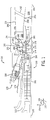
turbine bucket section 178 of theturbine section 130 includes aclearance 194 between ends of a plurality of last turbine bucket blades 195 (e.g., thelast blade 180 of the gas turbine section 130) and astationary shroud 196 disposed about the plurality of lastturbine bucket blades 195. Further, anouter wall 198 of theexhaust diffuser system 188 extends from thestationary shroud 196. Astrut 200 is illustrated abutting theouter wall 198.Struts 200 are used to support the structure of theexhaust diffuser section 188. - As illustrated, a
manway 202 extends between theouter wall 198 and aninner wall 204 of theexhaust diffuser system 188. In certain embodiments, themanway 202 may encompass pipes or tubes that are used to transport fluids from outside theexhaust diffuser system 188 for use within theexhaust diffuser system 188. Theinner wall 204 is formed by the outside of an access tunnel or convergingpassageway 206. In certain embodiments, theinner wall 204 may extend at anangle 205 that is not parallel to thecentral axis 105. For example, theangle 205 between theinner wall 204 and thecentral axis 105 may be approximately 5 to 10 degrees, 3 to 7 degrees, or 8 to 15 degrees. As described in greater detail below, themanway 202 extends through theexhaust diffuser system 188 at an angle that is not perpendicular to thecentral axis 105. When exhaust (e.g., the exhaust combustion gases from the gas turbine section 130) flows through theexhaust diffuser system 188, the exhaust flow is directed around themanway 202 to exit theexhaust diffuser system 188. As such, themanway 202 may cause vortex shedding to occur. However, the amplitude and frequency of the vortex shedding may be lower in the present embodiments than in systems withmanways 202 that are perpendicular to thecentral axis 105. Thus, there may be a decrease in pressure loss, a decrease in noise, and an increase in overall diffuser performance in the present embodiments when compared to systems withmanways 202 that are perpendicular to thecentral axis 105. -
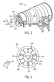
FIG. 2 is a perspective view of an embodiment of the gas turbineexhaust diffuser system 188. In particular, thestruts 200 are disposed around theinner wall 204 of theexhaust diffuser system 188 and extend radially 104 from theinner wall 204 to theouter wall 198 of theexhaust diffuser system 188 and thereby structurally support theouter wall 198 of theexhaust diffuser system 188. When turbine exhaust flows into theexhaust diffuser system 188, the exhaust flows through an area between theinner wall 204 and theouter wall 198. Thus, the exhaust flows around thestruts 200, which alters the exhaust flow. Therefore, the properties of how the exhaust flows through theexhaust diffuser system 188 are affected by the shape and position of thestruts 200. Further within theexhaust diffuser system 188, the exhaust flows around one or more manways 202. Again, the properties of how the exhaust flows through theexhaust diffuser system 188 are affected by the shape and position of themanways 202, as will be described in greater detail below.FIG. 3 is a side view of an embodiment of the gas turbineexhaust diffuser system 188.FIG. 3 illustrates howmultiple struts 200 may be arranged around theinner wall 204 of theexhaust diffuser system 188. Further, themanways 202 are located behind the struts 200 (within the exhaust diffuser system 188). As illustrated, themanways 202 also extend between theinner wall 204 and theouter wall 198 and may provide further support between theinner wall 204 and theouter wall 198. In particular, threemanways 202 are illustrated, however, other embodiments of theexhaust diffuser system 188 may have fewer or more manways 202. -
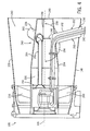
FIG. 4 is a cross-sectional side view of an embodiment of the gas turbineexhaust diffuser system 188. In particular, twomanways 202 are depicted, afirst manway 236 and a second manway 238. As previously described, themanways 202 extend from theouter wall 198 to theinner wall 204 and extend through anexhaust flow area 240 through which the turbine exhaust from theturbine section 130 flows. Although themanways 202 are illustrated as having a generally race-track shaped wall, themanways 202 walls may have any suitable shape (e.g., cylindrical, airfoil, etc.). Further, the shape of themanways 202 may be designed to achieve optimal flow of exhaust around themanways 202. In certain embodiments,pipes manways 202 and extend from themanways 202 into theaccess tunnel 206 defined within theinner wall 204 of theexhaust diffuser system 188. As discussed above, thepipes exhaust diffuser system 188. For example, thepipe 241 may be used to transport lubricating fluid (e.g., oil) through themanway 236 to theaccess tunnel 206 to be used by the exhaust diffuser system 188 (e.g., to lubricate bearings). As another example, thepipe 242 may be used to transport cooling air or fluid through the manway 238 to theaccess tunnel 206 to be used for reducing the temperature of components within theexhaust diffuser system 188. - The
pipes access tunnel 206 from an entry location 243 (e.g., where themanways 202 intersect with the access tunnel 206) toward astrut region 244 of theaccess tunnel 206. As illustrated, theaccess tunnel 206 forms a cone like shape which generally increases in diameter as theaccess tunnel 206 extends from theentry location 243 toward thestrut region 244. Therefore, adistance 246 between thepipes entry location 243 of thepipes access tunnel 206. As may be appreciated, thedistance 246 between thepipes pipes distance 246 as well as the distances between thepipes inner wall 204 may affect the ability of an operator to move through theaccess tunnel 206, such as to perform maintenance. As such, in certain embodiments, themanways 202 extend at an angle from theouter wall 198 toward theinner wall 204 that is not perpendicular to thecentral axis 105. By extending themanways 202 at an angle not perpendicular to thecentral axis 105, the location of themanways 202 may cause thepipes access tunnel 206 at a location where theaccess tunnel 206 has a larger diameter than if themanways 202 extended toward theaccess tunnel 206 at an angle perpendicular to thecentral axis 105, assuming that themanways 202 extend from the same location of theouter wall 198 in both instances. As a result, thedistance 246 may increase and allow more space for an operator to move within theaccess tunnel 206. For example, thedistance 246 may increase because thepipes entry location 243 where theaccess tunnel 206 has a larger diameter than in other entry locations. The larger diameter enables thepipes greater distance 246 from each other as they extend into theaccess tunnel 206, remain close to theinner wall 204, and extend toward thestrut region 244. In certain embodiments, heat transfer between thepipes distance 246 increases. - An
entry distance 248 is the distance between thepipes access tunnel 206. As may be appreciated, as theentry distance 248 increases, there is greater space for the operator to enter theaccess tunnel 206 through theaccess door 249. Theentry distance 248 is greater in the present embodiments than in systems where themanways 202 extend perpendicular to thecentral axis 105, again assuming that themanways 202 extend from the same location of theouter wall 198 in both instances. - There are generally two sides of each
manway 202. Specifically, an upstream end 250 (e.g., the side of themanway 202 closest to the struts 200) and a downstream end 252 (e.g., the side of themanway 202 farthest from the struts 200). As illustrated, the angle between themanways 202 and thecentral axis 105 may be described using an upstream angle 254 (e.g., the angle between theupstream end 250 and the central axis 105) or a downstream angle 256 (e.g., the angle between thedownstream end 252 of themanway 202 and the central axis 105). Theupstream angle 254 may be any suitable angle greater than 90 degrees (e.g., not perpendicular), and thedownstream angle 256 may be any suitable angle less than 90 degrees (e.g., not perpendicular). For example, theupstream angle 254 may be within a range of approximately 95 to 115 degrees, 93 to 105 degrees, or 100 to 120 degrees. Specifically, theupstream angle 254 may be approximately 105 degrees. On the other hand, thedownstream angle 256 may be within a range of approximately 65 to 85 degrees, 75 to 87 degrees, or 60 to 80 degrees. In particular, thedownstream angle 256 may be approximately 85 degrees. Further, theupstream angle 254 and thedownstream angle 256 are supplementary angles (i.e., they combine to equal 180 degrees). - As described above, during operation of the
gas turbine engine 100, exhaust flows through theexhaust diffuser system 188. The exhaust enters theexhaust diffuser system 188, flows around thestruts 200, then flows through theexhaust flow area 240 and around themanways 202 before the exhaust exits theexhaust diffuser system 188. As such, themanways 202 may cause vortex shedding to occur. However, the amplitude and frequency of the vortex shedding may be lower than in systems withmanways 202 that are perpendicular to thecentral axis 105. More specifically, because themanways 202 are angled away from the impinging flow of the exhaust, the amplitude and frequency of vortex shedding may be drastically reduced as compared toperpendicular manways 202. - In summary, the technical effects of the present invention include providing greater access for an operator to enter and maneuver within the
access tunnel 206. Further, heat transfer between pipes within theaccess tunnel 206 is decreased as the pipes are moved away from each other within theaccess tunnel 206. In addition, the amplitude and frequency of the vortex shedding is decreased (e.g., the flow of exhaust through theexhaust diffuser system 188 is disturbed less). As a result, there may be a decrease in pressure loss, a decrease in noise, and an increase in overall diffuser performance in the present embodiments when compared to systems withmanways 202 that are perpendicular to thecentral axis 105. - This written description uses examples to disclose the invention, including the best mode, and also to enable any person skilled in the art to practice the invention, including making and using any devices or systems and performing any incorporated methods. The patentable scope of the invention is defined by the claims, and may include other examples that occur to those skilled in the art. Such other examples are intended to be within the scope of the claims if they have structural elements that do not differ from the literal language of the claims, or if they include equivalent structural elements with insubstantial differences from the literal languages of the claims.
Claims (13)
- A turbine exhaust diffuser system (188), comprising:an outer wall (198);an inner wall (204) formed by a converging inner passageway (206), wherein turbine exhaust is configured to flow through an area between the outer wall (198) and the inner wall (204); andat least one manway (202) extending from the outer wall (198) to the inner wall (204), wherein the at least one manway (202) extends from the outer wall (198) to the inner wall (204) at an angle (254) that is not perpendicular to a central axis (105) of the turbine exhaust diffuser system (188).
- The turbine exhaust diffuser system of claim 1, wherein the angle (254) at between the at least one manway (202) and the central axis (105) is greater than approximately 95 degrees.
- The turbine exhaust diffuser system of claim 1 or 2, wherein the angle (254) between the at least one manway (202) and the central axis (105) is between approximately 100 and approximately 115 degrees.
- The turbine exhaust diffuser system of claim 1, comprising a plurality of manways (202) extending from the outer wall (198) to the inner wall (204), wherein each of the plurality of manways (238) extends from the outer wall (198) to the inner wall (204) at an angle that is not perpendicular to the central axis (105) of the turbine exhaust system (188).
- The turbine exhaust diffuser system of claim 4, wherein the plurality of manways (202) comprises a first manway (236), a second manway (238), and a third manway.
- The turbine exhaust diffuser system of claim 5, wherein the angles (256) between the first (236), second (238), and third manways (202) and the central axis (105) are between approximately 95 and approximately 115 degrees.
- The turbine exhaust diffuser system of claim 5 or 6, wherein the second manway (236) comprises pipes (241) for providing lubricating fluid to a turbine.
- The turbine exhaust diffuser system of claim 5, 6 or 7, wherein the third manway (238) comprises pipes (242) for providing cooling fluid to a turbine.
- The turbine exhaust diffuser system of any preceding claim, wherein the converging passageway (206) is configured to allow an operator to enter the converging passageway (206) through an access door (249) and move within the converging passage (206).
- The turbine exhaust diffuser system of claim 9, wherein the converging passageway (206) comprises a conical shape having a smaller interior diameter toward a downstream (244) end of the converging passageway (206).
- The turbine exhaust diffuser system of any of claims 4, 9 or 10, wherein each of the plurality of manways (202) comprises an upstream end (250) and a downstream end (252), the manway (202) forming a first angle (254) between the upstream end (250) and the central axis (105) and a second angle (256) between the downstream end (252) and the central axis (105).
- The turbine exhaust diffuser system of claim 11, wherein the first angle (254) is greater than the second angle (256).
- The turbine exhaust diffuser system of claim 11 or 12, wherein the first angle (254) is between 95 and 110 degrees and the second angle (256) is between 70 and 85 degrees.
Applications Claiming Priority (1)
| Application Number | Priority Date | Filing Date | Title |
|---|---|---|---|
| PL397899A PL221113B1 (en) | 2012-01-25 | 2012-01-25 | Turbine exhaust diffuser system |
Publications (1)
| Publication Number | Publication Date |
|---|---|
| EP2620596A2 true EP2620596A2 (en) | 2013-07-31 |
Family
ID=47631305
Family Applications (1)
| Application Number | Title | Priority Date | Filing Date |
|---|---|---|---|
| EP13152397.9A Withdrawn EP2620596A2 (en) | 2012-01-25 | 2013-01-23 | Turbine exhaust diffuser system |
Country Status (6)
| Country | Link |
|---|---|
| US (1) | US20130189088A1 (en) |
| EP (1) | EP2620596A2 (en) |
| JP (1) | JP2013151934A (en) |
| CN (1) | CN103225520A (en) |
| PL (1) | PL221113B1 (en) |
| RU (1) | RU2013102779A (en) |
Families Citing this family (6)
| Publication number | Priority date | Publication date | Assignee | Title |
|---|---|---|---|---|
| FR2997997B1 (en) * | 2012-11-12 | 2014-12-26 | Snecma | AIR TUBE SUPPORT SUPPORT IN A TURBOMACHINE |
| FR2997996B1 (en) * | 2012-11-12 | 2015-01-09 | Snecma | AIR TUBE SUPPORT SUPPORT IN A TURBOMACHINE |
| US10255406B2 (en) * | 2015-02-24 | 2019-04-09 | Siemens Corporation | Designing the geometry of a gas turbine exhaust diffuser on the basis of fluid dynamics information |
| US10563543B2 (en) | 2016-05-31 | 2020-02-18 | General Electric Company | Exhaust diffuser |
| US10612420B2 (en) * | 2016-11-17 | 2020-04-07 | General Electric Company | Support structures for rotors |
| CN109630219B (en) * | 2018-12-16 | 2022-03-04 | 中国航发沈阳发动机研究所 | Gas turbine exhaust apparatus |
Family Cites Families (13)
| Publication number | Priority date | Publication date | Assignee | Title |
|---|---|---|---|---|
| US2655307A (en) * | 1947-06-11 | 1953-10-13 | Gen Electric | Gas turbine rotor arrangement |
| GB695482A (en) * | 1950-11-28 | 1953-08-12 | Rolls Royce | Improvements in or relating to gas-turbine engines |
| GB846329A (en) * | 1957-12-12 | 1960-08-31 | Napier & Son Ltd | Combustion turbine power units |
| CH672004A5 (en) * | 1986-09-26 | 1989-10-13 | Bbc Brown Boveri & Cie | |
| US5404713A (en) * | 1993-10-04 | 1995-04-11 | General Electric Company | Spillage drag and infrared reducing flade engine |
| US20040109756A1 (en) * | 2002-12-09 | 2004-06-10 | Mitsubishi Heavy Industries Ltd. | Gas turbine |
| US6866479B2 (en) * | 2003-05-16 | 2005-03-15 | Mitsubishi Heavy Industries, Ltd. | Exhaust diffuser for axial-flow turbine |
| US20080159856A1 (en) * | 2006-12-29 | 2008-07-03 | Thomas Ory Moniz | Guide vane and method of fabricating the same |
| US8438859B2 (en) * | 2008-01-08 | 2013-05-14 | Rolls-Royce North American Technologies, Inc. | Integrated bypass engine structure |
| US8408011B2 (en) * | 2009-04-30 | 2013-04-02 | Pratt & Whitney Canada Corp. | Structural reinforcement strut for gas turbine case |
| US20130091865A1 (en) * | 2011-10-17 | 2013-04-18 | General Electric Company | Exhaust gas diffuser |
| US9032721B2 (en) * | 2011-12-14 | 2015-05-19 | Siemens Energy, Inc. | Gas turbine engine exhaust diffuser including circumferential vane |
| US9316108B2 (en) * | 2012-03-05 | 2016-04-19 | General Electric Company | Gas turbine frame stiffening rails |
-
2012
- 2012-01-25 PL PL397899A patent/PL221113B1/en unknown
- 2012-03-26 US US13/430,603 patent/US20130189088A1/en not_active Abandoned
-
2013
- 2013-01-21 JP JP2013007964A patent/JP2013151934A/en active Pending
- 2013-01-23 EP EP13152397.9A patent/EP2620596A2/en not_active Withdrawn
- 2013-01-23 RU RU2013102779/06A patent/RU2013102779A/en not_active Application Discontinuation
- 2013-01-25 CN CN2013100287242A patent/CN103225520A/en active Pending
Non-Patent Citations (1)
| Title |
|---|
| None |
Also Published As
| Publication number | Publication date |
|---|---|
| PL397899A1 (en) | 2013-08-05 |
| RU2013102779A (en) | 2014-07-27 |
| US20130189088A1 (en) | 2013-07-25 |
| JP2013151934A (en) | 2013-08-08 |
| CN103225520A (en) | 2013-07-31 |
| PL221113B1 (en) | 2016-02-29 |
Similar Documents
| Publication | Publication Date | Title |
|---|---|---|
| US20120034064A1 (en) | Contoured axial-radial exhaust diffuser | |
| EP2975213B1 (en) | Gas turbine engine with vaneless transition duct | |
| EP2620596A2 (en) | Turbine exhaust diffuser system | |
| EP3244011A2 (en) | System for cooling seal rails of tip shroud of turbine blade | |
| US10041534B2 (en) | Bearing outer race retention during high load events | |
| US11085309B2 (en) | Outer drum rotor assembly | |
| EP3045668B1 (en) | Cooling passages for a mid-turbine frame | |
| US20220106907A1 (en) | Turbine engine with struts | |
| US10196980B2 (en) | Bearing outer race retention during high load events | |
| CN104169529A (en) | Arrangement for delivering combustion gas | |
| US20150345301A1 (en) | Rotor blade cooling flow | |
| US10577940B2 (en) | Turbomachine rotor blade | |
| US10422533B2 (en) | Combustor with axially staged fuel injector assembly | |
| US20140137533A1 (en) | Exhaust gas diffuser for a gas turbine | |
| US8628297B2 (en) | Tip flowpath contour | |
| US8591184B2 (en) | Hub flowpath contour | |
| JP2015526691A (en) | Gas turbine engine having a shortened middle section | |
| US20190170004A1 (en) | Fluid collection gutter for a geared turbine engine | |
| WO2019027661A1 (en) | Gas turbine exhaust diffuser having flow guiding elements | |
| US9447794B2 (en) | Inducer and diffuser configuration for a gas turbine system | |
| EP2578815A2 (en) | Exhaust gas diffuser | |
| EP3241989A1 (en) | A gas turbine section with improved strut design | |
| US9284853B2 (en) | System and method for integrating sections of a turbine | |
| US20190353054A1 (en) | Exhaust system for a gas turbine engine | |
| US11773750B2 (en) | Turbomachine component retention |
Legal Events
| Date | Code | Title | Description |
|---|---|---|---|
| PUAI | Public reference made under article 153(3) epc to a published international application that has entered the european phase |
Free format text: ORIGINAL CODE: 0009012 |
|
| AK | Designated contracting states |
Kind code of ref document: A2 Designated state(s): AL AT BE BG CH CY CZ DE DK EE ES FI FR GB GR HR HU IE IS IT LI LT LU LV MC MK MT NL NO PL PT RO RS SE SI SK SM TR |
|
| AX | Request for extension of the european patent |
Extension state: BA ME |
|
| STAA | Information on the status of an ep patent application or granted ep patent |
Free format text: STATUS: THE APPLICATION IS DEEMED TO BE WITHDRAWN |
|
| 18D | Application deemed to be withdrawn |
Effective date: 20160802 |