EP2613017A2 - Working fluid sensor system for power generation system - Google Patents
Working fluid sensor system for power generation system Download PDFInfo
- Publication number
- EP2613017A2 EP2613017A2 EP12197938.9A EP12197938A EP2613017A2 EP 2613017 A2 EP2613017 A2 EP 2613017A2 EP 12197938 A EP12197938 A EP 12197938A EP 2613017 A2 EP2613017 A2 EP 2613017A2
- Authority
- EP
- European Patent Office
- Prior art keywords
- working fluid
- turbine
- sensors
- flowpath
- computing device
- Prior art date
- Legal status (The legal status is an assumption and is not a legal conclusion. Google has not performed a legal analysis and makes no representation as to the accuracy of the status listed.)
- Withdrawn
Links
- 239000012530 fluid Substances 0.000 title claims abstract description 130
- 238000010248 power generation Methods 0.000 title claims abstract description 15
- 239000000523 sample Substances 0.000 claims abstract description 98
- 238000000034 method Methods 0.000 claims description 38
- 230000003628 erosive effect Effects 0.000 claims description 27
- 230000008569 process Effects 0.000 claims description 27
- 238000004590 computer program Methods 0.000 claims description 13
- 239000011248 coating agent Substances 0.000 claims description 3
- 238000000576 coating method Methods 0.000 claims description 3
- 238000011084 recovery Methods 0.000 claims description 3
- 238000004458 analytical method Methods 0.000 description 14
- 238000010586 diagram Methods 0.000 description 9
- 230000006870 function Effects 0.000 description 8
- 238000013461 design Methods 0.000 description 7
- 230000003746 surface roughness Effects 0.000 description 7
- 238000005259 measurement Methods 0.000 description 6
- 238000012360 testing method Methods 0.000 description 6
- 238000012423 maintenance Methods 0.000 description 5
- 230000003287 optical effect Effects 0.000 description 5
- 230000036961 partial effect Effects 0.000 description 5
- XLYOFNOQVPJJNP-UHFFFAOYSA-N water Substances O XLYOFNOQVPJJNP-UHFFFAOYSA-N 0.000 description 5
- 238000003780 insertion Methods 0.000 description 4
- 230000037431 insertion Effects 0.000 description 4
- 238000004519 manufacturing process Methods 0.000 description 4
- 238000012545 processing Methods 0.000 description 4
- 238000000605 extraction Methods 0.000 description 3
- 238000004364 calculation method Methods 0.000 description 2
- 238000006243 chemical reaction Methods 0.000 description 2
- 238000004891 communication Methods 0.000 description 2
- 230000000875 corresponding effect Effects 0.000 description 2
- 230000000694 effects Effects 0.000 description 2
- 230000003993 interaction Effects 0.000 description 2
- 238000009533 lab test Methods 0.000 description 2
- 230000000670 limiting effect Effects 0.000 description 2
- 239000013307 optical fiber Substances 0.000 description 2
- 238000013459 approach Methods 0.000 description 1
- 230000008901 benefit Effects 0.000 description 1
- 230000005540 biological transmission Effects 0.000 description 1
- 230000000295 complement effect Effects 0.000 description 1
- 230000002596 correlated effect Effects 0.000 description 1
- 238000007405 data analysis Methods 0.000 description 1
- 230000003247 decreasing effect Effects 0.000 description 1
- 230000003111 delayed effect Effects 0.000 description 1
- 238000002405 diagnostic procedure Methods 0.000 description 1
- 238000006073 displacement reaction Methods 0.000 description 1
- 238000007689 inspection Methods 0.000 description 1
- 238000012538 light obscuration Methods 0.000 description 1
- 238000012544 monitoring process Methods 0.000 description 1
- 230000000644 propagated effect Effects 0.000 description 1
- 238000011002 quantification Methods 0.000 description 1
- 230000002441 reversible effect Effects 0.000 description 1
- 239000004065 semiconductor Substances 0.000 description 1
- 238000012546 transfer Methods 0.000 description 1
Images






Classifications
-
- F—MECHANICAL ENGINEERING; LIGHTING; HEATING; WEAPONS; BLASTING
- F01—MACHINES OR ENGINES IN GENERAL; ENGINE PLANTS IN GENERAL; STEAM ENGINES
- F01D—NON-POSITIVE DISPLACEMENT MACHINES OR ENGINES, e.g. STEAM TURBINES
- F01D17/00—Regulating or controlling by varying flow
- F01D17/02—Arrangement of sensing elements
- F01D17/08—Arrangement of sensing elements responsive to condition of working-fluid, e.g. pressure
-
- F—MECHANICAL ENGINEERING; LIGHTING; HEATING; WEAPONS; BLASTING
- F01—MACHINES OR ENGINES IN GENERAL; ENGINE PLANTS IN GENERAL; STEAM ENGINES
- F01D—NON-POSITIVE DISPLACEMENT MACHINES OR ENGINES, e.g. STEAM TURBINES
- F01D25/00—Component parts, details, or accessories, not provided for in, or of interest apart from, other groups
- F01D25/007—Preventing corrosion
-
- Y—GENERAL TAGGING OF NEW TECHNOLOGICAL DEVELOPMENTS; GENERAL TAGGING OF CROSS-SECTIONAL TECHNOLOGIES SPANNING OVER SEVERAL SECTIONS OF THE IPC; TECHNICAL SUBJECTS COVERED BY FORMER USPC CROSS-REFERENCE ART COLLECTIONS [XRACs] AND DIGESTS
- Y02—TECHNOLOGIES OR APPLICATIONS FOR MITIGATION OR ADAPTATION AGAINST CLIMATE CHANGE
- Y02E—REDUCTION OF GREENHOUSE GAS [GHG] EMISSIONS, RELATED TO ENERGY GENERATION, TRANSMISSION OR DISTRIBUTION
- Y02E20/00—Combustion technologies with mitigation potential
- Y02E20/16—Combined cycle power plant [CCPP], or combined cycle gas turbine [CCGT]
Definitions
- the subject matter disclosed herein relates to power plant systems and, more particularly, to working fluid sensor systems for analyzing the operation, performance, and/or efficiency of turbines and power generation systems.
- Some power plant systems for example certain nuclear, simple-cycle and combined-cycle power plant systems, employ turbines in their design and operation. Analysis of the operation and performance of some of these systems and turbines (e.g., steam turbines, low pressure steam turbines, etc.) may be assisted and/or performed by analyzing a moisture content of a working fluid (e.g., exhaust steam) in the turbine. This analysis may enable technicians and/or designers to make more informed decisions with regard to maintenance, design adjustments and plant operations (e.g., which turbines to operate when, whether operational parameters need to be adjusted for a particular turbine, whether maintenance needs to be performed for a particular turbine, etc.).
- a working fluid e.g., exhaust steam
- the measured moisture content of the LP turbine exhaust steam may be used along with data on the LP turbine exhaust pressure, LP turbine inlet pressure and LP turbine operating temperatures, to calculate the LP turbine efficiency. Therefore, it is desirable to quickly, accurately and reliably measure the moisture content within the turbine, particularly in the turbine exhaust.
- Some power plant systems rely on extracting and analyzing exhaust steam samples to determine a moisture content of the working fluid in the turbine.
- Other systems have attempted to employ optical sensors using light extinction theory to determine a moisture content of the exhaust steam.
- samples may be difficult to obtain and test, and installing, calibrating and operating optical sensors may not be economically possible or efficient. Thus, these systems may be imprecise, time consuming, technically complicated and/or not feasible.
- a working fluid sensor system includes: a set of sensors adapted to be disposed within a turbine, the set of sensors including probe portions which extend into a flowpath of the turbine for exposure to a working fluid, the probe portions adapted to react to a force exerted by the working fluid on the probe portions and indicate a moisture content of the working fluid.
- a first aspect of the invention provides a system including: a set of sensors adapted to be disposed within a turbine, the set of sensors including probe portions which extend into a flowpath of the turbine for exposure to a working fluid, the probe portions adapted to react to a force exerted by the working fluid on the probe portions and indicate a moisture content of the working fluid.
- a second aspect of the invention provides a system including: at least one computing device adapted to determine an operational characteristic of a turbine by performing actions comprising: obtaining flow data from a set of sensors exposed to a flow of a working fluid in the turbine, the flow data including at least one of: a drag coefficient on the set of sensors, a set of current ambient conditions at the turbine, or an erosive effect of the working fluid on the set of sensors; determining a moisture content of the working fluid based upon the flow data; and determining an operational characteristic for the turbine based on the moisture content of the working fluid.
- a third aspect of the invention provides a combined cycle power generation system including: a gas turbine; a heat recovery steam generator (HRSG) operatively connected to the gas turbine; a steam turbine operatively connected to the HRSG; a generator operatively connected to at least one of the gas turbine or the steam turbine; and a set of sensors adapted to be disposed within the steam turbine, the set of sensors including probe portions which extend into a flowpath of the steam turbine for exposure to a working fluid, the probe portions adapted to react to a force exerted by the working fluid on the probe portions and indicate a moisture content of the working fluid.
- HRSG heat recovery steam generator
- aspects of the invention provide for systems configured to analyze operation of a turbine by obtaining and processing a flow data set (e.g., a drag coefficient on a set of sensors, a temperature of a working fluid, a set of current ambient conditions at the turbine, an erosive effect of the working fluid on the set of sensors, moisture content values, etc.) for a working fluid (e.g., steam) in the turbine.
- a flow data set e.g., a drag coefficient on a set of sensors, a temperature of a working fluid, a set of current ambient conditions at the turbine, an erosive effect of the working fluid on the set of sensors, moisture content values, etc.
- a working fluid e.g., steam
- These systems include a set of sensors disposed in a flowpath of the turbine so as to interact with a working fluid and obtain data flow values for the flow data set (e.g., a drag coefficient on a set of sensors, a temperature of a working fluid, a set of current ambient conditions at the turbine, an erosive effect of the working fluid on the set of sensors, moisture content values, etc.), these values then being analyzed to evaluate turbine operations.
- data flow values for the flow data set e.g., a drag coefficient on a set of sensors, a temperature of a working fluid, a set of current ambient conditions at the turbine, an erosive effect of the working fluid on the set of sensors, moisture content values, etc.
- Design and operation of some power generation systems may include component maintenance and/or regulation and incremental adjustment of a number of operating parameters. Adjustment of operational parameters and/or performance of maintenance operations may be governed by an efficiency of the system and/or components (e.g., turbines within the system).
- a moisture content measurement of a working fluid in a given turbine may enable a direct, real-time determination of the efficiency/performance characteristics of the turbine.
- current systems do not have a quick, routine, and/or accurate way to measure moisture content in the turbine. This lack of accurate and reliable moisture content measurement and turbine efficiency analysis; may result in non-optimized designs, delayed and improper maintenance operations and a decreased efficiency of the system.
- embodiments of the current invention provide for a system which accurately and reliably analyzes turbine operation.
- the system extends a set of sensors into the flowpath of a working fluid in the turbine, thereby directly exposing the set of sensors to the working fluid and causing the set of sensors to react to the working fluid.
- the reaction e.g., surface erosion, drag coefficient, etc.
- the reaction e.g., surface erosion, drag coefficient, etc.
- Analysis of the flow data set determines a moisture content of the working fluid and the related turbine performance levels.
- the system described herein may be embodied as a system(s), method(s), operator display (s) or computer program product(s), e.g., as part of a power plant system, a power generation system, a turbine system, etc.
- embodiments of the present invention may take the form of an entirely hardware embodiment, an entirely software embodiment (including firmware, resident software, micro-code, etc.) or an embodiment combining software and hardware aspects that may all generally be referred to herein as a "circuit,” “module,” “network” or “system.”
- the present invention may take the form of a computer program product embodied in any tangible medium of expression having computer-usable program code embodied in the medium.
- the computer-usable or computer-readable medium may be, for example but not limited to, an electronic, magnetic, optical, electromagnetic, infrared, or semiconductor system, apparatus, or device. More specific examples (a non-exhaustive list) of the computer-readable medium would include the following: an electrical connection having one or more wires, a portable computer diskette, a hard disk, a random access memory (RAM), a read-only memory (ROM), an erasable programmable read-only memory (EPROM or Flash memory), an optical fiber, a portable compact disc read-only memory (CD-ROM), an optical storage device, a transmission media such as those supporting the Internet or an intranet, or a magnetic storage device.
- the computer-usable or computer-readable medium could even be paper or another suitable medium upon which the program is printed, as the program can be electronically captured, via, for instance, optical scanning of the paper or other medium, then compiled, interpreted, or otherwise processed in a suitable manner, if necessary, and then stored in a computer memory.
- a computer-usable or computer-readable medium may be any medium that can contain, store, communicate, or transport the program for use by or in connection with the instruction execution system, apparatus, or device.
- the computer-usable medium may include a propagated data signal with the computer-usable program code embodied therewith, either in baseband or as part of a carrier wave.
- the computer usable program code may be transmitted using any appropriate medium, including but not limited to wireless, wireline, optical fiber cable, RF, etc.
- Computer program code for carrying out operations of the present invention may be written in any combination of one or more programming languages, including an object oriented programming language such as Java, Smalltalk, C++ or the like and conventional procedural programming languages, such as the "C" programming language or similar programming languages.
- the program code may execute entirely on the user's computer, partly on the user's computer, as a stand-alone software package, partly on the user's computer and partly on a remote computer or entirely on the remote computer or server.
- the remote computer may be connected to the user's computer through any type of network, including a local area network (LAN) or a wide area network (WAN), or the connection may be made to an external computer (for example, through the Internet using an Internet Service Provider).
- LAN local area network
- WAN wide area network
- Internet Service Provider for example, AT&T, MCI, Sprint, EarthLink, MSN, GTE, etc.
- These computer program instructions may also be stored in a computer-readable medium that can direct a computer or other programmable data processing apparatus to function in a particular manner, such that the instructions stored in the computer-readable medium produce an article of manufacture including instruction means which implement the function/act specified in the block diagram block or blocks.
- the computer program instructions may also be loaded onto a computer or other programmable data processing apparatus to cause a series of operational steps to be performed on the computer or other programmable apparatus to produce a computer implemented process such that the instructions which execute on the computer or other programmable apparatus provide processes for implementing the functions/acts specified in the flowchart and/or block diagram block or blocks.
- FIG. 1 an illustrative environment 100 including portions of a turbine 110 (e.g., a steam turbine) is shown according to embodiments of the invention.
- Turbine 110 may include a working fluid sensor system 120 which is communicatively connected to a flowpath 117 in turbine 110.
- Working fluid sensor system 120 may include a computing device 122 connected to a set of sensors 140 disposed within flowpath 117.
- Set of sensors 140 include a probe portion 142 which is exposed to/interacts with a working fluid 107 in flowpath 117.
- Computing device 122 is configured to monitor and/or analyze the interaction between working fluid 107 and set of sensors 140, and generate a flow data set based on this interaction.
- set of sensors 140 may include any number or combination of probe portions 142 (e.g., circular cylinders, airfoils, etc.) connected to turbine 110 and adapted to extend into/obstruct a portion of flowpath 117. These probe portions 142 may be adapted to be extendable and removable from flowpath 117 and to contact working fluid 107 during operation of turbine 110. In one embodiment, probe portions 142 may be inserted into flowpath 117 once operation of turbine 110 has been stabilized at a design point condition (e.g., a specific load, a specific speed, etc.). The reaction (e.g., erosion, displacement, etc.) of probe portions 142 to exposure to and/or a force exerted by working fluid 107 may be used to develop the flow data set and/or determine a moisture content of working fluid 107.
- probe portions 142 e.g., circular cylinders, airfoils, etc.
- probe portions 142 may be exposed to working fluid 107 for a pre-determined period of time and then removed and analyzed to develop the flow data set and determine the flow characteristics of working fluid 107 and/or the operational characteristics (e.g., moisture content of working fluid 107, operating condition of turbine 110, performance of turbine 110, etc.) of turbine 110.
- contact between working fluid 107 and set of sensors 140 may erode probe portions 142.
- set of sensors 140 may be weighed before and after exposure to working fluid 107, the difference in weights of set of sensors 140 before exposure to working fluid 107 and after exposure to working fluid 107 determining an erosion rate of probe portions 142. The determined erosion rate may then be used to calculate and/or determine a moisture content of working fluid 107.
- a roughness determination (e.g., a determination of the texture/surface roughness) of probe portions 142 may be made after exposure to working fluid 107. The roughness determination may then be compared to a known roughness for probe portions 142 from before exposure to working fluid 107 to determine an erosion rate of probe portions 142, and thus, determine the related moisture content of working fluid 107.
- set of sensors 140 may include sacrificial probes/specimens.
- set of sensors 140 may include a sacrificial/erosive coating disposed about at least a portion of set of sensors 140. In one embodiment, the erosive coating may have a low erosion resistance.
- set of sensors 140 may include an erosive sheath disposed about at least a portion of sensors 140. In one embodiment, the erosive sheath may have a low erosion resistance.
- set of sensors 140 may be adapted to determine a set of drag values (e.g., drag coefficients) on probe portions 142 exerted by flow of working fluid 107.
- computing device 122 may determine a moisture content of working fluid 107 based on the drag coefficients determined by set of sensors 140.
- set of sensors 140 may include a thermometer and a set of pressure transducers 187 (shown in phantom), and computing device 122 may include a load cell. Computing device 122 may process data obtained from the thermometer, set of pressure transducers 187 and the load cell to determine the drag coefficients for probe portions 142.
- a plurality of pressure transducers 187 may be disposed about a midspan of probe portions 142.
- set of pressure transducers 187 may be disposed within probe portions 142 and exposed to working fluid 107 via a set of ports 188 (shown in phantom) formed in probe portions 142.
- computing device 122 may determine a moisture content of working fluid 107 based on the differences in drag coefficient determined between each probe portion 142 in set of sensors 140.
- probe portions 142 may have varying shapes relative one another.
- computing device 122 may determine a moisture content of working fluid 107 based on an average of the drag coefficients determined by set of sensors 140.
- computing device 122 may be located external to turbine 110.
- computing device 122 may be remotely located (e.g., in a separate portion of a power generation plant, at a different geographical location, etc.) relative to a position of turbine 110.
- computing device 122 may be an internal component of turbine 110.
- set of sensors 140 may include any now known or later developed sensing device, including a combination of sensor devices, transducers, thermometers, etc. disposed throughout turbine 110.
- FIG. 2 a schematic partial cut-away view of portions of turbine 110 is shown defining a flowpath 117 according to embodiments. It is understood that elements similarly numbered between FIG. 1 and FIG. 2 may be substantially similar as described with reference to FIG. 1 . Further, in embodiments shown and described with reference to FIGS. 2-10 , like numbering may represent like elements. Redundant explanation of these elements has been omitted for clarity. Finally, it is understood that the components of FIGS. 1-10 and their accompanying descriptions may be applied to any embodiment described herein.
- turbine 110 may include a first probe sensor 142, a second probe sensor 144, and a scoop sensor 146 connected to portions of turbine 110 and in contact with a portion of flowpath 117.
- First probe sensor 142 is connected to a portion of turbine 110 and extends partially into flowpath 117.
- first probe sensor 142 may include an airfoil shape.
- first probe sensor 142 may include a cylindrical shape.
- Second probe sensor 144 is connected to multiple portions of turbine 110 and traverses/extends through a portion of flowpath 117 above a rotor 119. In one embodiment, second probe sensor 144 dissects flowpath 117 into separate portions.
- Scoop sensor 146 extends into a portion of flowpath 117 and has a cup or scoop like shape.
- scoop sensor 146 is adapted to capture a portion of working fluid 107 during operation of turbine 110. It is understood that any of first probe sensor 142, second probe sensor 144, scoop sensor 146 and/or set of sensors 140, may be attached to turbine 110 via any now know or later developed methods.
- a set of apertures may be formed in turbine 110 to enable insertion, extraction, and/or securing of first probe sensor 142, second probe sensor 144, scoop sensor 146 and/or set of sensors 140 in flowpath 117.
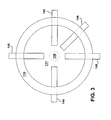
- set of sensors 140 include a plurality of sensors spaced about turbine 110 and extending into flowpath 117.
- set of sensors 140 include four sensors spaced circumferentially about flowpath 117.
- set of sensors 140 are spaced about equidistant about a circumference of flowpath 117.
- set of sensors 140 may be adapted to complement a low pressure diagnostic test approach with traverse probes and rakes, this set of sensors attaching to and or installing within existing apertures, brackets, and/or other hardware designed to secure testing components.
- set of sensors 140 first probe sensor 142, second probe sensor 144, and scoop sensor 146 are shown disposed within flowpath 117 at specific angles, these sensors may be disposed at any angle, configuration, or orientation within turbine 110 and/or flowpath 117. Further, set of sensors 140 may include any number or combination of first probe sensor 142, second probe sensor 144, scoop sensor 146, or any other sensor or sensor shape now known or later developed.
- working fluid sensor system 121 includes a support bracket 154 which is connected to turbine 110 and is adapted to support a load cell 152 connected to a probe sensor 150.
- probe sensor 150 is exposed to a working fluid 107 by extension into a flowpath 117 defined by turbine 110. As working fluid 107 moves through flowpath 117 it exerts a force on probe sensor 150 which may be measured by load cell 152.
- load cell 152 may calculate a drag coefficient on probe sensor 150 based on the measured force.
- load cell 152 may transmit the force measurement to computing device 122 (shown in FIG.
- computing device 122 may determine an efficiency and/or at least one operational characteristic of turbine 110 based on the drag coefficient of probe sensor 150.
- working fluid sensor system 123 includes a scoop sensor 146 which is connected to turbine 110 via a scoop sensor base system 147.
- scoop sensor 146 is extended into a flowpath 117 defined by turbine 110 and exposed to a working fluid 107. As working fluid 107 moves through flowpath 117 it exerts a force on scoop sensor 146 which may be measured and/or analyzed by scoop sensor base system 147.
- scoop sensor 146 may capture an amount of water in working fluid 107 and convey the captured water to scoop sensor base system 147 for quantification and/or further analysis.
- scoop sensor base system 147 may determine a moisture content of working fluid 107 based on the amount of water captured by scoop sensor 146 and the duration of time that scoop sensor 146 is exposed to working fluid 107. In another embodiment, scoop sensor base system 147 may transmit a measurement of the amount of water captured by scoop sensor 146 to computing device 122 (shown in FIG. 7 ) which may process the measurement to determine a moisture content of working fluid 107. In another embodiment, scoop sensor base system 147 may calculate a drag coefficient on scoop sensor 146 based on the measured force. In another embodiment, scoop sensor base system 147 may transmit the force measurement to computing device 122 (shown in FIG. 7 ) which may process the measured force to determine a drag coefficient on scoop sensor 146, a related moisture content of working fluid 107 and/or any number of operational characteristics of turbine 110.
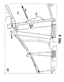
- working fluid sensor system 125 includes a base bracket 149 which is connected to turbine 110 and is adapted to support a transverse probe sensor 157.
- transverse probe sensor 157 is extended into flowpath 117 and exposed to working fluid 107. As working fluid 107 moves through flowpath 117 it exerts a force on transverse probe sensor 157 which erodes a surface of transverse probe sensor 157.
- transverse probe sensor 157 may traverse flowpath 117.
- base bracket 149 is adapted to secure transverse probe sensor 157 to turbine 110.
- base bracket 149 may be operable by a technician, thereby enabling insertion and extraction from flowpath 117.
- a technician may insert transverse probe sensor 157 into flowpath 117 for a predetermined period of time, then the technician may extract transverse probe sensor 157 for inspection.
- the technician may weigh transverse probe sensor 157 after exposure to working fluid 107 and compare this weight to a known weight of transverse probe sensor 157 prior to exposure to working fluid 107. The technician may then determine an erosion rate of transverse probe sensor 157 and a related moisture content of working fluid 107 based on the difference between the weights of transverse probe sensor 157 before and after exposure.
- the technician may determine a surface condition (e.g., roughness) of transverse probe sensor 157 after exposure to working fluid 107 and compare this surface condition to a known surface condition of transverse probe sensor 157 prior to exposure to working fluid 107. The technician may then use the difference between the surface conditions to determine an erosion rate of transverse probe sensor 157 and a related moisture content of working fluid 107. In one embodiment, the technician may determine a moisture content of working fluid 107 and/or efficiency of turbine 110 based on an erosion rate or surface roughness increase on transverse probe sensor 157 over time. In one embodiment, the technician may correlate/compare a measured erosion rate or surface roughness increase value to a set of erosion rates or surface roughness increase values which have been developed in a laboratory test facility.
- a surface condition e.g., roughness
- the developed values being obtained from a set of tests performed in a controlled environment on a comparable probe sensor.
- a calibration could be developed by use of LP turbine efficiency from a standard code test.
- computing device 122 may perform any of the analysis performed by the technician. Further, computing device 122 may be used to automate the use of transverse probe sensor 157, including extraction and insertion.
- FIG. 7 an illustrative environment 200 including a working fluid sensor system 124 is shown according to embodiments of the invention.
- Environment 200 includes a computer infrastructure 202 that can perform the various processes described herein.
- computer infrastructure 202 is shown including computing device 122 which includes working fluid sensor system 124, which enables computing device 122 to analyze operation of a turbine 110 by performing the process steps of the disclosure.
- computing device 122 may determine an efficiency and/or at least one operational characteristic of turbine 110 based on a drag coefficient for set of sensors 140.
- the computer software may include steam properties routines to enable calculation of the required thermodynamic variable necessary for LP turbine efficiency calculations.
- working fluid sensor system 124 has the technical effect of enabling computing device 122 to perform, among other things, the operational/working fluid analysis described herein. It is understood that some of the various components shown in FIG. 7 can be implemented independently, combined, and/or stored in memory for one or more separate computing devices that are included in computing device 122. Further, it is understood that some of the components and/or functionality may not be implemented, or additional schemas and/or functionality may be included as part of working fluid sensor system 124.
- Computing device 122 is shown including a memory 212, a processor unit (PU) 214, an input/output (I/O) interface 216, and a bus 218. Further, computing device 122 is shown in communication with an external I/O device/resource 220 and a storage system 222.
- PU 214 executes computer program code, such as working fluid sensor system 124, that is stored in memory 212 and/or storage system 222. While executing computer program code, PU 214 can read and/or write data, such as graphical user interface 230 and/or operational data 234, to/from memory 212, storage system 222, and/or I/O interface 216.
- Bus 218 provides a communications link between each of the components in computing device 122.
- I/O device 220 can comprise any device that enables a user to interact with computing device 122 or any device that enables computing device 122 to communicate with one or more other computing devices.
- Input/output devices (including but not limited to keyboards, displays, pointing devices, etc.) can be coupled to the system either directly or through intervening I/O controllers.
- environment 200 may optionally include a first probe sensor 242, a second probe sensor 244 and a scoop sensor 246 communicatively connected to turbine 110 and computing device 122 (e.g., via wireless or hard-wired means).
- First probe sensor 242, second probe sensor 244 and scoop sensor 246 may include any number of sensors as is known, including a thermometer, a humidity sensing device, gas turbine instruments, steam turbine instruments, etc.
- computing device 122 and/or working fluid sensor system 124 may be disposed upon or within turbine 110.
- computing device 122 can comprise any general purpose computing article of manufacture capable of executing computer program code installed by a user (e.g., a personal computer, server, handheld device, etc.). However, it is understood that computing device 122 is only representative of various possible equivalent computing devices and/or technicians that may perform the various process steps of the disclosure. To this extent, in other embodiments, computing device 122 can comprise any specific purpose computing article of manufacture comprising hardware and/or computer program code for performing specific functions, any computing article of manufacture that comprises a combination of specific purpose and general purpose hardware/software, or the like. In each case, the program code and hardware can be created using standard programming and engineering techniques, respectively. In one embodiment, computing device 122 may be/include a distributed control system.
- computing device 122 may be integral to a gas turbine. In another embodiment, computing device 122 may be integral to a steam turbine. In another embodiment, computing device 122 may be a part of power generation system 140. In one embodiment, computing device 122 may include a MARK VI controller. In another embodiment, computing device 122 may include a monitoring unit located proximate turbine 110 and a processing unit located remote to turbine 110.
- Fig. 8 an illustrative method flow diagram is shown according to embodiments of the invention:
- operation of turbine 110 is initiated and brought to a test level (e.g., a speed, a specific load, a set of specified operational parameters, etc.) for analysis by working fluid sensor system 124 and/or computing device 122.
- a test level e.g., a speed, a specific load, a set of specified operational parameters, etc.
- the operational parameters of turbine 110 may be selected from various steam temperatures, loads, or other operating parameter ranges and confined to steady operation within the selected ranges.
- the range of the selected turbine 110 operating condition(s) including but not necessarily limited to the designed optimal operational condition for turbine 110.
- the operational parameters of turbine 110 may be stabilized.
- the operational parameters of turbine 110 may be set to a base level and then varied during analysis. This testing process may be either an automatic/scheduled analysis of turbine 110, a condition dictated analysis of turbine 110 or a manual/user-commanded analysis of turbine 110.
- working fluid sensor system 124 is initiated and probe portions 142 of a set of sensors 140 are extended into a flowpath 117 in turbine 110. Extension and/or insertion into turbine 110 causes probe portions 142 to contact and react to working fluid 107 which is driven through flowpath 117 by operation of turbine 110.
- a technician and/or computing device 122 obtains a set of flow data for working fluid 107.
- Flow data may be obtained from at least one of: memory 212, storage system 222, and/or set of sensors 140.
- Flow data may include a temperature of working fluid 107, a pressure of working fluid 107, an erosion rate of probe portions 142, a drag coefficient for probe portions 142 in working fluid 107, etc.
- set of sensors 140 may be connected to a load cell 152 which obtains real-time and/or updated data values for working fluid 107.
- the technician and/or computing device 122 accesses flow characteristic data 235 (e.g.
- flow characteristic data 235 may be developed in an operating laboratory test turbine under controlled conditions to develop a comparable set of flow characteristic data 235 which may be correlated with obtained flow data 234.
- the moisture content of working fluid 107 may be determined by considering the drag coefficient of probe portions 142 to be a function of moisture content.
- the technician, computing device 122 and/or PU 214 may access any of: a drag coefficient look-up table, a pre-generated drag coefficient curve and/or stored drag coefficient data.
- the technician, computing device 122 and/or PU 214 may compare flow data set 234 to data points in any of the drag coefficient look-up table, the pre-generated drag coefficient curve and/or the stored drag coefficient data to determine a moisture content of working fluid 107.
- the technician, computing device 122 and/or PU 214 may determine an operating condition and/or efficiency of turbine 110 based on the determined moisture content of working fluid 107.
- probe portions 142 are left extended in flowpath 117 during operation of turbine 110 for a predetermined period of time (e.g., several minutes, hours, days, etc.). After probe portions 142 have been exposed for the predetermined period of time, probe portions 142 are withdrawn from flowpath 117. Withdrawal of probe portions 142 may be automated or manually performed by a technician. Further, probe portions 142 may be withdrawn simultaneously or individually. In one embodiment, each probe portion 142 in set of sensors 140 may be withdrawn incrementally over varying time periods. In any event, following process P2B, in process P3B, set of sensors 140 are analyzed to determine an effect of exposure to working fluid 107.
- a predetermined period of time e.g., several minutes, hours, days, etc.
- set of sensors 140 may be weighed after being withdrawn, this weight being compared to a known weight of set of sensors 140 prior to exposure to working fluid 107 to determine an amount of erosive loss suffered by set of sensors 140. This amount of erosive loss is then used to determine a related moisture content of working fluid 107.
- a surface roughness of probe portions 142 may be determined after being withdrawn. This surface roughness is compared to a known surface roughness for probe portions 142 prior to exposure to working fluid 107 to determine the erosive impact working fluid 107 had on probe portions 142. The determined erosive impact is then used to determine a related moisture content of working fluid 107.
- the technician, computing device 122 and/or PU 214 may determine an operating condition and/or efficiency of turbine 110 based on the determined moisture content of working fluid 107.
- the technician, computing device 122 and/or PU 214 updates any of memory 212, storage system 222 and/or flow characteristic data set 235 based upon readings from set of sensors 140.
- these real-time readings are used to update flow data set 234, calibrate prediction software, adjust operating conditions and/or turbine design specifications.
- These readings are saved in any of memory 212 and storage system 222 to enhance flow data analysis and turbine operation predictions by computing device 122. In one embodiment, these readings are factored into the analysis by computing device 122.
- each block in the flowchart or block diagrams may represent a module, segment, or portion of code, which comprises one or more executable instructions for implementing the specified logical function(s).
- the functions noted in the block may occur out of the order noted in the FIGURES. For example, two blocks shown in succession may, in fact, be executed substantially concurrently, or the blocks may sometimes be executed in the reverse order, depending upon the functionality involved.
- Combined-cycle power plant 500 may include, for example, a gas turbine 580 operably connected to a generator 570.
- Generator 570 and gas turbine 580 may be mechanically coupled by a shaft 515, which may transfer energy between a gas turbine 580 and generator 570.
- a heat exchanger 586 operably connected to gas turbine 580 and a steam turbine 592.
- Heat exchanger 586 may be fluidly connected to both gas turbine 580 and steam turbine 592 via conventional conduits (numbering omitted).
- Heat exchanger 586 may be a conventional heat recovery steam generator (HRSG), such as those used in conventional combined-cycle power systems.
- HRSG heat recovery steam generator
- HRSG 586 may use hot exhaust from gas turbine 580, combined with a water supply, to create steam which is fed to steam turbine 592.
- Steam turbine 592 may optionally be coupled to a second generator system 570 (via a second shaft 515). Any of generator system 570, gas turbine 580, HRSG 586, and steam turbine 592 may be operably connected to working fluid sensor system 124 via computing device 122 of FIG. 7 or other embodiments described herein. It is understood that generators 570 and shafts 515 may be of any size or type known in the art and may differ depending upon their application or the system to which they are connected. Common numbering of the generators and shafts is for clarity and does not necessarily suggest these generators or shafts are identical.
- Generator system 570 and second shaft 515 may operate substantially similarly to generator system 570 and shaft 515 described above.
- working fluid sensor system 124 may be used, via computing device 122 to monitor steam turbine 592.
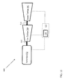
- a single-shaft combined-cycle power plant 600 may include a single generator 570 coupled to both gas turbine 580 and steam turbine 592 via a single shaft 515.
- Gas turbine 580 and steam turbine 592 may be operably connected to working fluid sensor system 124 via computing device 122 of FIG. 7 or other embodiments described herein.
- the working fluid sensor system of the present disclosure is not limited to any one power generation system, combined cycle power generation system, turbine or other system, and may be used with other power systems. Additionally, the system of the present invention may be used with other systems not described herein that may benefit from the operational analysis provided by the working fluid sensor system described herein.
- various systems and components are described as “obtaining” and/or “transferring” data (e.g., operational data, component temperatures, system specifications, etc.). It is understood that the corresponding data can be obtained using any solution.
- the corresponding system/component can generate and/or be used to generate the data, retrieve the data from one or more data stores or sensors (e.g., a database), receive the data from another system/component, and/or the like.
- the data is not generated by the particular system/component, it is understood that another system/component can be implemented apart from the system/component shown, which generates the data and provides it to the system/component and/or stores the data for access by the system/component.
Landscapes
- Engineering & Computer Science (AREA)
- Mechanical Engineering (AREA)
- General Engineering & Computer Science (AREA)
- Testing Of Devices, Machine Parts, Or Other Structures Thereof (AREA)
- Control Of Turbines (AREA)
- Engine Equipment That Uses Special Cycles (AREA)
Abstract
Description
- The subject matter disclosed herein relates to power plant systems and, more particularly, to working fluid sensor systems for analyzing the operation, performance, and/or efficiency of turbines and power generation systems.
- Some power plant systems, for example certain nuclear, simple-cycle and combined-cycle power plant systems, employ turbines in their design and operation. Analysis of the operation and performance of some of these systems and turbines (e.g., steam turbines, low pressure steam turbines, etc.) may be assisted and/or performed by analyzing a moisture content of a working fluid (e.g., exhaust steam) in the turbine. This analysis may enable technicians and/or designers to make more informed decisions with regard to maintenance, design adjustments and plant operations (e.g., which turbines to operate when, whether operational parameters need to be adjusted for a particular turbine, whether maintenance needs to be performed for a particular turbine, etc.). In systems incorporating a Low Pressure (LP) steam turbine the measured moisture content of the LP turbine exhaust steam may be used along with data on the LP turbine exhaust pressure, LP turbine inlet pressure and LP turbine operating temperatures, to calculate the LP turbine efficiency. Therefore, it is desirable to quickly, accurately and reliably measure the moisture content within the turbine, particularly in the turbine exhaust. Some power plant systems rely on extracting and analyzing exhaust steam samples to determine a moisture content of the working fluid in the turbine. Other systems have attempted to employ optical sensors using light extinction theory to determine a moisture content of the exhaust steam. However, samples may be difficult to obtain and test, and installing, calibrating and operating optical sensors may not be economically possible or efficient. Thus, these systems may be imprecise, time consuming, technically complicated and/or not feasible.
- Systems for analyzing operation of a power generation system are disclosed. In one embodiment, a working fluid sensor system includes: a set of sensors adapted to be disposed within a turbine, the set of sensors including probe portions which extend into a flowpath of the turbine for exposure to a working fluid, the probe portions adapted to react to a force exerted by the working fluid on the probe portions and indicate a moisture content of the working fluid.
- A first aspect of the invention provides a system including: a set of sensors adapted to be disposed within a turbine, the set of sensors including probe portions which extend into a flowpath of the turbine for exposure to a working fluid, the probe portions adapted to react to a force exerted by the working fluid on the probe portions and indicate a moisture content of the working fluid.
- A second aspect of the invention provides a system including: at least one computing device adapted to determine an operational characteristic of a turbine by performing actions comprising: obtaining flow data from a set of sensors exposed to a flow of a working fluid in the turbine, the flow data including at least one of: a drag coefficient on the set of sensors, a set of current ambient conditions at the turbine, or an erosive effect of the working fluid on the set of sensors; determining a moisture content of the working fluid based upon the flow data; and determining an operational characteristic for the turbine based on the moisture content of the working fluid.
- A third aspect of the invention provides a combined cycle power generation system including: a gas turbine; a heat recovery steam generator (HRSG) operatively connected to the gas turbine; a steam turbine operatively connected to the HRSG; a generator operatively connected to at least one of the gas turbine or the steam turbine; and a set of sensors adapted to be disposed within the steam turbine, the set of sensors including probe portions which extend into a flowpath of the steam turbine for exposure to a working fluid, the probe portions adapted to react to a force exerted by the working fluid on the probe portions and indicate a moisture content of the working fluid.
- Embodiments of the present invention will now be described, by way of example only, with reference to the accompanying drawings, in which:
-
FIG. 1 shows a schematic cut-away view of portions of a steam turbine in accordance with an embodiment of the invention; -
FIG. 2 shows a schematic cut-away view of portions of a steam turbine in accordance with an embodiment of the invention; -
FIG. 3 shows a schematic cut-away view of portions of a steam turbine in accordance with an embodiment of the invention; -
FIG. 4 shows a schematic cut-away view of portions of a steam turbine in accordance with an embodiment of the invention; -
FIG. 5 shows a schematic cut-away view of portions of a steam turbine in accordance with an embodiment of the invention; -
FIG. 6 shows a schematic cut-away view of portions of a steam turbine in accordance with an embodiment of the invention; -
FIG. 7 shows a schematic illustration of an environment including a system in accordance with an embodiment of the invention; -
FIG. 8 shows a method flow diagram illustrating a process according to embodiments of the invention; -
FIG. 9 shows a schematic view of portions of a multi-shaft combined cycle power plant in accordance with an embodiment of the invention; and -
FIG. 10 shows a schematic view of portions of a single-shaft combined cycle power plant in accordance with an embodiment of the invention. - It is noted that the drawings of the disclosure may not necessarily be to scale. The drawings are intended to depict only typical aspects of the disclosure, and therefore should not be considered as limiting the scope of the disclosure. In the drawings, like numbering represents like elements between the drawings.
- As indicated herein, aspects of the invention provide for systems configured to analyze operation of a turbine by obtaining and processing a flow data set (e.g., a drag coefficient on a set of sensors, a temperature of a working fluid, a set of current ambient conditions at the turbine, an erosive effect of the working fluid on the set of sensors, moisture content values, etc.) for a working fluid (e.g., steam) in the turbine. These systems include a set of sensors disposed in a flowpath of the turbine so as to interact with a working fluid and obtain data flow values for the flow data set (e.g., a drag coefficient on a set of sensors, a temperature of a working fluid, a set of current ambient conditions at the turbine, an erosive effect of the working fluid on the set of sensors, moisture content values, etc.), these values then being analyzed to evaluate turbine operations.
- Design and operation of some power generation systems (including, e.g., steam turbines, gas turbines, etc.), may include component maintenance and/or regulation and incremental adjustment of a number of operating parameters. Adjustment of operational parameters and/or performance of maintenance operations may be governed by an efficiency of the system and/or components (e.g., turbines within the system). A moisture content measurement of a working fluid in a given turbine may enable a direct, real-time determination of the efficiency/performance characteristics of the turbine. However, current systems do not have a quick, routine, and/or accurate way to measure moisture content in the turbine. This lack of accurate and reliable moisture content measurement and turbine efficiency analysis; may result in non-optimized designs, delayed and improper maintenance operations and a decreased efficiency of the system.
- In contrast to the conventional system, embodiments of the current invention provide for a system which accurately and reliably analyzes turbine operation. The system extends a set of sensors into the flowpath of a working fluid in the turbine, thereby directly exposing the set of sensors to the working fluid and causing the set of sensors to react to the working fluid. The reaction (e.g., surface erosion, drag coefficient, etc.) of the set of sensors generates a flow data set for the turbine in a given operational range (e.g., at a specific speed, at a specific load characteristic, in a specific state, etc.). Analysis of the flow data set determines a moisture content of the working fluid and the related turbine performance levels.
- As will be appreciated by one skilled in the art, the system described herein may be embodied as a system(s), method(s), operator display (s) or computer program product(s), e.g., as part of a power plant system, a power generation system, a turbine system, etc. Accordingly, embodiments of the present invention may take the form of an entirely hardware embodiment, an entirely software embodiment (including firmware, resident software, micro-code, etc.) or an embodiment combining software and hardware aspects that may all generally be referred to herein as a "circuit," "module," "network" or "system." Furthermore, the present invention may take the form of a computer program product embodied in any tangible medium of expression having computer-usable program code embodied in the medium.
- Any combination of one or more computer usable or computer readable medium(s) may be utilized. The computer-usable or computer-readable medium may be, for example but not limited to, an electronic, magnetic, optical, electromagnetic, infrared, or semiconductor system, apparatus, or device. More specific examples (a non-exhaustive list) of the computer-readable medium would include the following: an electrical connection having one or more wires, a portable computer diskette, a hard disk, a random access memory (RAM), a read-only memory (ROM), an erasable programmable read-only memory (EPROM or Flash memory), an optical fiber, a portable compact disc read-only memory (CD-ROM), an optical storage device, a transmission media such as those supporting the Internet or an intranet, or a magnetic storage device. Note that the computer-usable or computer-readable medium could even be paper or another suitable medium upon which the program is printed, as the program can be electronically captured, via, for instance, optical scanning of the paper or other medium, then compiled, interpreted, or otherwise processed in a suitable manner, if necessary, and then stored in a computer memory. In the context of this document, a computer-usable or computer-readable medium may be any medium that can contain, store, communicate, or transport the program for use by or in connection with the instruction execution system, apparatus, or device. The computer-usable medium may include a propagated data signal with the computer-usable program code embodied therewith, either in baseband or as part of a carrier wave. The computer usable program code may be transmitted using any appropriate medium, including but not limited to wireless, wireline, optical fiber cable, RF, etc.
- Computer program code for carrying out operations of the present invention may be written in any combination of one or more programming languages, including an object oriented programming language such as Java, Smalltalk, C++ or the like and conventional procedural programming languages, such as the "C" programming language or similar programming languages. The program code may execute entirely on the user's computer, partly on the user's computer, as a stand-alone software package, partly on the user's computer and partly on a remote computer or entirely on the remote computer or server. In the latter scenario, the remote computer may be connected to the user's computer through any type of network, including a local area network (LAN) or a wide area network (WAN), or the connection may be made to an external computer (for example, through the Internet using an Internet Service Provider).
- These computer program instructions may also be stored in a computer-readable medium that can direct a computer or other programmable data processing apparatus to function in a particular manner, such that the instructions stored in the computer-readable medium produce an article of manufacture including instruction means which implement the function/act specified in the block diagram block or blocks.
- The computer program instructions may also be loaded onto a computer or other programmable data processing apparatus to cause a series of operational steps to be performed on the computer or other programmable apparatus to produce a computer implemented process such that the instructions which execute on the computer or other programmable apparatus provide processes for implementing the functions/acts specified in the flowchart and/or block diagram block or blocks.
- Turning to the FIGURES, embodiments of a system configured to analyze the operation, performance, and/or efficiency of turbines and power generation systems by generating and analyzing a flow data set is disclosed. Each of the components in the FIGURES may be connected via hardwired, wireless, or other conventional means as is indicated in
FIGS. 1-10 . Specifically, referring toFIG. 1 , anillustrative environment 100 including portions of a turbine 110 (e.g., a steam turbine) is shown according to embodiments of the invention. Turbine 110 may include a workingfluid sensor system 120 which is communicatively connected to aflowpath 117 inturbine 110. Workingfluid sensor system 120 may include acomputing device 122 connected to a set ofsensors 140 disposed withinflowpath 117. Set ofsensors 140 include aprobe portion 142 which is exposed to/interacts with a workingfluid 107 inflowpath 117.Computing device 122 is configured to monitor and/or analyze the interaction between workingfluid 107 and set ofsensors 140, and generate a flow data set based on this interaction. - In an embodiment of the present invention, set of
sensors 140 may include any number or combination of probe portions 142 (e.g., circular cylinders, airfoils, etc.) connected toturbine 110 and adapted to extend into/obstruct a portion offlowpath 117. Theseprobe portions 142 may be adapted to be extendable and removable fromflowpath 117 and to contact workingfluid 107 during operation ofturbine 110. In one embodiment,probe portions 142 may be inserted intoflowpath 117 once operation ofturbine 110 has been stabilized at a design point condition (e.g., a specific load, a specific speed, etc.). The reaction (e.g., erosion, displacement, etc.) ofprobe portions 142 to exposure to and/or a force exerted by workingfluid 107 may be used to develop the flow data set and/or determine a moisture content of workingfluid 107. - In one embodiment,
probe portions 142 may be exposed to workingfluid 107 for a pre-determined period of time and then removed and analyzed to develop the flow data set and determine the flow characteristics of workingfluid 107 and/or the operational characteristics (e.g., moisture content of workingfluid 107, operating condition ofturbine 110, performance ofturbine 110, etc.) ofturbine 110. In one embodiment, contact between workingfluid 107 and set ofsensors 140 may erodeprobe portions 142. In one embodiment, set ofsensors 140 may be weighed before and after exposure to workingfluid 107, the difference in weights of set ofsensors 140 before exposure to workingfluid 107 and after exposure to workingfluid 107 determining an erosion rate ofprobe portions 142. The determined erosion rate may then be used to calculate and/or determine a moisture content of workingfluid 107. In another embodiment, a roughness determination (e.g., a determination of the texture/surface roughness) ofprobe portions 142 may be made after exposure to workingfluid 107. The roughness determination may then be compared to a known roughness forprobe portions 142 from before exposure to workingfluid 107 to determine an erosion rate ofprobe portions 142, and thus, determine the related moisture content of workingfluid 107. In one embodiment, set ofsensors 140 may include sacrificial probes/specimens. In another embodiment, set ofsensors 140 may include a sacrificial/erosive coating disposed about at least a portion of set ofsensors 140. In one embodiment, the erosive coating may have a low erosion resistance. In another embodiment, set ofsensors 140 may include an erosive sheath disposed about at least a portion ofsensors 140. In one embodiment, the erosive sheath may have a low erosion resistance. - In another embodiment, set of
sensors 140 may be adapted to determine a set of drag values (e.g., drag coefficients) onprobe portions 142 exerted by flow of workingfluid 107. In one embodiment,computing device 122 may determine a moisture content of workingfluid 107 based on the drag coefficients determined by set ofsensors 140. In one embodiment, set ofsensors 140 may include a thermometer and a set of pressure transducers 187 (shown in phantom), andcomputing device 122 may include a load cell.Computing device 122 may process data obtained from the thermometer, set of pressure transducers 187 and the load cell to determine the drag coefficients forprobe portions 142. In one embodiment, a plurality of pressure transducers 187 may be disposed about a midspan ofprobe portions 142. In one embodiment, set of pressure transducers 187 may be disposed withinprobe portions 142 and exposed to workingfluid 107 via a set of ports 188 (shown in phantom) formed inprobe portions 142. In one embodiment,computing device 122 may determine a moisture content of workingfluid 107 based on the differences in drag coefficient determined between eachprobe portion 142 in set ofsensors 140. In one embodiment,probe portions 142 may have varying shapes relative one another. In another embodiment,computing device 122 may determine a moisture content of workingfluid 107 based on an average of the drag coefficients determined by set ofsensors 140. In one embodiment,computing device 122 may be located external toturbine 110. In one embodiment,computing device 122 may be remotely located (e.g., in a separate portion of a power generation plant, at a different geographical location, etc.) relative to a position ofturbine 110. In another embodiment,computing device 122 may be an internal component ofturbine 110. It is understood that set ofsensors 140 may include any now known or later developed sensing device, including a combination of sensor devices, transducers, thermometers, etc. disposed throughoutturbine 110. - Turning to
FIG. 2 , a schematic partial cut-away view of portions ofturbine 110 is shown defining aflowpath 117 according to embodiments. It is understood that elements similarly numbered betweenFIG. 1 andFIG. 2 may be substantially similar as described with reference toFIG. 1 . Further, in embodiments shown and described with reference toFIGS. 2-10 , like numbering may represent like elements. Redundant explanation of these elements has been omitted for clarity. Finally, it is understood that the components ofFIGS. 1-10 and their accompanying descriptions may be applied to any embodiment described herein. - Returning to
FIG. 2 , in this embodiment,turbine 110 may include afirst probe sensor 142, asecond probe sensor 144, and ascoop sensor 146 connected to portions ofturbine 110 and in contact with a portion offlowpath 117.First probe sensor 142 is connected to a portion ofturbine 110 and extends partially intoflowpath 117. In one embodiment,first probe sensor 142 may include an airfoil shape. In another embodiment,first probe sensor 142 may include a cylindrical shape.Second probe sensor 144 is connected to multiple portions ofturbine 110 and traverses/extends through a portion offlowpath 117 above arotor 119. In one embodiment,second probe sensor 144 dissects flowpath 117 into separate portions.Scoop sensor 146 extends into a portion offlowpath 117 and has a cup or scoop like shape. In one embodiment,scoop sensor 146 is adapted to capture a portion of workingfluid 107 during operation ofturbine 110. It is understood that any offirst probe sensor 142,second probe sensor 144,scoop sensor 146 and/or set ofsensors 140, may be attached toturbine 110 via any now know or later developed methods. In one embodiment, a set of apertures may be formed inturbine 110 to enable insertion, extraction, and/or securing offirst probe sensor 142,second probe sensor 144,scoop sensor 146 and/or set ofsensors 140 inflowpath 117. - Turning to
FIG. 3 , a schematic partial cut-away view of portions ofturbine 110 is shown defining aflowpath 117 according to embodiments. In this embodiment, set ofsensors 140 include a plurality of sensors spaced aboutturbine 110 and extending intoflowpath 117. In one embodiment, set ofsensors 140 include four sensors spaced circumferentially aboutflowpath 117. In one embodiment, set ofsensors 140 are spaced about equidistant about a circumference offlowpath 117. In another embodiment, set ofsensors 140 may be adapted to complement a low pressure diagnostic test approach with traverse probes and rakes, this set of sensors attaching to and or installing within existing apertures, brackets, and/or other hardware designed to secure testing components. It is understood that while set ofsensors 140,first probe sensor 142,second probe sensor 144, andscoop sensor 146 are shown disposed withinflowpath 117 at specific angles, these sensors may be disposed at any angle, configuration, or orientation withinturbine 110 and/orflowpath 117. Further, set ofsensors 140 may include any number or combination offirst probe sensor 142,second probe sensor 144,scoop sensor 146, or any other sensor or sensor shape now known or later developed. - Turning to
FIG. 4 , a schematic partial cut-away view of portions ofturbine 110 is shown including a workingfluid sensor system 121 according to embodiments. In this embodiment workingfluid sensor system 121 includes asupport bracket 154 which is connected toturbine 110 and is adapted to support aload cell 152 connected to aprobe sensor 150. In one embodiment,probe sensor 150 is exposed to a workingfluid 107 by extension into aflowpath 117 defined byturbine 110. As workingfluid 107 moves throughflowpath 117 it exerts a force onprobe sensor 150 which may be measured byload cell 152. In one embodiment,load cell 152 may calculate a drag coefficient onprobe sensor 150 based on the measured force. In another embodiment,load cell 152 may transmit the force measurement to computing device 122 (shown inFIG. 7 ) which may process the measured force to determine a drag coefficient onprobe sensor 150, a related moisture content of workingfluid 107 and/or any number of operational characteristics ofturbine 110. In one embodiment,computing device 122 may determine an efficiency and/or at least one operational characteristic ofturbine 110 based on the drag coefficient ofprobe sensor 150. - Turning to
FIG. 5 , a schematic partial cut-away view of portions ofturbine 110 is shown including a workingfluid sensor system 123 according to embodiments. In this embodiment workingfluid sensor system 123 includes ascoop sensor 146 which is connected toturbine 110 via a scoopsensor base system 147. In one embodiment,scoop sensor 146 is extended into aflowpath 117 defined byturbine 110 and exposed to a workingfluid 107. As workingfluid 107 moves throughflowpath 117 it exerts a force onscoop sensor 146 which may be measured and/or analyzed by scoopsensor base system 147. In one embodiment,scoop sensor 146 may capture an amount of water in workingfluid 107 and convey the captured water to scoopsensor base system 147 for quantification and/or further analysis. In one embodiment, scoopsensor base system 147 may determine a moisture content of workingfluid 107 based on the amount of water captured byscoop sensor 146 and the duration of time thatscoop sensor 146 is exposed to workingfluid 107. In another embodiment, scoopsensor base system 147 may transmit a measurement of the amount of water captured byscoop sensor 146 to computing device 122 (shown inFIG. 7 ) which may process the measurement to determine a moisture content of workingfluid 107. In another embodiment, scoopsensor base system 147 may calculate a drag coefficient onscoop sensor 146 based on the measured force. In another embodiment, scoopsensor base system 147 may transmit the force measurement to computing device 122 (shown inFIG. 7 ) which may process the measured force to determine a drag coefficient onscoop sensor 146, a related moisture content of workingfluid 107 and/or any number of operational characteristics ofturbine 110. - Turning to
FIG. 6 , a schematic partial cut-away view of portions ofturbine 110 is shown including a workingfluid sensor system 125 according to embodiments. In this embodiment workingfluid sensor system 125 includes abase bracket 149 which is connected toturbine 110 and is adapted to support atransverse probe sensor 157. In one embodiment,transverse probe sensor 157 is extended intoflowpath 117 and exposed to workingfluid 107. As workingfluid 107 moves throughflowpath 117 it exerts a force ontransverse probe sensor 157 which erodes a surface oftransverse probe sensor 157. In one embodiment,transverse probe sensor 157 may traverseflowpath 117. In one embodiment,base bracket 149 is adapted to securetransverse probe sensor 157 toturbine 110. - In an embodiment,
base bracket 149 may be operable by a technician, thereby enabling insertion and extraction fromflowpath 117. In one embodiment, a technician may inserttransverse probe sensor 157 intoflowpath 117 for a predetermined period of time, then the technician may extracttransverse probe sensor 157 for inspection. In one embodiment, the technician may weightransverse probe sensor 157 after exposure to workingfluid 107 and compare this weight to a known weight oftransverse probe sensor 157 prior to exposure to workingfluid 107. The technician may then determine an erosion rate oftransverse probe sensor 157 and a related moisture content of workingfluid 107 based on the difference between the weights oftransverse probe sensor 157 before and after exposure. In another embodiment, the technician may determine a surface condition (e.g., roughness) oftransverse probe sensor 157 after exposure to workingfluid 107 and compare this surface condition to a known surface condition oftransverse probe sensor 157 prior to exposure to workingfluid 107. The technician may then use the difference between the surface conditions to determine an erosion rate oftransverse probe sensor 157 and a related moisture content of workingfluid 107. In one embodiment, the technician may determine a moisture content of workingfluid 107 and/or efficiency ofturbine 110 based on an erosion rate or surface roughness increase ontransverse probe sensor 157 over time. In one embodiment, the technician may correlate/compare a measured erosion rate or surface roughness increase value to a set of erosion rates or surface roughness increase values which have been developed in a laboratory test facility. The developed values, being obtained from a set of tests performed in a controlled environment on a comparable probe sensor. In one embodiment, a calibration could be developed by use of LP turbine efficiency from a standard code test. It is understood thatcomputing device 122 may perform any of the analysis performed by the technician. Further,computing device 122 may be used to automate the use oftransverse probe sensor 157, including extraction and insertion. - Turning to
FIG. 7 , anillustrative environment 200 including a workingfluid sensor system 124 is shown according to embodiments of the invention.Environment 200 includes acomputer infrastructure 202 that can perform the various processes described herein. In particular,computer infrastructure 202 is shown includingcomputing device 122 which includes workingfluid sensor system 124, which enablescomputing device 122 to analyze operation of aturbine 110 by performing the process steps of the disclosure. In one embodiment,computing device 122 may determine an efficiency and/or at least one operational characteristic ofturbine 110 based on a drag coefficient for set ofsensors 140. The computer software may include steam properties routines to enable calculation of the required thermodynamic variable necessary for LP turbine efficiency calculations. - As previously mentioned and discussed further below, working
fluid sensor system 124 has the technical effect of enablingcomputing device 122 to perform, among other things, the operational/working fluid analysis described herein. It is understood that some of the various components shown inFIG. 7 can be implemented independently, combined, and/or stored in memory for one or more separate computing devices that are included incomputing device 122. Further, it is understood that some of the components and/or functionality may not be implemented, or additional schemas and/or functionality may be included as part of workingfluid sensor system 124. -
Computing device 122 is shown including amemory 212, a processor unit (PU) 214, an input/output (I/O)interface 216, and abus 218. Further,computing device 122 is shown in communication with an external I/O device/resource 220 and astorage system 222. As is known in the art, in general,PU 214 executes computer program code, such as workingfluid sensor system 124, that is stored inmemory 212 and/orstorage system 222. While executing computer program code,PU 214 can read and/or write data, such as graphical user interface 230 and/oroperational data 234, to/frommemory 212,storage system 222, and/or I/O interface 216.Bus 218 provides a communications link between each of the components incomputing device 122. I/O device 220 can comprise any device that enables a user to interact withcomputing device 122 or any device that enablescomputing device 122 to communicate with one or more other computing devices. Input/output devices (including but not limited to keyboards, displays, pointing devices, etc.) can be coupled to the system either directly or through intervening I/O controllers. - In some embodiments, as shown in
Fig. 7 ,environment 200 may optionally include a first probe sensor 242, a second probe sensor 244 and a scoop sensor 246 communicatively connected toturbine 110 and computing device 122 (e.g., via wireless or hard-wired means). First probe sensor 242, second probe sensor 244 and scoop sensor 246 may include any number of sensors as is known, including a thermometer, a humidity sensing device, gas turbine instruments, steam turbine instruments, etc. In some embodiments,computing device 122 and/or workingfluid sensor system 124 may be disposed upon or withinturbine 110. - In any event,
computing device 122 can comprise any general purpose computing article of manufacture capable of executing computer program code installed by a user (e.g., a personal computer, server, handheld device, etc.). However, it is understood thatcomputing device 122 is only representative of various possible equivalent computing devices and/or technicians that may perform the various process steps of the disclosure. To this extent, in other embodiments,computing device 122 can comprise any specific purpose computing article of manufacture comprising hardware and/or computer program code for performing specific functions, any computing article of manufacture that comprises a combination of specific purpose and general purpose hardware/software, or the like. In each case, the program code and hardware can be created using standard programming and engineering techniques, respectively. In one embodiment,computing device 122 may be/include a distributed control system. In another embodiment,computing device 122 may be integral to a gas turbine. In another embodiment,computing device 122 may be integral to a steam turbine. In another embodiment,computing device 122 may be a part ofpower generation system 140. In one embodiment,computing device 122 may include a MARK VI controller. In another embodiment,computing device 122 may include a monitoring unit locatedproximate turbine 110 and a processing unit located remote toturbine 110. - Turning to
Fig. 8 , an illustrative method flow diagram is shown according to embodiments of the invention: In pre-process P0, operation ofturbine 110 is initiated and brought to a test level (e.g., a speed, a specific load, a set of specified operational parameters, etc.) for analysis by workingfluid sensor system 124 and/orcomputing device 122. That is, the operational parameters ofturbine 110 may be selected from various steam temperatures, loads, or other operating parameter ranges and confined to steady operation within the selected ranges. The range of the selectedturbine 110 operating condition(s) including but not necessarily limited to the designed optimal operational condition forturbine 110. In one embodiment, the operational parameters ofturbine 110 may be stabilized. In another embodiment, the operational parameters ofturbine 110 may be set to a base level and then varied during analysis. This testing process may be either an automatic/scheduled analysis ofturbine 110, a condition dictated analysis ofturbine 110 or a manual/user-commanded analysis ofturbine 110. Following pre-process P0, in process P1, workingfluid sensor system 124 is initiated andprobe portions 142 of a set ofsensors 140 are extended into aflowpath 117 inturbine 110. Extension and/or insertion intoturbine 110 causesprobe portions 142 to contact and react to workingfluid 107 which is driven throughflowpath 117 by operation ofturbine 110. Following process P1, in process P2A, a technician and/orcomputing device 122 obtains a set of flow data for workingfluid 107. Flow data may be obtained from at least one of:memory 212,storage system 222, and/or set ofsensors 140. Flow data may include a temperature of workingfluid 107, a pressure of workingfluid 107, an erosion rate ofprobe portions 142, a drag coefficient forprobe portions 142 in workingfluid 107, etc. In one embodiment, set ofsensors 140 may be connected to aload cell 152 which obtains real-time and/or updated data values for workingfluid 107. Following process P2A, in process P3A, the technician and/orcomputing device 122 accesses flow characteristic data 235 (e.g. a look-up table, a pre-generated curve of known drag coefficients for set ofsensors 140, steam turbine design basis, etc.), to determine the moisture content of workingfluid 107 based uponflow data 234 obtained fromturbine 110 via set ofsensors 140. In one embodiment, flow characteristic data 235 may be developed in an operating laboratory test turbine under controlled conditions to develop a comparable set of flow characteristic data 235 which may be correlated with obtainedflow data 234. In one embodiment, the moisture content of workingfluid 107 may be determined by considering the drag coefficient ofprobe portions 142 to be a function of moisture content. - In one embodiment, the technician,
computing device 122 and/orPU 214 may access any of: a drag coefficient look-up table, a pre-generated drag coefficient curve and/or stored drag coefficient data. The technician,computing device 122 and/orPU 214 may compare flow data set 234 to data points in any of the drag coefficient look-up table, the pre-generated drag coefficient curve and/or the stored drag coefficient data to determine a moisture content of workingfluid 107. Following process P3A, in process P4, the technician,computing device 122 and/orPU 214 may determine an operating condition and/or efficiency ofturbine 110 based on the determined moisture content of workingfluid 107. - Alternatively, in process P2B,
probe portions 142 are left extended inflowpath 117 during operation ofturbine 110 for a predetermined period of time (e.g., several minutes, hours, days, etc.). Afterprobe portions 142 have been exposed for the predetermined period of time,probe portions 142 are withdrawn fromflowpath 117. Withdrawal ofprobe portions 142 may be automated or manually performed by a technician. Further,probe portions 142 may be withdrawn simultaneously or individually. In one embodiment, eachprobe portion 142 in set ofsensors 140 may be withdrawn incrementally over varying time periods. In any event, following process P2B, in process P3B, set ofsensors 140 are analyzed to determine an effect of exposure to workingfluid 107. In one embodiment, set ofsensors 140 may be weighed after being withdrawn, this weight being compared to a known weight of set ofsensors 140 prior to exposure to workingfluid 107 to determine an amount of erosive loss suffered by set ofsensors 140. This amount of erosive loss is then used to determine a related moisture content of workingfluid 107. In another embodiment, a surface roughness ofprobe portions 142 may be determined after being withdrawn. This surface roughness is compared to a known surface roughness forprobe portions 142 prior to exposure to workingfluid 107 to determine the erosiveimpact working fluid 107 had onprobe portions 142. The determined erosive impact is then used to determine a related moisture content of workingfluid 107. Following process P3B, in process P4, the technician,computing device 122 and/orPU 214 may determine an operating condition and/or efficiency ofturbine 110 based on the determined moisture content of workingfluid 107. - Following process P4, in process P5, the technician,
computing device 122 and/orPU 214 updates any ofmemory 212,storage system 222 and/or flow characteristic data set 235 based upon readings from set ofsensors 140. In one embodiment, these real-time readings are used to update flow data set 234, calibrate prediction software, adjust operating conditions and/or turbine design specifications. These readings are saved in any ofmemory 212 andstorage system 222 to enhance flow data analysis and turbine operation predictions by computingdevice 122. In one embodiment, these readings are factored into the analysis by computingdevice 122. - The data flow diagram and block diagrams in the FIGURES illustrate the architecture, functionality, and operation of possible implementations of systems, methods and computer program products according to various embodiments of the present invention. In this regard, each block in the flowchart or block diagrams may represent a module, segment, or portion of code, which comprises one or more executable instructions for implementing the specified logical function(s). It should also be noted that, in some alternative implementations, the functions noted in the block may occur out of the order noted in the FIGURES. For example, two blocks shown in succession may, in fact, be executed substantially concurrently, or the blocks may sometimes be executed in the reverse order, depending upon the functionality involved. It will also be noted that each block of the block diagrams and/or flowchart illustration, and combinations of blocks in the block diagrams and/or flowchart illustration, can be implemented by special purpose hardware-based systems that perform the specified functions or acts, or combinations of special purpose hardware and computer instructions.
- Turning to
FIG. 9 , a schematic view of portions of a multi-shaft combined-cycle power plant 500 is shown. Combined-cycle power plant 500 may include, for example, agas turbine 580 operably connected to agenerator 570.Generator 570 andgas turbine 580 may be mechanically coupled by ashaft 515, which may transfer energy between agas turbine 580 andgenerator 570. Also shown inFIG. 9 is aheat exchanger 586 operably connected togas turbine 580 and asteam turbine 592.Heat exchanger 586 may be fluidly connected to bothgas turbine 580 andsteam turbine 592 via conventional conduits (numbering omitted).Heat exchanger 586 may be a conventional heat recovery steam generator (HRSG), such as those used in conventional combined-cycle power systems. As is known in the art of power generation,HRSG 586 may use hot exhaust fromgas turbine 580, combined with a water supply, to create steam which is fed tosteam turbine 592.Steam turbine 592 may optionally be coupled to a second generator system 570 (via a second shaft 515). Any ofgenerator system 570,gas turbine 580,HRSG 586, andsteam turbine 592 may be operably connected to workingfluid sensor system 124 viacomputing device 122 ofFIG. 7 or other embodiments described herein. It is understood thatgenerators 570 andshafts 515 may be of any size or type known in the art and may differ depending upon their application or the system to which they are connected. Common numbering of the generators and shafts is for clarity and does not necessarily suggest these generators or shafts are identical.Generator system 570 andsecond shaft 515 may operate substantially similarly togenerator system 570 andshaft 515 described above. In one embodiment of the present invention (shown in phantom), workingfluid sensor system 124 may be used, viacomputing device 122 to monitorsteam turbine 592. In another embodiment, shown inFIG. 10 , a single-shaft combined-cycle power plant 600 may include asingle generator 570 coupled to bothgas turbine 580 andsteam turbine 592 via asingle shaft 515.Gas turbine 580 andsteam turbine 592 may be operably connected to workingfluid sensor system 124 viacomputing device 122 ofFIG. 7 or other embodiments described herein. - The working fluid sensor system of the present disclosure is not limited to any one power generation system, combined cycle power generation system, turbine or other system, and may be used with other power systems. Additionally, the system of the present invention may be used with other systems not described herein that may benefit from the operational analysis provided by the working fluid sensor system described herein.
- As discussed herein, various systems and components are described as "obtaining" and/or "transferring" data (e.g., operational data, component temperatures, system specifications, etc.). It is understood that the corresponding data can be obtained using any solution. For example, the corresponding system/component can generate and/or be used to generate the data, retrieve the data from one or more data stores or sensors (e.g., a database), receive the data from another system/component, and/or the like. When the data is not generated by the particular system/component, it is understood that another system/component can be implemented apart from the system/component shown, which generates the data and provides it to the system/component and/or stores the data for access by the system/component.
- The terminology used herein is for the purpose of describing particular embodiments only and is not intended to be limiting of the disclosure. As used herein, the singular forms "a", "an" and "the" are intended to include the plural forms as well, unless the context clearly indicates otherwise. It will be further understood that the terms "comprises" and/or "comprising," when used in this specification, specify the presence of stated features, integers, steps, operations, elements, and/or components, but do not preclude the presence or addition of one or more other features, integers, steps, operations, elements, components, and/or groups thereof.
- This written description uses examples to disclose the invention, including the best mode, and also to enable any person skilled in the art to practice the invention, including making and using any devices or systems and performing any incorporated methods. The patentable scope of the invention is defined by the claims, and may include other examples that occur to those skilled in the art. Such other examples are intended to be within the scope of the claims if they have structural elements that do not differ from the literal language of the claims, or if they include equivalent structural elements with insubstantial differences from the literal languages of the claims.
Claims (14)
- A working fluid sensor system (120) comprising:a set of sensors (140) adapted to be disposed within a turbine (110), the set of sensors (140) including probe portions (142) which extend into a flowpath (117) of the turbine (110) for exposure to a working fluid (107), the probe portions (142) adapted to react to a force exerted by the working fluid (107) on the probe portions (142) and indicate a moisture content of the working fluid (107).
- The system of claim 1, wherein the set of sensors (140) are adapted to be exposed to the working fluid (107) for a predetermined period of time.
- The system of claim 1 or 2, wherein the set of sensors (140) are adapted to be eroded by the working fluid (107).
- The system of any of claims 1 to 3, wherein the set of sensors (140) include at least one of an erosive coating or an erosive sheath.
- The system of any of claims 1 to 4, further comprising:a load cell (152) connected to the set of sensors (140) and configured to measure the force exerted on the probe portions (142) by the working fluid (107); anda computing device (122) communicatively connected to the load cell (152) and the set of sensors (140), the computing device (122) adapted to process measured force values obtained from the load cell (152) and flow data obtained from the set of sensors (140) to determine a drag coefficient of the probe portions (142) in the working fluid (107).
- The system of claim 5, wherein the computing device (122) is further configured to determine at least one of an operational characteristic of the turbine (110) or an efficiency of the turbine based on the drag coefficient.
- The system of any preceding claim, wherein the set of sensors (140) traverse the flowpath (117) of the turbine (107).
- The system of claim 1, wherein the set of sensors (140) include four probe portions (142) disposed about equidistantly around a circumference of the flowpath (117).
- The system of any of claims 5 to 8, wherein the computing device (122) is adapted to process the indicated moisture content to determine at least one of an operational characteristic of the turbine (110) or an efficiency of the turbine (110).
- A method for:determining an operational characteristic of a turbine comprising:obtaining flow data from a set of sensors (140) exposed to a flow of a working fluid (107) in the turbine, the flow data including at least one of: a drag coefficient on the set of sensors (140), a temperature of the working fluid (107), a set of current ambient conditions at the turbine (110), or an erosive effect of the working fluid on the set of sensors;determining a moisture content of the working fluid (107) based upon the flow data; anddetermining an operational characteristic for the turbine (110) based on the moisture content of the working fluid (107).
- A computer program comprising computer program code means adapted to perform the method of claim 10.
- The computer program of claim 11, embodied on a computer-readable medium.
- A combined cycle power generation system (570) comprising:a gas turbine (580);a heat recovery steam generator (HRSG) (586) operatively connected to the gas turbine (580);a steam turbine (592) operatively connected to the HRSG (586);a generator operatively connected to at least one of the gas turbine (580) or the steam turbine (592); anda set of sensors (140) adapted to be disposed within the steam turbine (592), the set of sensors (140) including probe portions (142) which extend into a flowpath (117) of the steam turbine (592) for exposure to a working fluid (107), the probe portions (142) adapted to react to a force exerted by the working fluid (107) on the probe portions (142) and indicate a moisture content of the working fluid (107).
- The combined cycle power generation system of claim 13, wherein the set of sensors (140) are disposed in an exhaust portion of the flowpath (107) of the steam turbine (586).
Applications Claiming Priority (1)
| Application Number | Priority Date | Filing Date | Title |
|---|---|---|---|
| US13/342,755 US8839663B2 (en) | 2012-01-03 | 2012-01-03 | Working fluid sensor system for power generation system |
Publications (2)
| Publication Number | Publication Date |
|---|---|
| EP2613017A2 true EP2613017A2 (en) | 2013-07-10 |
| EP2613017A3 EP2613017A3 (en) | 2018-02-21 |
Family
ID=47605338
Family Applications (1)
| Application Number | Title | Priority Date | Filing Date |
|---|---|---|---|
| EP12197938.9A Withdrawn EP2613017A3 (en) | 2012-01-03 | 2012-12-19 | Working fluid sensor system for power generation system |
Country Status (5)
| Country | Link |
|---|---|
| US (1) | US8839663B2 (en) |
| EP (1) | EP2613017A3 (en) |
| JP (1) | JP2013139767A (en) |
| CN (1) | CN103184934B (en) |
| RU (1) | RU2604468C2 (en) |
Families Citing this family (4)
| Publication number | Priority date | Publication date | Assignee | Title |
|---|---|---|---|---|
| EP2669479B1 (en) * | 2012-05-31 | 2015-10-07 | Alstom Technology Ltd | Axial flow turbine and method of controlling moisture content of the distal region of a last stage blade of said turbine |
| US11041782B2 (en) * | 2013-07-09 | 2021-06-22 | Baker Hughes, A Ge Company, Llc | Secure systems and methods for machine monitoring |
| US9810098B2 (en) | 2014-07-11 | 2017-11-07 | General Electric Company | System and method for inspecting turbomachines |
| US11092083B2 (en) * | 2017-02-10 | 2021-08-17 | General Electric Company | Pressure sensor assembly for a turbine engine |
Family Cites Families (29)
| Publication number | Priority date | Publication date | Assignee | Title |
|---|---|---|---|---|
| US4149403A (en) | 1977-06-07 | 1979-04-17 | Chevron Research Company | Determining steam quality |
| JPS57199943A (en) | 1981-06-03 | 1982-12-08 | Hitachi Ltd | Measuring device for wetness of steam |
| CA1225166A (en) | 1984-09-06 | 1987-08-04 | Majesty (Her) In Right Of Canada As Represented By Atomic Energy Of Canada Limited/L'energie Atomique Du Canada Limitee | Method and apparatus for determining the properties of wet steam |
| US4679947A (en) | 1985-07-16 | 1987-07-14 | Engineering Measurements Co. | Method and apparatus for measuring steam quality |
| JPS62157206A (en) * | 1985-12-29 | 1987-07-13 | Toshiba Corp | Draining device for steam turbine |
| JPS6469703A (en) * | 1987-09-09 | 1989-03-15 | Hitachi Ltd | Control of start of steam turbine |
| US4876897A (en) | 1987-12-10 | 1989-10-31 | The Foxboro Company | Steam quality measurement apparatus and method |
| US4909067A (en) | 1988-10-28 | 1990-03-20 | Combustion Engineering, Inc. | Steam quality measurement using separating calorimeter |
| US5061431A (en) | 1989-09-01 | 1991-10-29 | Westinghouse Electric Corp. | Method of determining the enthalpy and moisture content of wet steam |
| US5383024A (en) | 1992-08-12 | 1995-01-17 | Martin Marietta Energy Systems, Inc. | Optical wet steam monitor |
| GB9305414D0 (en) * | 1993-03-16 | 1993-05-05 | Rolls Royce Plc | Gas turbine engine water ingestion |
| DE19742138C1 (en) | 1997-09-24 | 1999-03-11 | Siemens Ag | SATURATED steam enthalpy evaluation method |
| JP2001303969A (en) * | 2000-04-26 | 2001-10-31 | Toshiba Corp | Monitoring equipment for gas turbine internal equipment |
| US6715916B2 (en) * | 2001-02-08 | 2004-04-06 | General Electric Company | System and method for determining gas turbine firing and combustion reference temperatures having correction for water content in fuel |
| US6865935B2 (en) * | 2002-12-30 | 2005-03-15 | General Electric Company | System and method for steam turbine backpressure control using dynamic pressure sensors |
| US7013740B2 (en) | 2003-05-05 | 2006-03-21 | Invensys Systems, Inc. | Two-phase steam measurement system |
| WO2006008221A1 (en) * | 2004-07-19 | 2006-01-26 | Alstom Technology Ltd | Method for operating a gas turbine group |
| US7299700B2 (en) * | 2005-10-04 | 2007-11-27 | General Electric Company | Methods and apparatus for sensing pressure |
| US7946023B2 (en) * | 2005-11-22 | 2011-05-24 | Siemens Energy, Inc. | Method and apparatus for measuring compression in a stator core |
| US7696746B2 (en) * | 2006-01-25 | 2010-04-13 | Denso Corporation | Motion detecting apparatus |
| JP4795855B2 (en) * | 2006-06-09 | 2011-10-19 | 日本原子力発電株式会社 | Inspection method and apparatus for electromagnetic valve in plant |
| US7698927B2 (en) * | 2007-01-30 | 2010-04-20 | The Boeing Company | Methods and systems for measuring atmospheric water content |
| JP4967751B2 (en) * | 2007-03-28 | 2012-07-04 | 東京電力株式会社 | Temperature detector |
| US8075272B2 (en) * | 2008-10-14 | 2011-12-13 | General Electric Company | Steam turbine rotating blade for a low pressure section of a steam turbine engine |
| US8499561B2 (en) * | 2009-09-08 | 2013-08-06 | General Electric Company | Method and apparatus for controlling moisture separator reheaters |
| IT1396514B1 (en) * | 2009-11-27 | 2012-12-14 | Nuovo Pignone Spa | METHOD OF CONTROL OF TURBINE BASED ON RELATIONSHIP BETWEEN DISCHARGE TEMPERATURE AND TURBINE PRESSURE |
| JP5743046B2 (en) * | 2009-11-30 | 2015-07-01 | 三菱日立パワーシステムズ株式会社 | Gas turbine cooling air generation device, gas turbine plant, existing gas turbine plant reconstruction method, and gas turbine cooling air generation method |
| US8362629B2 (en) * | 2010-03-23 | 2013-01-29 | Bucyrus International Inc. | Energy management system for heavy equipment |
| US8230726B2 (en) * | 2010-03-31 | 2012-07-31 | General Electric Company | Methods, systems and apparatus relating to tip clearance calculations in turbine engines |
-
2012
- 2012-01-03 US US13/342,755 patent/US8839663B2/en not_active Expired - Fee Related
- 2012-12-13 JP JP2012271855A patent/JP2013139767A/en not_active Ceased
- 2012-12-19 EP EP12197938.9A patent/EP2613017A3/en not_active Withdrawn
- 2012-12-27 RU RU2012158301/06A patent/RU2604468C2/en not_active IP Right Cessation
-
2013
- 2013-01-04 CN CN201310000979.8A patent/CN103184934B/en not_active Expired - Fee Related
Non-Patent Citations (1)
| Title |
|---|
| None |
Also Published As
| Publication number | Publication date |
|---|---|
| US20130168971A1 (en) | 2013-07-04 |
| US8839663B2 (en) | 2014-09-23 |
| JP2013139767A (en) | 2013-07-18 |
| CN103184934B (en) | 2016-05-11 |
| EP2613017A3 (en) | 2018-02-21 |
| RU2604468C2 (en) | 2016-12-10 |
| CN103184934A (en) | 2013-07-03 |
| RU2012158301A (en) | 2014-07-10 |
Similar Documents
| Publication | Publication Date | Title |
|---|---|---|
| EP2705221B1 (en) | Method for predicting a remaining useful life of an engine and components thereof | |
| AU2012201961B2 (en) | Methods and systems for monitoring operation of equipment | |
| EP3596560B1 (en) | Evaluation apparatus, evaluation system, and evaluation method | |
| WO2015073498A1 (en) | Systems and methods for improved accuracy | |
| US8839663B2 (en) | Working fluid sensor system for power generation system | |
| EP3290883A1 (en) | Temperature probe | |
| CN102588315A (en) | Automatic surge testing method for turbine compressor | |
| WO2016133121A1 (en) | Abnormality diagnosis method and abnormality diagnosis system | |
| EP3473846A1 (en) | Wind power generator system and method and program for controlling the same | |
| EP3757356A1 (en) | Control of power generation system by visually monitoring gauge during operation | |
| EP3757696A1 (en) | Control of power generation system by visually monitoring valve during operation | |
| US20160365735A1 (en) | Systems and Methods for Power Plant Data Reconciliation | |
| JP2013140588A (en) | System and method for selecting representative sensor set of power plant | |
| KR20120033862A (en) | Life assessment method for piping | |
| RU2621422C2 (en) | System and method for steam turbine parameter testing | |
| US11157261B2 (en) | Method of evaluating a software upgrade of a wind turbine | |
| EP3757357A1 (en) | Control of power generation system by visually monitoring component during operation | |
| US10865643B2 (en) | Method and system for a component lifetime counter | |
| US10061298B2 (en) | Control of machinery with calibrated performance model | |
| EP2743476B1 (en) | Turbine purge flow control system and related method of operations | |
| CN112130468A (en) | Device and method for simulating temperature of outer surface of high-pressure rotor of nuclear turbine | |
| Visser et al. | Experience with gsp as a gas path analysis tool | |
| Sultanov et al. | Operational Control, Monitoring and Diagnostics of the Technical Condition of Steam Turbine Installations of Thermal Power Plants | |
| CN117592263A (en) | Monitoring methods and devices for stress relaxation in bolted flange connection systems | |
| Eissner et al. | Measurements of the regulating forces inside of a Kaplan runner via telemetry |
Legal Events
| Date | Code | Title | Description |
|---|---|---|---|
| PUAI | Public reference made under article 153(3) epc to a published international application that has entered the european phase |
Free format text: ORIGINAL CODE: 0009012 |
|
| AK | Designated contracting states |
Kind code of ref document: A2 Designated state(s): AL AT BE BG CH CY CZ DE DK EE ES FI FR GB GR HR HU IE IS IT LI LT LU LV MC MK MT NL NO PL PT RO RS SE SI SK SM TR |
|
| AX | Request for extension of the european patent |
Extension state: BA ME |
|
| PUAL | Search report despatched |
Free format text: ORIGINAL CODE: 0009013 |
|
| AK | Designated contracting states |
Kind code of ref document: A3 Designated state(s): AL AT BE BG CH CY CZ DE DK EE ES FI FR GB GR HR HU IE IS IT LI LT LU LV MC MK MT NL NO PL PT RO RS SE SI SK SM TR |
|
| AX | Request for extension of the european patent |
Extension state: BA ME |
|
| RIC1 | Information provided on ipc code assigned before grant |
Ipc: F01D 25/00 20060101ALI20180116BHEP Ipc: F01D 17/08 20060101AFI20180116BHEP |
|
| STAA | Information on the status of an ep patent application or granted ep patent |
Free format text: STATUS: THE APPLICATION IS DEEMED TO BE WITHDRAWN |
|
| 18D | Application deemed to be withdrawn |
Effective date: 20180703 |