EP2613012B1 - Turbine nozzle cooling assembly - Google Patents
Turbine nozzle cooling assembly Download PDFInfo
- Publication number
- EP2613012B1 EP2613012B1 EP13150161.1A EP13150161A EP2613012B1 EP 2613012 B1 EP2613012 B1 EP 2613012B1 EP 13150161 A EP13150161 A EP 13150161A EP 2613012 B1 EP2613012 B1 EP 2613012B1
- Authority
- EP
- European Patent Office
- Prior art keywords
- platform
- impingement
- cavity
- plenum
- gas turbine
- Prior art date
- Legal status (The legal status is an assumption and is not a legal conclusion. Google has not performed a legal analysis and makes no representation as to the accuracy of the status listed.)
- Active
Links
- 238000001816 cooling Methods 0.000 title claims description 31
- 230000014759 maintenance of location Effects 0.000 claims description 21
- 230000000717 retained effect Effects 0.000 claims description 5
- 238000004891 communication Methods 0.000 claims description 4
- 239000007789 gas Substances 0.000 description 19
- 239000000567 combustion gas Substances 0.000 description 4
- 238000007789 sealing Methods 0.000 description 3
- 238000003466 welding Methods 0.000 description 3
- 230000000694 effects Effects 0.000 description 2
- 239000000446 fuel Substances 0.000 description 2
- 238000012423 maintenance Methods 0.000 description 2
- VNWKTOKETHGBQD-UHFFFAOYSA-N methane Chemical compound C VNWKTOKETHGBQD-UHFFFAOYSA-N 0.000 description 2
- 230000002093 peripheral effect Effects 0.000 description 2
- 238000013019 agitation Methods 0.000 description 1
- 238000005266 casting Methods 0.000 description 1
- 238000013461 design Methods 0.000 description 1
- 238000010586 diagram Methods 0.000 description 1
- 230000009545 invasion Effects 0.000 description 1
- 238000003754 machining Methods 0.000 description 1
- 239000000463 material Substances 0.000 description 1
- 239000000203 mixture Substances 0.000 description 1
- 238000012986 modification Methods 0.000 description 1
- 230000004048 modification Effects 0.000 description 1
- 239000003345 natural gas Substances 0.000 description 1
- 238000012856 packing Methods 0.000 description 1
- 238000010248 power generation Methods 0.000 description 1
- 238000012552 review Methods 0.000 description 1
Images
Classifications
-
- F—MECHANICAL ENGINEERING; LIGHTING; HEATING; WEAPONS; BLASTING
- F01—MACHINES OR ENGINES IN GENERAL; ENGINE PLANTS IN GENERAL; STEAM ENGINES
- F01D—NON-POSITIVE DISPLACEMENT MACHINES OR ENGINES, e.g. STEAM TURBINES
- F01D11/00—Preventing or minimising internal leakage of working-fluid, e.g. between stages
- F01D11/001—Preventing or minimising internal leakage of working-fluid, e.g. between stages for sealing space between stator blade and rotor
-
- F—MECHANICAL ENGINEERING; LIGHTING; HEATING; WEAPONS; BLASTING
- F05—INDEXING SCHEMES RELATING TO ENGINES OR PUMPS IN VARIOUS SUBCLASSES OF CLASSES F01-F04
- F05D—INDEXING SCHEME FOR ASPECTS RELATING TO NON-POSITIVE-DISPLACEMENT MACHINES OR ENGINES, GAS-TURBINES OR JET-PROPULSION PLANTS
- F05D2240/00—Components
- F05D2240/10—Stators
- F05D2240/12—Fluid guiding means, e.g. vanes
- F05D2240/128—Nozzles
-
- F—MECHANICAL ENGINEERING; LIGHTING; HEATING; WEAPONS; BLASTING
- F05—INDEXING SCHEMES RELATING TO ENGINES OR PUMPS IN VARIOUS SUBCLASSES OF CLASSES F01-F04
- F05D—INDEXING SCHEME FOR ASPECTS RELATING TO NON-POSITIVE-DISPLACEMENT MACHINES OR ENGINES, GAS-TURBINES OR JET-PROPULSION PLANTS
- F05D2260/00—Function
- F05D2260/20—Heat transfer, e.g. cooling
- F05D2260/201—Heat transfer, e.g. cooling by impingement of a fluid
Definitions
- the present application relates generally to gas turbine engines and more particularly relate to a cooling assembly for an inner platform of a cantilevered turbine nozzle and the like.
- Impingement cooling systems have been used with turbine machinery to cool various types of components such as casings, buckets, nozzles, and the like. Impingement cooling systems cool the components via an airflow so as to maintain adequate clearances between the components and to promote adequate component lifetime.
- Impingement cooling systems tend to require complicated castings and/or structural welding. Such structures may have low durability or may be expensive to produce and repair.
- WO 02/092970 describes a stator blade assembly for a gas turbine engine having an outer shroud with an air supply port, an inner shroud including a blade platform and a plenum enclosure defining a plenum bounded by an inner surface of the blade platform and a blade spanning between the outer and inner shrouds.
- the blade has a leading edge portion with a passage communicating between the plenum and the air supply port of the outer shroud and an internal blade cooling channel communicating between the passage and apertures adjacent the trailing edge of the blade.
- the plenum includes an impingement plate which includes impingement cooling apertures to direct cooling jets of air at the inner blade platform.
- EP 0940562 describes a gas turbine having a cooling structure disposed on an outside peripheral side of a movable vane and a sealing structure disposed on the inside peripheral side thereof in which leakage of sealing air is suppressed to prevent invasion of combustion gas into turbine disc and enlargement of sealing air clearance is prevented.
- EP 0911486 describes a gas turbine stationary blade in which an entire cooling effect of the inner shroud is further enhanced by a configuration provided such that the amount of cooling air entering a leading edge portion and flow velocity thereof are increased with cooling effect thereof being further enhanced by agitation of the cooling air and also cooling air flowing in both side edge portions is increased.
- Such a producible cooling assembly can adequately face high gas path temperatures while meeting lifetime and maintenance requirements as well as being reasonable in cost.
- the present application provides an inner platform for a gas turbine nozzle vane and a gas turbine nozzle vane as defined in the appended claims.
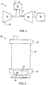
- Fig. 1 shows a schematic view of gas turbine engine 10 as may be used herein.
- the gas turbine engine 10 may include a compressor 15.
- the compressor 15 compresses an incoming flow of air 20.
- the compressor 15 delivers the compressed flow of air 20 to a combustor 25.
- the combustor 25 mixes the compressed flow of air 20 with a pressurized flow of fuel 30 and ignites the mixture to create a flow of combustion gases 35.
- the gas turbine engine 10 may include any number of combustors 25.
- the flow of combustion gases 35 is in turn delivered to a turbine 40.
- the flow of combustion gases 35 drives the turbine 40 so as to produce mechanical work.
- the mechanical work produced in the turbine 40 drives the compressor 15 via a shaft 45 and an external load 50 such as an electrical generator and the like.
- the gas turbine engine 10 may use natural gas, various types of syngas, and/or other types of fuels.
- the gas turbine engine 10 may be any one of a number of different gas turbine engines offered by General Electric Company of Schenectady, New York, including, but not limited to, those such as a 7 or a 9 series heavy duty gas turbine engine and the like.
- the gas turbine engine 10 may have different configurations and may use other types of components.
- Other types of gas turbine engines also may be used herein.
- Multiple gas turbine engines, other types of turbines, and other types of power generation equipment also may be used herein together.
- Fig. 2 is an example of a nozzle 55 that may be used with the turbine 40 described above.
- the nozzle 55 may include a nozzle vane 60 that extends between an inner platform 65 and an outer platform 70.
- a number of the nozzles 55 may be combined into a circumferential array to form a stage with a number of rotor blades (not shown).
- the nozzle 55 also may include an impingement cooling assembly 85 with an impingement plenum 90.
- the impingement plenum 90 may have a number of impingement apertures 95 formed therein.
- the impingement plenum 90 may be in communication with the flow of air 20 from the compressor 15 or another source via a spoolie or other type of cooling conduit. The flow of air 20 extends through the nozzle vane 60, into the impingement cooling assembly 85, and out via the impingement apertures 95 so as to impingement cool a portion of the nozzle 55 or elsewhere.
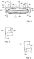
- Fig. 3 shows portions of an example of a nozzle 100 as may be described herein.
- the nozzle 100 includes a vane 110 extending from platform 120.
- the platform 120 may include a platform cavity 140.
- the vane 110 may include an airflow cavity 150 therein.
- the airflow cavity 150 may be in communication with the platform cavity 140 so as to provide the flow of air 20 from the compressor 15 or elsewhere.
- the nozzle 100 also may include an impingement cooling assembly 160.
- the impingement cooling assembly 160 may include an impingement plenum 170.
- the impingement plenum 170 may include a spoolie or other type of cooling conduit 180 in communication with the flow of air 20 from the airflow cavity 150.
- Other components and other configurations also may be used herein.
- the impingement plenum 170 may be positioned and retained within the platform cavity 140.
- the impingement plenum 170 may be retained within the platform cavity 140 on one side via a retention plate 190.
- the retention plate 190 may be a substantially flat plate and the like.
- the retention plate 190 may be in the form of a seal carrier 200 as is shown.
- the seal carrier 200 may have a number of seals 210 thereon.
- the retention plate 190 and the seal carrier 200 may have any size, shape, or configuration.
- the retention plate 190 also may take the form of a number of welded tabs, a welded ring, and the like. Any type of mechanical retention features may be used herein.
- the retention plate 190, the seal carrier 200, and the like may be retained within the platform cavity 140 via one or more platform hooks 220 and/or plate hooks 230.
- the retention plate 190 may be positioned on a first side 235 of the impingement plenum 170.
- the platform hooks 220 and the plate hooks 230 may take any configuration of male and female members in any orientation.
- One or more of the hooks 220, 230 may be angled so as to allow for tool clearances for machining and the like.
- either of the hooks 220, 230 also may take a largely cylindrical or elliptical protrusion or contour 280.
- one or more pins 290 are used as a retention feature.
- the hooks 220, 230, the cylindrical contour 280, the pins 290, and other structures may be used in any combination to retain the retention plate 190 within the platform cavity 140, i.e., combinations of hooks 220, 230 and pins 290 may be used together in any orientation.
- the impingement cooling assembly 160 also may use a compliant seal gasket 240 about a second side 245 of the impingement plenum 170 and the platform cavity 140.
- the compliant seal gasket 240 may extend around the perimeter of the impingement plenum 170.
- a retention shelf 250 also may be used adjacent to the compliant seal gasket 240.
- the impingement plenum 170 thus largely floats about the compliant seal gasket 240. Given such, the use of welding and the like may be avoided herein.
- Other types of seals also may be used herein about the second side 245 of the impingement plenum 170.
- One or more seals 260 also may be positioned about the slash face 270 of the platform 120.
- the seals 260 may be in the form of a number of spline seals and the like. Other types of seals may be used herein.
- a number of the seals 260 may be retained by the retention plate 190, the seal carrier 200, or other structures so as to allow tight radial packing.
- the seals 260 may form a plenum that is pressurized with a post-impingement flow routed from the platform cavity 140. Other components and other configurations may be used herein.
- the nozzle 100 described herein thus may maintain the impingement cooling assembly 160 nested therein between the mechanical retention of the retention plate 190 on one side and the compliant seal gasket 240 on the other.
- the impingement cooling assembly 160 thus provides effective cooling about the nozzle 100 without the use of welding or complex sidewall cores in a minimal radial space. Non-weldable materials thus may be used herein.
- the impingement cooling assembly 160 permits the nozzle 100 to face the high gas path temperatures while meeting lifetime and maintenance requirements in a producible design. Retaining the impingement cooling assembly 160 with the seal carrier 200 also permits a minimal radial envelope.
Description
- The present application relates generally to gas turbine engines and more particularly relate to a cooling assembly for an inner platform of a cantilevered turbine nozzle and the like.
- Impingement cooling systems have been used with turbine machinery to cool various types of components such as casings, buckets, nozzles, and the like. Impingement cooling systems cool the components via an airflow so as to maintain adequate clearances between the components and to promote adequate component lifetime. One issue with some types of known impingement cooling systems, however, is that they tend to require complicated castings and/or structural welding. Such structures may have low durability or may be expensive to produce and repair.
-
WO 02/092970 EP 0940562 describes a gas turbine having a cooling structure disposed on an outside peripheral side of a movable vane and a sealing structure disposed on the inside peripheral side thereof in which leakage of sealing air is suppressed to prevent invasion of combustion gas into turbine disc and enlargement of sealing air clearance is prevented.EP 0911486 describes a gas turbine stationary blade in which an entire cooling effect of the inner shroud is further enhanced by a configuration provided such that the amount of cooling air entering a leading edge portion and flow velocity thereof are increased with cooling effect thereof being further enhanced by agitation of the cooling air and also cooling air flowing in both side edge portions is increased. - There is thus a desire for a producible cooling assembly for use with turbine nozzles. Preferably, such a producible cooling assembly can adequately face high gas path temperatures while meeting lifetime and maintenance requirements as well as being reasonable in cost.
- The present application provides an inner platform for a gas turbine nozzle vane and a gas turbine nozzle vane as defined in the appended claims.
- Various features and improvements of the present invention will become apparent to one of ordinary skill in the art upon review of the following detailed description when taken in conjunction with the several drawings and the appended claims. In the drawings:
-
Fig. 1 is a schematic diagram of a gas turbine engine showing a compressor, combustor, and a turbine. -
Fig. 2 is a partial side view of a nozzle vane with an impingement cooling assembly therein. -
Fig. 3 is a partial side view of an example of a nozzle vane with an impingement cooling assembly as may be described herein. -
Fig. 4 is a partial side view of an example of a retention plate positioned within a platform cavity. -
Fig. 5 is a partial side view of a further example of a retention plate positioned within a platform cavity. - Referring now to the drawings, in which like numerals refer to like elements throughout the several views,
Fig. 1 shows a schematic view ofgas turbine engine 10 as may be used herein. Thegas turbine engine 10 may include acompressor 15. Thecompressor 15 compresses an incoming flow ofair 20. Thecompressor 15 delivers the compressed flow ofair 20 to acombustor 25. Thecombustor 25 mixes the compressed flow ofair 20 with a pressurized flow offuel 30 and ignites the mixture to create a flow ofcombustion gases 35. Although only asingle combustor 25 is shown, thegas turbine engine 10 may include any number ofcombustors 25. The flow ofcombustion gases 35 is in turn delivered to aturbine 40. The flow ofcombustion gases 35 drives theturbine 40 so as to produce mechanical work. The mechanical work produced in theturbine 40 drives thecompressor 15 via ashaft 45 and anexternal load 50 such as an electrical generator and the like. - The
gas turbine engine 10 may use natural gas, various types of syngas, and/or other types of fuels. Thegas turbine engine 10 may be any one of a number of different gas turbine engines offered by General Electric Company of Schenectady, New York, including, but not limited to, those such as a 7 or a 9 series heavy duty gas turbine engine and the like. Thegas turbine engine 10 may have different configurations and may use other types of components. Other types of gas turbine engines also may be used herein. Multiple gas turbine engines, other types of turbines, and other types of power generation equipment also may be used herein together. -
Fig. 2 is an example of anozzle 55 that may be used with theturbine 40 described above. Generally described, thenozzle 55 may include anozzle vane 60 that extends between aninner platform 65 and anouter platform 70. A number of thenozzles 55 may be combined into a circumferential array to form a stage with a number of rotor blades (not shown). - The
nozzle 55 also may include animpingement cooling assembly 85 with animpingement plenum 90. Theimpingement plenum 90 may have a number ofimpingement apertures 95 formed therein. Theimpingement plenum 90 may be in communication with the flow ofair 20 from thecompressor 15 or another source via a spoolie or other type of cooling conduit. The flow ofair 20 extends through thenozzle vane 60, into theimpingement cooling assembly 85, and out via theimpingement apertures 95 so as to impingement cool a portion of thenozzle 55 or elsewhere. -
Fig. 3 shows portions of an example of anozzle 100 as may be described herein. In addition to other components, thenozzle 100 includes avane 110 extending fromplatform 120. Theplatform 120 may include aplatform cavity 140. Thevane 110 may include anairflow cavity 150 therein. Theairflow cavity 150 may be in communication with theplatform cavity 140 so as to provide the flow ofair 20 from thecompressor 15 or elsewhere. Thenozzle 100 also may include animpingement cooling assembly 160. Theimpingement cooling assembly 160 may include animpingement plenum 170. Theimpingement plenum 170 may include a spoolie or other type ofcooling conduit 180 in communication with the flow ofair 20 from theairflow cavity 150. Other components and other configurations also may be used herein. - The
impingement plenum 170 may be positioned and retained within theplatform cavity 140. Theimpingement plenum 170 may be retained within theplatform cavity 140 on one side via aretention plate 190. Theretention plate 190 may be a substantially flat plate and the like. Alternatively, theretention plate 190 may be in the form of aseal carrier 200 as is shown. Theseal carrier 200 may have a number ofseals 210 thereon. Theretention plate 190 and theseal carrier 200 may have any size, shape, or configuration. Theretention plate 190 also may take the form of a number of welded tabs, a welded ring, and the like. Any type of mechanical retention features may be used herein. - The
retention plate 190, theseal carrier 200, and the like may be retained within theplatform cavity 140 via one ormore platform hooks 220 and/orplate hooks 230. Theretention plate 190 may be positioned on afirst side 235 of theimpingement plenum 170. Theplatform hooks 220 and theplate hooks 230 may take any configuration of male and female members in any orientation. One or more of thehooks Fig. 4 , either of thehooks contour 280. Furthermore as is shown inFig. 5 , one ormore pins 290 are used as a retention feature. Thehooks cylindrical contour 280, thepins 290, and other structures may be used in any combination to retain theretention plate 190 within theplatform cavity 140, i.e., combinations ofhooks pins 290 may be used together in any orientation. - Referring again to
Fig. 3 , theimpingement cooling assembly 160 also may use acompliant seal gasket 240 about asecond side 245 of theimpingement plenum 170 and theplatform cavity 140. Thecompliant seal gasket 240 may extend around the perimeter of theimpingement plenum 170. Aretention shelf 250 also may be used adjacent to thecompliant seal gasket 240. Theimpingement plenum 170 thus largely floats about thecompliant seal gasket 240. Given such, the use of welding and the like may be avoided herein. Other types of seals also may be used herein about thesecond side 245 of theimpingement plenum 170. - One or
more seals 260 also may be positioned about theslash face 270 of theplatform 120. Theseals 260 may be in the form of a number of spline seals and the like. Other types of seals may be used herein. A number of theseals 260 may be retained by theretention plate 190, theseal carrier 200, or other structures so as to allow tight radial packing. Theseals 260 may form a plenum that is pressurized with a post-impingement flow routed from theplatform cavity 140. Other components and other configurations may be used herein. - The
nozzle 100 described herein thus may maintain theimpingement cooling assembly 160 nested therein between the mechanical retention of theretention plate 190 on one side and thecompliant seal gasket 240 on the other. Theimpingement cooling assembly 160 thus provides effective cooling about thenozzle 100 without the use of welding or complex sidewall cores in a minimal radial space. Non-weldable materials thus may be used herein. Theimpingement cooling assembly 160 permits thenozzle 100 to face the high gas path temperatures while meeting lifetime and maintenance requirements in a producible design. Retaining theimpingement cooling assembly 160 with theseal carrier 200 also permits a minimal radial envelope. - It should be apparent that the foregoing relates only to certain embodiments of the present invention. Numerous changes and modifications may be made herein by one of ordinary skill in the art without departing from the scope of the invention as defined by the following claims and the equivalents thereof.
Claims (10)
- An inner platform (65) of a gas turbine (40) nozzle vane (55), comprising:a platform cavity (140);an impingement plenum (170) positioned within the platform cavity (140);a retention plate (190) positioned on a first side (235) of the impingement plenum (170); anda compliant seal (240) positioned on a second side (245) of the impingement plenum (170);characterized by one or more pins (290) extending into the platform cavity (140) such that the retention plate (190) is retained in the platform cavity (140).
- The inner platform of claim 1, wherein the retention plate (190) comprises a seal carrier (200).
- The inner platform of any preceding claim, wherein the platform cavity (140) comprises one or more platform hooks (220) and the retention plate (190) comprises one or more plate hooks (230).
- The inner platform of claim 3, wherein either of the platform hooks (220) or the plate hooks (230) comprise a cylindrical contour (280).
- The inner platform of any preceding claim, wherein the compliant seal (240) comprises a compliant seal gasket.
- The inner platform of any preceding claim, wherein the platform cavity (140) comprises a retention shelf (250) positioned about the compliant seal (240).
- The inner platform of any preceding claim, further comprising a slash face (270) and wherein the slash face (270) comprises a seal or a plurality of seals (260) thereon.
- The inner platform of any preceding claim, wherein the impingement plenum (170) comprises a cooling conduit (180) in communication with a flow of air (20).
- The inner platform of any preceding claim, wherein the impingement plenum (170) comprises a plurality of apertures (95) positioned about a nozzle platform.
- A gas turbine nozzle vane (110) comprising the inner platform (120) of any preceding claim.
Applications Claiming Priority (1)
| Application Number | Priority Date | Filing Date | Title |
|---|---|---|---|
| US13/345,776 US8944751B2 (en) | 2012-01-09 | 2012-01-09 | Turbine nozzle cooling assembly |
Publications (2)
| Publication Number | Publication Date |
|---|---|
| EP2613012A1 EP2613012A1 (en) | 2013-07-10 |
| EP2613012B1 true EP2613012B1 (en) | 2017-08-23 |
Family
ID=47665882
Family Applications (1)
| Application Number | Title | Priority Date | Filing Date |
|---|---|---|---|
| EP13150161.1A Active EP2613012B1 (en) | 2012-01-09 | 2013-01-03 | Turbine nozzle cooling assembly |
Country Status (5)
| Country | Link |
|---|---|
| US (1) | US8944751B2 (en) |
| EP (1) | EP2613012B1 (en) |
| JP (1) | JP5998045B2 (en) |
| CN (1) | CN103233784B (en) |
| RU (1) | RU2614892C2 (en) |
Families Citing this family (4)
| Publication number | Priority date | Publication date | Assignee | Title |
|---|---|---|---|---|
| US9562439B2 (en) | 2013-12-27 | 2017-02-07 | General Electric Company | Turbine nozzle and method for cooling a turbine nozzle of a gas turbine engine |
| US10260356B2 (en) | 2016-06-02 | 2019-04-16 | General Electric Company | Nozzle cooling system for a gas turbine engine |
| US11466700B2 (en) * | 2017-02-28 | 2022-10-11 | Unison Industries, Llc | Fan casing and mount bracket for oil cooler |
| US10436041B2 (en) * | 2017-04-07 | 2019-10-08 | General Electric Company | Shroud assembly for turbine systems |
Family Cites Families (53)
| Publication number | Priority date | Publication date | Assignee | Title |
|---|---|---|---|---|
| US4187054A (en) | 1978-04-20 | 1980-02-05 | General Electric Company | Turbine band cooling system |
| JPS58148202A (en) * | 1982-02-26 | 1983-09-03 | Hitachi Ltd | Nozzle segment of gas turbine |
| US4505640A (en) * | 1983-12-13 | 1985-03-19 | United Technologies Corporation | Seal means for a blade attachment slot of a rotor assembly |
| US5197852A (en) | 1990-05-31 | 1993-03-30 | General Electric Company | Nozzle band overhang cooling |
| JPH0552102A (en) * | 1991-08-23 | 1993-03-02 | Toshiba Corp | Gas turbine |
| EP0791127B1 (en) | 1994-11-10 | 2000-03-08 | Siemens Westinghouse Power Corporation | Gas turbine vane with a cooled inner shroud |
| US6383602B1 (en) | 1996-12-23 | 2002-05-07 | General Electric Company | Method for improving the cooling effectiveness of a gaseous coolant stream which flows through a substrate, and related articles of manufacture |
| US5746573A (en) * | 1996-12-31 | 1998-05-05 | Westinghouse Electric Corporation | Vane segment compliant seal assembly |
| JP3495579B2 (en) | 1997-10-28 | 2004-02-09 | 三菱重工業株式会社 | Gas turbine stationary blade |
| FR2771446B1 (en) * | 1997-11-27 | 1999-12-31 | Snecma | COOLING TURBINE DISTRIBUTOR BLADE |
| US6146091A (en) | 1998-03-03 | 2000-11-14 | Mitsubishi Heavy Industries, Ltd. | Gas turbine cooling structure |
| US6065928A (en) * | 1998-07-22 | 2000-05-23 | General Electric Company | Turbine nozzle having purge air circuit |
| US6227798B1 (en) | 1999-11-30 | 2001-05-08 | General Electric Company | Turbine nozzle segment band cooling |
| US6386825B1 (en) | 2000-04-11 | 2002-05-14 | General Electric Company | Apparatus and methods for impingement cooling of a side wall of a turbine nozzle segment |
| US6419445B1 (en) | 2000-04-11 | 2002-07-16 | General Electric Company | Apparatus for impingement cooling a side wall adjacent an undercut region of a turbine nozzle segment |
| US6418618B1 (en) | 2000-04-11 | 2002-07-16 | General Electric Company | Method of controlling the side wall thickness of a turbine nozzle segment for improved cooling |
| US6382906B1 (en) | 2000-06-16 | 2002-05-07 | General Electric Company | Floating spoolie cup impingement baffle |
| US6398488B1 (en) * | 2000-09-13 | 2002-06-04 | General Electric Company | Interstage seal cooling |
| US6508620B2 (en) * | 2001-05-17 | 2003-01-21 | Pratt & Whitney Canada Corp. | Inner platform impingement cooling by supply air from outside |
| US6530744B2 (en) | 2001-05-29 | 2003-03-11 | General Electric Company | Integral nozzle and shroud |
| US6503051B2 (en) | 2001-06-06 | 2003-01-07 | General Electric Company | Overlapping interference seal and methods for forming the seal |
| US6652220B2 (en) | 2001-11-15 | 2003-11-25 | General Electric Company | Methods and apparatus for cooling gas turbine nozzles |
| US6769865B2 (en) | 2002-03-22 | 2004-08-03 | General Electric Company | Band cooled turbine nozzle |
| US6761529B2 (en) | 2002-07-25 | 2004-07-13 | Mitshubishi Heavy Industries, Ltd. | Cooling structure of stationary blade, and gas turbine |
| US6932568B2 (en) | 2003-02-27 | 2005-08-23 | General Electric Company | Turbine nozzle segment cantilevered mount |
| US6984101B2 (en) | 2003-07-14 | 2006-01-10 | Siemens Westinghouse Power Corporation | Turbine vane plate assembly |
| FR2858829B1 (en) * | 2003-08-12 | 2008-03-14 | Snecma Moteurs | AUBE COOLING OF GAS TURBINE ENGINE |
| US7147440B2 (en) * | 2003-10-31 | 2006-12-12 | General Electric Company | Methods and apparatus for cooling gas turbine engine rotor assemblies |
| US6887033B1 (en) * | 2003-11-10 | 2005-05-03 | General Electric Company | Cooling system for nozzle segment platform edges |
| US7029228B2 (en) | 2003-12-04 | 2006-04-18 | General Electric Company | Method and apparatus for convective cooling of side-walls of turbine nozzle segments |
| US7086829B2 (en) * | 2004-02-03 | 2006-08-08 | General Electric Company | Film cooling for the trailing edge of a steam cooled nozzle |
| US7094026B2 (en) | 2004-04-29 | 2006-08-22 | General Electric Company | System for sealing an inner retainer segment and support ring in a gas turbine and methods therefor |
| US7252481B2 (en) | 2004-05-14 | 2007-08-07 | Pratt & Whitney Canada Corp. | Natural frequency tuning of gas turbine engine blades |
| FR2872541B1 (en) * | 2004-06-30 | 2006-11-10 | Snecma Moteurs Sa | FIXED WATER TURBINE WITH IMPROVED COOLING |
| US7007488B2 (en) * | 2004-07-06 | 2006-03-07 | General Electric Company | Modulated flow turbine nozzle |
| JP4412081B2 (en) * | 2004-07-07 | 2010-02-10 | 株式会社日立製作所 | Gas turbine and gas turbine cooling method |
| US7219498B2 (en) | 2004-09-10 | 2007-05-22 | Honeywell International, Inc. | Waffled impingement effusion method |
| US7160078B2 (en) | 2004-09-23 | 2007-01-09 | General Electric Company | Mechanical solution for rail retention of turbine nozzles |
| US7140835B2 (en) | 2004-10-01 | 2006-11-28 | General Electric Company | Corner cooled turbine nozzle |
| US7338253B2 (en) | 2005-09-15 | 2008-03-04 | General Electric Company | Resilient seal on trailing edge of turbine inner shroud and method for shroud post impingement cavity sealing |
| US7575416B2 (en) * | 2006-05-18 | 2009-08-18 | United Technologies Corporation | Rotor assembly for a rotary machine |
| US7669422B2 (en) | 2006-07-26 | 2010-03-02 | General Electric Company | Combustor liner and method of fabricating same |
| US7900433B2 (en) | 2006-08-31 | 2011-03-08 | United Technologies Corporation | Fan exhaust nozzle for turbofan engine |
| US8801370B2 (en) | 2006-10-12 | 2014-08-12 | General Electric Company | Turbine case impingement cooling for heavy duty gas turbines |
| US7798775B2 (en) | 2006-12-21 | 2010-09-21 | General Electric Company | Cantilevered nozzle with crowned flange to improve outer band low cycle fatigue |
| US20110189000A1 (en) | 2007-05-01 | 2011-08-04 | General Electric Company | System for regulating a cooling fluid within a turbomachine |
| GB2452515B (en) * | 2007-09-06 | 2009-08-05 | Siemens Ag | Seal coating between rotor blade and rotor disk slot in gas turbine engine |
| US7946801B2 (en) | 2007-12-27 | 2011-05-24 | General Electric Company | Multi-source gas turbine cooling |
| US8118548B2 (en) | 2008-09-15 | 2012-02-21 | General Electric Company | Shroud for a turbomachine |
| US8142138B2 (en) | 2009-05-01 | 2012-03-27 | General Electric Company | Turbine engine having cooling pin |
| US20100284800A1 (en) | 2009-05-11 | 2010-11-11 | General Electric Company | Turbine nozzle with sidewall cooling plenum |
| ES2561037T3 (en) | 2009-07-03 | 2016-02-24 | Alstom Technology Ltd | Method of replacing a cover of a guide blade of a gas turbine |
| US8740551B2 (en) | 2009-08-18 | 2014-06-03 | Pratt & Whitney Canada Corp. | Blade outer air seal cooling |
-
2012
- 2012-01-09 US US13/345,776 patent/US8944751B2/en active Active
- 2012-12-27 JP JP2012283890A patent/JP5998045B2/en active Active
- 2012-12-27 RU RU2012158314A patent/RU2614892C2/en active
-
2013
- 2013-01-03 EP EP13150161.1A patent/EP2613012B1/en active Active
- 2013-01-09 CN CN201310007262.6A patent/CN103233784B/en active Active
Non-Patent Citations (1)
| Title |
|---|
| None * |
Also Published As
| Publication number | Publication date |
|---|---|
| JP5998045B2 (en) | 2016-09-28 |
| CN103233784A (en) | 2013-08-07 |
| US20130175357A1 (en) | 2013-07-11 |
| RU2012158314A (en) | 2014-07-10 |
| RU2614892C2 (en) | 2017-03-30 |
| US8944751B2 (en) | 2015-02-03 |
| CN103233784B (en) | 2016-03-16 |
| JP2013142395A (en) | 2013-07-22 |
| EP2613012A1 (en) | 2013-07-10 |
Similar Documents
| Publication | Publication Date | Title |
|---|---|---|
| EP2612995B1 (en) | Turbine nozzle compartmentalized cooling system | |
| US9151174B2 (en) | Sealing assembly for use in a rotary machine and methods for assembling a rotary machine | |
| EP2612991B1 (en) | Turbine nozzle with a flow groove | |
| US20120003091A1 (en) | Rotor assembly for use in gas turbine engines and method for assembling the same | |
| US9963989B2 (en) | Gas turbine engine vane-to-transition duct seal | |
| EP2613013B1 (en) | Stage and turbine of a gas turbine engine | |
| EP2613012B1 (en) | Turbine nozzle cooling assembly | |
| EP2613004B1 (en) | Turbine nozzle assembly methods | |
| EP2615253B1 (en) | Turbine vane seal carrier with slots for cooling and assembly | |
| EP2562359A2 (en) | Turbine nozzle vane retention system | |
| EP2971545A1 (en) | Low pressure loss cooled blade | |
| US10822976B2 (en) | Nozzle insert rib cap | |
| EP2716876A1 (en) | Solid seal with cooling pathways | |
| US9745920B2 (en) | Gas turbine nozzles with embossments in airfoil cavities | |
| US20140271109A1 (en) | Axial compressor and method for controlling stage-to-stage leakage therein | |
| CN107461225B (en) | Nozzle cooling system for gas turbine engine | |
| EP2503100A2 (en) | Turbine blade, corresponding assembly and manufacturing method | |
| US20150075180A1 (en) | Systems and methods for providing one or more cooling holes in a slash face of a turbine bucket | |
| EP2617948A2 (en) | Near flow path seal for a turbomachine | |
| EP2672065A2 (en) | Shroud for a turbine, corresponding turbine and method of assembling the same | |
| US20140356155A1 (en) | Nozzle Insert Rib Cap | |
| WO2014022511A1 (en) | Turbine shroud for a turbomachine |
Legal Events
| Date | Code | Title | Description |
|---|---|---|---|
| PUAI | Public reference made under article 153(3) epc to a published international application that has entered the european phase |
Free format text: ORIGINAL CODE: 0009012 |
|
| AK | Designated contracting states |
Kind code of ref document: A1 Designated state(s): AL AT BE BG CH CY CZ DE DK EE ES FI FR GB GR HR HU IE IS IT LI LT LU LV MC MK MT NL NO PL PT RO RS SE SI SK SM TR |
|
| AX | Request for extension of the european patent |
Extension state: BA ME |
|
| 17P | Request for examination filed |
Effective date: 20140110 |
|
| RBV | Designated contracting states (corrected) |
Designated state(s): AL AT BE BG CH CY CZ DE DK EE ES FI FR GB GR HR HU IE IS IT LI LT LU LV MC MK MT NL NO PL PT RO RS SE SI SK SM TR |
|
| GRAP | Despatch of communication of intention to grant a patent |
Free format text: ORIGINAL CODE: EPIDOSNIGR1 |
|
| RIC1 | Information provided on ipc code assigned before grant |
Ipc: F01D 11/00 20060101AFI20170307BHEP |
|
| INTG | Intention to grant announced |
Effective date: 20170407 |
|
| GRAS | Grant fee paid |
Free format text: ORIGINAL CODE: EPIDOSNIGR3 |
|
| GRAA | (expected) grant |
Free format text: ORIGINAL CODE: 0009210 |
|
| AK | Designated contracting states |
Kind code of ref document: B1 Designated state(s): AL AT BE BG CH CY CZ DE DK EE ES FI FR GB GR HR HU IE IS IT LI LT LU LV MC MK MT NL NO PL PT RO RS SE SI SK SM TR |
|
| REG | Reference to a national code |
Ref country code: GB Ref legal event code: FG4D |
|
| REG | Reference to a national code |
Ref country code: CH Ref legal event code: EP |
|
| REG | Reference to a national code |
Ref country code: AT Ref legal event code: REF Ref document number: 921576 Country of ref document: AT Kind code of ref document: T Effective date: 20170915 |
|
| REG | Reference to a national code |
Ref country code: IE Ref legal event code: FG4D |
|
| REG | Reference to a national code |
Ref country code: DE Ref legal event code: R096 Ref document number: 602013025324 Country of ref document: DE |
|
| REG | Reference to a national code |
Ref country code: NL Ref legal event code: MP Effective date: 20170823 |
|
| REG | Reference to a national code |
Ref country code: LT Ref legal event code: MG4D |
|
| REG | Reference to a national code |
Ref country code: AT Ref legal event code: MK05 Ref document number: 921576 Country of ref document: AT Kind code of ref document: T Effective date: 20170823 |
|
| PG25 | Lapsed in a contracting state [announced via postgrant information from national office to epo] |
Ref country code: NL Free format text: LAPSE BECAUSE OF FAILURE TO SUBMIT A TRANSLATION OF THE DESCRIPTION OR TO PAY THE FEE WITHIN THE PRESCRIBED TIME-LIMIT Effective date: 20170823 Ref country code: NO Free format text: LAPSE BECAUSE OF FAILURE TO SUBMIT A TRANSLATION OF THE DESCRIPTION OR TO PAY THE FEE WITHIN THE PRESCRIBED TIME-LIMIT Effective date: 20171123 Ref country code: FI Free format text: LAPSE BECAUSE OF FAILURE TO SUBMIT A TRANSLATION OF THE DESCRIPTION OR TO PAY THE FEE WITHIN THE PRESCRIBED TIME-LIMIT Effective date: 20170823 Ref country code: SE Free format text: LAPSE BECAUSE OF FAILURE TO SUBMIT A TRANSLATION OF THE DESCRIPTION OR TO PAY THE FEE WITHIN THE PRESCRIBED TIME-LIMIT Effective date: 20170823 Ref country code: HR Free format text: LAPSE BECAUSE OF FAILURE TO SUBMIT A TRANSLATION OF THE DESCRIPTION OR TO PAY THE FEE WITHIN THE PRESCRIBED TIME-LIMIT Effective date: 20170823 Ref country code: LT Free format text: LAPSE BECAUSE OF FAILURE TO SUBMIT A TRANSLATION OF THE DESCRIPTION OR TO PAY THE FEE WITHIN THE PRESCRIBED TIME-LIMIT Effective date: 20170823 Ref country code: AT Free format text: LAPSE BECAUSE OF FAILURE TO SUBMIT A TRANSLATION OF THE DESCRIPTION OR TO PAY THE FEE WITHIN THE PRESCRIBED TIME-LIMIT Effective date: 20170823 |
|
| PG25 | Lapsed in a contracting state [announced via postgrant information from national office to epo] |
Ref country code: ES Free format text: LAPSE BECAUSE OF FAILURE TO SUBMIT A TRANSLATION OF THE DESCRIPTION OR TO PAY THE FEE WITHIN THE PRESCRIBED TIME-LIMIT Effective date: 20170823 Ref country code: IS Free format text: LAPSE BECAUSE OF FAILURE TO SUBMIT A TRANSLATION OF THE DESCRIPTION OR TO PAY THE FEE WITHIN THE PRESCRIBED TIME-LIMIT Effective date: 20171223 Ref country code: GR Free format text: LAPSE BECAUSE OF FAILURE TO SUBMIT A TRANSLATION OF THE DESCRIPTION OR TO PAY THE FEE WITHIN THE PRESCRIBED TIME-LIMIT Effective date: 20171124 Ref country code: PL Free format text: LAPSE BECAUSE OF FAILURE TO SUBMIT A TRANSLATION OF THE DESCRIPTION OR TO PAY THE FEE WITHIN THE PRESCRIBED TIME-LIMIT Effective date: 20170823 Ref country code: BG Free format text: LAPSE BECAUSE OF FAILURE TO SUBMIT A TRANSLATION OF THE DESCRIPTION OR TO PAY THE FEE WITHIN THE PRESCRIBED TIME-LIMIT Effective date: 20171123 Ref country code: LV Free format text: LAPSE BECAUSE OF FAILURE TO SUBMIT A TRANSLATION OF THE DESCRIPTION OR TO PAY THE FEE WITHIN THE PRESCRIBED TIME-LIMIT Effective date: 20170823 Ref country code: RS Free format text: LAPSE BECAUSE OF FAILURE TO SUBMIT A TRANSLATION OF THE DESCRIPTION OR TO PAY THE FEE WITHIN THE PRESCRIBED TIME-LIMIT Effective date: 20170823 |
|
| PG25 | Lapsed in a contracting state [announced via postgrant information from national office to epo] |
Ref country code: CZ Free format text: LAPSE BECAUSE OF FAILURE TO SUBMIT A TRANSLATION OF THE DESCRIPTION OR TO PAY THE FEE WITHIN THE PRESCRIBED TIME-LIMIT Effective date: 20170823 Ref country code: DK Free format text: LAPSE BECAUSE OF FAILURE TO SUBMIT A TRANSLATION OF THE DESCRIPTION OR TO PAY THE FEE WITHIN THE PRESCRIBED TIME-LIMIT Effective date: 20170823 Ref country code: RO Free format text: LAPSE BECAUSE OF FAILURE TO SUBMIT A TRANSLATION OF THE DESCRIPTION OR TO PAY THE FEE WITHIN THE PRESCRIBED TIME-LIMIT Effective date: 20170823 |
|
| REG | Reference to a national code |
Ref country code: DE Ref legal event code: R097 Ref document number: 602013025324 Country of ref document: DE |
|
| PG25 | Lapsed in a contracting state [announced via postgrant information from national office to epo] |
Ref country code: SM Free format text: LAPSE BECAUSE OF FAILURE TO SUBMIT A TRANSLATION OF THE DESCRIPTION OR TO PAY THE FEE WITHIN THE PRESCRIBED TIME-LIMIT Effective date: 20170823 Ref country code: SK Free format text: LAPSE BECAUSE OF FAILURE TO SUBMIT A TRANSLATION OF THE DESCRIPTION OR TO PAY THE FEE WITHIN THE PRESCRIBED TIME-LIMIT Effective date: 20170823 Ref country code: EE Free format text: LAPSE BECAUSE OF FAILURE TO SUBMIT A TRANSLATION OF THE DESCRIPTION OR TO PAY THE FEE WITHIN THE PRESCRIBED TIME-LIMIT Effective date: 20170823 |
|
| PLBE | No opposition filed within time limit |
Free format text: ORIGINAL CODE: 0009261 |
|
| STAA | Information on the status of an ep patent application or granted ep patent |
Free format text: STATUS: NO OPPOSITION FILED WITHIN TIME LIMIT |
|
| 26N | No opposition filed |
Effective date: 20180524 |
|
| PG25 | Lapsed in a contracting state [announced via postgrant information from national office to epo] |
Ref country code: SI Free format text: LAPSE BECAUSE OF FAILURE TO SUBMIT A TRANSLATION OF THE DESCRIPTION OR TO PAY THE FEE WITHIN THE PRESCRIBED TIME-LIMIT Effective date: 20170823 |
|
| REG | Reference to a national code |
Ref country code: CH Ref legal event code: PL |
|
| PG25 | Lapsed in a contracting state [announced via postgrant information from national office to epo] |
Ref country code: FR Free format text: LAPSE BECAUSE OF NON-PAYMENT OF DUE FEES Effective date: 20180131 Ref country code: LU Free format text: LAPSE BECAUSE OF NON-PAYMENT OF DUE FEES Effective date: 20180103 |
|
| REG | Reference to a national code |
Ref country code: IE Ref legal event code: MM4A |
|
| REG | Reference to a national code |
Ref country code: FR Ref legal event code: ST Effective date: 20180928 |
|
| REG | Reference to a national code |
Ref country code: BE Ref legal event code: MM Effective date: 20180131 |
|
| PG25 | Lapsed in a contracting state [announced via postgrant information from national office to epo] |
Ref country code: LI Free format text: LAPSE BECAUSE OF NON-PAYMENT OF DUE FEES Effective date: 20180131 Ref country code: CH Free format text: LAPSE BECAUSE OF NON-PAYMENT OF DUE FEES Effective date: 20180131 Ref country code: BE Free format text: LAPSE BECAUSE OF NON-PAYMENT OF DUE FEES Effective date: 20180131 |
|
| PG25 | Lapsed in a contracting state [announced via postgrant information from national office to epo] |
Ref country code: IE Free format text: LAPSE BECAUSE OF NON-PAYMENT OF DUE FEES Effective date: 20180103 |
|
| PG25 | Lapsed in a contracting state [announced via postgrant information from national office to epo] |
Ref country code: MC Free format text: LAPSE BECAUSE OF FAILURE TO SUBMIT A TRANSLATION OF THE DESCRIPTION OR TO PAY THE FEE WITHIN THE PRESCRIBED TIME-LIMIT Effective date: 20170823 |
|
| PG25 | Lapsed in a contracting state [announced via postgrant information from national office to epo] |
Ref country code: MT Free format text: LAPSE BECAUSE OF NON-PAYMENT OF DUE FEES Effective date: 20180103 |
|
| PG25 | Lapsed in a contracting state [announced via postgrant information from national office to epo] |
Ref country code: TR Free format text: LAPSE BECAUSE OF FAILURE TO SUBMIT A TRANSLATION OF THE DESCRIPTION OR TO PAY THE FEE WITHIN THE PRESCRIBED TIME-LIMIT Effective date: 20170823 |
|
| PG25 | Lapsed in a contracting state [announced via postgrant information from national office to epo] |
Ref country code: PT Free format text: LAPSE BECAUSE OF FAILURE TO SUBMIT A TRANSLATION OF THE DESCRIPTION OR TO PAY THE FEE WITHIN THE PRESCRIBED TIME-LIMIT Effective date: 20170823 Ref country code: HU Free format text: LAPSE BECAUSE OF FAILURE TO SUBMIT A TRANSLATION OF THE DESCRIPTION OR TO PAY THE FEE WITHIN THE PRESCRIBED TIME-LIMIT; INVALID AB INITIO Effective date: 20130103 |
|
| PG25 | Lapsed in a contracting state [announced via postgrant information from national office to epo] |
Ref country code: MK Free format text: LAPSE BECAUSE OF NON-PAYMENT OF DUE FEES Effective date: 20170823 Ref country code: CY Free format text: LAPSE BECAUSE OF FAILURE TO SUBMIT A TRANSLATION OF THE DESCRIPTION OR TO PAY THE FEE WITHIN THE PRESCRIBED TIME-LIMIT Effective date: 20170823 |
|
| PG25 | Lapsed in a contracting state [announced via postgrant information from national office to epo] |
Ref country code: AL Free format text: LAPSE BECAUSE OF FAILURE TO SUBMIT A TRANSLATION OF THE DESCRIPTION OR TO PAY THE FEE WITHIN THE PRESCRIBED TIME-LIMIT Effective date: 20170823 |
|
| PGFP | Annual fee paid to national office [announced via postgrant information from national office to epo] |
Ref country code: IT Payment date: 20230103 Year of fee payment: 11 Ref country code: DE Payment date: 20221220 Year of fee payment: 11 |
|
| P01 | Opt-out of the competence of the unified patent court (upc) registered |
Effective date: 20230522 |
|
| REG | Reference to a national code |
Ref country code: DE Ref legal event code: R081 Ref document number: 602013025324 Country of ref document: DE Owner name: GENERAL ELECTRIC TECHNOLOGY GMBH, CH Free format text: FORMER OWNER: GENERAL ELECTRIC COMPANY, SCHENECTADY, NY, US |
|
| PGFP | Annual fee paid to national office [announced via postgrant information from national office to epo] |
Ref country code: GB Payment date: 20231219 Year of fee payment: 12 |
|
| REG | Reference to a national code |
Ref country code: GB Ref legal event code: 732E Free format text: REGISTERED BETWEEN 20240222 AND 20240228 |