EP2613008A1 - Modification of turbine engine seal abradability - Google Patents
Modification of turbine engine seal abradability Download PDFInfo
- Publication number
- EP2613008A1 EP2613008A1 EP12198344.9A EP12198344A EP2613008A1 EP 2613008 A1 EP2613008 A1 EP 2613008A1 EP 12198344 A EP12198344 A EP 12198344A EP 2613008 A1 EP2613008 A1 EP 2613008A1
- Authority
- EP
- European Patent Office
- Prior art keywords
- seal
- abradability
- honeycomb
- substrate
- rotating
- Prior art date
- Legal status (The legal status is an assumption and is not a legal conclusion. Google has not performed a legal analysis and makes no representation as to the accuracy of the status listed.)
- Granted
Links
- 238000012986 modification Methods 0.000 title description 3
- 230000004048 modification Effects 0.000 title description 3
- 239000000758 substrate Substances 0.000 claims abstract description 34
- 239000000463 material Substances 0.000 claims abstract description 29
- 238000000034 method Methods 0.000 claims description 24
- 238000000576 coating method Methods 0.000 claims description 19
- 239000011248 coating agent Substances 0.000 claims description 17
- 238000010438 heat treatment Methods 0.000 claims description 5
- 230000002787 reinforcement Effects 0.000 claims description 5
- 238000004519 manufacturing process Methods 0.000 claims description 4
- 238000005468 ion implantation Methods 0.000 claims description 3
- 230000000873 masking effect Effects 0.000 claims description 3
- 238000005530 etching Methods 0.000 claims description 2
- 239000007789 gas Substances 0.000 description 14
- 238000005299 abrasion Methods 0.000 description 10
- 230000007246 mechanism Effects 0.000 description 10
- 230000008569 process Effects 0.000 description 10
- 238000009792 diffusion process Methods 0.000 description 8
- 239000000843 powder Substances 0.000 description 7
- 230000003068 static effect Effects 0.000 description 7
- PXHVJJICTQNCMI-UHFFFAOYSA-N Nickel Chemical compound [Ni] PXHVJJICTQNCMI-UHFFFAOYSA-N 0.000 description 6
- 238000005520 cutting process Methods 0.000 description 6
- 229910045601 alloy Inorganic materials 0.000 description 5
- 239000000956 alloy Substances 0.000 description 5
- 229910052782 aluminium Inorganic materials 0.000 description 5
- XAGFODPZIPBFFR-UHFFFAOYSA-N aluminium Chemical compound [Al] XAGFODPZIPBFFR-UHFFFAOYSA-N 0.000 description 5
- 238000007789 sealing Methods 0.000 description 5
- 238000005219 brazing Methods 0.000 description 4
- 230000001737 promoting effect Effects 0.000 description 4
- ZOXJGFHDIHLPTG-UHFFFAOYSA-N Boron Chemical compound [B] ZOXJGFHDIHLPTG-UHFFFAOYSA-N 0.000 description 3
- 230000008901 benefit Effects 0.000 description 3
- 230000015572 biosynthetic process Effects 0.000 description 3
- 229910052796 boron Inorganic materials 0.000 description 3
- 229910052759 nickel Inorganic materials 0.000 description 3
- 229910000601 superalloy Inorganic materials 0.000 description 3
- 229910000951 Aluminide Inorganic materials 0.000 description 2
- IJGRMHOSHXDMSA-UHFFFAOYSA-N Atomic nitrogen Chemical compound N#N IJGRMHOSHXDMSA-UHFFFAOYSA-N 0.000 description 2
- NPXOKRUENSOPAO-UHFFFAOYSA-N Raney nickel Chemical compound [Al].[Ni] NPXOKRUENSOPAO-UHFFFAOYSA-N 0.000 description 2
- OQPDWFJSZHWILH-UHFFFAOYSA-N [Al].[Al].[Al].[Ti] Chemical compound [Al].[Al].[Al].[Ti] OQPDWFJSZHWILH-UHFFFAOYSA-N 0.000 description 2
- 230000004323 axial length Effects 0.000 description 2
- 238000013461 design Methods 0.000 description 2
- 238000005304 joining Methods 0.000 description 2
- 229910052751 metal Inorganic materials 0.000 description 2
- 239000002184 metal Substances 0.000 description 2
- 229910000907 nickel aluminide Inorganic materials 0.000 description 2
- 239000012071 phase Substances 0.000 description 2
- 239000002344 surface layer Substances 0.000 description 2
- 229910021324 titanium aluminide Inorganic materials 0.000 description 2
- 238000011282 treatment Methods 0.000 description 2
- WVQBLGZPHOPPFO-UHFFFAOYSA-N 2-chloro-N-(2-ethyl-6-methylphenyl)-N-(1-methoxypropan-2-yl)acetamide Chemical compound CCC1=CC=CC(C)=C1N(C(C)COC)C(=O)CCl WVQBLGZPHOPPFO-UHFFFAOYSA-N 0.000 description 1
- UFHFLCQGNIYNRP-UHFFFAOYSA-N Hydrogen Chemical compound [H][H] UFHFLCQGNIYNRP-UHFFFAOYSA-N 0.000 description 1
- 239000012190 activator Substances 0.000 description 1
- AZDRQVAHHNSJOQ-UHFFFAOYSA-N alumane Chemical class [AlH3] AZDRQVAHHNSJOQ-UHFFFAOYSA-N 0.000 description 1
- 238000000137 annealing Methods 0.000 description 1
- 238000013459 approach Methods 0.000 description 1
- 230000006835 compression Effects 0.000 description 1
- 238000007906 compression Methods 0.000 description 1
- 238000010276 construction Methods 0.000 description 1
- 238000001816 cooling Methods 0.000 description 1
- 238000000280 densification Methods 0.000 description 1
- 230000000694 effects Effects 0.000 description 1
- 230000007613 environmental effect Effects 0.000 description 1
- 239000001257 hydrogen Substances 0.000 description 1
- 229910052739 hydrogen Inorganic materials 0.000 description 1
- 230000003993 interaction Effects 0.000 description 1
- 238000002844 melting Methods 0.000 description 1
- 230000008018 melting Effects 0.000 description 1
- 229910052757 nitrogen Inorganic materials 0.000 description 1
- 239000002245 particle Substances 0.000 description 1
- 230000002028 premature Effects 0.000 description 1
- 239000002002 slurry Substances 0.000 description 1
- 239000000126 substance Substances 0.000 description 1
- 238000012546 transfer Methods 0.000 description 1
- 230000007704 transition Effects 0.000 description 1
- 239000012808 vapor phase Substances 0.000 description 1
- 238000001947 vapour-phase growth Methods 0.000 description 1
- 238000003466 welding Methods 0.000 description 1
Images



Classifications
-
- F—MECHANICAL ENGINEERING; LIGHTING; HEATING; WEAPONS; BLASTING
- F01—MACHINES OR ENGINES IN GENERAL; ENGINE PLANTS IN GENERAL; STEAM ENGINES
- F01D—NON-POSITIVE DISPLACEMENT MACHINES OR ENGINES, e.g. STEAM TURBINES
- F01D11/00—Preventing or minimising internal leakage of working-fluid, e.g. between stages
- F01D11/001—Preventing or minimising internal leakage of working-fluid, e.g. between stages for sealing space between stator blade and rotor
-
- F—MECHANICAL ENGINEERING; LIGHTING; HEATING; WEAPONS; BLASTING
- F01—MACHINES OR ENGINES IN GENERAL; ENGINE PLANTS IN GENERAL; STEAM ENGINES
- F01D—NON-POSITIVE DISPLACEMENT MACHINES OR ENGINES, e.g. STEAM TURBINES
- F01D11/00—Preventing or minimising internal leakage of working-fluid, e.g. between stages
- F01D11/08—Preventing or minimising internal leakage of working-fluid, e.g. between stages for sealing space between rotor blade tips and stator
- F01D11/12—Preventing or minimising internal leakage of working-fluid, e.g. between stages for sealing space between rotor blade tips and stator using a rubstrip, e.g. erodible. deformable or resiliently-biased part
- F01D11/122—Preventing or minimising internal leakage of working-fluid, e.g. between stages for sealing space between rotor blade tips and stator using a rubstrip, e.g. erodible. deformable or resiliently-biased part with erodable or abradable material
- F01D11/125—Preventing or minimising internal leakage of working-fluid, e.g. between stages for sealing space between rotor blade tips and stator using a rubstrip, e.g. erodible. deformable or resiliently-biased part with erodable or abradable material with a reinforcing structure
-
- F—MECHANICAL ENGINEERING; LIGHTING; HEATING; WEAPONS; BLASTING
- F01—MACHINES OR ENGINES IN GENERAL; ENGINE PLANTS IN GENERAL; STEAM ENGINES
- F01D—NON-POSITIVE DISPLACEMENT MACHINES OR ENGINES, e.g. STEAM TURBINES
- F01D11/00—Preventing or minimising internal leakage of working-fluid, e.g. between stages
- F01D11/08—Preventing or minimising internal leakage of working-fluid, e.g. between stages for sealing space between rotor blade tips and stator
-
- F—MECHANICAL ENGINEERING; LIGHTING; HEATING; WEAPONS; BLASTING
- F01—MACHINES OR ENGINES IN GENERAL; ENGINE PLANTS IN GENERAL; STEAM ENGINES
- F01D—NON-POSITIVE DISPLACEMENT MACHINES OR ENGINES, e.g. STEAM TURBINES
- F01D11/00—Preventing or minimising internal leakage of working-fluid, e.g. between stages
- F01D11/08—Preventing or minimising internal leakage of working-fluid, e.g. between stages for sealing space between rotor blade tips and stator
- F01D11/12—Preventing or minimising internal leakage of working-fluid, e.g. between stages for sealing space between rotor blade tips and stator using a rubstrip, e.g. erodible. deformable or resiliently-biased part
-
- F—MECHANICAL ENGINEERING; LIGHTING; HEATING; WEAPONS; BLASTING
- F01—MACHINES OR ENGINES IN GENERAL; ENGINE PLANTS IN GENERAL; STEAM ENGINES
- F01D—NON-POSITIVE DISPLACEMENT MACHINES OR ENGINES, e.g. STEAM TURBINES
- F01D11/00—Preventing or minimising internal leakage of working-fluid, e.g. between stages
- F01D11/08—Preventing or minimising internal leakage of working-fluid, e.g. between stages for sealing space between rotor blade tips and stator
- F01D11/12—Preventing or minimising internal leakage of working-fluid, e.g. between stages for sealing space between rotor blade tips and stator using a rubstrip, e.g. erodible. deformable or resiliently-biased part
- F01D11/127—Preventing or minimising internal leakage of working-fluid, e.g. between stages for sealing space between rotor blade tips and stator using a rubstrip, e.g. erodible. deformable or resiliently-biased part with a deformable or crushable structure, e.g. honeycomb
-
- F—MECHANICAL ENGINEERING; LIGHTING; HEATING; WEAPONS; BLASTING
- F05—INDEXING SCHEMES RELATING TO ENGINES OR PUMPS IN VARIOUS SUBCLASSES OF CLASSES F01-F04
- F05D—INDEXING SCHEME FOR ASPECTS RELATING TO NON-POSITIVE-DISPLACEMENT MACHINES OR ENGINES, GAS-TURBINES OR JET-PROPULSION PLANTS
- F05D2300/00—Materials; Properties thereof
- F05D2300/60—Properties or characteristics given to material by treatment or manufacturing
- F05D2300/611—Coating
-
- Y—GENERAL TAGGING OF NEW TECHNOLOGICAL DEVELOPMENTS; GENERAL TAGGING OF CROSS-SECTIONAL TECHNOLOGIES SPANNING OVER SEVERAL SECTIONS OF THE IPC; TECHNICAL SUBJECTS COVERED BY FORMER USPC CROSS-REFERENCE ART COLLECTIONS [XRACs] AND DIGESTS
- Y10—TECHNICAL SUBJECTS COVERED BY FORMER USPC
- Y10T—TECHNICAL SUBJECTS COVERED BY FORMER US CLASSIFICATION
- Y10T29/00—Metal working
- Y10T29/49—Method of mechanical manufacture
- Y10T29/49229—Prime mover or fluid pump making
- Y10T29/49297—Seal or packing making
-
- Y—GENERAL TAGGING OF NEW TECHNOLOGICAL DEVELOPMENTS; GENERAL TAGGING OF CROSS-SECTIONAL TECHNOLOGIES SPANNING OVER SEVERAL SECTIONS OF THE IPC; TECHNICAL SUBJECTS COVERED BY FORMER USPC CROSS-REFERENCE ART COLLECTIONS [XRACs] AND DIGESTS
- Y10—TECHNICAL SUBJECTS COVERED BY FORMER USPC
- Y10T—TECHNICAL SUBJECTS COVERED BY FORMER US CLASSIFICATION
- Y10T428/00—Stock material or miscellaneous articles
- Y10T428/24—Structurally defined web or sheet [e.g., overall dimension, etc.]
- Y10T428/24149—Honeycomb-like
Definitions
- the present subject matter relates generally to turbines and, more particularly, to a turbine engine seal.
- Rotating labyrinth seals have a wide variety of uses and one such use is to effect sealing between plenums at different pressures in gas turbine engines.
- Such seals generally include two principal elements, i.e., a rotating seal and a static seal or shroud.
- the rotating seal in cross section parallel to the axial length of the engine, frequently has rows of thin tooth-like projections extending radially from a relatively thicker base toward the static seal or shroud.
- the static seal or shroud is normally formed from a thin honeycomb ribbon configuration.
- These principal elements are generally situated circumferentially about the axial length of the engine and are positioned with a small radial gap therebetween to permit assembly of the rotating and static components.
- the purpose of the labyrinth seal arrangement is to minimize gas path leakage out of the primary gas path and to segregate different stages of the compressor which are at different temperatures and pressures.
- engine efficiency depends upon minimizing this gas leakage around rotating components by controlling the gas flow to maximize interaction between the gas stream and the components in the primary gas path.
- the effectiveness of the turbine engine varies directly with the proportion of gas that impinges upon the blades of the rotating member. Closer tolerances between the rotating and static seals achieve greater efficiencies. The fabrication process to obtain these close tolerances is extremely costly and time-consuming.
- the elevated temperatures of operation cause the opposed static and rotating seals, such as those in the rotating labyrinth seals, to expand in a radial direction toward each other.
- the rotating labyrinth seals expand radially and rub into the shroud, creating frictional contact between the thin projections of the rotating seal and the shroud.
- This frictional contact causes elevation of seal teeth temperatures in excess of 2,000° F with resulting possible damage to one or both seal members. For example, rotating tips may crack and break off, significantly impairing the seal efficiency and operation of the engine.
- the thin, honeycomb ribbon construction of the shroud is used to reduce the surface area on which the seal teeth rub while reducing the weight of the structure, and helps to minimize the heat transferred into the rotating seal, while also providing the required strength.
- the rotating labyrinth seal teeth tips are constructed so as to be thin, in order to thermally isolate them from the supporting base or shell structure.
- excessive heat from deep rubs (even into the honeycomb) during engine start-up and during engine excursions can damage the rotating knife edge seals, negatively affecting durability and engine efficiency and providing a leak path for the flow of gases.
- material transfer can occur which also degrades the seal characteristics. Cutting into even low-density honeycomb cells can still cause rotary seal tooth damage, leading to premature part retirement.
- the present subject matter discloses a seal including a substrate material.
- the substrate material has a first portion having a first abradability and a second portion having a second abradability, the first abradability being different from the second abradability.
- the present subject matter discloses a turbine engine seal.
- the seal includes a section of substrate material.
- the section of substrate material has a first portion having a first abradability and a second portion having a second abradability, the first abradability being different from the second abradability.
- the present subject matter discloses a method for producing a seal.
- the method includes forming a seal from a substrate material.
- the seal includes a first portion having a first abradability and a second portion having a second abradability, the first abradability being different from the second abradability
- the present subject matter discloses a turbine engine seal and method for producing the same.
- the seal includes a substrate material, which may, for example, be in the form of a ribbon.
- the substrate material can have a strengthened portion and/or a weakened portion allowing for abrasion where desired but otherwise minimizing wear in other regions where abrasion is not desired. Such a configuration reduces the opportunity for leakage in the seal zone.
- the substrate material can be considered to have a first portion with a first strength and a second portion with a second strength, where the first strength is greater than the second strength. For example, one portion could simply have a "baseline” material strength and another portion could be either stronger or weaker than the "baseline”.
- the present disclosure overcomes the issues associated with a uniformly abradable surface. That is, if the entire surface is readily abradable, there is the risk of wearing out a part too quickly and/or having the part fail due to the overall weak structure. On the other hand, if the entire surface is not readily abradable, it can be difficult to achieve desired wear characteristics, especially at low wear and/or friction speeds.
- the present disclosure eliminates the need to choose between the two parameters by allowing for a desired level of abradability for each region of a given part.
- FIG. 1 a segmented view of an axial flow compressor 2 of a typical engine having a compressor rotor 4 and stator 6.
- the compressor rotor of FIG. 1 includes a series of compressor blades 20 assembled to compressor disks 22, with the compressor disks assembled to a common shaft 24.
- the rotating labyrinth seals of the present invention are not shown in FIG. 1 , but are located on the compressor rotor at 26, between compressor disks 22.
- the stator 6, which is stationary, includes a series of vanes 30 that axially direct the flow of air through the compressor as the rotating compressor blades 20 move and compress the air in an axial direction.
- the compressor blades 20 rotate between the compressor vanes 30 forming distinct stages of different pressures and temperatures.
- shrouds Associated with vanes 30, but positioned radially inward from the vanes and opposite the rotating labyrinth seals of the compressor rotor 4, are shrouds made of thin, honeycomb ribbons. While the methods of this disclosure are particularly adapted to the labyrinth seals, which are formed from a rotating labyrinth seal positioned on the rotor 4 between disks 22 and a stationary seal or shroud along stators 6 including thin honeycomb ribbon, other structures may be prepared using this method, if desired.
- FIG. 2 Shown in FIG. 2 is a section of the generally cylindrical stationary seal or shroud 40 which is positioned in the stator 6 and includes a honeycomb structure 42 that is generally cylindrical and typically bonded to a backing ring (not shown in FIG. 2 ).
- a honeycomb structure 42 that is generally cylindrical and typically bonded to a backing ring (not shown in FIG. 2 ).
- One method for forming the honeycomb structure is by corrugating, stacking and joining thin ductile sheets of material such as nickel or nickel base superalloys. A braze alloy compatible with the ductile material sheet is placed at attachment points between the honeycomb structure and the backing ring. On cooling, the sheets, previously attached to each other by a joining process such as tack welding, are connected to the backing ring at attachment points 44 by brazing.
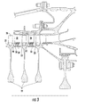
- FIG. 3 is a cross-section of a compressor 2 that depicts honeycomb shrouds 40 assembled to compressor vanes 30. Adjacent to shrouds 40 are rotating labyrinth seals 28 positioned on the rotating portion of the compressor 2 between compressor disks 22. The rotating labyrinth seals 28 each have at least one tooth 50 projecting in an outward radial direction toward the shrouds 40. Compressor blades 20 are shown assembled to the outer circumference 23 of compressor disks 22, and positioned in the gas flow path between vanes 30. As is evident from FIG.
- FIG. 4 is a perspective view of the teeth of a rotating labyrinth seal 28 bearing against a honeycomb shroud 40 joined to a backing strip 60 of a stepped labyrinth seal.
- the direction of rotation of teeth 50 is perpendicular to a line drawn from a vane through the blade teeth, that is, perpendicular to the projection of the blade teeth, or into the plane of the figure substantially in the direction of the arrows.
- the present disclosure provides for a preferentially abradable seal, such as a honeycomb seal, in which distinct regions of differing abradability are present.
- a preferentially abradable honeycomb seal described herein allows for greater control over the wear characteristics of the honeycomb. For example, a preferential wear shape can be achieved or more wear across a part can be promoted in a desired location. Localized wear resistance can simultaneously be promoted in order to limit wear of particular part locations.
- a metal part 100 is illustrated with honeycomb structure 102.
- the honeycomb structure includes two locally strengthened regions 104, 106 and a locally weakened region 108 positioned therebetween.
- any suitable mechanism for creating preferential abrasion can be utilized in connection with the present disclosure including physical or chemical mechanisms.
- Mechanisms for creating preferential abrasion can involve the selective use of positive and/or negative mechanisms of promoting abrasion at chosen locations within the part in question.
- Positive mechanisms of promoting abrasion can include surface grooving, selective etching, ion implantation and/or diffusion, aluminiding, or the like, that would weaken a selected area, thus making it easier for the selected region to be abraded.
- the method of the present disclosure can be performed by exposing the ductile material forming the honeycomb, for example, ribbon material, to a light element such as aluminum, nitrogen, hydrogen or boron at high temperatures to allow the light element to diffuse into the surface of the honeycomb and alter the strength characteristics of the honeycomb by forming a brittle phase that can be more easily machined and abraded.
- aluminide coatings such as titanium aluminide (TiA1) and nickel aluminide (NiA1) can have brittle characteristics in a range of temperatures below the Ductile-Brittle Transition Temperature (DBTT), and that a boronized surface can reduce the ductility of high-strength nickel based sheet metal by embrittling it.
- boron is a light element which can diffuse away quickly in hot sections of the turbine engine in which the temperatures in the region of the seal or shroud can approach 1800° F, it can be utilized in the cold sections of the engine such as the compressor or in non-flow path areas of the turbine where the maximum temperatures reached are generally in a range below about 1300° F (about 700° C). At these operating temperatures, further diffusion of aluminum or even a light element such as boron is minimal, and the diffusion coating will not continue to grow into the substrate base material.
- braze alloys for the honeycomb can have solidus temperatures above about 1900° F.
- the coating can be applied to the honeycomb at a temperature lower than the lowest solidus temperature braze alloy used in the assembly of the part or component, typically lower by about 25-50° F.
- a low pressure turbine vane uses a braze alloy with a solidus temperature of about 2100° F.
- the honeycomb was coated in accordance with the present invention at a temperature in the range of about 1925-1975° F. for about 2-6 hours.
- the coating may be applied by a vapor phase deposition process, by a pack-process, by an activated aluminum-containing tape, referred to as CODAL tape, or by slurry, typically after the honeycomb material has been formed.
- the coating is then diffused into the base material forming the honeycomb.
- the regions of attachment of the honeycomb to the backing plate may be masked, if desired, to protect these regions from exposure to the lightweight elements in order to facilitate brazing.
- the masking material is removed so that brazing of the honeycomb to the backplate can be accomplished in a conventional manner. It is also possible to apply the coating after brazing the honeycomb to the backing structure.
- the easily diffusible element is diffused into the substrate material to an effective depth to form a frangible coating extending to the effective depth overlying the ductile substrate, while maintaining the effective environmental resistance of the honeycomb seal.
- the coating may be formed by any of several methods.
- One method for forming an aluminide coating is vapor phase aluminiding (VPA) which can be accomplished by a pack process or by an over the pack process.
- VPA vapor phase aluminiding
- the substrate is placed into a powder that includes aluminum as well as an inert powder.
- other lightweight powders may be substituted for aluminum to achieve a different type of frangible coating.
- the powder can be packed into the cells of the honeycomb prior to heating.
- the brazed areas may be masked, if desired, to minimize the exposure of these areas to the lightweight element such as aluminum.
- the substrate sheets may be packed into the powder with appropriate masking prior to formation of the honeycomb structure as previously discussed.
- An activator is also included in the powder to enhance the exposure of the substrate to the lightweight element.
- the packed substrate is heated to a predetermined elevated temperature for a preselected time to allow the lightweight element to diffuse into the substrate a predetermined distance, forming a coating having a thickness corresponding to the predetermined distance.
- the depth of diffusion of the element into the substrate is determined by the temperature of exposure and time at temperature.
- Another VPA method for growing a diffusion coating into the substrate is by an over-the-pack process.
- the mechanism of formation in the over-the-pack process of the diffusion coating by growth into the substrate is similar to the mechanism in the pack process.
- the major difference in the over-the-pack process is that the substrate is suspended over the powders rather than being in direct physical contact therewith.
- the gaseous, lightweight elements form a gas phase on heating which flows over the suspended substrate.
- the lightweight elements flow over and are deposited onto the substrate surface and subsequently diffuse into the substrate surface.
- negative mechanisms for promoting abrasion actually would provide reinforcement of a given area.
- Any suitable mechanism for reinforcement can be utilized, including reinforcement coatings, ion implantation, heat treatment and/or annealing, densification, or the like. Such mechanisms reduce the abradability and can increase the wear resistance of a given location.
- one region preferentially abradable, while making, e.g., adjoining areas stronger and more abrasion resistant.
- at least one portion of the seal can be masked such that the other portion of the seal is not subjected to the positive, negative, or both treatments described herein.
- a mask device that is extendable into the honeycomb so as to block one or more chosen interior walls from treatment can be utilized.
- a further advantage of the method described herein is that the relatively stronger area acts as a support when the teeth are cutting into the abradable area.
- regions 104 and 106, the strengthened regions can act as supports to make the cut into region 108 more well-defined. Such enhanced definition of the cut leads ultimately to a better sealing structure.
- the honeycomb structure 102 includes two locally strengthened regions 104, 106 and a locally weakened region 108 positioned therebetween, with cutting surface 110 adjacent thereto.
- Locally weakened region 108 gives way more readily when a seal cut is initiated by cutting surface 110, and cleaner sealing edges 112 are present following the seal cut due to minimal tearing and/or shredding.
- Cutting surface 110 also experiences minimal damage from the slow speed rub. The strength differential of the regions results in a cleaner cut and more efficient sealing.
- the thickness of the honeycomb ribbon substrate forming the shroud is generally from about 0.001 inch to about 0.005 inch, typically about 0.003 inch.
- Honeycomb cell width is typically about 1/16" (0.063"), 1/32" (0.032") or 1/8 inch (0.125").
- the honeycomb cell height is between about 1/4" (0.25") to about 1/2" (0.5").
- rub depth While the depth of the rub may be as great as 0.090 inch, rub depth is typically about 0.015 inch to about 0.020 inch for 360° of travel, with about 0.060 inch depth considered severe.
- At least one weakened portion of the seal can have a depth of at least about 10 percent of the ribbon thickness. In certain embodiments, a weakened portion of the seal can have a depth of at least about 25 percent of the ribbon thickness. In still other embodiments, a weakened portion of the seal can have a depth of at least about 50 percent of the ribbon thickness.
Landscapes
- Engineering & Computer Science (AREA)
- Mechanical Engineering (AREA)
- General Engineering & Computer Science (AREA)
- Turbine Rotor Nozzle Sealing (AREA)
- Structures Of Non-Positive Displacement Pumps (AREA)
- Sealing Using Fluids, Sealing Without Contact, And Removal Of Oil (AREA)
- Sealing Devices (AREA)
Abstract
Description
- The present subject matter relates generally to turbines and, more particularly, to a turbine engine seal.
- Rotating labyrinth seals have a wide variety of uses and one such use is to effect sealing between plenums at different pressures in gas turbine engines. Such seals generally include two principal elements, i.e., a rotating seal and a static seal or shroud. The rotating seal, in cross section parallel to the axial length of the engine, frequently has rows of thin tooth-like projections extending radially from a relatively thicker base toward the static seal or shroud. The static seal or shroud is normally formed from a thin honeycomb ribbon configuration. These principal elements are generally situated circumferentially about the axial length of the engine and are positioned with a small radial gap therebetween to permit assembly of the rotating and static components. The purpose of the labyrinth seal arrangement is to minimize gas path leakage out of the primary gas path and to segregate different stages of the compressor which are at different temperatures and pressures.
- To a significant extent, engine efficiency depends upon minimizing this gas leakage around rotating components by controlling the gas flow to maximize interaction between the gas stream and the components in the primary gas path. The effectiveness of the turbine engine varies directly with the proportion of gas that impinges upon the blades of the rotating member. Closer tolerances between the rotating and static seals achieve greater efficiencies. The fabrication process to obtain these close tolerances is extremely costly and time-consuming.
- When the gas turbine engine is operated, the elevated temperatures of operation cause the opposed static and rotating seals, such as those in the rotating labyrinth seals, to expand in a radial direction toward each other. The rotating labyrinth seals expand radially and rub into the shroud, creating frictional contact between the thin projections of the rotating seal and the shroud. During the rub, there is high thermal compression, with resultant high residual tensile stress after the rub. This frictional contact causes elevation of seal teeth temperatures in excess of 2,000° F with resulting possible damage to one or both seal members. For example, rotating tips may crack and break off, significantly impairing the seal efficiency and operation of the engine.
- The thin, honeycomb ribbon construction of the shroud is used to reduce the surface area on which the seal teeth rub while reducing the weight of the structure, and helps to minimize the heat transferred into the rotating seal, while also providing the required strength. In addition, the rotating labyrinth seal teeth tips are constructed so as to be thin, in order to thermally isolate them from the supporting base or shell structure. However, excessive heat from deep rubs (even into the honeycomb) during engine start-up and during engine excursions can damage the rotating knife edge seals, negatively affecting durability and engine efficiency and providing a leak path for the flow of gases. Furthermore, material transfer can occur which also degrades the seal characteristics. Cutting into even low-density honeycomb cells can still cause rotary seal tooth damage, leading to premature part retirement.
- While much effort has been directed at improving the rotating structure of the seal arrangement, there is a continuous need for improved designs for rotating labyrinth seal structures including improvements directed to the static structure to increase both service life and engine operating efficiencies.
- Aspects and advantages of the invention will be set forth in part in the following description, or may be obvious from the description, or may be learned through practice of the invention.
- In one aspect, the present subject matter discloses a seal including a substrate material. The substrate material has a first portion having a first abradability and a second portion having a second abradability, the first abradability being different from the second abradability.
- In another aspect, the present subject matter discloses a turbine engine seal. The seal includes a section of substrate material. The section of substrate material has a first portion having a first abradability and a second portion having a second abradability, the first abradability being different from the second abradability.
- In still another aspect, the present subject matter discloses a method for producing a seal. The method includes forming a seal from a substrate material. The seal includes a first portion having a first abradability and a second portion having a second abradability, the first abradability being different from the second abradability
- These and other features, aspects and advantages of the present invention will become better understood with reference to the following description and appended claims. The accompanying drawings, which are incorporated in and constitute a part of this specification, illustrate embodiments of the invention and, together with the description, serve to explain the principles of the invention.
- A full and enabling disclosure of the present invention, including the best mode thereof, directed to one of ordinary skill in the art, is set forth in the specification, which makes reference to the appended figures, in which:
-
FIG. 1 illustrates a representation of a turbine compressor rotor and stator; -
FIG. 2 illustrates a representation of a partial section of a honeycomb shroud; -
FIG. 3 illustrates a cross-section of a compressor showing the labyrinth seal teeth adjacent the honeycomb shroud; -
FIG. 4 illustrates a perspective view of a stepped labyrinth seal arrangement showing the teeth of the labyrinth seal adjacent the honeycomb shroud; -
FIG. 5 illustrates a honeycomb structure; and -
FIG. 6 illustrates a honeycomb structure and cutting surface. - Reference now will be made in detail to embodiments of the invention, one or more examples of which are illustrated in the drawings. Each example is provided by way of explanation of the invention, not limitation of the invention. In fact, it will be apparent to those skilled in the art that various modifications and variations can be made in the present invention without departing from the scope or spirit of the invention. For instance, features illustrated or described as part of one embodiment can be used with another embodiment to yield a still further embodiment. Thus, it is intended that the present invention covers such modifications and variations as come within the scope of the appended claims and their equivalents.
- In general, the present subject matter discloses a turbine engine seal and method for producing the same. The seal includes a substrate material, which may, for example, be in the form of a ribbon. The substrate material can have a strengthened portion and/or a weakened portion allowing for abrasion where desired but otherwise minimizing wear in other regions where abrasion is not desired. Such a configuration reduces the opportunity for leakage in the seal zone. Even more broadly, the substrate material can be considered to have a first portion with a first strength and a second portion with a second strength, where the first strength is greater than the second strength. For example, one portion could simply have a "baseline" material strength and another portion could be either stronger or weaker than the "baseline".
- The present disclosure overcomes the issues associated with a uniformly abradable surface. That is, if the entire surface is readily abradable, there is the risk of wearing out a part too quickly and/or having the part fail due to the overall weak structure. On the other hand, if the entire surface is not readily abradable, it can be difficult to achieve desired wear characteristics, especially at low wear and/or friction speeds. The present disclosure eliminates the need to choose between the two parameters by allowing for a desired level of abradability for each region of a given part.
- Referring now to the Figures, where like parts have the same numbers, there is shown generally in
FIG. 1 a segmented view of anaxial flow compressor 2 of a typical engine having acompressor rotor 4 and stator 6. The compressor rotor ofFIG. 1 includes a series ofcompressor blades 20 assembled tocompressor disks 22, with the compressor disks assembled to acommon shaft 24. The rotating labyrinth seals of the present invention are not shown inFIG. 1 , but are located on the compressor rotor at 26, betweencompressor disks 22. The stator 6, which is stationary, includes a series ofvanes 30 that axially direct the flow of air through the compressor as the rotatingcompressor blades 20 move and compress the air in an axial direction. Thecompressor blades 20 rotate between thecompressor vanes 30 forming distinct stages of different pressures and temperatures. Associated withvanes 30, but positioned radially inward from the vanes and opposite the rotating labyrinth seals of thecompressor rotor 4, are shrouds made of thin, honeycomb ribbons. While the methods of this disclosure are particularly adapted to the labyrinth seals, which are formed from a rotating labyrinth seal positioned on therotor 4 betweendisks 22 and a stationary seal or shroud along stators 6 including thin honeycomb ribbon, other structures may be prepared using this method, if desired. - Shown in
FIG. 2 is a section of the generally cylindrical stationary seal orshroud 40 which is positioned in the stator 6 and includes ahoneycomb structure 42 that is generally cylindrical and typically bonded to a backing ring (not shown inFIG. 2 ). One method for forming the honeycomb structure is by corrugating, stacking and joining thin ductile sheets of material such as nickel or nickel base superalloys. A braze alloy compatible with the ductile material sheet is placed at attachment points between the honeycomb structure and the backing ring. On cooling, the sheets, previously attached to each other by a joining process such as tack welding, are connected to the backing ring at attachment points 44 by brazing. -
FIG. 3 is a cross-section of acompressor 2 that depicts honeycomb shrouds 40 assembled tocompressor vanes 30. Adjacent to shrouds 40 are rotating labyrinth seals 28 positioned on the rotating portion of thecompressor 2 betweencompressor disks 22. The rotating labyrinth seals 28 each have at least onetooth 50 projecting in an outward radial direction toward theshrouds 40.Compressor blades 20 are shown assembled to theouter circumference 23 ofcompressor disks 22, and positioned in the gas flow path betweenvanes 30. As is evident fromFIG. 3 , the radial expansion of the rotating portion of the compressor during engine operation will cause theteeth 50 of the rotating labyrinth seals 28 to bear against the honeycomb of the shroud, causing material to be removed from the shroud.FIG. 4 is a perspective view of the teeth of arotating labyrinth seal 28 bearing against ahoneycomb shroud 40 joined to abacking strip 60 of a stepped labyrinth seal. Other engine structure has been removed for clarity. The direction of rotation ofteeth 50 is perpendicular to a line drawn from a vane through the blade teeth, that is, perpendicular to the projection of the blade teeth, or into the plane of the figure substantially in the direction of the arrows. As can be seen, it is desirable for the material from theshroud 40 to be removed in the form of small frangible particles rather than by melting, which requires more energy for removal, thereby heatingteeth 50. - While the foregoing applications refer to the labyrinth seal used in the compressor portion of the gas turbine engine, it will be understood that a similar mechanical design for a labyrinth seal arrangement is used in the turbine or hot portion of the gas turbine engine to separate and isolate the various stages of the turbine sections from one another. The materials used in the hot section are different, utilizing nickel-base superalloys rather than titanium-base alloys, as the nickel-base superalloys have been adapted to survive at the high temperatures and severe environments of the turbine section of the engine.
- The present disclosure provides for a preferentially abradable seal, such as a honeycomb seal, in which distinct regions of differing abradability are present. The preferentially abradable honeycomb seal described herein allows for greater control over the wear characteristics of the honeycomb. For example, a preferential wear shape can be achieved or more wear across a part can be promoted in a desired location. Localized wear resistance can simultaneously be promoted in order to limit wear of particular part locations.
- For example, referring to
FIG. 5 , ametal part 100 is illustrated withhoneycomb structure 102. The honeycomb structure includes two locally strengthenedregions region 108 positioned therebetween. In this regard, any suitable mechanism for creating preferential abrasion can be utilized in connection with the present disclosure including physical or chemical mechanisms. Mechanisms for creating preferential abrasion can involve the selective use of positive and/or negative mechanisms of promoting abrasion at chosen locations within the part in question. Positive mechanisms of promoting abrasion can include surface grooving, selective etching, ion implantation and/or diffusion, aluminiding, or the like, that would weaken a selected area, thus making it easier for the selected region to be abraded. - For instance, the method of the present disclosure can be performed by exposing the ductile material forming the honeycomb, for example, ribbon material, to a light element such as aluminum, nitrogen, hydrogen or boron at high temperatures to allow the light element to diffuse into the surface of the honeycomb and alter the strength characteristics of the honeycomb by forming a brittle phase that can be more easily machined and abraded. It is known that aluminide coatings such as titanium aluminide (TiA1) and nickel aluminide (NiA1) can have brittle characteristics in a range of temperatures below the Ductile-Brittle Transition Temperature (DBTT), and that a boronized surface can reduce the ductility of high-strength nickel based sheet metal by embrittling it. Although boron is a light element which can diffuse away quickly in hot sections of the turbine engine in which the temperatures in the region of the seal or shroud can approach 1800° F, it can be utilized in the cold sections of the engine such as the compressor or in non-flow path areas of the turbine where the maximum temperatures reached are generally in a range below about 1300° F (about 700° C). At these operating temperatures, further diffusion of aluminum or even a light element such as boron is minimal, and the diffusion coating will not continue to grow into the substrate base material.
- Thus, it is possible to grow a diffusion coating into a thin substrate to provide a thin, frangible surface layer, while maintaining a ductile base material underlying the thin surface layer. In higher temperature applications, such as combustor regions and turbine sections, braze alloys for the honeycomb can have solidus temperatures above about 1900° F. For high temperature applications, the coating can be applied to the honeycomb at a temperature lower than the lowest solidus temperature braze alloy used in the assembly of the part or component, typically lower by about 25-50° F. As an example, a low pressure turbine vane uses a braze alloy with a solidus temperature of about 2100° F. The honeycomb was coated in accordance with the present invention at a temperature in the range of about 1925-1975° F. for about 2-6 hours.
- The coating may be applied by a vapor phase deposition process, by a pack-process, by an activated aluminum-containing tape, referred to as CODAL tape, or by slurry, typically after the honeycomb material has been formed. The coating is then diffused into the base material forming the honeycomb. The regions of attachment of the honeycomb to the backing plate may be masked, if desired, to protect these regions from exposure to the lightweight elements in order to facilitate brazing. After the coating is applied by exposing the substrate base material sheet to the lightweight element promoting the formation of the diffusion coating at elevated temperature, the masking material is removed so that brazing of the honeycomb to the backplate can be accomplished in a conventional manner. It is also possible to apply the coating after brazing the honeycomb to the backing structure. By exposing the honeycomb seal to the diffusible element at an elevated temperature, the easily diffusible element is diffused into the substrate material to an effective depth to form a frangible coating extending to the effective depth overlying the ductile substrate, while maintaining the effective environmental resistance of the honeycomb seal.
- As previously noted, the coating may be formed by any of several methods. One method for forming an aluminide coating is vapor phase aluminiding (VPA) which can be accomplished by a pack process or by an over the pack process. In a pack process, the substrate is placed into a powder that includes aluminum as well as an inert powder. However, other lightweight powders may be substituted for aluminum to achieve a different type of frangible coating. In one form, the powder can be packed into the cells of the honeycomb prior to heating. The brazed areas may be masked, if desired, to minimize the exposure of these areas to the lightweight element such as aluminum. In another form, the substrate sheets may be packed into the powder with appropriate masking prior to formation of the honeycomb structure as previously discussed. An activator is also included in the powder to enhance the exposure of the substrate to the lightweight element. The packed substrate is heated to a predetermined elevated temperature for a preselected time to allow the lightweight element to diffuse into the substrate a predetermined distance, forming a coating having a thickness corresponding to the predetermined distance. The depth of diffusion of the element into the substrate is determined by the temperature of exposure and time at temperature.
- Another VPA method for growing a diffusion coating into the substrate is by an over-the-pack process. The mechanism of formation in the over-the-pack process of the diffusion coating by growth into the substrate is similar to the mechanism in the pack process. The major difference in the over-the-pack process is that the substrate is suspended over the powders rather than being in direct physical contact therewith. The gaseous, lightweight elements form a gas phase on heating which flows over the suspended substrate. The lightweight elements flow over and are deposited onto the substrate surface and subsequently diffuse into the substrate surface.
- Referring again to
FIG. 5 , negative mechanisms for promoting abrasion actually would provide reinforcement of a given area. Any suitable mechanism for reinforcement can be utilized, including reinforcement coatings, ion implantation, heat treatment and/or annealing, densification, or the like. Such mechanisms reduce the abradability and can increase the wear resistance of a given location. - Further, it is possible to make one region preferentially abradable, while making, e.g., adjoining areas stronger and more abrasion resistant. In this regard, at least one portion of the seal can be masked such that the other portion of the seal is not subjected to the positive, negative, or both treatments described herein. For instance, a mask device that is extendable into the honeycomb so as to block one or more chosen interior walls from treatment can be utilized.
- The provision of distinct zones/regions of a given level of abradability can allow for tighter cold clearances with adjoining components. Such abrasion control can be of particular usefulness in blade-tip sealing environments, allowing for abrasion where desired, but otherwise minimizing wear in immediately adjacent regions, thereby reducing the opportunity for leakage in the seal zone. Additionally, the differentially abradable seals described herein could be extended to other seal systems beyond honeycomb-type seals.
- A further advantage of the method described herein is that the relatively stronger area acts as a support when the teeth are cutting into the abradable area. As an example, in
FIG. 5 ,regions region 108 more well-defined. Such enhanced definition of the cut leads ultimately to a better sealing structure. - Turning to
FIG. 6 , thehoneycomb structure 102 includes two locally strengthenedregions region 108 positioned therebetween, with cuttingsurface 110 adjacent thereto. Locally weakenedregion 108 gives way more readily when a seal cut is initiated by cuttingsurface 110, and cleaner sealing edges 112 are present following the seal cut due to minimal tearing and/or shredding. Cuttingsurface 110 also experiences minimal damage from the slow speed rub. The strength differential of the regions results in a cleaner cut and more efficient sealing. - The thickness of the honeycomb ribbon substrate forming the shroud is generally from about 0.001 inch to about 0.005 inch, typically about 0.003 inch. Honeycomb cell width is typically about 1/16" (0.063"), 1/32" (0.032") or 1/8 inch (0.125"). The honeycomb cell height is between about 1/4" (0.25") to about 1/2" (0.5").
- While the depth of the rub may be as great as 0.090 inch, rub depth is typically about 0.015 inch to about 0.020 inch for 360° of travel, with about 0.060 inch depth considered severe.
- At least one weakened portion of the seal can have a depth of at least about 10 percent of the ribbon thickness. In certain embodiments, a weakened portion of the seal can have a depth of at least about 25 percent of the ribbon thickness. In still other embodiments, a weakened portion of the seal can have a depth of at least about 50 percent of the ribbon thickness.
- This written description uses examples to disclose the invention, including the best mode, and also to enable any person skilled in the art to practice the invention, including making and using any devices or systems and performing any incorporated methods. The patentable scope of the invention is defined by the claims, and may include other examples that occur to those skilled in the art. Such other examples are intended to be within the scope of the claims if they include structural elements that do not differ from the literal language of the claims, or if they include equivalent structural elements with insubstantial differences from the literal languages of the claims.
Claims (13)
- A seal comprising:a substrate material (102) comprising a first portion (104, 106) having a first abradability and a second portion (108) having a second abradability, the first abradability being different from the second abradability.
- The seal of claim 1, wherein the substrate material comprises a honeycomb seal.
- The seal of claim 1 or claim 2, wherein the first portion has a lesser abradability than the second portion and includes a reinforcement coating.
- The seal of claim 1 or claim 2, wherein the first portion has a lesser abradability than the second portion.
- The seal of any preceding claim, wherein the second portion is located adjacent to the first portion.
- The seal of any preceding claim, wherein the second portion has a greater abradability than the first portion and comprises a depth of at least about 10 percent of the substrate thickness.
- The seal of any preceding claim, wherein the second portion has a greater abradability than the first portion and comprises a depth of at least about 25 percent of the substrate thickness.
- The seal of any preceding claim, wherein the second portion has a greater abradability than the first portion and comprises a depth of at least about 50 percent of the substrate thickness.
- A turbine engine including the seal of any one of the preceding claims.
- A method for producing a seal comprising:forming a seal from substrate material, the seal comprising a first portion having a first abradability and a second portion having a second abradability, the first abradability being different from the second abradability.
- The method of claim 10, wherein the first portion has a lesser abradability than the second portion by applying a reinforcement coating, ion implantation, heat treatment, or combinations thereof.
- The method of claim 10 or 11, wherein the second portion has a greater abradability than the first portion by surface grooving, selective etching, or combinations thereof.
- The method of any one of claims 10 to 12, further comprising masking the first portion or second portion in order to facilitate at least one portion being differently treated so as to have different levels of abradability.
Applications Claiming Priority (1)
| Application Number | Priority Date | Filing Date | Title |
|---|---|---|---|
| US13/343,209 US9175575B2 (en) | 2012-01-04 | 2012-01-04 | Modification of turbine engine seal abradability |
Publications (2)
| Publication Number | Publication Date |
|---|---|
| EP2613008A1 true EP2613008A1 (en) | 2013-07-10 |
| EP2613008B1 EP2613008B1 (en) | 2016-03-16 |
Family
ID=47665820
Family Applications (1)
| Application Number | Title | Priority Date | Filing Date |
|---|---|---|---|
| EP12198344.9A Not-in-force EP2613008B1 (en) | 2012-01-04 | 2012-12-20 | Modification of turbine engine seal abradability |
Country Status (5)
| Country | Link |
|---|---|
| US (1) | US9175575B2 (en) |
| EP (1) | EP2613008B1 (en) |
| JP (1) | JP6063245B2 (en) |
| CN (1) | CN103195740B (en) |
| RU (1) | RU2615088C2 (en) |
Cited By (4)
| Publication number | Priority date | Publication date | Assignee | Title |
|---|---|---|---|---|
| EP3081763A3 (en) * | 2015-04-15 | 2016-10-26 | United Technologies Corporation | Seal configuration to prevent rotor lock |
| FR3040461A1 (en) * | 2015-09-02 | 2017-03-03 | Snecma | LABYRINTH SEALING ELEMENT FOR TURBINE |
| WO2019013665A1 (en) * | 2017-07-14 | 2019-01-17 | Siemens Aktiengesellschaft | Seal arrangement with highly elongated fin tip |
| FR3073890A1 (en) * | 2017-11-21 | 2019-05-24 | Safran Aircraft Engines | ABRADABLE SEAL FOR LABYRINTH, IN PARTICULAR FOR AIRCRAFT TURBINE |
Families Citing this family (8)
| Publication number | Priority date | Publication date | Assignee | Title |
|---|---|---|---|---|
| RU2531312C1 (en) * | 2013-07-16 | 2014-10-20 | Открытое акционерное общество "Научно-производственное объдинение "Сатурн" | Production of cellular filler |
| EP3489465B1 (en) * | 2013-10-03 | 2023-05-17 | Raytheon Technologies Corporation | Seal for a vane seal system and method for managing damping in a vane seal system |
| US9771870B2 (en) * | 2014-03-04 | 2017-09-26 | Rolls-Royce North American Technologies Inc. | Sealing features for a gas turbine engine |
| US20150375259A1 (en) * | 2014-06-27 | 2015-12-31 | General Electric Company | Method and apparatus for manufacturing pre-coated honeycomb segments for turbomachines |
| ITUB20155442A1 (en) * | 2015-11-11 | 2017-05-11 | Ge Avio Srl | STADIUM OF A GAS TURBINE ENGINE PROVIDED WITH A LABYRINTH ESTATE |
| US10774670B2 (en) * | 2017-06-07 | 2020-09-15 | General Electric Company | Filled abradable seal component and associated methods thereof |
| EP3527786B1 (en) * | 2018-02-20 | 2020-05-27 | General Electric Company | Apparatus and method for modifying a static seal or shroud of a turbomachine |
| FR3095025B1 (en) * | 2019-04-12 | 2021-03-05 | Safran Aircraft Engines | Labyrinth seal comprising an abradable element with variable cell density |
Citations (3)
| Publication number | Priority date | Publication date | Assignee | Title |
|---|---|---|---|---|
| US6203021B1 (en) * | 1996-12-10 | 2001-03-20 | Chromalloy Gas Turbine Corporation | Abradable seal having a cut pattern |
| EP1780380A2 (en) * | 2005-10-27 | 2007-05-02 | United Technologies Corporation | Gas turbine blade to vane interface seal |
| EP2317079A2 (en) * | 2009-10-30 | 2011-05-04 | Alstom Technology Ltd | Abradable coating system |
Family Cites Families (11)
| Publication number | Priority date | Publication date | Assignee | Title |
|---|---|---|---|---|
| US4422648A (en) * | 1982-06-17 | 1983-12-27 | United Technologies Corporation | Ceramic faced outer air seal for gas turbine engines |
| US4659289A (en) | 1984-07-23 | 1987-04-21 | United Technologies Corporation | Turbine side plate assembly |
| US6057047A (en) * | 1997-11-18 | 2000-05-02 | United Technologies Corporation | Ceramic coatings containing layered porosity |
| US6199941B1 (en) * | 1998-05-08 | 2001-03-13 | Toyota Jidosha Kabushiki Kaisha | Impact energy absorbing structure in upper vehicle body portion and impact energy absorbing member |
| US6235370B1 (en) * | 1999-03-03 | 2001-05-22 | Siemens Westinghouse Power Corporation | High temperature erosion resistant, abradable thermal barrier composite coating |
| US6485025B1 (en) * | 2000-11-27 | 2002-11-26 | Neomet Limited | Metallic cellular structure |
| US6610416B2 (en) * | 2001-04-26 | 2003-08-26 | General Electric Company | Material treatment for reduced cutting energy and improved temperature capability of honeycomb seals |
| JP5052717B2 (en) * | 2001-05-02 | 2012-10-17 | 日本碍子株式会社 | Honeycomb structure, and honeycomb filter and converter system using the same |
| US7500824B2 (en) | 2006-08-22 | 2009-03-10 | General Electric Company | Angel wing abradable seal and sealing method |
| US20080274336A1 (en) | 2006-12-01 | 2008-11-06 | Siemens Power Generation, Inc. | High temperature insulation with enhanced abradability |
| JP4898743B2 (en) * | 2008-06-09 | 2012-03-21 | 三菱重工業株式会社 | Sealing structure of rotating machine |
-
2012
- 2012-01-04 US US13/343,209 patent/US9175575B2/en not_active Expired - Fee Related
- 2012-12-20 EP EP12198344.9A patent/EP2613008B1/en not_active Not-in-force
- 2012-12-25 JP JP2012280438A patent/JP6063245B2/en not_active Expired - Fee Related
- 2012-12-27 RU RU2012158298A patent/RU2615088C2/en not_active IP Right Cessation
-
2013
- 2013-01-04 CN CN201310001950.1A patent/CN103195740B/en not_active Expired - Fee Related
Patent Citations (3)
| Publication number | Priority date | Publication date | Assignee | Title |
|---|---|---|---|---|
| US6203021B1 (en) * | 1996-12-10 | 2001-03-20 | Chromalloy Gas Turbine Corporation | Abradable seal having a cut pattern |
| EP1780380A2 (en) * | 2005-10-27 | 2007-05-02 | United Technologies Corporation | Gas turbine blade to vane interface seal |
| EP2317079A2 (en) * | 2009-10-30 | 2011-05-04 | Alstom Technology Ltd | Abradable coating system |
Cited By (9)
| Publication number | Priority date | Publication date | Assignee | Title |
|---|---|---|---|---|
| EP3081763A3 (en) * | 2015-04-15 | 2016-10-26 | United Technologies Corporation | Seal configuration to prevent rotor lock |
| US10934875B2 (en) | 2015-04-15 | 2021-03-02 | Raytheon Technologies Corporation | Seal configuration to prevent rotor lock |
| FR3040461A1 (en) * | 2015-09-02 | 2017-03-03 | Snecma | LABYRINTH SEALING ELEMENT FOR TURBINE |
| WO2017037394A1 (en) * | 2015-09-02 | 2017-03-09 | Safran Aircraft Engines | Turbine of gas turbine engine, including a labyrinth sealing joint element |
| US10605106B2 (en) | 2015-09-02 | 2020-03-31 | Safran Aircraft Engines | Turbine of gas turbine engine, comprising a labyrinth seal element |
| WO2019013665A1 (en) * | 2017-07-14 | 2019-01-17 | Siemens Aktiengesellschaft | Seal arrangement with highly elongated fin tip |
| FR3073890A1 (en) * | 2017-11-21 | 2019-05-24 | Safran Aircraft Engines | ABRADABLE SEAL FOR LABYRINTH, IN PARTICULAR FOR AIRCRAFT TURBINE |
| WO2019102124A1 (en) * | 2017-11-21 | 2019-05-31 | Safran Aircraft Engines | Labyrinth seal abradable structure, notably for aircraft turbine |
| US11428110B2 (en) | 2017-11-21 | 2022-08-30 | Safran Aircraft Engines | Labyrinth seal abradable structure, notably for aircraft turbine |
Also Published As
| Publication number | Publication date |
|---|---|
| JP6063245B2 (en) | 2017-01-18 |
| US9175575B2 (en) | 2015-11-03 |
| RU2615088C2 (en) | 2017-04-03 |
| JP2013139788A (en) | 2013-07-18 |
| US20130168927A1 (en) | 2013-07-04 |
| RU2012158298A (en) | 2014-07-10 |
| CN103195740A (en) | 2013-07-10 |
| CN103195740B (en) | 2016-11-23 |
| EP2613008B1 (en) | 2016-03-16 |
Similar Documents
| Publication | Publication Date | Title |
|---|---|---|
| US9175575B2 (en) | Modification of turbine engine seal abradability | |
| EP1254968B2 (en) | Material treatment for reduced cutting energy and improved temperature capability of honeycomb seals | |
| EP2990699B1 (en) | Dual-ended brush seal assembly and method of manufacture | |
| CN101148993B (en) | Methods and apparatus for fabricating turbine engines | |
| EP0495256B1 (en) | Turbine blade shroud assembly | |
| EP1878876B1 (en) | Gas turbine abradable seal and manufacturing method thereof | |
| EP2570607B1 (en) | Gas turbine engine with ceramic matrix composite static structure and rotor module, and corresponding method of tip clearance control | |
| US10544698B2 (en) | Air seal abrasive coating and method | |
| EP2904216B1 (en) | Aluminum based abradable material with reduced metal transfer to blades | |
| EP2256295A2 (en) | Turbine rotor seal plate with integral flow discourager | |
| US20100150730A1 (en) | Component having an abrasive layer and a method of applying an abrasive layer on a component | |
| JP2010019261A (en) | Spring seal for turbine dovetail | |
| JP2013119855A (en) | Honeycomb structure for abradable angel wing | |
| US10718352B2 (en) | Multi-cellular abradable liner | |
| US6485655B1 (en) | Method and apparatus for retaining an internal coating during article repair | |
| EP2984296A1 (en) | Blade outer air seal with secondary air sealing | |
| JP2014062544A (en) | Turbomachine blade tip insert | |
| EP3090140A1 (en) | Blade outer air seal with secondary air sealing | |
| EP3034809B1 (en) | Gas turbine engine component with abrasive surface formed by electrical discharge machining | |
| US10822964B2 (en) | Blade outer air seal with non-linear response | |
| US20220154583A1 (en) | Turbine rotor blade and contact surface manufacturing method | |
| JP6947851B2 (en) | Turbine blades with skiler tips and high density oxide dispersion reinforcement layers | |
| US20200049256A1 (en) | Wire mesh brush seal windage cover |
Legal Events
| Date | Code | Title | Description |
|---|---|---|---|
| PUAI | Public reference made under article 153(3) epc to a published international application that has entered the european phase |
Free format text: ORIGINAL CODE: 0009012 |
|
| AK | Designated contracting states |
Kind code of ref document: A1 Designated state(s): AL AT BE BG CH CY CZ DE DK EE ES FI FR GB GR HR HU IE IS IT LI LT LU LV MC MK MT NL NO PL PT RO RS SE SI SK SM TR |
|
| AX | Request for extension of the european patent |
Extension state: BA ME |
|
| 17P | Request for examination filed |
Effective date: 20140110 |
|
| RBV | Designated contracting states (corrected) |
Designated state(s): AL AT BE BG CH CY CZ DE DK EE ES FI FR GB GR HR HU IE IS IT LI LT LU LV MC MK MT NL NO PL PT RO RS SE SI SK SM TR |
|
| 17Q | First examination report despatched |
Effective date: 20141001 |
|
| GRAP | Despatch of communication of intention to grant a patent |
Free format text: ORIGINAL CODE: EPIDOSNIGR1 |
|
| INTG | Intention to grant announced |
Effective date: 20151012 |
|
| GRAS | Grant fee paid |
Free format text: ORIGINAL CODE: EPIDOSNIGR3 |
|
| GRAA | (expected) grant |
Free format text: ORIGINAL CODE: 0009210 |
|
| AK | Designated contracting states |
Kind code of ref document: B1 Designated state(s): AL AT BE BG CH CY CZ DE DK EE ES FI FR GB GR HR HU IE IS IT LI LT LU LV MC MK MT NL NO PL PT RO RS SE SI SK SM TR |
|
| REG | Reference to a national code |
Ref country code: GB Ref legal event code: FG4D |
|
| REG | Reference to a national code |
Ref country code: CH Ref legal event code: EP |
|
| REG | Reference to a national code |
Ref country code: IE Ref legal event code: FG4D |
|
| REG | Reference to a national code |
Ref country code: AT Ref legal event code: REF Ref document number: 781453 Country of ref document: AT Kind code of ref document: T Effective date: 20160415 |
|
| REG | Reference to a national code |
Ref country code: DE Ref legal event code: R096 Ref document number: 602012015625 Country of ref document: DE |
|
| REG | Reference to a national code |
Ref country code: NL Ref legal event code: MP Effective date: 20160316 |
|
| REG | Reference to a national code |
Ref country code: LT Ref legal event code: MG4D |
|
| PG25 | Lapsed in a contracting state [announced via postgrant information from national office to epo] |
Ref country code: FI Free format text: LAPSE BECAUSE OF FAILURE TO SUBMIT A TRANSLATION OF THE DESCRIPTION OR TO PAY THE FEE WITHIN THE PRESCRIBED TIME-LIMIT Effective date: 20160316 Ref country code: NO Free format text: LAPSE BECAUSE OF FAILURE TO SUBMIT A TRANSLATION OF THE DESCRIPTION OR TO PAY THE FEE WITHIN THE PRESCRIBED TIME-LIMIT Effective date: 20160616 Ref country code: GR Free format text: LAPSE BECAUSE OF FAILURE TO SUBMIT A TRANSLATION OF THE DESCRIPTION OR TO PAY THE FEE WITHIN THE PRESCRIBED TIME-LIMIT Effective date: 20160617 Ref country code: HR Free format text: LAPSE BECAUSE OF FAILURE TO SUBMIT A TRANSLATION OF THE DESCRIPTION OR TO PAY THE FEE WITHIN THE PRESCRIBED TIME-LIMIT Effective date: 20160316 |
|
| REG | Reference to a national code |
Ref country code: AT Ref legal event code: MK05 Ref document number: 781453 Country of ref document: AT Kind code of ref document: T Effective date: 20160316 |
|
| PG25 | Lapsed in a contracting state [announced via postgrant information from national office to epo] |
Ref country code: RS Free format text: LAPSE BECAUSE OF FAILURE TO SUBMIT A TRANSLATION OF THE DESCRIPTION OR TO PAY THE FEE WITHIN THE PRESCRIBED TIME-LIMIT Effective date: 20160316 Ref country code: SE Free format text: LAPSE BECAUSE OF FAILURE TO SUBMIT A TRANSLATION OF THE DESCRIPTION OR TO PAY THE FEE WITHIN THE PRESCRIBED TIME-LIMIT Effective date: 20160316 Ref country code: NL Free format text: LAPSE BECAUSE OF FAILURE TO SUBMIT A TRANSLATION OF THE DESCRIPTION OR TO PAY THE FEE WITHIN THE PRESCRIBED TIME-LIMIT Effective date: 20160316 Ref country code: LV Free format text: LAPSE BECAUSE OF FAILURE TO SUBMIT A TRANSLATION OF THE DESCRIPTION OR TO PAY THE FEE WITHIN THE PRESCRIBED TIME-LIMIT Effective date: 20160316 Ref country code: LT Free format text: LAPSE BECAUSE OF FAILURE TO SUBMIT A TRANSLATION OF THE DESCRIPTION OR TO PAY THE FEE WITHIN THE PRESCRIBED TIME-LIMIT Effective date: 20160316 |
|
| PG25 | Lapsed in a contracting state [announced via postgrant information from national office to epo] |
Ref country code: EE Free format text: LAPSE BECAUSE OF FAILURE TO SUBMIT A TRANSLATION OF THE DESCRIPTION OR TO PAY THE FEE WITHIN THE PRESCRIBED TIME-LIMIT Effective date: 20160316 Ref country code: IS Free format text: LAPSE BECAUSE OF FAILURE TO SUBMIT A TRANSLATION OF THE DESCRIPTION OR TO PAY THE FEE WITHIN THE PRESCRIBED TIME-LIMIT Effective date: 20160716 Ref country code: PL Free format text: LAPSE BECAUSE OF FAILURE TO SUBMIT A TRANSLATION OF THE DESCRIPTION OR TO PAY THE FEE WITHIN THE PRESCRIBED TIME-LIMIT Effective date: 20160316 |
|
| PG25 | Lapsed in a contracting state [announced via postgrant information from national office to epo] |
Ref country code: PT Free format text: LAPSE BECAUSE OF FAILURE TO SUBMIT A TRANSLATION OF THE DESCRIPTION OR TO PAY THE FEE WITHIN THE PRESCRIBED TIME-LIMIT Effective date: 20160718 Ref country code: SK Free format text: LAPSE BECAUSE OF FAILURE TO SUBMIT A TRANSLATION OF THE DESCRIPTION OR TO PAY THE FEE WITHIN THE PRESCRIBED TIME-LIMIT Effective date: 20160316 Ref country code: RO Free format text: LAPSE BECAUSE OF FAILURE TO SUBMIT A TRANSLATION OF THE DESCRIPTION OR TO PAY THE FEE WITHIN THE PRESCRIBED TIME-LIMIT Effective date: 20160316 Ref country code: CZ Free format text: LAPSE BECAUSE OF FAILURE TO SUBMIT A TRANSLATION OF THE DESCRIPTION OR TO PAY THE FEE WITHIN THE PRESCRIBED TIME-LIMIT Effective date: 20160316 Ref country code: SM Free format text: LAPSE BECAUSE OF FAILURE TO SUBMIT A TRANSLATION OF THE DESCRIPTION OR TO PAY THE FEE WITHIN THE PRESCRIBED TIME-LIMIT Effective date: 20160316 Ref country code: ES Free format text: LAPSE BECAUSE OF FAILURE TO SUBMIT A TRANSLATION OF THE DESCRIPTION OR TO PAY THE FEE WITHIN THE PRESCRIBED TIME-LIMIT Effective date: 20160316 Ref country code: AT Free format text: LAPSE BECAUSE OF FAILURE TO SUBMIT A TRANSLATION OF THE DESCRIPTION OR TO PAY THE FEE WITHIN THE PRESCRIBED TIME-LIMIT Effective date: 20160316 |
|
| REG | Reference to a national code |
Ref country code: DE Ref legal event code: R097 Ref document number: 602012015625 Country of ref document: DE |
|
| REG | Reference to a national code |
Ref country code: FR Ref legal event code: PLFP Year of fee payment: 5 |
|
| PG25 | Lapsed in a contracting state [announced via postgrant information from national office to epo] |
Ref country code: BE Free format text: LAPSE BECAUSE OF FAILURE TO SUBMIT A TRANSLATION OF THE DESCRIPTION OR TO PAY THE FEE WITHIN THE PRESCRIBED TIME-LIMIT Effective date: 20160316 |
|
| PLBE | No opposition filed within time limit |
Free format text: ORIGINAL CODE: 0009261 |
|
| STAA | Information on the status of an ep patent application or granted ep patent |
Free format text: STATUS: NO OPPOSITION FILED WITHIN TIME LIMIT |
|
| PG25 | Lapsed in a contracting state [announced via postgrant information from national office to epo] |
Ref country code: DK Free format text: LAPSE BECAUSE OF FAILURE TO SUBMIT A TRANSLATION OF THE DESCRIPTION OR TO PAY THE FEE WITHIN THE PRESCRIBED TIME-LIMIT Effective date: 20160316 |
|
| 26N | No opposition filed |
Effective date: 20161219 |
|
| PG25 | Lapsed in a contracting state [announced via postgrant information from national office to epo] |
Ref country code: BG Free format text: LAPSE BECAUSE OF FAILURE TO SUBMIT A TRANSLATION OF THE DESCRIPTION OR TO PAY THE FEE WITHIN THE PRESCRIBED TIME-LIMIT Effective date: 20160616 |
|
| PG25 | Lapsed in a contracting state [announced via postgrant information from national office to epo] |
Ref country code: SI Free format text: LAPSE BECAUSE OF FAILURE TO SUBMIT A TRANSLATION OF THE DESCRIPTION OR TO PAY THE FEE WITHIN THE PRESCRIBED TIME-LIMIT Effective date: 20160316 |
|
| GBPC | Gb: european patent ceased through non-payment of renewal fee |
Effective date: 20161220 |
|
| PG25 | Lapsed in a contracting state [announced via postgrant information from national office to epo] |
Ref country code: MC Free format text: LAPSE BECAUSE OF FAILURE TO SUBMIT A TRANSLATION OF THE DESCRIPTION OR TO PAY THE FEE WITHIN THE PRESCRIBED TIME-LIMIT Effective date: 20160316 |
|
| REG | Reference to a national code |
Ref country code: IE Ref legal event code: MM4A |
|
| PG25 | Lapsed in a contracting state [announced via postgrant information from national office to epo] |
Ref country code: LU Free format text: LAPSE BECAUSE OF NON-PAYMENT OF DUE FEES Effective date: 20161220 |
|
| PG25 | Lapsed in a contracting state [announced via postgrant information from national office to epo] |
Ref country code: GB Free format text: LAPSE BECAUSE OF NON-PAYMENT OF DUE FEES Effective date: 20161220 Ref country code: IE Free format text: LAPSE BECAUSE OF NON-PAYMENT OF DUE FEES Effective date: 20161220 |
|
| REG | Reference to a national code |
Ref country code: FR Ref legal event code: PLFP Year of fee payment: 6 |
|
| PG25 | Lapsed in a contracting state [announced via postgrant information from national office to epo] |
Ref country code: HU Free format text: LAPSE BECAUSE OF FAILURE TO SUBMIT A TRANSLATION OF THE DESCRIPTION OR TO PAY THE FEE WITHIN THE PRESCRIBED TIME-LIMIT; INVALID AB INITIO Effective date: 20121220 Ref country code: CY Free format text: LAPSE BECAUSE OF FAILURE TO SUBMIT A TRANSLATION OF THE DESCRIPTION OR TO PAY THE FEE WITHIN THE PRESCRIBED TIME-LIMIT Effective date: 20160316 |
|
| PG25 | Lapsed in a contracting state [announced via postgrant information from national office to epo] |
Ref country code: MK Free format text: LAPSE BECAUSE OF FAILURE TO SUBMIT A TRANSLATION OF THE DESCRIPTION OR TO PAY THE FEE WITHIN THE PRESCRIBED TIME-LIMIT Effective date: 20160316 |
|
| PG25 | Lapsed in a contracting state [announced via postgrant information from national office to epo] |
Ref country code: MT Free format text: LAPSE BECAUSE OF NON-PAYMENT OF DUE FEES Effective date: 20161220 |
|
| PG25 | Lapsed in a contracting state [announced via postgrant information from national office to epo] |
Ref country code: AL Free format text: LAPSE BECAUSE OF FAILURE TO SUBMIT A TRANSLATION OF THE DESCRIPTION OR TO PAY THE FEE WITHIN THE PRESCRIBED TIME-LIMIT Effective date: 20160316 Ref country code: TR Free format text: LAPSE BECAUSE OF FAILURE TO SUBMIT A TRANSLATION OF THE DESCRIPTION OR TO PAY THE FEE WITHIN THE PRESCRIBED TIME-LIMIT Effective date: 20160316 |
|
| PGFP | Annual fee paid to national office [announced via postgrant information from national office to epo] |
Ref country code: CH Payment date: 20191121 Year of fee payment: 8 |
|
| PGFP | Annual fee paid to national office [announced via postgrant information from national office to epo] |
Ref country code: DE Payment date: 20201119 Year of fee payment: 9 Ref country code: IT Payment date: 20201123 Year of fee payment: 9 Ref country code: FR Payment date: 20201120 Year of fee payment: 9 |
|
| REG | Reference to a national code |
Ref country code: CH Ref legal event code: PL |
|
| PG25 | Lapsed in a contracting state [announced via postgrant information from national office to epo] |
Ref country code: CH Free format text: LAPSE BECAUSE OF NON-PAYMENT OF DUE FEES Effective date: 20201231 Ref country code: LI Free format text: LAPSE BECAUSE OF NON-PAYMENT OF DUE FEES Effective date: 20201231 |
|
| REG | Reference to a national code |
Ref country code: DE Ref legal event code: R119 Ref document number: 602012015625 Country of ref document: DE |
|
| PG25 | Lapsed in a contracting state [announced via postgrant information from national office to epo] |
Ref country code: DE Free format text: LAPSE BECAUSE OF NON-PAYMENT OF DUE FEES Effective date: 20220701 |
|
| PG25 | Lapsed in a contracting state [announced via postgrant information from national office to epo] |
Ref country code: FR Free format text: LAPSE BECAUSE OF NON-PAYMENT OF DUE FEES Effective date: 20211231 |
|
| PG25 | Lapsed in a contracting state [announced via postgrant information from national office to epo] |
Ref country code: IT Free format text: LAPSE BECAUSE OF NON-PAYMENT OF DUE FEES Effective date: 20211220 |