EP2612995A2 - Turbine nozzle compartmentalized cooling system - Google Patents
Turbine nozzle compartmentalized cooling system Download PDFInfo
- Publication number
- EP2612995A2 EP2612995A2 EP13150146.2A EP13150146A EP2612995A2 EP 2612995 A2 EP2612995 A2 EP 2612995A2 EP 13150146 A EP13150146 A EP 13150146A EP 2612995 A2 EP2612995 A2 EP 2612995A2
- Authority
- EP
- European Patent Office
- Prior art keywords
- cooling
- nozzle
- compartmentalized
- baffle
- flow
- Prior art date
- Legal status (The legal status is an assumption and is not a legal conclusion. Google has not performed a legal analysis and makes no representation as to the accuracy of the status listed.)
- Granted
Links
- 238000001816 cooling Methods 0.000 title claims abstract description 132
- 239000000567 combustion gas Substances 0.000 claims abstract description 16
- 238000004891 communication Methods 0.000 claims abstract description 7
- 238000007789 sealing Methods 0.000 claims description 20
- 238000000034 method Methods 0.000 claims description 3
- 239000007789 gas Substances 0.000 description 18
- 238000013461 design Methods 0.000 description 5
- 239000002826 coolant Substances 0.000 description 2
- 239000000446 fuel Substances 0.000 description 2
- VNWKTOKETHGBQD-UHFFFAOYSA-N methane Chemical compound C VNWKTOKETHGBQD-UHFFFAOYSA-N 0.000 description 2
- 238000013459 approach Methods 0.000 description 1
- 238000000605 extraction Methods 0.000 description 1
- 239000003779 heat-resistant material Substances 0.000 description 1
- 238000003754 machining Methods 0.000 description 1
- 239000000463 material Substances 0.000 description 1
- 239000000203 mixture Substances 0.000 description 1
- 238000012986 modification Methods 0.000 description 1
- 230000004048 modification Effects 0.000 description 1
- 239000003345 natural gas Substances 0.000 description 1
- 230000003071 parasitic effect Effects 0.000 description 1
- 238000010248 power generation Methods 0.000 description 1
- 238000012552 review Methods 0.000 description 1
- 238000011144 upstream manufacturing Methods 0.000 description 1
Images


Classifications
-
- F—MECHANICAL ENGINEERING; LIGHTING; HEATING; WEAPONS; BLASTING
- F01—MACHINES OR ENGINES IN GENERAL; ENGINE PLANTS IN GENERAL; STEAM ENGINES
- F01D—NON-POSITIVE DISPLACEMENT MACHINES OR ENGINES, e.g. STEAM TURBINES
- F01D5/00—Blades; Blade-carrying members; Heating, heat-insulating, cooling or antivibration means on the blades or the members
- F01D5/12—Blades
- F01D5/14—Form or construction
- F01D5/18—Hollow blades, i.e. blades with cooling or heating channels or cavities; Heating, heat-insulating or cooling means on blades
- F01D5/187—Convection cooling
- F01D5/188—Convection cooling with an insert in the blade cavity to guide the cooling fluid, e.g. forming a separation wall
- F01D5/189—Convection cooling with an insert in the blade cavity to guide the cooling fluid, e.g. forming a separation wall the insert having a tubular cross-section, e.g. airfoil shape
-
- F—MECHANICAL ENGINEERING; LIGHTING; HEATING; WEAPONS; BLASTING
- F01—MACHINES OR ENGINES IN GENERAL; ENGINE PLANTS IN GENERAL; STEAM ENGINES
- F01D—NON-POSITIVE DISPLACEMENT MACHINES OR ENGINES, e.g. STEAM TURBINES
- F01D9/00—Stators
- F01D9/06—Fluid supply conduits to nozzles or the like
- F01D9/065—Fluid supply or removal conduits traversing the working fluid flow, e.g. for lubrication-, cooling-, or sealing fluids
-
- F—MECHANICAL ENGINEERING; LIGHTING; HEATING; WEAPONS; BLASTING
- F01—MACHINES OR ENGINES IN GENERAL; ENGINE PLANTS IN GENERAL; STEAM ENGINES
- F01D—NON-POSITIVE DISPLACEMENT MACHINES OR ENGINES, e.g. STEAM TURBINES
- F01D5/00—Blades; Blade-carrying members; Heating, heat-insulating, cooling or antivibration means on the blades or the members
- F01D5/12—Blades
- F01D5/14—Form or construction
- F01D5/18—Hollow blades, i.e. blades with cooling or heating channels or cavities; Heating, heat-insulating or cooling means on blades
-
- F—MECHANICAL ENGINEERING; LIGHTING; HEATING; WEAPONS; BLASTING
- F01—MACHINES OR ENGINES IN GENERAL; ENGINE PLANTS IN GENERAL; STEAM ENGINES
- F01D—NON-POSITIVE DISPLACEMENT MACHINES OR ENGINES, e.g. STEAM TURBINES
- F01D9/00—Stators
- F01D9/02—Nozzles; Nozzle boxes; Stator blades; Guide conduits, e.g. individual nozzles
-
- F—MECHANICAL ENGINEERING; LIGHTING; HEATING; WEAPONS; BLASTING
- F05—INDEXING SCHEMES RELATING TO ENGINES OR PUMPS IN VARIOUS SUBCLASSES OF CLASSES F01-F04
- F05D—INDEXING SCHEME FOR ASPECTS RELATING TO NON-POSITIVE-DISPLACEMENT MACHINES OR ENGINES, GAS-TURBINES OR JET-PROPULSION PLANTS
- F05D2260/00—Function
- F05D2260/20—Heat transfer, e.g. cooling
- F05D2260/201—Heat transfer, e.g. cooling by impingement of a fluid
-
- Y—GENERAL TAGGING OF NEW TECHNOLOGICAL DEVELOPMENTS; GENERAL TAGGING OF CROSS-SECTIONAL TECHNOLOGIES SPANNING OVER SEVERAL SECTIONS OF THE IPC; TECHNICAL SUBJECTS COVERED BY FORMER USPC CROSS-REFERENCE ART COLLECTIONS [XRACs] AND DIGESTS
- Y02—TECHNOLOGIES OR APPLICATIONS FOR MITIGATION OR ADAPTATION AGAINST CLIMATE CHANGE
- Y02T—CLIMATE CHANGE MITIGATION TECHNOLOGIES RELATED TO TRANSPORTATION
- Y02T50/00—Aeronautics or air transport
- Y02T50/60—Efficient propulsion technologies, e.g. for aircraft
Landscapes
- Engineering & Computer Science (AREA)
- Mechanical Engineering (AREA)
- General Engineering & Computer Science (AREA)
- Physics & Mathematics (AREA)
- Fluid Mechanics (AREA)
- Turbine Rotor Nozzle Sealing (AREA)
Abstract
Description
- The present application and the resultant patent relate generally to gas turbine engines and more particularly relate to a turbine nozzle compartmentalized cooling system for a split case turbine design so as to provide high pressure cooling air with low leakage.
- Generally described, a turbine stage of a gas turbine engine includes a number of stationary turbine nozzles. Each turbine nozzle may have a vane extending radially between outer and inner sidewalls. The nozzle vanes may have an airfoil configuration for guiding the combustion gases between corresponding turbine rotor blades disposed upstream and downstream thereof. The turbine rotor blades may be mounted to the perimeter of a rotor disk for rotation therewith. Because the turbine nozzle vanes are heated during operation by the hot combustion gases that flow therethrough, cooling air bled from the compressor may be channeled inside the vanes for cooling purposes. Limiting the amount of parasitic cooling air required and limiting the leakage of such cooling air lost in the nozzle vanes and elsewhere should promote overall gas turbine engine efficiency and performance.
- Compartmentalized cooling has been used in the past with aviation turbine engines and the like. Such aviation engines generally include a circular (360°) component to direct the cooling flow into the nozzles. This configuration may be possible with aviation engines given that aviation engines generally are full hoop case structures that are axially stacked during assembly. Due to the overall size of industrial gas turbine engines, however, such industrial gas turbines generally are installed in at least two half (180°) segments, if not many more. This segmented configuration generally precludes the use of a 360° component to route the cooling flow into the nozzle arrangement.
- There is thus a desire for an improved industrial gas turbine design. Such an improved industrial gas turbine design may use a number of segmented cooling baffles to provide high pressure cooling air with low leakage so as to promote efficient cooling with low leakage.
- The present application and the resultant patent thus provide a compartmentalized cooling system for providing a cooling flow in a turbine with a flow of combustion gases therein. The compartmentalized cooling system may include a turbine nozzle and a cooling baffle. The turbine nozzle may include an airfoil insert and a nozzle outer sidewall. The cooling baffle may include a high pressure cooling passage in communication with the airfoil insert in a first circuit and an impingement plate positioned about the nozzle outer sidewall in a second circuit. The cooling baffle thus provides a high pressure cooling flow with low leakage.
- The present application and the resultant patent further provide a method of cooling a nozzle of a turbine. The method may include the steps of delivering a first circuit cooling flow under high pressure to an airfoil insert of a nozzle vane through a cooling baffle, cooling the nozzle vane with the first circuit cooling flow, delivering a second circuit cooling flow to an impingement plate of the cooling baffle positioned about a nozzle outer side wall, and cooling the outer nozzle side wall with the second circuit cooling flow.
- The present application and the resultant patent further provide a compartmentalized cooling system for providing a cooling flow in a turbine with a flow of combustion gases therein. The compartmentalized cooling system may include a turbine nozzle and a number of cooling baffle segments. The turbine nozzle may include an airfoil insert and a nozzle outer sidewall. Each of the cooling baffle segments may include a high pressure cooling passage in communication with the airfoil insert in a first circuit and an impingement plate positioned about the nozzle outer sidewall in a second circuit.
- These and other features and improvements of the present application and the resultant patent will become apparent to one of ordinary skill in the art upon review of the following detailed description when taken in conjunction with the several drawings and the appended claims.
-
-
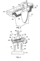
Fig. 1 is a schematic view of a gas turbine engine including a compressor, a combustor, and a turbine. -
Fig. 2 is a partial perspective side cross-sectional view of a coolant baffle as may be described herein positioned about a nozzle vane. -
Fig. 3 is a partial perspective side cross-sectional view of the cooling baffle and the nozzle vane ofFig. 2 . -
Fig. 4 is a partial side view of the cooling baffle and the nozzle vane ofFig. 2 showing the airflow circuits therethrough. -
Fig. 5 is a partial side cross-sectional view of portions of two cooling baffles and nozzle vane segments ofFig. 2 and the intersegment gaps therebetween and showing the airflow circuits therethrough. - Referring now to the drawings, in which like numerals refer to like elements throughout the several views,
Fig. 1 shows a schematic view ofgas turbine engine 10 as may be used herein. Thegas turbine engine 10 may include acompressor 15. Thecompressor 15 compresses an incoming flow ofair 20. Thecompressor 15 delivers the compressed flow ofair 20 to acombustor 25. Thecombustor 25 mixes the compressed flow ofair 20 with a compressed flow offuel 30 and ignites the mixture to create a flow ofcombustion gases 35. Although only asingle combustor 25 is shown, thegas turbine engine 10 may include any number ofcombustors 25. The flow ofcombustion gases 35 is in turn delivered to aturbine 40. The flow ofcombustion gases 35 drives theturbine 40 so as to produce mechanical work. The mechanical work produced in theturbine 40 drives thecompressor 15 via ashaft 45 and anexternal load 50 such as an electrical generator and the like. - The
gas turbine engine 10 may use natural gas, various types of syngas, and/or other types of fuels. Thegas turbine engine 10 may be any one of a number of different gas turbine engines offered by General Electric Company of Schenectady, New York, including, but not limited to, those such as a 7 or a 9 series heavy duty gas turbine engine and the like. Thegas turbine engine 10 may have different configurations and may use other types of components. Other types of gas turbine engines also may be used herein. Multiple gas turbine engines, other types of turbines, and other types of power generation equipment also may be used herein together. -
Figs. 2-5 show portions of a turbine nozzle compartmentalizedcooling system 100 as may be described herein. The turbine nozzle compartmentalizedcooling system 100 may be used with a number ofturbine nozzles 105 of theturbine 40 described above and the like. Theturbine nozzles 105 may be part of a split case design. Each of theturbine nozzles 105 may include anozzle vane 110. Thenozzle vane 110 may extend between aninner sidewall 120 and anouter sidewall 140 in a cantilevered fashion. A number of theturbine nozzles 105 may be combined into a circumferential array to form a stage with a number of rotor blades (not shown). - The
nozzle 105 may include the nozzleouter sidewall 140 extending about thenozzle vane 110. Thenozzle vane 110 may be substantially hollow. Anairfoil insert 150 may be positioned within thenozzle vane 110. Theairfoil insert 150 may have a number ofcooling apertures 160 formed therein. Thecooling apertures 160 may be used to direct acooling flow 170 about thenozzle vane 110 via impingement cooling and the like. Theairfoil insert 150 may be in communication with thecooling flow 170 from thecompressor 15 via a tube seal or other type of highpressure cooling passage 180 as part of a cooling circuit. More than onecooling passage 180 may be used herein. Other components and other configurations may be used herein. - The turbine nozzle compartmentalized
cooling system 100 also may include acooling baffle 200 positioned about theturbine nozzle 105. Thecooling baffle 200 may be positioned between the cooling supply from thecompressor 15 and theouter sidewall 140 of theturbine nozzle 105. Thecooling baffle 200 may be in the form of a number ofsegments 210. Specifically, thecooling baffle 200 may be segmented into at least two (2)segments 210 and up to one (1)segment 210 pernozzle vane 110 in a given stage. The gaps between each of thecooling baffle segments 210 may be sealed with a spline seal and the like. - The
cooling baffle 200 may serve as animpingement plate 230. Theimpingement plate 230 may have a number ofcooling apertures 240 formed therein. Any number or configuration of coolingapertures 240 may be used herein. Afirst sealing layer 250 may be positioned about theimpingement plate 230. Asecond sealing layer 260 may be positioned about theouter sidewall 140. The sealing layers 250, 260 may be made out of any robust, heat resistant material. Theimpingement plate 230 and the sealing layers 250, 260 may surround the highpressure cooling passage 180 in communication with theairfoil insert 150. Apost-impingement pressure cavity 265 may be defined between theimpingement plate 230 and thefirst sealing layer 250 at one end and theouter sidewall 140 and thesecond sealing layer 260 at the other end. - In use, the
cooling flow 170 from thecompressor 15 may pass through ahigh pressure area 270 above thecooling baffle 200 and thefirst sealing layer 250, a medium pressure area 280 in thepost-impingement pressure cavity 265 between the sealinglayers low pressure area 290 beneath thepost-impingement pressure cavity 265 and thesecond sealing layer 260 about the flow of combustion gases. As thecooling flow 170 approaches theturbine nozzle 105, thecooling flow 170 has three (3) possible flow paths. First, thecooling flow 170 may directly enter into theairfoil insert 150 within thenozzle vane 110 for cooling therein via thecooling passage 180 under high pressure. Second, thecooling flow 170 may pass through theimpingement plate 230 of thecoolant baffle 200 and impingement cool the nozzleouter sidewall 140. Third, thecooling flow 170 may leak across thefirst sealing layer 250 into the postimpingement pressure cavity 265. The medium pressure post-impingement air then may leak across thesecond sealing layer 260 into the low pressure flow of thecombustion gases 35. Other configurations and other components also may be used herein. - By routing the
cooling flow 170 directly into theairfoil insert 150 via the highpressure cooling passage 180 in afirst circuit 300, thecooling flow 170 from thehigh pressure area 270 may be used for cooling in thenozzle insert 150 without a significant pressure drop. By using the sealing layers 250, 260 in series in asecond circuit 330, afirst leakage path 310 driven by thehigh pressure area 270 may extend across thebaffle 200 and thefirst sealing layer 250 while asecond leakage path 320 extends across thesecond sealing layer 260 towards the flow ofcombustion gases 35 under low pressure. In other words, thecooling flow 170 in thesecond leakage path 320 extends from the medium pressure area 280 across thesecond sealing layer 260 and into thelow pressure area 290 of the flow ofcombustion gases 35. As such, the pressure difference between the postimpingement pressure cavity 265 and the flow ofcombustion gases 35 is less than the pressure difference between the coolingflow 170 and thehigh pressure area 270 and the flow ofcombustion gases 35. Any leakage from the nozzleouter sidewall 140 thus may be driven by the pressure of the postimpingement pressure cavity 265 instead of the compressor extraction from thehigh pressure area 270. As a result, the sealinglayers cooling baffle 200 of the turbine nozzle compartmentalized coolingsystem 100 may provide lower leakage while using the air from thehigh pressure area 270 for cooling without a significant pressure drop. - The
cooling baffle 200 of the turbine nozzle compartmentalized coolingsystem 100 may be a separate element or cast into place. Specifically, hollow bridge like structures may be cast into the nozzleouter sidewall 140 while machining cooling apertures therethrough such that the seal layers 250, 260 could be placed therein. An impingement plate could be attached to the top of the bridges or sidewalls. Alternatively, a fully enclosed plenum also could be cast to the nozzleouter sidewalls 140 and then drilled with impingement holes and the like with the seal layers 250, 260 and the like therein. - The
turbine nozzle 105 with thecooling baffle 200 thus enables compartmentalized cooling in a split case turbine design. Such compartmentalized cooling reduces leakage while providing high pressure cooling air to multiple cooling circuits without an appreciable pressure drop. Lower leakage and higher pressure cooling air should provide increased efficiency, increased performance, and longer component lifetime with limited costs and materials. - It should be apparent that the foregoing relates only to certain embodiments of the present application and the resultant patent. Numerous changes and modifications may be made herein by one of ordinary skill in the art without departing from the scope of the invention as defined by the following claims and the equivalents thereof.
Claims (15)
- A compartmentalized cooling system (100) for providing a cooling flow (170) in a turbine (40) with a flow of combustion gases (35) therein, comprising:a turbine nozzle (105);the turbine nozzle (105) comprising an airfoil insert (150) and a nozzle outer sidewall (140); anda cooling baffle (200);the cooling baffle (200) comprising a high pressure cooling passage (180) in communication with the airfoil insert (150) in a first circuit (300) and an impingement plate (230) positioned about the nozzle outer sidewall (140) in a second circuit (330).
- The compartmentalized cooling system (100) of claim 1, wherein the cooling baffle (200) comprises a plurality of cooling baffle segments (210).
- The compartmentalized cooling system (100) of claim 2, wherein the cooling baffle (200) comprises a spline seal (220) between each pair of cooling baffle segments (210).
- The compartmentalized cooling system (100) of any preceding claim, wherein the cooling baffle (200) comprises a post-impingement pressure cavity (265) between the impingement plate (230) and the nozzle outer sidewall (140).
- The compartmentalized cooling system (100) of claim 4, wherein the post-impingement pressure cavity (230) comprises an area of medium pressure (280).
- The compartmentalized cooling system (100) of claim 5, wherein the post-impingement pressure cavity (230) surrounds the high pressure cooling passage (180).
- The compartmentalized cooling system (100) of any one of claims 4 to 6, wherein the flow of combustion gases (35) comprises an area of low pressure (290).
- The compartmentalized cooling system (100) of any one of claims 4 to 7, wherein the cooling baffle (200) comprises a first sealing layer (250) about the impingement plate (230).
- The compartmentalized cooling system (100) of claim 8, wherein the cooling baffle (200) comprises a second sealing layer (260) about the nozzle outer sidewall (140).
- The compartmentalized cooling system (100) of claim 9, wherein the cooling baffle (200) comprises a first leakage path (310) across the first sealing layer (250) and a second leakage path (320) across the second sealing layer (260).
- The compartmentalized cooling system (100) of any preceding claim, wherein the airfoil insert (150) comprises a plurality of cooling apertures (160).
- The compartmentalized cooling system (100) of any preceding claim, wherein the cooling flow (170) is in communication with a compressor (15).
- The compartmentalized cooling system (100) of any preceding claim, wherein the turbine nozzle (105) comprises a nozzle vane (110) extending from an inner band (120) to an outer band (130).
- The compartmentalized cooling system (100) of claim 13, wherein the cooling baffle (200) is positioned about the outer band (130).
- A method of cooling a nozzle (105) of a turbine (40), comprising:delivering a first circuit cooling flow (300) under high pressure to an airfoil insert (150) of a nozzle vane (110) through a cooling baffle (200);cooling the nozzle vane (110) with the first circuit cooling flow (300);delivering a second circuit cooling flow (330) to an impingement plate (230) of the cooling baffle (200) positioned about a nozzle outer side wall (140); andcooling the outer nozzle side wall (140) with the second circuit cooling flow (330).
Applications Claiming Priority (1)
| Application Number | Priority Date | Filing Date | Title |
|---|---|---|---|
| US13/345,781 US9011079B2 (en) | 2012-01-09 | 2012-01-09 | Turbine nozzle compartmentalized cooling system |
Publications (3)
| Publication Number | Publication Date |
|---|---|
| EP2612995A2 true EP2612995A2 (en) | 2013-07-10 |
| EP2612995A3 EP2612995A3 (en) | 2017-05-17 |
| EP2612995B1 EP2612995B1 (en) | 2019-01-02 |
Family
ID=47665879
Family Applications (1)
| Application Number | Title | Priority Date | Filing Date |
|---|---|---|---|
| EP13150146.2A Active EP2612995B1 (en) | 2012-01-09 | 2013-01-03 | Turbine nozzle compartmentalized cooling system |
Country Status (5)
| Country | Link |
|---|---|
| US (1) | US9011079B2 (en) |
| EP (1) | EP2612995B1 (en) |
| JP (1) | JP6161897B2 (en) |
| CN (1) | CN103195507B (en) |
| RU (1) | RU2619955C2 (en) |
Cited By (2)
| Publication number | Priority date | Publication date | Assignee | Title |
|---|---|---|---|---|
| EP3067521A1 (en) * | 2015-03-09 | 2016-09-14 | United Technologies Corporation | Tolerance resistance coverplates |
| US10076055B2 (en) | 2016-06-06 | 2018-09-11 | General Electric Company | Systems and methods for cooling a compartmentalized and ducted electrical enclosure |
Families Citing this family (33)
| Publication number | Priority date | Publication date | Assignee | Title |
|---|---|---|---|---|
| US9133724B2 (en) | 2012-01-09 | 2015-09-15 | General Electric Company | Turbomachine component including a cover plate |
| WO2014120334A1 (en) | 2013-01-29 | 2014-08-07 | Sippel Aaron D | Turbine shroud |
| WO2014143230A1 (en) | 2013-03-13 | 2014-09-18 | Landwehr Sean E | Turbine shroud |
| CN103615612A (en) * | 2013-12-02 | 2014-03-05 | 天津明贤科技有限公司 | Pipeline connecting connector |
| US9562439B2 (en) | 2013-12-27 | 2017-02-07 | General Electric Company | Turbine nozzle and method for cooling a turbine nozzle of a gas turbine engine |
| US10590785B2 (en) * | 2014-09-09 | 2020-03-17 | United Technologies Corporation | Beveled coverplate |
| US10190434B2 (en) | 2014-10-29 | 2019-01-29 | Rolls-Royce North American Technologies Inc. | Turbine shroud with locating inserts |
| EP3037725B1 (en) | 2014-12-22 | 2018-10-31 | Ansaldo Energia Switzerland AG | Mixer for admixing a dilution air to the hot gas flow |
| CA2915246A1 (en) | 2014-12-23 | 2016-06-23 | Rolls-Royce Corporation | Turbine shroud |
| CA2915370A1 (en) | 2014-12-23 | 2016-06-23 | Rolls-Royce Corporation | Full hoop blade track with axially keyed features |
| EP3045674B1 (en) | 2015-01-15 | 2018-11-21 | Rolls-Royce Corporation | Turbine shroud with tubular runner-locating inserts |
| CA2925588A1 (en) | 2015-04-29 | 2016-10-29 | Rolls-Royce Corporation | Brazed blade track for a gas turbine engine |
| CA2924866A1 (en) | 2015-04-29 | 2016-10-29 | Daniel K. Vetters | Composite keystoned blade track |
| FR3036442B1 (en) * | 2015-05-21 | 2021-07-16 | Snecma | TURBOMACHINE WITH A VENTILATION SYSTEM |
| US9945244B2 (en) | 2015-08-13 | 2018-04-17 | General Electric Company | Turbine shroud assembly and method for loading |
| US9903218B2 (en) | 2015-08-17 | 2018-02-27 | General Electric Company | Turbine shroud assembly |
| US20170198602A1 (en) * | 2016-01-11 | 2017-07-13 | General Electric Company | Gas turbine engine with a cooled nozzle segment |
| US10480342B2 (en) | 2016-01-19 | 2019-11-19 | Rolls-Royce Corporation | Gas turbine engine with health monitoring system |
| US10240476B2 (en) | 2016-01-19 | 2019-03-26 | Rolls-Royce North American Technologies Inc. | Full hoop blade track with interstage cooling air |
| US10247040B2 (en) | 2016-01-19 | 2019-04-02 | Rolls-Royce North American Technologies Inc. | Turbine shroud with mounted full hoop blade track |
| US10415415B2 (en) | 2016-07-22 | 2019-09-17 | Rolls-Royce North American Technologies Inc. | Turbine shroud with forward case and full hoop blade track |
| US10287906B2 (en) | 2016-05-24 | 2019-05-14 | Rolls-Royce North American Technologies Inc. | Turbine shroud with full hoop ceramic matrix composite blade track and seal system |
| US10260356B2 (en) | 2016-06-02 | 2019-04-16 | General Electric Company | Nozzle cooling system for a gas turbine engine |
| US10436048B2 (en) | 2016-08-12 | 2019-10-08 | General Electric Comapny | Systems for removing heat from turbine components |
| US10443397B2 (en) | 2016-08-12 | 2019-10-15 | General Electric Company | Impingement system for an airfoil |
| US10364685B2 (en) | 2016-08-12 | 2019-07-30 | Gneral Electric Company | Impingement system for an airfoil |
| US10408062B2 (en) | 2016-08-12 | 2019-09-10 | General Electric Company | Impingement system for an airfoil |
| US10876407B2 (en) * | 2017-02-16 | 2020-12-29 | General Electric Company | Thermal structure for outer diameter mounted turbine blades |
| US10583489B2 (en) * | 2017-04-26 | 2020-03-10 | General Electric Company | Method of providing cooling structure for a component |
| US20180355725A1 (en) * | 2017-06-13 | 2018-12-13 | General Electric Company | Platform cooling arrangement in a turbine component and a method of creating a platform cooling arrangement |
| RU183316U1 (en) * | 2018-04-09 | 2018-09-18 | Федеральное государственное бюджетное образовательное учреждение высшего образования "Рыбинский государственный авиационный технический университет имени П.А. Соловьева" | DEFLECTOR OF THE COOLED NOZZLE TURBINE SHOVEL |
| US11903101B2 (en) | 2019-12-13 | 2024-02-13 | Goodrich Corporation | Internal heating trace assembly |
| US11692485B2 (en) | 2021-02-18 | 2023-07-04 | Generai, Electric Company | Gas turbine engine with spoolie fluid transfer connection |
Family Cites Families (49)
| Publication number | Priority date | Publication date | Assignee | Title |
|---|---|---|---|---|
| US4187054A (en) | 1978-04-20 | 1980-02-05 | General Electric Company | Turbine band cooling system |
| JP3142850B2 (en) * | 1989-03-13 | 2001-03-07 | 株式会社東芝 | Turbine cooling blades and combined power plants |
| US5197852A (en) | 1990-05-31 | 1993-03-30 | General Electric Company | Nozzle band overhang cooling |
| US5320483A (en) * | 1992-12-30 | 1994-06-14 | General Electric Company | Steam and air cooling for stator stage of a turbine |
| EP0875665A3 (en) | 1994-11-10 | 1999-02-24 | Westinghouse Electric Corporation | Gas turbine vane with a cooled inner shroud |
| US6383602B1 (en) | 1996-12-23 | 2002-05-07 | General Electric Company | Method for improving the cooling effectiveness of a gaseous coolant stream which flows through a substrate, and related articles of manufacture |
| JP3316415B2 (en) * | 1997-05-01 | 2002-08-19 | 三菱重工業株式会社 | Gas turbine cooling vane |
| WO1998058158A1 (en) * | 1997-06-19 | 1998-12-23 | Mitsubishi Heavy Industries, Ltd. | Device for sealing gas turbine stator blades |
| US6227798B1 (en) | 1999-11-30 | 2001-05-08 | General Electric Company | Turbine nozzle segment band cooling |
| US6418618B1 (en) | 2000-04-11 | 2002-07-16 | General Electric Company | Method of controlling the side wall thickness of a turbine nozzle segment for improved cooling |
| US6419445B1 (en) | 2000-04-11 | 2002-07-16 | General Electric Company | Apparatus for impingement cooling a side wall adjacent an undercut region of a turbine nozzle segment |
| US6386825B1 (en) | 2000-04-11 | 2002-05-14 | General Electric Company | Apparatus and methods for impingement cooling of a side wall of a turbine nozzle segment |
| US6382906B1 (en) * | 2000-06-16 | 2002-05-07 | General Electric Company | Floating spoolie cup impingement baffle |
| RU2211926C2 (en) * | 2001-05-04 | 2003-09-10 | Открытое акционерное общество "Авиадвигатель" | High-temperature gas turbine |
| US6530744B2 (en) | 2001-05-29 | 2003-03-11 | General Electric Company | Integral nozzle and shroud |
| US6503051B2 (en) | 2001-06-06 | 2003-01-07 | General Electric Company | Overlapping interference seal and methods for forming the seal |
| US6652220B2 (en) | 2001-11-15 | 2003-11-25 | General Electric Company | Methods and apparatus for cooling gas turbine nozzles |
| US6769865B2 (en) | 2002-03-22 | 2004-08-03 | General Electric Company | Band cooled turbine nozzle |
| US6761529B2 (en) | 2002-07-25 | 2004-07-13 | Mitshubishi Heavy Industries, Ltd. | Cooling structure of stationary blade, and gas turbine |
| US6843479B2 (en) * | 2002-07-30 | 2005-01-18 | General Electric Company | Sealing of nozzle slashfaces in a steam turbine |
| JP2004092612A (en) * | 2002-09-04 | 2004-03-25 | Mitsubishi Heavy Ind Ltd | Shroud and stationary blade |
| US6932568B2 (en) | 2003-02-27 | 2005-08-23 | General Electric Company | Turbine nozzle segment cantilevered mount |
| US7008185B2 (en) * | 2003-02-27 | 2006-03-07 | General Electric Company | Gas turbine engine turbine nozzle bifurcated impingement baffle |
| US7108479B2 (en) * | 2003-06-19 | 2006-09-19 | General Electric Company | Methods and apparatus for supplying cooling fluid to turbine nozzles |
| US6984101B2 (en) | 2003-07-14 | 2006-01-10 | Siemens Westinghouse Power Corporation | Turbine vane plate assembly |
| US7029228B2 (en) | 2003-12-04 | 2006-04-18 | General Electric Company | Method and apparatus for convective cooling of side-walls of turbine nozzle segments |
| US7008178B2 (en) * | 2003-12-17 | 2006-03-07 | General Electric Company | Inboard cooled nozzle doublet |
| US7094026B2 (en) | 2004-04-29 | 2006-08-22 | General Electric Company | System for sealing an inner retainer segment and support ring in a gas turbine and methods therefor |
| US7252481B2 (en) | 2004-05-14 | 2007-08-07 | Pratt & Whitney Canada Corp. | Natural frequency tuning of gas turbine engine blades |
| US7219498B2 (en) | 2004-09-10 | 2007-05-22 | Honeywell International, Inc. | Waffled impingement effusion method |
| US7160078B2 (en) | 2004-09-23 | 2007-01-09 | General Electric Company | Mechanical solution for rail retention of turbine nozzles |
| US7140835B2 (en) | 2004-10-01 | 2006-11-28 | General Electric Company | Corner cooled turbine nozzle |
| US7338253B2 (en) | 2005-09-15 | 2008-03-04 | General Electric Company | Resilient seal on trailing edge of turbine inner shroud and method for shroud post impingement cavity sealing |
| US7918024B2 (en) * | 2006-01-20 | 2011-04-05 | General Electric Company | Methods and apparatus for manufacturing components |
| FR2899271B1 (en) * | 2006-03-29 | 2008-05-30 | Snecma Sa | DUSTBOARD AND COOLING SHIELD ASSEMBLY, TURBOMACHINE DISPENSER COMPRISING THE ASSEMBLY, TURBOMACHINE, METHOD OF ASSEMBLING AND REPAIRING THE ASSEMBLY |
| US7669422B2 (en) | 2006-07-26 | 2010-03-02 | General Electric Company | Combustor liner and method of fabricating same |
| US7900433B2 (en) | 2006-08-31 | 2011-03-08 | United Technologies Corporation | Fan exhaust nozzle for turbofan engine |
| US8801370B2 (en) | 2006-10-12 | 2014-08-12 | General Electric Company | Turbine case impingement cooling for heavy duty gas turbines |
| US7798775B2 (en) | 2006-12-21 | 2010-09-21 | General Electric Company | Cantilevered nozzle with crowned flange to improve outer band low cycle fatigue |
| US7946801B2 (en) * | 2007-12-27 | 2011-05-24 | General Electric Company | Multi-source gas turbine cooling |
| RU2347914C1 (en) * | 2008-01-29 | 2009-02-27 | Открытое акционерное общество "Авиадвигатель" | Gas turbine engine multistage turbine |
| US20090220331A1 (en) * | 2008-02-29 | 2009-09-03 | General Electric Company | Turbine nozzle with integral impingement blanket |
| US8118548B2 (en) | 2008-09-15 | 2012-02-21 | General Electric Company | Shroud for a turbomachine |
| US8142137B2 (en) * | 2008-11-26 | 2012-03-27 | Alstom Technology Ltd | Cooled gas turbine vane assembly |
| JP5422217B2 (en) * | 2009-02-06 | 2014-02-19 | 三菱重工業株式会社 | Gas turbine blade and gas turbine |
| US8142138B2 (en) | 2009-05-01 | 2012-03-27 | General Electric Company | Turbine engine having cooling pin |
| US20100284800A1 (en) | 2009-05-11 | 2010-11-11 | General Electric Company | Turbine nozzle with sidewall cooling plenum |
| EP2282012B1 (en) | 2009-07-03 | 2015-11-25 | Alstom Technology Ltd | Method for replacing a cover plate of a guide vane of a gas turbine |
| US20110044803A1 (en) | 2009-08-18 | 2011-02-24 | Pratt & Whitney Canada Corp. | Blade outer air seal anti-rotation |
-
2012
- 2012-01-09 US US13/345,781 patent/US9011079B2/en active Active
- 2012-12-26 JP JP2012281918A patent/JP6161897B2/en active Active
- 2012-12-27 RU RU2012158349A patent/RU2619955C2/en not_active IP Right Cessation
-
2013
- 2013-01-03 EP EP13150146.2A patent/EP2612995B1/en active Active
- 2013-01-09 CN CN201310009263.4A patent/CN103195507B/en active Active
Non-Patent Citations (1)
| Title |
|---|
| None |
Cited By (3)
| Publication number | Priority date | Publication date | Assignee | Title |
|---|---|---|---|---|
| EP3067521A1 (en) * | 2015-03-09 | 2016-09-14 | United Technologies Corporation | Tolerance resistance coverplates |
| US9771814B2 (en) | 2015-03-09 | 2017-09-26 | United Technologies Corporation | Tolerance resistance coverplates |
| US10076055B2 (en) | 2016-06-06 | 2018-09-11 | General Electric Company | Systems and methods for cooling a compartmentalized and ducted electrical enclosure |
Also Published As
| Publication number | Publication date |
|---|---|
| JP6161897B2 (en) | 2017-07-12 |
| EP2612995A3 (en) | 2017-05-17 |
| US9011079B2 (en) | 2015-04-21 |
| CN103195507A (en) | 2013-07-10 |
| CN103195507B (en) | 2016-01-20 |
| US20130177384A1 (en) | 2013-07-11 |
| EP2612995B1 (en) | 2019-01-02 |
| RU2012158349A (en) | 2014-07-10 |
| RU2619955C2 (en) | 2017-05-22 |
| JP2013142392A (en) | 2013-07-22 |
Similar Documents
| Publication | Publication Date | Title |
|---|---|---|
| EP2612995B1 (en) | Turbine nozzle compartmentalized cooling system | |
| US9617859B2 (en) | Turbine components with passive cooling pathways | |
| US20120003091A1 (en) | Rotor assembly for use in gas turbine engines and method for assembling the same | |
| US20070166161A1 (en) | Turbine airfoil with improved cooling | |
| EP3156594A1 (en) | Turbine blade | |
| US8235652B2 (en) | Turbine nozzle segment | |
| US20150096306A1 (en) | Gas turbine airfoil with cooling enhancement | |
| US9528380B2 (en) | Turbine bucket and method for cooling a turbine bucket of a gas turbine engine | |
| US9932837B2 (en) | Low pressure loss cooled blade | |
| EP2613004B1 (en) | Turbine nozzle assembly methods | |
| EP2615253B1 (en) | Turbine vane seal carrier with slots for cooling and assembly | |
| EP2613012B1 (en) | Turbine nozzle cooling assembly | |
| CN107420133B (en) | Cooling channel for gas turbine system rotor blade | |
| EP2716876A1 (en) | Solid seal with cooling pathways | |
| US9562439B2 (en) | Turbine nozzle and method for cooling a turbine nozzle of a gas turbine engine | |
| EP2647800B1 (en) | Transition nozzle combustion system | |
| US11821365B2 (en) | Inducer seal with integrated inducer slots | |
| US20140356155A1 (en) | Nozzle Insert Rib Cap | |
| CN114096739A (en) | Seal assembly in a gas turbine engine |
Legal Events
| Date | Code | Title | Description |
|---|---|---|---|
| PUAI | Public reference made under article 153(3) epc to a published international application that has entered the european phase |
Free format text: ORIGINAL CODE: 0009012 |
|
| AK | Designated contracting states |
Kind code of ref document: A2 Designated state(s): AL AT BE BG CH CY CZ DE DK EE ES FI FR GB GR HR HU IE IS IT LI LT LU LV MC MK MT NL NO PL PT RO RS SE SI SK SM TR |
|
| AX | Request for extension of the european patent |
Extension state: BA ME |
|
| PUAL | Search report despatched |
Free format text: ORIGINAL CODE: 0009013 |
|
| AK | Designated contracting states |
Kind code of ref document: A3 Designated state(s): AL AT BE BG CH CY CZ DE DK EE ES FI FR GB GR HR HU IE IS IT LI LT LU LV MC MK MT NL NO PL PT RO RS SE SI SK SM TR |
|
| AX | Request for extension of the european patent |
Extension state: BA ME |
|
| RIC1 | Information provided on ipc code assigned before grant |
Ipc: F01D 5/18 20060101AFI20170410BHEP Ipc: F01D 9/06 20060101ALI20170410BHEP |
|
| STAA | Information on the status of an ep patent application or granted ep patent |
Free format text: STATUS: REQUEST FOR EXAMINATION WAS MADE |
|
| STAA | Information on the status of an ep patent application or granted ep patent |
Free format text: STATUS: EXAMINATION IS IN PROGRESS |
|
| 17P | Request for examination filed |
Effective date: 20171117 |
|
| RBV | Designated contracting states (corrected) |
Designated state(s): AL AT BE BG CH CY CZ DE DK EE ES FI FR GB GR HR HU IE IS IT LI LT LU LV MC MK MT NL NO PL PT RO RS SE SI SK SM TR |
|
| 17Q | First examination report despatched |
Effective date: 20171218 |
|
| GRAP | Despatch of communication of intention to grant a patent |
Free format text: ORIGINAL CODE: EPIDOSNIGR1 |
|
| STAA | Information on the status of an ep patent application or granted ep patent |
Free format text: STATUS: GRANT OF PATENT IS INTENDED |
|
| INTG | Intention to grant announced |
Effective date: 20180607 |
|
| GRAS | Grant fee paid |
Free format text: ORIGINAL CODE: EPIDOSNIGR3 |
|
| GRAA | (expected) grant |
Free format text: ORIGINAL CODE: 0009210 |
|
| STAA | Information on the status of an ep patent application or granted ep patent |
Free format text: STATUS: THE PATENT HAS BEEN GRANTED |
|
| AK | Designated contracting states |
Kind code of ref document: B1 Designated state(s): AL AT BE BG CH CY CZ DE DK EE ES FI FR GB GR HR HU IE IS IT LI LT LU LV MC MK MT NL NO PL PT RO RS SE SI SK SM TR |
|
| REG | Reference to a national code |
Ref country code: GB Ref legal event code: FG4D |
|
| REG | Reference to a national code |
Ref country code: CH Ref legal event code: EP Ref country code: AT Ref legal event code: REF Ref document number: 1084624 Country of ref document: AT Kind code of ref document: T Effective date: 20190115 |
|
| REG | Reference to a national code |
Ref country code: IE Ref legal event code: FG4D |
|
| REG | Reference to a national code |
Ref country code: DE Ref legal event code: R096 Ref document number: 602013049043 Country of ref document: DE |
|
| REG | Reference to a national code |
Ref country code: NL Ref legal event code: MP Effective date: 20190102 |
|
| REG | Reference to a national code |
Ref country code: LT Ref legal event code: MG4D |
|
| REG | Reference to a national code |
Ref country code: AT Ref legal event code: MK05 Ref document number: 1084624 Country of ref document: AT Kind code of ref document: T Effective date: 20190102 |
|
| PG25 | Lapsed in a contracting state [announced via postgrant information from national office to epo] |
Ref country code: NL Free format text: LAPSE BECAUSE OF FAILURE TO SUBMIT A TRANSLATION OF THE DESCRIPTION OR TO PAY THE FEE WITHIN THE PRESCRIBED TIME-LIMIT Effective date: 20190102 |
|
| PG25 | Lapsed in a contracting state [announced via postgrant information from national office to epo] |
Ref country code: PL Free format text: LAPSE BECAUSE OF FAILURE TO SUBMIT A TRANSLATION OF THE DESCRIPTION OR TO PAY THE FEE WITHIN THE PRESCRIBED TIME-LIMIT Effective date: 20190102 Ref country code: SE Free format text: LAPSE BECAUSE OF FAILURE TO SUBMIT A TRANSLATION OF THE DESCRIPTION OR TO PAY THE FEE WITHIN THE PRESCRIBED TIME-LIMIT Effective date: 20190102 Ref country code: NO Free format text: LAPSE BECAUSE OF FAILURE TO SUBMIT A TRANSLATION OF THE DESCRIPTION OR TO PAY THE FEE WITHIN THE PRESCRIBED TIME-LIMIT Effective date: 20190402 Ref country code: LT Free format text: LAPSE BECAUSE OF FAILURE TO SUBMIT A TRANSLATION OF THE DESCRIPTION OR TO PAY THE FEE WITHIN THE PRESCRIBED TIME-LIMIT Effective date: 20190102 Ref country code: ES Free format text: LAPSE BECAUSE OF FAILURE TO SUBMIT A TRANSLATION OF THE DESCRIPTION OR TO PAY THE FEE WITHIN THE PRESCRIBED TIME-LIMIT Effective date: 20190102 Ref country code: FI Free format text: LAPSE BECAUSE OF FAILURE TO SUBMIT A TRANSLATION OF THE DESCRIPTION OR TO PAY THE FEE WITHIN THE PRESCRIBED TIME-LIMIT Effective date: 20190102 Ref country code: PT Free format text: LAPSE BECAUSE OF FAILURE TO SUBMIT A TRANSLATION OF THE DESCRIPTION OR TO PAY THE FEE WITHIN THE PRESCRIBED TIME-LIMIT Effective date: 20190502 |
|
| PG25 | Lapsed in a contracting state [announced via postgrant information from national office to epo] |
Ref country code: IS Free format text: LAPSE BECAUSE OF FAILURE TO SUBMIT A TRANSLATION OF THE DESCRIPTION OR TO PAY THE FEE WITHIN THE PRESCRIBED TIME-LIMIT Effective date: 20190502 Ref country code: RS Free format text: LAPSE BECAUSE OF FAILURE TO SUBMIT A TRANSLATION OF THE DESCRIPTION OR TO PAY THE FEE WITHIN THE PRESCRIBED TIME-LIMIT Effective date: 20190102 Ref country code: BG Free format text: LAPSE BECAUSE OF FAILURE TO SUBMIT A TRANSLATION OF THE DESCRIPTION OR TO PAY THE FEE WITHIN THE PRESCRIBED TIME-LIMIT Effective date: 20190402 Ref country code: HR Free format text: LAPSE BECAUSE OF FAILURE TO SUBMIT A TRANSLATION OF THE DESCRIPTION OR TO PAY THE FEE WITHIN THE PRESCRIBED TIME-LIMIT Effective date: 20190102 Ref country code: GR Free format text: LAPSE BECAUSE OF FAILURE TO SUBMIT A TRANSLATION OF THE DESCRIPTION OR TO PAY THE FEE WITHIN THE PRESCRIBED TIME-LIMIT Effective date: 20190403 Ref country code: LV Free format text: LAPSE BECAUSE OF FAILURE TO SUBMIT A TRANSLATION OF THE DESCRIPTION OR TO PAY THE FEE WITHIN THE PRESCRIBED TIME-LIMIT Effective date: 20190102 |
|
| REG | Reference to a national code |
Ref country code: CH Ref legal event code: PL |
|
| PG25 | Lapsed in a contracting state [announced via postgrant information from national office to epo] |
Ref country code: LU Free format text: LAPSE BECAUSE OF NON-PAYMENT OF DUE FEES Effective date: 20190103 |
|
| REG | Reference to a national code |
Ref country code: DE Ref legal event code: R097 Ref document number: 602013049043 Country of ref document: DE |
|
| REG | Reference to a national code |
Ref country code: BE Ref legal event code: MM Effective date: 20190131 |
|
| REG | Reference to a national code |
Ref country code: IE Ref legal event code: MM4A |
|
| PG25 | Lapsed in a contracting state [announced via postgrant information from national office to epo] |
Ref country code: AL Free format text: LAPSE BECAUSE OF FAILURE TO SUBMIT A TRANSLATION OF THE DESCRIPTION OR TO PAY THE FEE WITHIN THE PRESCRIBED TIME-LIMIT Effective date: 20190102 Ref country code: SK Free format text: LAPSE BECAUSE OF FAILURE TO SUBMIT A TRANSLATION OF THE DESCRIPTION OR TO PAY THE FEE WITHIN THE PRESCRIBED TIME-LIMIT Effective date: 20190102 Ref country code: MC Free format text: LAPSE BECAUSE OF FAILURE TO SUBMIT A TRANSLATION OF THE DESCRIPTION OR TO PAY THE FEE WITHIN THE PRESCRIBED TIME-LIMIT Effective date: 20190102 Ref country code: DK Free format text: LAPSE BECAUSE OF FAILURE TO SUBMIT A TRANSLATION OF THE DESCRIPTION OR TO PAY THE FEE WITHIN THE PRESCRIBED TIME-LIMIT Effective date: 20190102 Ref country code: AT Free format text: LAPSE BECAUSE OF FAILURE TO SUBMIT A TRANSLATION OF THE DESCRIPTION OR TO PAY THE FEE WITHIN THE PRESCRIBED TIME-LIMIT Effective date: 20190102 Ref country code: RO Free format text: LAPSE BECAUSE OF FAILURE TO SUBMIT A TRANSLATION OF THE DESCRIPTION OR TO PAY THE FEE WITHIN THE PRESCRIBED TIME-LIMIT Effective date: 20190102 Ref country code: CZ Free format text: LAPSE BECAUSE OF FAILURE TO SUBMIT A TRANSLATION OF THE DESCRIPTION OR TO PAY THE FEE WITHIN THE PRESCRIBED TIME-LIMIT Effective date: 20190102 Ref country code: EE Free format text: LAPSE BECAUSE OF FAILURE TO SUBMIT A TRANSLATION OF THE DESCRIPTION OR TO PAY THE FEE WITHIN THE PRESCRIBED TIME-LIMIT Effective date: 20190102 |
|
| PLBE | No opposition filed within time limit |
Free format text: ORIGINAL CODE: 0009261 |
|
| STAA | Information on the status of an ep patent application or granted ep patent |
Free format text: STATUS: NO OPPOSITION FILED WITHIN TIME LIMIT |
|
| PG25 | Lapsed in a contracting state [announced via postgrant information from national office to epo] |
Ref country code: SM Free format text: LAPSE BECAUSE OF FAILURE TO SUBMIT A TRANSLATION OF THE DESCRIPTION OR TO PAY THE FEE WITHIN THE PRESCRIBED TIME-LIMIT Effective date: 20190102 Ref country code: BE Free format text: LAPSE BECAUSE OF NON-PAYMENT OF DUE FEES Effective date: 20190131 |
|
| 26N | No opposition filed |
Effective date: 20191003 |
|
| GBPC | Gb: european patent ceased through non-payment of renewal fee |
Effective date: 20190402 |
|
| PG25 | Lapsed in a contracting state [announced via postgrant information from national office to epo] |
Ref country code: CH Free format text: LAPSE BECAUSE OF NON-PAYMENT OF DUE FEES Effective date: 20190131 Ref country code: LI Free format text: LAPSE BECAUSE OF NON-PAYMENT OF DUE FEES Effective date: 20190131 |
|
| PG25 | Lapsed in a contracting state [announced via postgrant information from national office to epo] |
Ref country code: IE Free format text: LAPSE BECAUSE OF NON-PAYMENT OF DUE FEES Effective date: 20190103 Ref country code: GB Free format text: LAPSE BECAUSE OF NON-PAYMENT OF DUE FEES Effective date: 20190402 |
|
| PG25 | Lapsed in a contracting state [announced via postgrant information from national office to epo] |
Ref country code: FR Free format text: LAPSE BECAUSE OF NON-PAYMENT OF DUE FEES Effective date: 20190302 Ref country code: SI Free format text: LAPSE BECAUSE OF FAILURE TO SUBMIT A TRANSLATION OF THE DESCRIPTION OR TO PAY THE FEE WITHIN THE PRESCRIBED TIME-LIMIT Effective date: 20190102 |
|
| PG25 | Lapsed in a contracting state [announced via postgrant information from national office to epo] |
Ref country code: TR Free format text: LAPSE BECAUSE OF FAILURE TO SUBMIT A TRANSLATION OF THE DESCRIPTION OR TO PAY THE FEE WITHIN THE PRESCRIBED TIME-LIMIT Effective date: 20190102 |
|
| PGFP | Annual fee paid to national office [announced via postgrant information from national office to epo] |
Ref country code: IT Payment date: 20200102 Year of fee payment: 8 |
|
| PG25 | Lapsed in a contracting state [announced via postgrant information from national office to epo] |
Ref country code: MT Free format text: LAPSE BECAUSE OF NON-PAYMENT OF DUE FEES Effective date: 20190103 |
|
| PG25 | Lapsed in a contracting state [announced via postgrant information from national office to epo] |
Ref country code: CY Free format text: LAPSE BECAUSE OF FAILURE TO SUBMIT A TRANSLATION OF THE DESCRIPTION OR TO PAY THE FEE WITHIN THE PRESCRIBED TIME-LIMIT Effective date: 20190102 |
|
| PG25 | Lapsed in a contracting state [announced via postgrant information from national office to epo] |
Ref country code: HU Free format text: LAPSE BECAUSE OF FAILURE TO SUBMIT A TRANSLATION OF THE DESCRIPTION OR TO PAY THE FEE WITHIN THE PRESCRIBED TIME-LIMIT; INVALID AB INITIO Effective date: 20130103 |
|
| PG25 | Lapsed in a contracting state [announced via postgrant information from national office to epo] |
Ref country code: IT Free format text: LAPSE BECAUSE OF NON-PAYMENT OF DUE FEES Effective date: 20210103 |
|
| PG25 | Lapsed in a contracting state [announced via postgrant information from national office to epo] |
Ref country code: MK Free format text: LAPSE BECAUSE OF FAILURE TO SUBMIT A TRANSLATION OF THE DESCRIPTION OR TO PAY THE FEE WITHIN THE PRESCRIBED TIME-LIMIT Effective date: 20190102 |
|
| P01 | Opt-out of the competence of the unified patent court (upc) registered |
Effective date: 20230522 |
|
| REG | Reference to a national code |
Ref country code: DE Ref legal event code: R081 Ref document number: 602013049043 Country of ref document: DE Owner name: GENERAL ELECTRIC TECHNOLOGY GMBH, CH Free format text: FORMER OWNER: GENERAL ELECTRIC COMPANY, SCHENECTADY, NY, US |
|
| PGFP | Annual fee paid to national office [announced via postgrant information from national office to epo] |
Ref country code: DE Payment date: 20231219 Year of fee payment: 12 |