EP2612810A1 - Exhaust structure of outboard motor - Google Patents
Exhaust structure of outboard motor Download PDFInfo
- Publication number
- EP2612810A1 EP2612810A1 EP20130150013 EP13150013A EP2612810A1 EP 2612810 A1 EP2612810 A1 EP 2612810A1 EP 20130150013 EP20130150013 EP 20130150013 EP 13150013 A EP13150013 A EP 13150013A EP 2612810 A1 EP2612810 A1 EP 2612810A1
- Authority
- EP
- European Patent Office
- Prior art keywords
- end portion
- propeller
- boss
- propeller boss
- outboard motor
- Prior art date
- Legal status (The legal status is an assumption and is not a legal conclusion. Google has not performed a legal analysis and makes no representation as to the accuracy of the status listed.)
- Granted
Links
- XLYOFNOQVPJJNP-UHFFFAOYSA-N water Substances O XLYOFNOQVPJJNP-UHFFFAOYSA-N 0.000 claims abstract description 16
- 239000000498 cooling water Substances 0.000 description 10
- 230000000694 effects Effects 0.000 description 6
- 230000002093 peripheral effect Effects 0.000 description 4
- 230000005540 biological transmission Effects 0.000 description 2
- 238000002485 combustion reaction Methods 0.000 description 2
- 230000008878 coupling Effects 0.000 description 2
- 238000010168 coupling process Methods 0.000 description 2
- 238000005859 coupling reaction Methods 0.000 description 2
- 230000008901 benefit Effects 0.000 description 1
- 230000003247 decreasing effect Effects 0.000 description 1
- 238000007599 discharging Methods 0.000 description 1
- 239000011796 hollow space material Substances 0.000 description 1
- 230000001939 inductive effect Effects 0.000 description 1
- 239000000314 lubricant Substances 0.000 description 1
- 230000001050 lubricating effect Effects 0.000 description 1
- 238000005461 lubrication Methods 0.000 description 1
- 239000000463 material Substances 0.000 description 1
- 230000013011 mating Effects 0.000 description 1
- 230000007246 mechanism Effects 0.000 description 1
- 230000004048 modification Effects 0.000 description 1
- 238000012986 modification Methods 0.000 description 1
Images




Classifications
-
- B—PERFORMING OPERATIONS; TRANSPORTING
- B63—SHIPS OR OTHER WATERBORNE VESSELS; RELATED EQUIPMENT
- B63H—MARINE PROPULSION OR STEERING
- B63H20/00—Outboard propulsion units, e.g. outboard motors or Z-drives; Arrangements thereof on vessels
- B63H20/24—Arrangements, apparatus and methods for handling exhaust gas in outboard drives, e.g. exhaust gas outlets
- B63H20/26—Exhaust gas outlets passing through the propeller or its hub
-
- B—PERFORMING OPERATIONS; TRANSPORTING
- B63—SHIPS OR OTHER WATERBORNE VESSELS; RELATED EQUIPMENT
- B63H—MARINE PROPULSION OR STEERING
- B63H21/00—Use of propulsion power plant or units on vessels
- B63H21/32—Arrangements of propulsion power-unit exhaust uptakes; Funnels peculiar to vessels
- B63H21/34—Arrangements of propulsion power-unit exhaust uptakes; Funnels peculiar to vessels having exhaust-gas deflecting means
-
- B—PERFORMING OPERATIONS; TRANSPORTING
- B63—SHIPS OR OTHER WATERBORNE VESSELS; RELATED EQUIPMENT
- B63H—MARINE PROPULSION OR STEERING
- B63H23/00—Transmitting power from propulsion power plant to propulsive elements
- B63H23/32—Other parts
- B63H23/321—Bearings or seals specially adapted for propeller shafts
- B63H2023/323—Bearings for coaxial propeller shafts, e.g. for driving propellers of the counter-rotative type
Definitions
- the present invention relates to an exhaust structure for discharging exhaust gas after combustion to the outside in an outboard motor on which an internal combustion engine is mounted as a power source.
- an engine output torque is transmitted from a drive shaft to a propeller shaft, and a propeller disposed at a rear part of the outboard motor is rotated, to thereby obtain a thrust.
- the propeller has a cylindrical boss, and is attached to the propeller shaft with this boss portion. Exhaust gas from an engine passes through the boss to be discharged into water.
- a gap between an outside diameter of a front end portion of a propeller boss and an inside diameter of a rear end portion of a gear case cannot be set to a value equal to or less than a certain value for avoiding a contact due to a swing of the propeller.
- exhaust gas passing through an inside of the propeller boss is leaked from the gap.
- the leaked exhaust gas is led into the propeller, and if this state continues, a propulsion efficiency of the propeller is decreased.
- an outboard motor disclosed in Patent Document 1 employs a structure in which a rear end portion of a gear case or a cover of the gear case is protruded so that an inner periphery and an outer periphery of a front end portion of a propeller boss are overlapped. With such a structure, a leakage of exhaust gas is prevented.
- the present invention has been made in view of such a situation, and an object thereof is to provide an exhaust structure of an outboard motor providing an excellent effect of preventing a leakage of exhaust gas and improving and maintaining an exhaust performance.
- An exhaust structure of an outboard motor of the present invention being an exhaust structure of an outboard motor in which exhaust gas from an engine is designed to pass through a lower unit, and pass through a propeller boss coupled to a propeller shaft to be discharged into water
- the exhaust structure of the outboard motor is characterized in that it includes a front end portion of the propeller boss whose outside diameter is set to be equal to or larger than an outside diameter of a rear end portion of a gear case in the lower unit.
- the exhaust structure of the outboard motor of the present invention is characterized in that an end face of the front end portion of the propeller boss is formed by being inclined toward the rear end portion side of the gear case with respect to a direction orthogonal to an axis of rotation of propeller, or formed along the direction orthogonal to the axis.
- the exhaust structure of the outboard motor of the present invention is characterized in that the propeller boss is formed of an inside boss and an outside boss, and an outside diameter of a front end portion of the outside boss is set to be larger than the outside diameter of the rear end portion of the gear case.
- the exhaust structure of the outboard motor of the present invention is characterized in that the front end portion of the propeller boss is formed separately from a propeller boss main body, and is fixed by being fitted into a predetermined portion of the propeller boss main body.
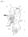
- Fig. 1 is a left side view illustrating a schematic configuration example of an outboard motor 10 according to the present invention.
- the outboard motor 10 is fixed, at its front side, to a rear stern plate P of a hull, as illustrated in the drawing.
- the front of the outboard motor 10 is indicated by an arrow mark Fr
- the rear is indicated by an arrow mark Rr
- the right on the side of the outboard motor 10 is indicated by an arrow mark R and the left on the side is indicated by an arrow mark L, respectively, as necessary in each drawing.
- an engine unit or power unit 11, a middle unit 12, and a lower unit 13 are arranged in order from the top to the bottom.
- an engine 14 is mounted and supported to be vertically placed, through an engine base, so that its crank shaft 15 is oriented in the vertical direction.
- the middle unit 12 is supported around and integrally rotatable with a supporting shaft 19 set on a swivel bracket 18 through an upper mount 16 and a lower mount 17.
- a clamp bracket 20 is provided, and the outboard motor 10 is fixed to the rear stern plate P of the hull through the clamp bracket 20.
- the swivel bracket 18 is supported to be rotatable in the upward and downward directions, around a tilt shaft 21 set in the right and left directions.
- a drive shaft 22 coupled to a lower end portion of the crank shaft 15 is disposed to penetrate in the upward and downward directions, so that a driving force of the drive shaft 22 is transmitted to a later-described propeller shaft in a gear case of the lower unit 13.
- a shift rod 23 for switching between forward and rearward travels and the like is disposed to be parallel to the upward and downward directions.
- the shift rod 23 includes an upper shift rod 30 and a lower shift rod 31.
- the middle unit 12 has a drive shaft housing that houses the drive shaft 22. Further, an oil pan storing oil for lubricating the engine unit 11 is disposed in the middle unit 12.
- the lower unit 13 has a gear case 25 including a plurality of gears and so on which rotationally drive a propeller 24 by the driving force of the drive shaft 22.
- the drive shaft 22 extending downward from the middle unit 12 finally rotates the propeller 24 by a gear attached to the drive shaft 22 meshing with the gear in the gear case 25, and the shift rod 23 operates to switch, namely, shift the power transmission path of the gear device in the gear case 25.
- Fig. 2 to Fig. 6 illustrate a concrete configuration example of the lower unit 13.
- Fig. 2 is a rear perspective view of the lower unit 13
- Fig. 3 is a longitudinal sectional view along an axial direction of propeller of the lower unit 13
- Fig. 4 is an exploded perspective view of a part in the vicinity of a casing of the lower unit 13
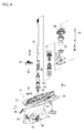
- Fig. 5 and Fig. 6 are views respectively illustrating a main configuration in the gear case 25. Note that in Fig. 5 and Fig. 6 , it is set that components are mutually connected as indicated by a mark First, in a casing 26 which is integrally formed as illustrated in Fig. 2 or Fig.
- an anti-splash plate 27 and an anti-cavitation plate 28 disposed at top and bottom in the vicinity of a mating surface with the middle unit 12, and on a lower part of a leg part 29 extending downward of these plates, there is provided the gear case 25 disposed to exhibit a bullet shape in the forward and rearward directions.
- the shift rod 23 is inserted and supported in the upward and downward directions on a side of a pointed end portion of the bullet shape of the gear case 25 in the casing 26.
- the shift rod 23 is practically configured by being divided into two, which are, the upper shift rod 30 which is extended to a region from the engine unit 11 to the middle unit 12, and the lower shift rod 31 which is disposed in the lower unit 13, as illustrated in Fig. 3 .
- the upper shift rod 30 is rotationally driven via a link mechanism by a driving force of a not-illustrated actuator provided on the engine unit 11 side, and the rotation is further transmitted to the lower shift rod 31 via a coupling gear 34 formed of a pair of drive gear 32 and driven gear 33.
- a coupling portion between the upper shift rod 30 and the lower shift rod 31 is set to be held by a shift rod housing 35 fixed to an upper surface of the casing 26.
- the shift rod 23, namely, the lower shift rod 31 is vertically extended to a position intersecting an extension of an axis of a propeller shaft 36.
- the drive shaft 22 is inserted and supported in the vicinity of substantially a center portion in the forward and rearward directions of the leg part 29 in the casing 26.
- the drive shaft 22 is supported in a rotatable manner in the casing 26 via a back-to-back tapered roller bearing 37, for example, in the vicinity of an upper part of the leg part 29, and a lower end portion thereof is vertically extended to reach the inside of the gear case 25.
- a spiral recessed groove 38 is carved, and a collar 39 is fitted to a periphery of the recessed groove 38 with a very small gap provided between the collar and an outer peripheral surface of the drive shaft 22.
- the spiral recessed groove 38 When the drive shaft 22 is rotated, the spiral recessed groove 38 performs a function of supplying oil or an oil pump function, and forms an oil circulation path for supplying lubricant oil to main parts and members which need to be lubricated in the casing 26. Note that an oil pump for lubrication for the engine unit 11 is arranged separately from one formed of this recessed groove 38.
- a cooling water pump 40 is attached so as to be pivotally fitted to the drive shaft 22.
- the cooling water pump 40 takes in water from water outside the outboard motor 10 to supply cooling water to the engine unit 11 side.
- a water intake 41 is provided in the vicinity of a lower part on the front side of the casing 26 as illustrated in Fig. 4 , and although detailed illustration is omitted, the cooling water pump 40 and the water intake 41 are connected by a cooling water channel in the inside of the casing 26.
- a cover 42 having a filter function with respect to foreign matters and the like is attached to the water intake 41.
- the water intake 41 is disposed between the drive shaft 22 and the lower shift rod 31 in the forward and rearward directions.
- an impeller 43 is fixed to the drive shaft 22, and the impeller 43 is housed in a pump case 44.
- pressurized cooling water is discharged from the cooling water pump 40, and the cooling water is fed via a cooling water pipe 45, and is finally supplied to the engine unit 11 side.
- the propeller shaft 36 is disposed along the forward and rearward directions as illustrated in Fig. 3 , and is supported in a rotatable manner via a plurality of bearings 46, 47 and 48.
- the bearings 47 and 48 are held in a bearing housing 49.
- a pair of front and rear forward gear 50 and reverse gear 51 are supported in a rotatable manner via bearings 52 and 53, respectively, in a concentric state and in a loose-fitted state with respect to the propeller shaft 36.
- These gears constantly mesh with a drive gear 54 fixed to the lower end portion of the drive shaft 22.
- the forward gear 50 and the reverse gear 51 are disposed on the front Fr side and on the rear Rr side, respectively, and a dog clutch 55 is arranged between these gears.
- an exhaust passage 56 which is communicated with an exhaust manifold of the engine 14, as illustrated in Fig. 3 .
- the exhaust passage 56 is formed so that exhaust gas flows from above the bearing housing 49 into a later-described gap of the bearing housing 49, at the rear side of the drive shaft 22.
- a propeller boss 57 of the propeller 24 is formed in a substantially cylindrical shape and practically has a hollow structure, and exhaust gas G passes through the bearing housing 49 from the exhaust passage 56, and passes through the propeller boss 57 to be discharged to the rear of the propeller boss 57, as indicated by arrow marks.
- Figs. 7 illustrate a configuration example of the bearing housing 49.
- the bearing housing 49 generally has a cylindrical body having different diameters in which a diameter changes along an axial direction or a longitudinal direction, and includes a front portion 49a and a rear portion 49b with a large diameter and a cylindrical portion 49c with a small diameter connecting these portions.
- the rear portion 49b and the cylindrical portion 49c are coupled by a plurality of ribs 49d radially projecting from the cylindrical portion 49c.
- These ribs 49d are extended in the axial direction, and a gap or a hollow space is formed between the mutual ribs 49d.
- the gap functions as the above-described exhaust passage 56.
- Fig. 8 illustrates a configuration of substantial part of the exhaust structure of the present invention.
- the propeller boss 57 is pivotally fitted to a rear end portion of the propeller shaft 36 via a propeller bush 58, and is fastened and fixed by a locknut.
- a housing part 59 for housing the bearing housing 49 is provided, and the bearing housing 49 is inserted to be fitted into the housing part 59 from the rear.
- the bearing housing 49 inserted to be fitted into the housing part 59 is fixed by a stopper 60 which is screwed into the rear end portion of the gear case 25.
- an O ring 61 is attached between the bearing housing 49 and the stopper 60.
- Figs. 9 illustrate a configuration example of the stopper 60.
- the stopper 60 generally has a ring shape, and on an outer peripheral portion thereof, there is formed a screw portion 60a (male screw) which is screwed together with a screw portion 25a (female screw) formed on the opening of the rear part of the gear case 25.
- a screw portion 60a male screw
- a screw portion 25a female screw
- Figs. 10 illustrate a configuration example of the propeller boss 57, particularly, a part in the vicinity of a front end portion 57a (M part in Fig. 8 ).
- the propeller boss 57 is formed to have the largest diameter at the front end portion 57a, and an outside diameter of the front end portion 57a is set to D 1 in this case.
- a tip portion 57c is formed in a connected manner via a step portion 57b.
- An outside diameter of the tip portion 57c is smaller than that of the front end portion 57a, and the tip portion 57c is disposed to be inserted into an inner peripheral portion of the stopper 60.
- the stopper 60 is screwed into a base end side of the bullet shape of the gear case 25, namely, the opening of the rear part formed on the rear end portion of the gear case 25, as described above, and the outside diameter D 1 of the front end portion 57a of the propeller boss 57 is set to be larger than an outside diameter D 2 of the base end side.
- the outside diameter D 1 of the front end portion 57a of the propeller boss 57 is set to be larger than an outside diameter D 2 of the base end side.
- the propeller boss 57 is dividedly configured by an inside boss and an outside boss. These inside boss and outside boss are mutually and integrally coupled to function as the propeller boss, and in such a propeller boss, an outside diameter of a front end portion of the outside boss is practically set to be larger than the outside diameter D 2 of the rear end portion of the gear case 25, similar to the above description.
- the step portion 57b that forms an end face of the front end portion 57a of the propeller boss 57 is formed by being inclined toward the gear case 25 side with respect to a radial direction of the propeller boss 57, namely, a direction orthogonal to an axis of rotation of propeller.
- an inclination angle ⁇ of the step portion 57b toward the gear case 25 side is suitably set to 0 ⁇ , as illustrated in Fig. 10B .
- the step portion 57b itself is basically formed of a flat flat surface, but, it is also possible to be formed to have a concave shape toward a forward direction, as indicated by a two-dot chain line in Fig. 10B .
- the exhaust gas passes through the exhaust passage 56 configured by including the gap of the bearing housing 49, and passes through the propeller boss 57 to be discharged to the rear of the propeller boss 57, as described above.
- a region A on a rear surface side thereof basically has a negative pressure (- (minus)), as illustrated in Fig. 11 .
- the outside diameter D 1 of the front end portion 57a is typically larger than the outside diameter D 2 of the rear end portion of the gear case 25, namely, the portion of the step portion 57b further protrudes outward in the radial direction from the rear end portion of the gear case 25.
- the dynamic pressure is generated, and a positive pressure (+ (plus)) is induced in a region B on the front side of the step portion 57b as illustrated in Fig. 11 , resulting in that exhaust gas G can be securely prevented from leaking from the clearance S formed on the region B. Therefore, there is no chance that the leaked exhaust gas is led into the rotating propeller 24, resulting in that a high propulsion efficiency of the propeller 24 can be secured and maintained.
- the step portion 57b that forms the end face of the front end portion 57a of the propeller boss 57 is inclined toward the gear case 25 side, the dynamic pressure is generated, and in addition to that, the water flow is effectively and accurately received by the front end portion 57a.
- the front end portion 57a securely catches the water flow as described above, even if the induced positive pressure fluctuates in some degree, it is possible to constantly secure and maintain the effect of preventing the leakage of exhaust gas G.
- the end face of the front end portion 57a of the propeller boss 57 is suitably inclined toward the gear case 25 side as described above so that it effectively acts to exhibit the effect of preventing the leakage of exhaust gas.
- the inclination angle ⁇ of the end face is set to 0.
- the water flow is received by the protruding portion protruding outward in the radial direction of the front end portion 57a, and accordingly, it is possible to achieve the operation of generating the dynamic pressure.
- the step portion 57b is formed to have a concave shape toward the forward direction as described above (two-dot chain line in Fig. 10B ), it is possible to further facilitate the operation of catching the water flow with the use of the front end portion 57a.
- a ring-shaped member 57A having practically the same size and shape as those of the front end portion 57a of the propeller boss 57 is separately provided, and the ring-shaped member 57A is fixed by being fitted into a portion corresponding to the front end portion 57a of the propeller boss 57.
- a fitting portion 57d is formed on an outer peripheral portion corresponding to the front end portion 57a of the propeller boss 57 (here, referred to as a propeller boss main body), and a fitting hole 57e is formed on the ring-shaped member 57A.
- a tip portion 57C corresponding to the tip portion 57c is formed in a connected manner.
- concrete numerical values of the outside diameter D 1 of the front end portion 57a, the outside diameter D 2 of the rear end portion of the gear case 25, the inclination angle ⁇ of the end face of the front end portion 57a or the like can be appropriately selected according to need.
- the outside diameter of the front end portion of the propeller boss is typically set to be larger than the outside diameter of the rear end portion of the gear case, and the front end portion protrudes outward in a radial direction.
- a flow of water that hits against the protruding portion is received, a dynamic pressure is generated, and a positive pressure is induced in a region on a front side of the front end portion, which enables to securely prevent exhaust gas from leaking from a clearance formed on this region. Accordingly, it is possible to secure and maintain a high propulsion efficiency of the propeller by preventing the leaked exhaust gas from being led into the rotating propeller.
Landscapes
- Chemical & Material Sciences (AREA)
- Engineering & Computer Science (AREA)
- Combustion & Propulsion (AREA)
- Mechanical Engineering (AREA)
- Ocean & Marine Engineering (AREA)
- Exhaust Silencers (AREA)
Abstract
Description
- This application is based upon and claims the benefit of priority of the prior Japanese Patent Application No.
2012-001481, filed on January 6, 2012 - The present invention relates to an exhaust structure for discharging exhaust gas after combustion to the outside in an outboard motor on which an internal combustion engine is mounted as a power source.
- In this type of outboard motor, an engine output torque is transmitted from a drive shaft to a propeller shaft, and a propeller disposed at a rear part of the outboard motor is rotated, to thereby obtain a thrust. The propeller has a cylindrical boss, and is attached to the propeller shaft with this boss portion. Exhaust gas from an engine passes through the boss to be discharged into water.
- Generally, a gap between an outside diameter of a front end portion of a propeller boss and an inside diameter of a rear end portion of a gear case cannot be set to a value equal to or less than a certain value for avoiding a contact due to a swing of the propeller. In this case, there is a possibility that exhaust gas passing through an inside of the propeller boss is leaked from the gap. When the leaked exhaust gas is led into the propeller, and if this state continues, a propulsion efficiency of the propeller is decreased.
- Accordingly, an outboard motor disclosed in Patent Document 1, for example, employs a structure in which a rear end portion of a gear case or a cover of the gear case is protruded so that an inner periphery and an outer periphery of a front end portion of a propeller boss are overlapped. With such a structure, a leakage of exhaust gas is prevented.
- Patent Document 1: Japanese Utility Model Application Publication No.
55-085999 - In the outboard motor disclosed in Patent Document 1, although a labyrinth structure is formed between the front end portion of the propeller boss and the rear end portion of the gear case, even in this case, there is required a gap, to no small extent, to prevent a contact between the both due to a swing of a propeller shaft. Accordingly, it was not always possible to achieve a sufficient effect of preventing a leakage of exhaust gas.
- The present invention has been made in view of such a situation, and an object thereof is to provide an exhaust structure of an outboard motor providing an excellent effect of preventing a leakage of exhaust gas and improving and maintaining an exhaust performance.
- An exhaust structure of an outboard motor of the present invention being an exhaust structure of an outboard motor in which exhaust gas from an engine is designed to pass through a lower unit, and pass through a propeller boss coupled to a propeller shaft to be discharged into water, the exhaust structure of the outboard motor is characterized in that it includes a front end portion of the propeller boss whose outside diameter is set to be equal to or larger than an outside diameter of a rear end portion of a gear case in the lower unit.
- Further, the exhaust structure of the outboard motor of the present invention is characterized in that an end face of the front end portion of the propeller boss is formed by being inclined toward the rear end portion side of the gear case with respect to a direction orthogonal to an axis of rotation of propeller, or formed along the direction orthogonal to the axis.
- Further, the exhaust structure of the outboard motor of the present invention is characterized in that the propeller boss is formed of an inside boss and an outside boss, and an outside diameter of a front end portion of the outside boss is set to be larger than the outside diameter of the rear end portion of the gear case.
- Further, the exhaust structure of the outboard motor of the present invention is characterized in that the front end portion of the propeller boss is formed separately from a propeller boss main body, and is fixed by being fitted into a predetermined portion of the propeller boss main body.
-
-
Fig. 1 is a left side view illustrating a schematic configuration example of an outboard motor according to the present invention; -
Fig. 2 is a rear perspective view of a lower unit of the outboard motor according to the present invention; -
Fig. 3 is a longitudinal sectional view along an axial direction of propeller of the lower unit of the outboard motor according to the present invention; -
Fig. 4 is an exploded perspective view of a part in the vicinity of a casing of the lower unit in the outboard motor according to the present invention; -
Fig. 5 is an exploded perspective view illustrating a main configuration in a gear case of the outboard motor according to the present invention; -
Fig. 6 is an exploded perspective view illustrating a main configuration in the gear case of the outboard motor according to the present invention; -
Fig. 7A is a front perspective view, andFig. 7B is a rear perspective view illustrating a configuration example of a bearing housing according to the present invention; -
Fig. 8 is a sectional view of a part in the vicinity of a propeller boss illustrating a configuration of substantial part in an exhaust structure of the outboard motor according to the present invention; -
Fig. 9A is a front view illustrating a configuration example of a stopper according to the present invention, andFig. 9B is a sectional view taken along a II-II line inFig. 9A ; -
Figs. 10A and 10B are respectively enlarged views of M part inFig. 8 , illustrating a configuration example of a part in the vicinity of a front end portion of the propeller boss according to the present invention; -
Fig. 11 is an enlarged view of a part in the vicinity of the front end portion of the propeller boss, illustrating an operation of the present invention; and -
Figs. 12A and 12B are respectively side views illustrating a modified example of the propeller boss according to the present invention. - Hereinafter, a preferred embodiment of an exhaust structure of an outboard motor according to the present invention will be described based on the drawings.
-
Fig. 1 is a left side view illustrating a schematic configuration example of anoutboard motor 10 according to the present invention. In this case, theoutboard motor 10 is fixed, at its front side, to a rear stern plate P of a hull, as illustrated in the drawing. Note that in the following description, the front of theoutboard motor 10 is indicated by an arrow mark Fr, the rear is indicated by an arrow mark Rr, and the right on the side of theoutboard motor 10 is indicated by an arrow mark R and the left on the side is indicated by an arrow mark L, respectively, as necessary in each drawing. - In the whole configuration of the
outboard motor 10, an engine unit orpower unit 11, amiddle unit 12, and alower unit 13 are arranged in order from the top to the bottom. In theengine unit 11, anengine 14 is mounted and supported to be vertically placed, through an engine base, so that itscrank shaft 15 is oriented in the vertical direction. Note that, as theengine 14, a V-type multicylinder engine can be employed, for example. Themiddle unit 12 is supported around and integrally rotatable with a supportingshaft 19 set on aswivel bracket 18 through anupper mount 16 and alower mount 17. On both right and left sides of theswivel bracket 18, aclamp bracket 20 is provided, and theoutboard motor 10 is fixed to the rear stern plate P of the hull through theclamp bracket 20. Theswivel bracket 18 is supported to be rotatable in the upward and downward directions, around atilt shaft 21 set in the right and left directions. - In the
middle unit 12, adrive shaft 22 coupled to a lower end portion of thecrank shaft 15 is disposed to penetrate in the upward and downward directions, so that a driving force of thedrive shaft 22 is transmitted to a later-described propeller shaft in a gear case of thelower unit 13. On the front side of thedrive shaft 22, ashift rod 23 for switching between forward and rearward travels and the like is disposed to be parallel to the upward and downward directions. Theshift rod 23 includes anupper shift rod 30 and alower shift rod 31. Note that themiddle unit 12 has a drive shaft housing that houses thedrive shaft 22. Further, an oil pan storing oil for lubricating theengine unit 11 is disposed in themiddle unit 12. - The
lower unit 13 has agear case 25 including a plurality of gears and so on which rotationally drive apropeller 24 by the driving force of thedrive shaft 22. Thedrive shaft 22 extending downward from themiddle unit 12 finally rotates thepropeller 24 by a gear attached to thedrive shaft 22 meshing with the gear in thegear case 25, and theshift rod 23 operates to switch, namely, shift the power transmission path of the gear device in thegear case 25. -
Fig. 2 to Fig. 6 illustrate a concrete configuration example of thelower unit 13.Fig. 2 is a rear perspective view of thelower unit 13,Fig. 3 is a longitudinal sectional view along an axial direction of propeller of thelower unit 13,Fig. 4 is an exploded perspective view of a part in the vicinity of a casing of thelower unit 13, andFig. 5 andFig. 6 are views respectively illustrating a main configuration in thegear case 25. Note that inFig. 5 andFig. 6 , it is set that components are mutually connected as indicated by a markFirst, in a
casing 26 which is integrally formed as illustrated inFig. 2 orFig. 4 , there are provided ananti-splash plate 27 and ananti-cavitation plate 28 disposed at top and bottom in the vicinity of a mating surface with themiddle unit 12, and on a lower part of aleg part 29 extending downward of these plates, there is provided thegear case 25 disposed to exhibit a bullet shape in the forward and rearward directions. - The
shift rod 23 is inserted and supported in the upward and downward directions on a side of a pointed end portion of the bullet shape of thegear case 25 in thecasing 26. Note that theshift rod 23 is practically configured by being divided into two, which are, theupper shift rod 30 which is extended to a region from theengine unit 11 to themiddle unit 12, and thelower shift rod 31 which is disposed in thelower unit 13, as illustrated inFig. 3 . Note that theupper shift rod 30 is rotationally driven via a link mechanism by a driving force of a not-illustrated actuator provided on theengine unit 11 side, and the rotation is further transmitted to thelower shift rod 31 via acoupling gear 34 formed of a pair of drive gear 32 and driven gear 33. A coupling portion between theupper shift rod 30 and thelower shift rod 31 is set to be held by ashift rod housing 35 fixed to an upper surface of thecasing 26. As illustrated inFig. 3 , theshift rod 23, namely, thelower shift rod 31 is vertically extended to a position intersecting an extension of an axis of apropeller shaft 36. - Further, as illustrated in
Fig. 3 , thedrive shaft 22 is inserted and supported in the vicinity of substantially a center portion in the forward and rearward directions of theleg part 29 in thecasing 26. In this case, thedrive shaft 22 is supported in a rotatable manner in thecasing 26 via a back-to-back taperedroller bearing 37, for example, in the vicinity of an upper part of theleg part 29, and a lower end portion thereof is vertically extended to reach the inside of thegear case 25. On a part below the taperedroller bearing 37 of thedrive shaft 22, a spiral recessedgroove 38 is carved, and acollar 39 is fitted to a periphery of the recessedgroove 38 with a very small gap provided between the collar and an outer peripheral surface of thedrive shaft 22. - When the
drive shaft 22 is rotated, the spiral recessedgroove 38 performs a function of supplying oil or an oil pump function, and forms an oil circulation path for supplying lubricant oil to main parts and members which need to be lubricated in thecasing 26. Note that an oil pump for lubrication for theengine unit 11 is arranged separately from one formed of this recessedgroove 38. - On the upper surface of the
casing 26, a coolingwater pump 40 is attached so as to be pivotally fitted to thedrive shaft 22. The coolingwater pump 40 takes in water from water outside theoutboard motor 10 to supply cooling water to theengine unit 11 side. In this case, awater intake 41 is provided in the vicinity of a lower part on the front side of thecasing 26 as illustrated inFig. 4 , and although detailed illustration is omitted, the coolingwater pump 40 and thewater intake 41 are connected by a cooling water channel in the inside of thecasing 26. Note that to thewater intake 41, acover 42 having a filter function with respect to foreign matters and the like is attached. As illustrated inFig. 3 , thewater intake 41 is disposed between thedrive shaft 22 and thelower shift rod 31 in the forward and rearward directions. - As illustrated in
Fig. 3 andFig. 4 , in the coolingwater pump 40, animpeller 43 is fixed to thedrive shaft 22, and theimpeller 43 is housed in apump case 44. When thedrive shaft 22 is rotated, pressurized cooling water is discharged from the coolingwater pump 40, and the cooling water is fed via a coolingwater pipe 45, and is finally supplied to theengine unit 11 side. - In the
gear case 25, thepropeller shaft 36 is disposed along the forward and rearward directions as illustrated inFig. 3 , and is supported in a rotatable manner via a plurality ofbearings bearings housing 49. At a position below a lower end portion of thedrive shaft 22, a pair of front andrear forward gear 50 andreverse gear 51 are supported in a rotatable manner viabearings propeller shaft 36. These gears constantly mesh with adrive gear 54 fixed to the lower end portion of thedrive shaft 22. In this example, theforward gear 50 and thereverse gear 51 are disposed on the front Fr side and on the rear Rr side, respectively, and adog clutch 55 is arranged between these gears. - In the above-described configuration, when the hull is made to travel forward, for example, there is formed a power transmission path from the
forward gear 50 to thepropeller shaft 36 via thedog clutch 55, through a shift operation. When theengine 14 is started, an output torque thereof is transmitted to thedrive shaft 22, and thepropeller shaft 36 is rotated via theforward gear 50, which rotates thepropeller 24, resulting in that theoutboard motor 10, namely, the hull on which theoutboard motor 10 is mounted, travels forward. It is designed such that exhaust gas discharged from theengine 14 at this time passes through the inside of theoutboard motor 10, and is finally discharged from a part of thepropeller 24. - Specifically, there is formed, from the
middle unit 12 to thelower unit 13, anexhaust passage 56 which is communicated with an exhaust manifold of theengine 14, as illustrated inFig. 3 . Theexhaust passage 56 is formed so that exhaust gas flows from above the bearinghousing 49 into a later-described gap of the bearinghousing 49, at the rear side of thedrive shaft 22. In this case, apropeller boss 57 of thepropeller 24 is formed in a substantially cylindrical shape and practically has a hollow structure, and exhaust gas G passes through the bearinghousing 49 from theexhaust passage 56, and passes through thepropeller boss 57 to be discharged to the rear of thepropeller boss 57, as indicated by arrow marks. - Here,
Figs. 7 illustrate a configuration example of the bearinghousing 49. The bearinghousing 49 generally has a cylindrical body having different diameters in which a diameter changes along an axial direction or a longitudinal direction, and includes afront portion 49a and arear portion 49b with a large diameter and acylindrical portion 49c with a small diameter connecting these portions. Therear portion 49b and thecylindrical portion 49c are coupled by a plurality ofribs 49d radially projecting from thecylindrical portion 49c. Theseribs 49d are extended in the axial direction, and a gap or a hollow space is formed between themutual ribs 49d. The gap functions as the above-describedexhaust passage 56. Note that to thefront portion 49a, thebearing 53 and thebearing 47 are attached, and further, to thecylindrical portion 49c, thebearing 48 is attached. Note that in relation toFigs. 7 , the bearinghousing 49 inFig. 3 is illustrated by a cross section taken along a I-I line inFig. 7B . The same applies toFig. 8 and the like. - Next,
Fig. 8 illustrates a configuration of substantial part of the exhaust structure of the present invention. Thepropeller boss 57 is pivotally fitted to a rear end portion of thepropeller shaft 36 via apropeller bush 58, and is fastened and fixed by a locknut. On an opening side of the rear part of the gear case 25 (casing 26) in which thepropeller shaft 36 is inserted to be disposed, ahousing part 59 for housing the bearinghousing 49 is provided, and the bearinghousing 49 is inserted to be fitted into thehousing part 59 from the rear. The bearinghousing 49 inserted to be fitted into thehousing part 59 is fixed by astopper 60 which is screwed into the rear end portion of thegear case 25. Note that anO ring 61 is attached between the bearinghousing 49 and thestopper 60. - Here,
Figs. 9 illustrate a configuration example of thestopper 60. Thestopper 60 generally has a ring shape, and on an outer peripheral portion thereof, there is formed ascrew portion 60a (male screw) which is screwed together with ascrew portion 25a (female screw) formed on the opening of the rear part of thegear case 25. When thestopper 60 is screwed into the opening of the rear part of thegear case 25 as illustrated inFig. 8 , rear ends of the both are aligned so that both ends become practically flush with each other. - Further,
Figs. 10 illustrate a configuration example of thepropeller boss 57, particularly, a part in the vicinity of afront end portion 57a (M part inFig. 8 ). As illustrated inFig. 10A , thepropeller boss 57 is formed to have the largest diameter at thefront end portion 57a, and an outside diameter of thefront end portion 57a is set to D1 in this case. Further, on a front side of thefront end portion 57a, atip portion 57c is formed in a connected manner via astep portion 57b. An outside diameter of thetip portion 57c is smaller than that of thefront end portion 57a, and thetip portion 57c is disposed to be inserted into an inner peripheral portion of thestopper 60. Meanwhile, thestopper 60 is screwed into a base end side of the bullet shape of thegear case 25, namely, the opening of the rear part formed on the rear end portion of thegear case 25, as described above, and the outside diameter D1 of thefront end portion 57a of thepropeller boss 57 is set to be larger than an outside diameter D2 of the base end side. Note that as illustrated inFig. 10A , there is formed an appropriate gap or clearance S between a portion from thestep portion 57b adjacent to thefront end portion 57a to thetip portion 57c and the base end side of the bullet shape of thegear case 25 and thestopper 60 screwed into the base end side. - Here, although the illustration is omitted, there is a case that the
propeller boss 57 is dividedly configured by an inside boss and an outside boss. These inside boss and outside boss are mutually and integrally coupled to function as the propeller boss, and in such a propeller boss, an outside diameter of a front end portion of the outside boss is practically set to be larger than the outside diameter D2 of the rear end portion of thegear case 25, similar to the above description. - Further, the
step portion 57b that forms an end face of thefront end portion 57a of thepropeller boss 57 is formed by being inclined toward thegear case 25 side with respect to a radial direction of thepropeller boss 57, namely, a direction orthogonal to an axis of rotation of propeller. In this case, an inclination angle θ of thestep portion 57b toward thegear case 25 side is suitably set to 0<θ, as illustrated inFig. 10B . Note that it is also possible to set that θ=0, and also in that case, a certain effect can be achieved. Further, thestep portion 57b itself is basically formed of a flat flat surface, but, it is also possible to be formed to have a concave shape toward a forward direction, as indicated by a two-dot chain line inFig. 10B . - When the
engine 14 is started in the above-described configuration, the exhaust gas passes through theexhaust passage 56 configured by including the gap of the bearinghousing 49, and passes through thepropeller boss 57 to be discharged to the rear of thepropeller boss 57, as described above. In this case, when thepropeller 24 rotates, a region A on a rear surface side thereof basically has a negative pressure (- (minus)), as illustrated inFig. 11 . Meanwhile, in thepropeller boss 57, particularly, the part in the vicinity of thefront end portion 57a, the outside diameter D1 of thefront end portion 57a is typically larger than the outside diameter D2 of the rear end portion of thegear case 25, namely, the portion of thestep portion 57b further protrudes outward in the radial direction from the rear end portion of thegear case 25. When the flow of water that hits against the protruding portion is received, the dynamic pressure is generated, and a positive pressure (+ (plus)) is induced in a region B on the front side of thestep portion 57b as illustrated inFig. 11 , resulting in that exhaust gas G can be securely prevented from leaking from the clearance S formed on the region B. Therefore, there is no chance that the leaked exhaust gas is led into the rotatingpropeller 24, resulting in that a high propulsion efficiency of thepropeller 24 can be secured and maintained. - Note that generally, in this type of outboard motor, it is often the case that the diameter of the front end portion of the propeller boss is smaller than that of the rear end portion of the gear case (the one disclosed in Cited Document 1, for example), and in such a case, exhaust gas is easily leaked from a clearance between those portions. In the present embodiment, the example in which the outside diameter D1 is larger than the outside diameter D2 is explained in the above-described explanation, but, by at least setting that D1=D2, it is possible to achieve a certain effect of preventing the leakage of exhaust gas G, compared to a case where the diameter of the front end portion of the propeller boss is smaller than that of the rear end portion of the gear case.
- Further, in the above-described case, since the
step portion 57b that forms the end face of thefront end portion 57a of thepropeller boss 57 is inclined toward thegear case 25 side, the dynamic pressure is generated, and in addition to that, the water flow is effectively and accurately received by thefront end portion 57a. Specifically, when thefront end portion 57a securely catches the water flow as described above, even if the induced positive pressure fluctuates in some degree, it is possible to constantly secure and maintain the effect of preventing the leakage of exhaust gas G. Together with the operation of inducing the positive pressure in the region B described above, it is possible to largely improve the propulsion performance of thepropeller 24 by constantly maintaining a pressure distribution as inFig. 11 when theoutboard motor 10 travels. - The end face of the
front end portion 57a of thepropeller boss 57 is suitably inclined toward thegear case 25 side as described above so that it effectively acts to exhibit the effect of preventing the leakage of exhaust gas. In this case, by at least setting the inclination angle θ of the end face to 0, the water flow is received by the protruding portion protruding outward in the radial direction of thefront end portion 57a, and accordingly, it is possible to achieve the operation of generating the dynamic pressure. Further, when thestep portion 57b is formed to have a concave shape toward the forward direction as described above (two-dot chain line inFig. 10B ), it is possible to further facilitate the operation of catching the water flow with the use of thefront end portion 57a. - Note that when the
propeller 24 is rotated, there is a chance that a swing of shaft of thepropeller 24, namely, a swing of thepropeller shaft 36 occurs due to an influence of variation in an applied load with respect to thepropeller 24 and the like. Even when such a swing of shaft occurs, since the clearance S is provided between thegear case 25 side and thepropeller boss 57 side, it is possible to effectively deal with such a swing of shaft. In addition to that, it is possible to secure and maintain a high propulsion efficiency of thepropeller 24 as described above. - Here, a modified example of the present invention will be described. In this example, as illustrated in
Figs. 12 , a ring-shapedmember 57A having practically the same size and shape as those of thefront end portion 57a of thepropeller boss 57 is separately provided, and the ring-shapedmember 57A is fixed by being fitted into a portion corresponding to thefront end portion 57a of thepropeller boss 57. More concretely, as illustrated inFig. 12A , afitting portion 57d is formed on an outer peripheral portion corresponding to thefront end portion 57a of the propeller boss 57 (here, referred to as a propeller boss main body), and afitting hole 57e is formed on the ring-shapedmember 57A. On the front side of thefitting portion 57d, atip portion 57C corresponding to thetip portion 57c is formed in a connected manner. - When the
fitting portion 57d of thepropeller boss 57 and thefitting hole 57e of the ring-shapedmember 57A are fitted into each other, there is formed afront end portion 57a having practically the same outside diameter D1 and inclination angle θ as those of thefront end portion 57a of the aforementioned embodiment in thepropeller boss 57, as illustrated inFig. 12B . Particularly, in this example, it becomes possible to largely reduce a material, a man-hour or the like, compared to a case where a portion on the rear side of thefront end portion 57a is formed through cutting, for example, and the like. - The present invention has been described above together with various embodiments, but, the present invention is not limited to these embodiments, and modifications and the like can be made within the scope of the present invention.
- For example, concrete numerical values of the outside diameter D1 of the
front end portion 57a, the outside diameter D2 of the rear end portion of thegear case 25, the inclination angle θ of the end face of thefront end portion 57a or the like can be appropriately selected according to need. - According to the present invention, the outside diameter of the front end portion of the propeller boss is typically set to be larger than the outside diameter of the rear end portion of the gear case, and the front end portion protrudes outward in a radial direction. A flow of water that hits against the protruding portion is received, a dynamic pressure is generated, and a positive pressure is induced in a region on a front side of the front end portion, which enables to securely prevent exhaust gas from leaking from a clearance formed on this region. Accordingly, it is possible to secure and maintain a high propulsion efficiency of the propeller by preventing the leaked exhaust gas from being led into the rotating propeller.
- It should be noted that the above embodiments merely illustrate concrete examples of implementing the present invention, and the technical scope of the present invention is not to be construed in a restrictive manner by these embodiments. That is, the present invention may be implemented in various forms without departing from the technical spirit or main features thereof.
Claims (8)
- An exhaust structure of an outboard motor in which exhaust gas from an engine is designed to pass through a lower unit, and pass through a propeller boss coupled to a propeller shaft to be discharged into water, the exhaust structure of the outboard motor comprising
a front end portion of the propeller boss whose outside diameter is set to be equal to or larger than an outside diameter of a rear end portion of a gear case in the lower unit. - The exhaust structure of the outboard motor according to claim 1, wherein
an end face of said front end portion of the propeller boss is formed by being inclined toward the rear end portion side of the gear case with respect to a direction orthogonal to an axis of rotation of propeller, or formed along the direction orthogonal to the axis. - The exhaust structure of the outboard motor according to claim 1, wherein
the propeller boss is formed of an inside boss and an outside boss, and an outside diameter of a front end portion of the outside boss is set to be larger than the outside diameter of the rear end portion of the gear case. - The exhaust structure of the outboard motor according to claim 2, wherein
the propeller boss is formed of an inside boss and an outside boss, and an outside diameter of a front end portion of the outside boss is set to be larger than the outside diameter of the rear end portion of the gear case. - The exhaust structure of the outboard motor according to claim 1, wherein
said front end portion of the propeller boss is formed separately from a propeller boss main body, and is fixed by being fitted into a predetermined portion of the propeller boss main body. - The exhaust structure of the outboard motor according to claim 2, wherein
said front end portion of the propeller boss is formed separately from a propeller boss main body, and is fixed by being fitted into a predetermined portion of the propeller boss main body. - The exhaust structure of the outboard motor according to claim 3, wherein
said front end portion of the propeller boss is formed separately from a propeller boss main body, and is fixed by being fitted into a predetermined portion of the propeller boss main body. - The exhaust structure of the outboard motor according to claim 4, wherein
said front end portion of the propeller boss is formed separately from a propeller boss main body, and is fixed by being fitted into a predetermined portion of the propeller boss main body.
Applications Claiming Priority (1)
| Application Number | Priority Date | Filing Date | Title |
|---|---|---|---|
| JP2012001481A JP2013141835A (en) | 2012-01-06 | 2012-01-06 | Exhaust structure for outboard motor |
Publications (2)
| Publication Number | Publication Date |
|---|---|
| EP2612810A1 true EP2612810A1 (en) | 2013-07-10 |
| EP2612810B1 EP2612810B1 (en) | 2015-11-04 |
Family
ID=47665875
Family Applications (1)
| Application Number | Title | Priority Date | Filing Date |
|---|---|---|---|
| EP13150013.4A Active EP2612810B1 (en) | 2012-01-06 | 2013-01-02 | Exhaust structure of outboard motor |
Country Status (3)
| Country | Link |
|---|---|
| US (1) | US9174716B2 (en) |
| EP (1) | EP2612810B1 (en) |
| JP (1) | JP2013141835A (en) |
Families Citing this family (1)
| Publication number | Priority date | Publication date | Assignee | Title |
|---|---|---|---|---|
| JP2015086974A (en) * | 2013-10-31 | 2015-05-07 | ヤマハ発動機株式会社 | Thermostat, water cooling device, water cooling engine and outboard motor |
Citations (4)
| Publication number | Priority date | Publication date | Assignee | Title |
|---|---|---|---|---|
| US2948252A (en) * | 1957-10-31 | 1960-08-09 | Kiekhaefer Corp | Propeller hub exhaust system |
| US3102506A (en) * | 1962-02-27 | 1963-09-03 | Kiekhaefer Corp | Outboard motor propeller construction |
| JPS5585999U (en) | 1978-12-12 | 1980-06-13 | ||
| US4447214A (en) * | 1982-02-11 | 1984-05-08 | Outboard Marine Corporation | Anti-ventilation means for marine gear case |
Family Cites Families (2)
| Publication number | Priority date | Publication date | Assignee | Title |
|---|---|---|---|---|
| US4778419A (en) * | 1985-04-08 | 1988-10-18 | Outboard Marine Corporation | Reverse thrust propeller |
| JP3537548B2 (en) * | 1995-07-20 | 2004-06-14 | ヤマハマリン株式会社 | Outboard exhaust system |
-
2012
- 2012-01-06 JP JP2012001481A patent/JP2013141835A/en active Pending
-
2013
- 2013-01-02 EP EP13150013.4A patent/EP2612810B1/en active Active
- 2013-01-03 US US13/733,587 patent/US9174716B2/en active Active
Patent Citations (4)
| Publication number | Priority date | Publication date | Assignee | Title |
|---|---|---|---|---|
| US2948252A (en) * | 1957-10-31 | 1960-08-09 | Kiekhaefer Corp | Propeller hub exhaust system |
| US3102506A (en) * | 1962-02-27 | 1963-09-03 | Kiekhaefer Corp | Outboard motor propeller construction |
| JPS5585999U (en) | 1978-12-12 | 1980-06-13 | ||
| US4447214A (en) * | 1982-02-11 | 1984-05-08 | Outboard Marine Corporation | Anti-ventilation means for marine gear case |
Also Published As
| Publication number | Publication date |
|---|---|
| US9174716B2 (en) | 2015-11-03 |
| EP2612810B1 (en) | 2015-11-04 |
| JP2013141835A (en) | 2013-07-22 |
| US20130178121A1 (en) | 2013-07-11 |
Similar Documents
| Publication | Publication Date | Title |
|---|---|---|
| US8641463B2 (en) | Contra-rotating propeller marine propulsion device | |
| US8585366B2 (en) | Contra-rotating propeller marine propulsion device | |
| US7458369B2 (en) | Supercharger lubrication structure | |
| US9481437B2 (en) | Outboard motor | |
| US20080017451A1 (en) | Lubricating structure for marine drive | |
| US9731803B2 (en) | Outboard motor | |
| TWI321622B (en) | Outboard engine system | |
| EP2612810B1 (en) | Exhaust structure of outboard motor | |
| US9022823B2 (en) | Exhaust structure of outboard motor | |
| US5558498A (en) | Propeller shaft assembly for marine propulsion system | |
| KR101914682B1 (en) | Floating bush bearing and ship exhaust turbine | |
| CN203358859U (en) | 60-horsepower ship outboard machine | |
| JP2009097350A (en) | Engine | |
| US9708044B2 (en) | Outboard motor | |
| US20060054146A1 (en) | Supercharger lubrication structure | |
| JP2002234493A (en) | Sealing device for pod propeller propulsion system | |
| US10207781B2 (en) | Propeller unit of marine propulsion apparatus | |
| JP6260425B2 (en) | Outboard motor | |
| US12403999B2 (en) | Marine propulsion system supported by a strut | |
| CN203358858U (en) | 40-horsepower electro-jetting outboard machine | |
| JP6287521B2 (en) | Outboard motor | |
| JP2013015021A (en) | Structure of lubricating device for internal combustion engine | |
| US869887A (en) | Internal-cobustion engine. | |
| JP2022141128A (en) | Strut rolling mechanism of hydrofoil vessel | |
| JP2009121556A (en) | Lubricant oil feeding device to power transfer shaft in transmission case |
Legal Events
| Date | Code | Title | Description |
|---|---|---|---|
| PUAI | Public reference made under article 153(3) epc to a published international application that has entered the european phase |
Free format text: ORIGINAL CODE: 0009012 |
|
| AK | Designated contracting states |
Kind code of ref document: A1 Designated state(s): AL AT BE BG CH CY CZ DE DK EE ES FI FR GB GR HR HU IE IS IT LI LT LU LV MC MK MT NL NO PL PT RO RS SE SI SK SM TR |
|
| AX | Request for extension of the european patent |
Extension state: BA ME |
|
| 17P | Request for examination filed |
Effective date: 20131002 |
|
| RBV | Designated contracting states (corrected) |
Designated state(s): AL AT BE BG CH CY CZ DE DK EE ES FI FR GB GR HR HU IE IS IT LI LT LU LV MC MK MT NL NO PL PT RO RS SE SI SK SM TR |
|
| 17Q | First examination report despatched |
Effective date: 20140708 |
|
| GRAP | Despatch of communication of intention to grant a patent |
Free format text: ORIGINAL CODE: EPIDOSNIGR1 |
|
| INTG | Intention to grant announced |
Effective date: 20150518 |
|
| GRAS | Grant fee paid |
Free format text: ORIGINAL CODE: EPIDOSNIGR3 |
|
| GRAA | (expected) grant |
Free format text: ORIGINAL CODE: 0009210 |
|
| AK | Designated contracting states |
Kind code of ref document: B1 Designated state(s): AL AT BE BG CH CY CZ DE DK EE ES FI FR GB GR HR HU IE IS IT LI LT LU LV MC MK MT NL NO PL PT RO RS SE SI SK SM TR |
|
| REG | Reference to a national code |
Ref country code: GB Ref legal event code: FG4D |
|
| REG | Reference to a national code |
Ref country code: CH Ref legal event code: EP |
|
| REG | Reference to a national code |
Ref country code: AT Ref legal event code: REF Ref document number: 758985 Country of ref document: AT Kind code of ref document: T Effective date: 20151115 |
|
| REG | Reference to a national code |
Ref country code: IE Ref legal event code: FG4D |
|
| REG | Reference to a national code |
Ref country code: DE Ref legal event code: R096 Ref document number: 602013003684 Country of ref document: DE |
|
| REG | Reference to a national code |
Ref country code: NL Ref legal event code: MP Effective date: 20151104 |
|
| REG | Reference to a national code |
Ref country code: LT Ref legal event code: MG4D |
|
| REG | Reference to a national code |
Ref country code: AT Ref legal event code: MK05 Ref document number: 758985 Country of ref document: AT Kind code of ref document: T Effective date: 20151104 |
|
| PG25 | Lapsed in a contracting state [announced via postgrant information from national office to epo] |
Ref country code: HR Free format text: LAPSE BECAUSE OF FAILURE TO SUBMIT A TRANSLATION OF THE DESCRIPTION OR TO PAY THE FEE WITHIN THE PRESCRIBED TIME-LIMIT Effective date: 20151104 Ref country code: NL Free format text: LAPSE BECAUSE OF FAILURE TO SUBMIT A TRANSLATION OF THE DESCRIPTION OR TO PAY THE FEE WITHIN THE PRESCRIBED TIME-LIMIT Effective date: 20151104 Ref country code: IS Free format text: LAPSE BECAUSE OF FAILURE TO SUBMIT A TRANSLATION OF THE DESCRIPTION OR TO PAY THE FEE WITHIN THE PRESCRIBED TIME-LIMIT Effective date: 20160304 Ref country code: LT Free format text: LAPSE BECAUSE OF FAILURE TO SUBMIT A TRANSLATION OF THE DESCRIPTION OR TO PAY THE FEE WITHIN THE PRESCRIBED TIME-LIMIT Effective date: 20151104 Ref country code: NO Free format text: LAPSE BECAUSE OF FAILURE TO SUBMIT A TRANSLATION OF THE DESCRIPTION OR TO PAY THE FEE WITHIN THE PRESCRIBED TIME-LIMIT Effective date: 20160204 Ref country code: ES Free format text: LAPSE BECAUSE OF FAILURE TO SUBMIT A TRANSLATION OF THE DESCRIPTION OR TO PAY THE FEE WITHIN THE PRESCRIBED TIME-LIMIT Effective date: 20151104 |
|
| PG25 | Lapsed in a contracting state [announced via postgrant information from national office to epo] |
Ref country code: GR Free format text: LAPSE BECAUSE OF FAILURE TO SUBMIT A TRANSLATION OF THE DESCRIPTION OR TO PAY THE FEE WITHIN THE PRESCRIBED TIME-LIMIT Effective date: 20160205 Ref country code: LV Free format text: LAPSE BECAUSE OF FAILURE TO SUBMIT A TRANSLATION OF THE DESCRIPTION OR TO PAY THE FEE WITHIN THE PRESCRIBED TIME-LIMIT Effective date: 20151104 Ref country code: PL Free format text: LAPSE BECAUSE OF FAILURE TO SUBMIT A TRANSLATION OF THE DESCRIPTION OR TO PAY THE FEE WITHIN THE PRESCRIBED TIME-LIMIT Effective date: 20151104 Ref country code: PT Free format text: LAPSE BECAUSE OF FAILURE TO SUBMIT A TRANSLATION OF THE DESCRIPTION OR TO PAY THE FEE WITHIN THE PRESCRIBED TIME-LIMIT Effective date: 20160304 Ref country code: RS Free format text: LAPSE BECAUSE OF FAILURE TO SUBMIT A TRANSLATION OF THE DESCRIPTION OR TO PAY THE FEE WITHIN THE PRESCRIBED TIME-LIMIT Effective date: 20151104 Ref country code: AT Free format text: LAPSE BECAUSE OF FAILURE TO SUBMIT A TRANSLATION OF THE DESCRIPTION OR TO PAY THE FEE WITHIN THE PRESCRIBED TIME-LIMIT Effective date: 20151104 Ref country code: SE Free format text: LAPSE BECAUSE OF FAILURE TO SUBMIT A TRANSLATION OF THE DESCRIPTION OR TO PAY THE FEE WITHIN THE PRESCRIBED TIME-LIMIT Effective date: 20151104 Ref country code: FI Free format text: LAPSE BECAUSE OF FAILURE TO SUBMIT A TRANSLATION OF THE DESCRIPTION OR TO PAY THE FEE WITHIN THE PRESCRIBED TIME-LIMIT Effective date: 20151104 Ref country code: BE Free format text: LAPSE BECAUSE OF NON-PAYMENT OF DUE FEES Effective date: 20160131 |
|
| PG25 | Lapsed in a contracting state [announced via postgrant information from national office to epo] |
Ref country code: CZ Free format text: LAPSE BECAUSE OF FAILURE TO SUBMIT A TRANSLATION OF THE DESCRIPTION OR TO PAY THE FEE WITHIN THE PRESCRIBED TIME-LIMIT Effective date: 20151104 |
|
| REG | Reference to a national code |
Ref country code: DE Ref legal event code: R119 Ref document number: 602013003684 Country of ref document: DE |
|
| PG25 | Lapsed in a contracting state [announced via postgrant information from national office to epo] |
Ref country code: SK Free format text: LAPSE BECAUSE OF FAILURE TO SUBMIT A TRANSLATION OF THE DESCRIPTION OR TO PAY THE FEE WITHIN THE PRESCRIBED TIME-LIMIT Effective date: 20151104 Ref country code: DK Free format text: LAPSE BECAUSE OF FAILURE TO SUBMIT A TRANSLATION OF THE DESCRIPTION OR TO PAY THE FEE WITHIN THE PRESCRIBED TIME-LIMIT Effective date: 20151104 Ref country code: EE Free format text: LAPSE BECAUSE OF FAILURE TO SUBMIT A TRANSLATION OF THE DESCRIPTION OR TO PAY THE FEE WITHIN THE PRESCRIBED TIME-LIMIT Effective date: 20151104 Ref country code: SM Free format text: LAPSE BECAUSE OF FAILURE TO SUBMIT A TRANSLATION OF THE DESCRIPTION OR TO PAY THE FEE WITHIN THE PRESCRIBED TIME-LIMIT Effective date: 20151104 Ref country code: LU Free format text: LAPSE BECAUSE OF FAILURE TO SUBMIT A TRANSLATION OF THE DESCRIPTION OR TO PAY THE FEE WITHIN THE PRESCRIBED TIME-LIMIT Effective date: 20160102 Ref country code: RO Free format text: LAPSE BECAUSE OF FAILURE TO SUBMIT A TRANSLATION OF THE DESCRIPTION OR TO PAY THE FEE WITHIN THE PRESCRIBED TIME-LIMIT Effective date: 20151104 |
|
| REG | Reference to a national code |
Ref country code: CH Ref legal event code: PL |
|
| PLBE | No opposition filed within time limit |
Free format text: ORIGINAL CODE: 0009261 |
|
| STAA | Information on the status of an ep patent application or granted ep patent |
Free format text: STATUS: NO OPPOSITION FILED WITHIN TIME LIMIT |
|
| PG25 | Lapsed in a contracting state [announced via postgrant information from national office to epo] |
Ref country code: MC Free format text: LAPSE BECAUSE OF FAILURE TO SUBMIT A TRANSLATION OF THE DESCRIPTION OR TO PAY THE FEE WITHIN THE PRESCRIBED TIME-LIMIT Effective date: 20151104 |
|
| 26N | No opposition filed |
Effective date: 20160805 |
|
| REG | Reference to a national code |
Ref country code: FR Ref legal event code: ST Effective date: 20160930 |
|
| PG25 | Lapsed in a contracting state [announced via postgrant information from national office to epo] |
Ref country code: CH Free format text: LAPSE BECAUSE OF NON-PAYMENT OF DUE FEES Effective date: 20160131 Ref country code: LI Free format text: LAPSE BECAUSE OF NON-PAYMENT OF DUE FEES Effective date: 20160131 Ref country code: DE Free format text: LAPSE BECAUSE OF NON-PAYMENT OF DUE FEES Effective date: 20160802 |
|
| REG | Reference to a national code |
Ref country code: IE Ref legal event code: MM4A |
|
| PG25 | Lapsed in a contracting state [announced via postgrant information from national office to epo] |
Ref country code: FR Free format text: LAPSE BECAUSE OF NON-PAYMENT OF DUE FEES Effective date: 20160201 Ref country code: SI Free format text: LAPSE BECAUSE OF FAILURE TO SUBMIT A TRANSLATION OF THE DESCRIPTION OR TO PAY THE FEE WITHIN THE PRESCRIBED TIME-LIMIT Effective date: 20151104 |
|
| PG25 | Lapsed in a contracting state [announced via postgrant information from national office to epo] |
Ref country code: BE Free format text: LAPSE BECAUSE OF FAILURE TO SUBMIT A TRANSLATION OF THE DESCRIPTION OR TO PAY THE FEE WITHIN THE PRESCRIBED TIME-LIMIT Effective date: 20151104 |
|
| PG25 | Lapsed in a contracting state [announced via postgrant information from national office to epo] |
Ref country code: IE Free format text: LAPSE BECAUSE OF NON-PAYMENT OF DUE FEES Effective date: 20160102 |
|
| PG25 | Lapsed in a contracting state [announced via postgrant information from national office to epo] |
Ref country code: MT Free format text: LAPSE BECAUSE OF FAILURE TO SUBMIT A TRANSLATION OF THE DESCRIPTION OR TO PAY THE FEE WITHIN THE PRESCRIBED TIME-LIMIT Effective date: 20151104 |
|
| GBPC | Gb: european patent ceased through non-payment of renewal fee |
Effective date: 20170102 |
|
| PG25 | Lapsed in a contracting state [announced via postgrant information from national office to epo] |
Ref country code: GB Free format text: LAPSE BECAUSE OF NON-PAYMENT OF DUE FEES Effective date: 20170102 |
|
| PG25 | Lapsed in a contracting state [announced via postgrant information from national office to epo] |
Ref country code: HU Free format text: LAPSE BECAUSE OF FAILURE TO SUBMIT A TRANSLATION OF THE DESCRIPTION OR TO PAY THE FEE WITHIN THE PRESCRIBED TIME-LIMIT; INVALID AB INITIO Effective date: 20130102 Ref country code: CY Free format text: LAPSE BECAUSE OF FAILURE TO SUBMIT A TRANSLATION OF THE DESCRIPTION OR TO PAY THE FEE WITHIN THE PRESCRIBED TIME-LIMIT Effective date: 20151104 |
|
| PG25 | Lapsed in a contracting state [announced via postgrant information from national office to epo] |
Ref country code: MT Free format text: LAPSE BECAUSE OF FAILURE TO SUBMIT A TRANSLATION OF THE DESCRIPTION OR TO PAY THE FEE WITHIN THE PRESCRIBED TIME-LIMIT Effective date: 20160131 Ref country code: MK Free format text: LAPSE BECAUSE OF FAILURE TO SUBMIT A TRANSLATION OF THE DESCRIPTION OR TO PAY THE FEE WITHIN THE PRESCRIBED TIME-LIMIT Effective date: 20151104 Ref country code: TR Free format text: LAPSE BECAUSE OF FAILURE TO SUBMIT A TRANSLATION OF THE DESCRIPTION OR TO PAY THE FEE WITHIN THE PRESCRIBED TIME-LIMIT Effective date: 20151104 |
|
| PG25 | Lapsed in a contracting state [announced via postgrant information from national office to epo] |
Ref country code: BG Free format text: LAPSE BECAUSE OF FAILURE TO SUBMIT A TRANSLATION OF THE DESCRIPTION OR TO PAY THE FEE WITHIN THE PRESCRIBED TIME-LIMIT Effective date: 20151104 |
|
| PG25 | Lapsed in a contracting state [announced via postgrant information from national office to epo] |
Ref country code: AL Free format text: LAPSE BECAUSE OF FAILURE TO SUBMIT A TRANSLATION OF THE DESCRIPTION OR TO PAY THE FEE WITHIN THE PRESCRIBED TIME-LIMIT Effective date: 20151104 |
|
| PGFP | Annual fee paid to national office [announced via postgrant information from national office to epo] |
Ref country code: IT Payment date: 20241210 Year of fee payment: 13 |