EP2612794A1 - Vehicle seat and resin seat back spring - Google Patents
Vehicle seat and resin seat back spring Download PDFInfo
- Publication number
- EP2612794A1 EP2612794A1 EP11870170.5A EP11870170A EP2612794A1 EP 2612794 A1 EP2612794 A1 EP 2612794A1 EP 11870170 A EP11870170 A EP 11870170A EP 2612794 A1 EP2612794 A1 EP 2612794A1
- Authority
- EP
- European Patent Office
- Prior art keywords
- frame
- seatback
- seat
- resin
- section
- Prior art date
- Legal status (The legal status is an assumption and is not a legal conclusion. Google has not performed a legal analysis and makes no representation as to the accuracy of the status listed.)
- Withdrawn
Links
Images



Classifications
-
- B—PERFORMING OPERATIONS; TRANSPORTING
- B60—VEHICLES IN GENERAL
- B60N—SEATS SPECIALLY ADAPTED FOR VEHICLES; VEHICLE PASSENGER ACCOMMODATION NOT OTHERWISE PROVIDED FOR
- B60N2/00—Seats specially adapted for vehicles; Arrangement or mounting of seats in vehicles
- B60N2/24—Seats specially adapted for vehicles; Arrangement or mounting of seats in vehicles for particular purposes or particular vehicles
- B60N2/42—Seats specially adapted for vehicles; Arrangement or mounting of seats in vehicles for particular purposes or particular vehicles the seat constructed to protect the occupant from the effect of abnormal g-forces, e.g. crash or safety seats
-
- B—PERFORMING OPERATIONS; TRANSPORTING
- B60—VEHICLES IN GENERAL
- B60N—SEATS SPECIALLY ADAPTED FOR VEHICLES; VEHICLE PASSENGER ACCOMMODATION NOT OTHERWISE PROVIDED FOR
- B60N2/00—Seats specially adapted for vehicles; Arrangement or mounting of seats in vehicles
- B60N2/64—Back-rests or cushions
-
- A—HUMAN NECESSITIES
- A47—FURNITURE; DOMESTIC ARTICLES OR APPLIANCES; COFFEE MILLS; SPICE MILLS; SUCTION CLEANERS IN GENERAL
- A47C—CHAIRS; SOFAS; BEDS
- A47C7/00—Parts, details, or accessories of chairs or stools
- A47C7/36—Supports for the head or the back
- A47C7/40—Supports for the head or the back for the back
-
- B—PERFORMING OPERATIONS; TRANSPORTING
- B60—VEHICLES IN GENERAL
- B60N—SEATS SPECIALLY ADAPTED FOR VEHICLES; VEHICLE PASSENGER ACCOMMODATION NOT OTHERWISE PROVIDED FOR
- B60N2/00—Seats specially adapted for vehicles; Arrangement or mounting of seats in vehicles
- B60N2/68—Seat frames
-
- B—PERFORMING OPERATIONS; TRANSPORTING
- B60—VEHICLES IN GENERAL
- B60N—SEATS SPECIALLY ADAPTED FOR VEHICLES; VEHICLE PASSENGER ACCOMMODATION NOT OTHERWISE PROVIDED FOR
- B60N2/00—Seats specially adapted for vehicles; Arrangement or mounting of seats in vehicles
- B60N2/70—Upholstery springs ; Upholstery
- B60N2/7011—Upholstery springs ; Upholstery of substantially two-dimensional shape, e.g. hammock-like, plastic shells, fabrics
-
- B—PERFORMING OPERATIONS; TRANSPORTING
- B60—VEHICLES IN GENERAL
- B60N—SEATS SPECIALLY ADAPTED FOR VEHICLES; VEHICLE PASSENGER ACCOMMODATION NOT OTHERWISE PROVIDED FOR
- B60N2/00—Seats specially adapted for vehicles; Arrangement or mounting of seats in vehicles
- B60N2/70—Upholstery springs ; Upholstery
- B60N2/7094—Upholstery springs
-
- B—PERFORMING OPERATIONS; TRANSPORTING
- B60—VEHICLES IN GENERAL
- B60N—SEATS SPECIALLY ADAPTED FOR VEHICLES; VEHICLE PASSENGER ACCOMMODATION NOT OTHERWISE PROVIDED FOR
- B60N2/00—Seats specially adapted for vehicles; Arrangement or mounting of seats in vehicles
- B60N2/70—Upholstery springs ; Upholstery
- B60N2/72—Attachment or adjustment thereof
-
- B—PERFORMING OPERATIONS; TRANSPORTING
- B60—VEHICLES IN GENERAL
- B60R—VEHICLES, VEHICLE FITTINGS, OR VEHICLE PARTS, NOT OTHERWISE PROVIDED FOR
- B60R21/00—Arrangements or fittings on vehicles for protecting or preventing injuries to occupants or pedestrians in case of accidents or other traffic risks
- B60R21/02—Occupant safety arrangements or fittings, e.g. crash pads
- B60R21/16—Inflatable occupant restraints or confinements designed to inflate upon impact or impending impact, e.g. air bags
- B60R21/20—Arrangements for storing inflatable members in their non-use or deflated condition; Arrangement or mounting of air bag modules or components
- B60R21/207—Arrangements for storing inflatable members in their non-use or deflated condition; Arrangement or mounting of air bag modules or components in vehicle seats
-
- B—PERFORMING OPERATIONS; TRANSPORTING
- B60—VEHICLES IN GENERAL
- B60N—SEATS SPECIALLY ADAPTED FOR VEHICLES; VEHICLE PASSENGER ACCOMMODATION NOT OTHERWISE PROVIDED FOR
- B60N2/00—Seats specially adapted for vehicles; Arrangement or mounting of seats in vehicles
- B60N2/58—Seat coverings
- B60N2002/5808—Seat coverings comprising opening zones for airbags
Definitions
- the present invention relates to a vehicle seat and a resin seatback spring.
- a spring (a seatback spring) that spans between a left and right pair of side-frames provided to a seatback frame is made out of resin, from the perspective of achieving a reduction in the weight of a vehicle seat.
- a side airbag device is sometimes assembled to a side-frame of the seatback frame. It is accordingly demanded that no deterioration in assembly operation characteristics of the side airbag device results from the presence of the resin seatback spring.
- an object of the present invention is to obtain a vehicle seat and resin seatback spring that allows good assembly operation characteristics of a side airbag device to a side-frame of a seatback frame.
- a vehicle seat of a first aspect of the present invention includes: a seatback frame including left and right side-frames; a side airbag device that is disposed at a seat width direction outside of a first of the left or right side-frames and is fixed to the first side-frame from the seat width direction inside by a fixing member; and a resin seatback spring including a resin spring section disposed between the left and right side-frames and left and right frame attachment sections that are respectively supported at front sides of the left and right side-frames, that extend from seat width direction insides of the left and right side-frames towards a seat rear side, and that are coupled to the resin spring section, the resin seatback spring being formed with an opening at a position facing the fixing member in a first of the frame attachment sections supported at the first side-frame.
- the seatback frame includes the left and right side-frames, and the side airbag device is disposed at the seat width direction outside of the first side-frame.
- the side airbag device is fastened and fixed to the first side-frame from the seat width direction inside by the fixing member.
- the left and right frame attachment sections provided to the resin seatback spring are respectively supported at the front sides of the left and right side-frames, and the frame attachment sections are coupled to the resin spring section disposed between the left and right side-frames.
- the fixing member would be covered by the first frame attachment section supported at the first side-frame, since the left and right frame attachment sections extend from the seat width direction insides of the left and right side-frames towards the seat rear side.
- the opening is formed to the first frame attachment section at a position facing the fixing member.
- a vehicle seat of a second aspect of the present invention is the vehicle seat of the first aspect wherein the resin spring section includes plural back spring body sections disposed in a row along a seatback height direction, and the opening is displaced in the seatback height direction with respect to the plural back spring body sections.
- the resin spring section of the resin seatback spring includes the plural back spring body sections disposed in a row along the seatback height direction.
- the plural back spring body sections are supported by the left and right side-frames through the left and right frame attachment sections when load from an occupant is input to the back spring body sections.
- the opening formed in the first frame attachment section is displaced in the seatback height direction with respect to the plural back spring body sections. The load can accordingly be well supported at the locations in the first frame attachment section where the opening is not formed. The support from the plural back spring body sections can accordingly be stabilized.
- a vehicle seat of a third aspect of the present invention is the vehicle seat of either the first or the second aspect further including: a seatback pad supported by the seatback frame; a seat cover covering the seatback pad; and an inside airbag inflation pressure transmission member, a first end portion of the inside airbag inflation pressure transmission member being fixed to a rear end side of the first side-frame, an intermediate portion of the inside airbag inflation pressure transmission member being inserted through an insertion hole formed in the first frame attachment section, and a second end portion of the inside airbag inflation pressure transmission member being sewn to a sewn portion of the seat cover.
- the inside airbag inflation pressure transmission member of which the first end portion is fixed to the rear end side of the first side-frame and the second end portion is sewn to the sewn portion of the seat cover.
- the sewn portion of the seat cover can accordingly be made to promptly split open, and the side airbag can be made to inflate and deploy promptly from the split portion.
- the layout path of the inside airbag inflation pressure transmission member can also be shortened since the intermediate portion of the inside airbag inflation pressure transmission member is inserted through the insertion hole formed in the first frame attachment section of the resin seatback spring.
- a vehicle seat of a fourth aspect of the present invention is the vehicle seat of the third aspect wherein the insertion hole is formed in a front end side of the first frame attachment section and is disposed at the same height as any one of a plurality of the resin spring sections.
- the insertion hole formed in the first frame attachment section of the resin seatback spring for insertion of the inside airbag inflation pressure transmission member is disposed at the same height as any one of the plurality of the resin spring sections. It is therefore conceivable that when load from an occupant is input to that particular resin spring section stress would be concentrated at the periphery of the insertion hole in the first frame attachment section.
- the insertion hole is formed at the front end side of the first frame attachment section, namely at a position away from the connection portion between that particular resin spring section and the first frame attachment section. Stress can accordingly be suppressed from being concentrated at the periphery of the insertion hole when load from an occupant is input to that particular resin spring section.
- the opening and the insertion hole are also displaced in the seatback height direction. Weakening of the first frame attachment section at the height at which that particular resin spring section and the insertion hole are formed can thereby be suppressed. The support from that particular resin spring section can thereby be stabilized.
- a vehicle seat of a fifth aspect of the present invention is the vehicle seat of either the third or the fourth aspect further including an outside airbag inflation pressure transmission member, a first end portion of the outside airbag inflation pressure transmission member being fixed to the rear end side of the side-frame, an intermediate portion of the outside airbag inflation pressure transmission member passing the side airbag device on the seat width direction outside, and a second end portion of the outside airbag inflation pressure transmission member being sewn to the sewn portion.
- the side airbag provided to the side airbag device inflates, back inflation pressure is transmitted to the sewn portion of the seat cover through the outside airbag inflation pressure transmission member of which the first end portion is fixed to the rear end side of the first side-frame, the intermediate portion passes the side airbag device on the seat width direction outside, and the second end portion is sewn to the sewn portion of the seat cover.
- the sewn portion of the seat cover can accordingly be made to split open even more promptly. There is moreover no need to form an insertion hole through which to insert the intermediate portion of the outside airbag inflation pressure transmission member to the frame attachment section of the resin seatback spring due to the intermediate portion of the outside airbag inflation pressure transmission member passing the side airbag device on the seat width direction outside. It is accordingly possible to reduce the number of insertion holes formed to the frame attachment section.
- a vehicle seat of a sixth aspect of the present invention is the vehicle seat of the fifth aspect further including a top and bottom pair of a outside airbag inflation pressure transmission members, the top side outside airbag inflation pressure transmission member being disposed at the same height as the inside airbag inflation pressure transmission member, and the bottom side outside airbag inflation pressure transmission member being disposed below the top side outside airbag inflation pressure transmission member.
- the sewn portion of the seat cover can be made to split open even more promptly at the height at which the top side outside airbag inflation pressure transmission member and the inside airbag inflation pressure transmission member are disposed. Moreover, the sewn portion of the seat cover can be made to promptly split open over a wide range in the top-bottom direction (the seatback height direction) due to providing the top and bottom pair of outside airbag inflation pressure transmission members. The deployment direction of the side airbag can accordingly be stabilized.
- a vehicle seat of a seventh aspect of the present invention is the vehicle seat of any one of the first aspect to the sixth aspect wherein the frame attachment sections are formed with open cross-section profiles that are open to the seat rear side, and that fit together with the front sides of the side-frames.
- reaction force from the left and right side-frames is borne by the left and right frame attachment sections.
- the frame attachment sections are formed with open cross-section profiles that are open to the seat rear side, and fit together with the front sides of the left and right side-frames. The support from the plural resin spring sections can accordingly be stabilized since the reaction force from the left and right side-frames can be well supported by the left and right frame attachment sections.
- a vehicle seat of an eighth aspect of the present invention is the vehicle seat of any one of first aspect to the seventh aspect wherein the resin seatback spring further includes a backboard section that is disposed at a seatback back face to the seat rear side of a plurality of the resin spring sections and is coupled to the left and right frame attachment sections.
- the number of components and the number of processes to assemble components to the seatback frame can be reduced since the resin seatback spring is provided with the backboard section disposed at the seatback back face.
- a vehicle seat of a ninth aspect of the present invention is the vehicle seat of any one of first aspect to the eighth aspect wherein: the fixing member includes a pair of top and bottom stud bolts provided to a gas generation unit that is installed to the side airbag device and a pair of top and bottom nuts screwed onto the pair of stud bolts; the side airbag device is fastened and fixed to the first side-frame by inserting the pair of stud bolts through the first side-frame from the seat width direction outside and screwing the pair of nuts onto the pair of stud bolts; the resin seatback spring includes 3 of the resin spring sections displaced in a seatback frame height direction with respect to the pair of stud bolts and the pair of nuts; and the opening is formed in the first frame attachment section at respective positions facing the pair of stud bolts and the pair of nuts.
- the resin seatback spring is provided with 3 of the resin spring sections disposed between the left and right side-frames in a row in the seatback height direction.
- the resin spring sections are disposed displaced in the seatback frame height direction with respect to the pair of stud bolts and with respect to the pair of nuts that fasten and fix the gas generation unit that is installed to the side airbag device to the first side-frame.
- the openings are formed in the first frame attachment section at respective positions facing the pair of stud bolts and the pair of nuts. Good assembly operation characteristics can thereby be achieved when assembling the gas generation unit (the side airbag device) provided with the pair of stud bolts to the first side-frame.
- the 3 resin spring sections and 2 openings are disposed displaced in the seatback height direction, similarly to the second aspect, the support from the plural resin spring sections can be stabilized.
- a resin seatback spring of a tenth aspect of the present invention includes: a resin spring section disposed between left and right side-frames that are provided to a seatback frame of a vehicle seat; and left and right frame attachment sections respectively including left and right supported portions respectively supported at a front sides of the left and right side-frames, and left and right coupling portions that extend towards a seat rear side from respective seat width direction inside end portions of the left and right supported portions and are coupled to the resin spring section, wherein an opening is formed in one of the left or right coupling portions.
- the left and right supported portions provided to the left and right frame attachment sections are respectively supported at the front sides of the left and right side-frames of the seatback frame.
- the left and right coupling portions that extend towards the seat rear side from seat width direction inside end portions of the left and right supported portions are coupled to the resin spring section disposed between the left and right side-frames.
- Portions of the left and right side-frames are covered from the seat width direction inside by the left and right coupling portions, due to the left and right coupling portions extending towards the seat rear side from seat width direction inside end portions of the left and right supported portions as described above. It is therefore conceivable that during manufacture of the vehicle seat, the coupling portion on the first side-frame side would be a nuisance in the assembly operation of the side airbag device in cases where the resin seatback spring is assembled to the seatback frame before the side airbag device is assembled to the first side-frame.
- the coupling portion on the first side-frame side would be a nuisance when the side airbag device disposed at the seat width direction outside of the first side-frame is being fixed to the first side-frame with the fixing member from the seat width direction inside.
- the opening is formed to one of the left and right coupling members, the fixing operation of the side airbag device to the first side-frame can be performed through the opening. Good assembly operation characteristics can accordingly be achieved for the assembly of the side airbag device to the side-frame.
- the vehicle seat according to the present invention allows good assembly operation characteristics of a side airbag device to a side-frame of a seatback frame.
- arrow FR indicates a vehicle front side
- arrow UP indicates the vehicle top side
- arrow IN indicates the vehicle width direction inside, as appropriate.
- Fig. 1 is an exploded perspective view illustrating a seatback 12 corresponding to a backrest of the vehicle seat 10 according to the present exemplary embodiment. Note that in Fig. 1 the configuration elements are each depicted as viewed from slightly different angles from each other.
- the vehicle seat 10 is provided with a seat cushion, not shown in the drawings, for seating an occupant, and the seatback 12 is reclinably coupled at a rear edge portion of the seat cushion.
- the seatback 12 is configured including a seatback frame 14 that is made from metal and configures a framework member of the seatback 12, a seatback pad 16 that is supported by the seatback frame 14, a seat cover 18 that covers the seatback pad 16, and a resin seatback spring 22 attached to the seatback frame 14.
- the seatback 12 is further configured including a side airbag device 20 (a side airbag module, not illustrated in Fig. 1 ) attached to the seatback frame 14. Detailed explanation follows regarding each of the configuration elements.
- the seatback frame 14 is formed in a rectangular frame shape in front view (indicating a view from the front face of the vehicle; in the following explanation the direction of the vehicle, the direction of the vehicle seat 10 and the direction of the seatback 12 are the same as each other). More specifically, configuration includes a left and right pair of side-frames 26R, 26L disposed facing each other along the seat width direction (the vehicle width direction), an upper frame 28 that is formed in an inverted U-shape and connects together top end portions of the left and right side-frames 26R, 26L, and a lower frame 30 that connects together bottom end portions of the left and right side-frames 26R, 26L along the seat width direction.
- the seatback 12 is produced by press forming each of the four members, including the upper frame 28, however another frame structure may be employed. For example, configuration may be made with just the upper frame configured by pipe material bent into an inverted U-shape.
- the side-frames 26R, 26L are configured including a side wall portion 26A, a front wall portion 26B and a rear wall portion 26C.
- Each of the side-frames 26 is formed with a substantially C-shaped horizontal cross-section that opens towards the seat width direction inside.
- the side wall portion 26A extends along the seat front-rear direction, and the front wall portion 26B and the rear wall portion 26C respectively extend from a front edge and a rear edge of the side wall portion 26A towards the seat width direction inside.
- the width of the rear wall portion 26C is set sufficiently wider than the width of the front wall portion 26B.
- plural (in this case 2) attachment holes 32 are formed in a lower portion of the side wall portion 26A with a separation in the top-bottom direction, and an attachment hole 34 is formed in an upper portion of the rear wall portion 26C.
- the attachment holes 32, 34 correspond with the resin seatback spring 22.
- the seatback pad 16 is configured including a pad central portion 36 configured by a foam body such as urethane foam, and a left and right pair of pad side portions 38.
- An upper edge side of the pad central portion 36 is anchored to the upper frame 28 of the seatback frame 14 from the seat top side, and a lower edge side of the pad central portion 36 is anchored from the seat bottom side to a connecting rod, not shown in the drawings, that connects together bottom end portions of the side-frames 26R, 26L along the seat width direction.
- the pad central portion 36 is supported from the seat rear side by a bottom side back spring section 74 and a top side back spring section 76 provided to the resin seatback spring 22.
- the pad side portions 38 are formed with a substantially C-shaped cross-sectional profile.
- the pad side portions 38 are mounted so as to wrap around the side-frames 26R, 26L (see Fig. 3 to Fig. 5 ).
- the pad side portions 38 are shaped to bulge out further towards the seat front side than the pad central portion 36, securing side support properties for an occupant.
- the seat cover 18 is formed in a size that enables it to be covered over the seatback pad 16 from the front side.
- an outer peripheral anchor member 40 is attached by sewing to an appropriate position of an outer peripheral portion of the seat cover 18.
- the outer peripheral anchor member 40 is inserted into an anchor portion 72B of the resin seatback spring 22 from the seat rear side and anchored thereto.
- the outer peripheral portion of the seat cover 18 is thereby detachably anchored to the anchor portion 72B.
- the seat cover 18 is further provided with plural anchor portions, not shown in the drawings, and the anchor portions are anchored to the resin seatback spring 22.
- the seat cover 18 is provided with a sewn portion 42 that extends in the seatback height direction at a location facing a front edge portion at the vehicle width direction outside of the pad side portion 38.
- the sewn portion 42 is configured so as to split open together with the pad side portion 38 during inflation and deployment of a side airbag 48, described later.
- the side airbag device 20 is disposed inside a door-side side portion 12A of the seatback 12 (a side portion at the side of a side door, not shown in the drawings).
- the side airbag device 20 is disposed further to the seat width direction outside than the vehicle width direction outside side-frame 26R that is disposed inside the door-side side portion 12A (see Fig. 2 ).
- the side airbag device 20 is configured including an inflator 46 (a gas generation unit), a side airbag 48, an inside force cloth 50 (an inside airbag inflation pressure transmission member), and a top and bottom pair of outside force cloths 52, 54 (an outside airbag inflation pressure transmission member).
- the side airbag 48 is disposed inside the door-side side portion 12A in a folded-up state, unitized with the inflator 46.
- the inflator 46 is formed in a circular columnar shape, disposed at a lower side portion of the door-side side portion 12A with the axial direction (the length direction) aligned in the seatback height direction.
- a top and bottom pair of stud bolts 56 (fixing members) are provided to an outer peripheral portion of the inflator 46, the stud bolts 56 projecting towards the radial direction outside of the inflator 46.
- the stud bolts 56 pass through through-holes formed in side wall portion 26A of the side-frame 26R and project towards the seat width direction inside of the side wall portion 26A.
- a top and bottom pair of nuts 58 (fixing members) are provided at the seat width direction inside of the side wall portion 26A, and the nuts 58 are screwed onto each of the stud bolts 56.
- the inflator 46 is thereby fastened and fixed to the side-frame 26R. Namely, during assembly of the inflator 46 (the side airbag device 20) to the side-frame 26R in the present exemplary embodiment, configuration is such that the top and bottom pair of stud bolts 56 are inserted through the through-holes in the side wall portion 26A from the seat width direction outside, and the nuts 58 are screwed onto the stud bolts 56 from the seat width direction inside of the side-frame 26R.
- configuration is made such that the operation to screw the nuts 58 onto the pair of stud bolts 56 (the fixing operation of the side airbag device 20 to the side-frame 26R) is performed from the seat width direction inside of the side-frame 26R.
- configuration may also be made wherein the inflator 46 is attached to a retainer that is provided with the pair of stud bolts 56 (a configuration wherein the gas generation unit includes the retainer and the inflator).
- the inflator 46 described above is connected to an airbag ECU, not shown in the drawings.
- the airbag ECU determines whether or not to actuate the side airbag device 20 based on a detection signal from an airbag sensor, not shown in the drawings. Configuration is made such that when the airbag ECU makes determination to actuate the airbag, a specific current is caused to flow to the inflator 46, and a large volume of gas is ejected from the inflator 46.
- the side airbag 48 formed by stitching a sheet shaped base cloth of for example cloth or a resin sheet into a bag shape.
- the inflator 46 that is housed inside the side airbag 48 is fastened and fixed to the side-frame 26R, thereby attaching the side airbag 48 to the side-frame 26R.
- the side airbag 48 is folded up by a specific folding pattern, and is retained in a folded-up state due to being wrapped in a readily rupturing wrap material 60.
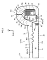
- the inside force cloth 50 and the top and bottom pair of outside force cloths 52, 54 are respectively formed in belt shapes (strap shapes), and are configured such that they stretch less readily than the seat cover 18. As shown in Fig. 3 , a first length direction end portion of the inside force cloth 50 is fastened and fixed to the rear face of the rear wall portion 26C of the side-frame 26R by a bolt 62 and a nut 64.
- a length direction intermediate portion of the inside force cloth 50 extends towards the seat front side, passes to the seat width direction inside of the side-frame 26R, is inserted through an insertion hole 94 formed in a frame attachment section 78R of the resin seatback spring 22, described later, and is also inserted inside a slit portion 66 formed to a front portion side of the pad side portion 38.
- the slit portion 66 extends in the seat front-rear direction between the side airbag device 20 and the sewn portion 42 of the seat cover 18.
- a length direction second end portion of the inside force cloth 50 that is inserted inside the slit portion 66 is sewn to the sewn portion 42.
- the upper side outside force cloth 52 (see Fig. 3 ) is disposed at the same height as the inside force cloth 50, and a length direction first end portion of the upper side outside force cloth 52 is fastened and fixed to the rear face of the rear wall portion 26C by the bolt 62 and the nut 64.
- a length direction intermediate portion of the outside force cloth 52 extends towards the seat front side, passes to the seat width direction outside of the side airbag device 20 and is also inserted inside the slit portion 66.
- a length direction second end portion of the outside force cloth 52 is sewn to the sewn portion 42.
- the lower side outside force cloth 54 (see Fig. 5 ) is disposed below the upper side outside force cloth 52, and a length direction first end portion of the lower side outside force cloth 54 is fastened and fixed to the rear face of the rear wall portion 26C by a bolt 68 and a nut 70.
- a length direction intermediate portion of the outside force cloth 54 extends towards the seat front side, passes to the seat width direction outside of the side airbag device 20, and is also inserted inside the slit portion 66 described above.
- a length direction second end portion of the outside force cloth 54 is sewn to the sewn portion 42.
- configuration may also be made such that the respective length direction first end portions of the inside force cloth 50 and the upper and lower outside force cloths 52, 54 are not directly fixed to the rear wall portion 26C (the side-frame 26R), but are indirectly fixed to the side-frame 26R through brackets.
- the inside force cloth 50 impinges on the seat width direction inside end portion of the front wall portion 26A and the seat width direction inside end portion of the rear wall portion 26C, however configuration may be made with additional protective members to protect the impinging locations.
- Such protective members may be sewn to the inside force cloth 50, or may be attached to the respective seat width direction inside end portions of the front wall portion 26A and the rear wall portion 26C.
- the side airbag device 20 configured as described above, when the inflator 46 actuates, a large volume of gas is ejected inside the side airbag 48, and the side airbag 48 inflates inside the door-side side portion 12A.
- the side airbag 48 inflates, the inside force cloth 50 and the top and bottom pair of outside force cloths 52, 54 are imparted with inflation pressure of the side airbag 48 and stretch. Back inflation pressure is accordingly concentrated on the sewn portion 42 of the seat cover 18, rupturing the thread with which the sewn portion 42 is sewn.
- the sewn portion 42 splits open, and the side airbag 48 inflates and deploys through the ruptured portion towards the seat front side of the door-side side portion 12A, namely between an occupant seated in the vehicle seat 10 and the side door.
- Configuration is accordingly such that an occupant is protected from the impact of for example a side-on collision.
- the resin seatback spring 22 is formed from a resin material, and as shown in Fig. 1 to Fig. 5 , is integrally molded including a backboard section 72 disposed at a back face of the seatback 12, a bottom side back spring section 74 (resin spring section) disposed between the left and right side-frames 26R, 26L further towards the seat front side than the backboard section 72, a top side back spring section 76 disposed above the bottom side back spring section 74 and coupled to the backboard section 72, and a left and right pair of frame attachment sections 78R, 78L supported by the left and right side-frames 26R, 26L of the seatback frame 14 and also coupled to the backboard section 72 and the bottom side back spring section 74.
- the backboard section 72 is configured including a board body 72A formed slightly smaller than the seatback frame 14, and the anchor portion 72B that extends from an outer peripheral portion of the board body 72A towards the seat front side.
- the board body 72A is formed in a substantially rectangular flat plate shape slightly smaller than the inner peripheral rim of an insertion hole formed in the rectangular frame shaped seatback frame 14.
- the board body 72A is disposed at the back face of the seatback 12 in a state with the plate thickness direction aligned in the seatback 12 front-rear direction.
- the board body 72A is capable of passing through the inside of the seatback frame 14.
- the anchor portion 72B is provided at an upper end portion and both seat width direction end portions of the outer peripheral section of the board body 72A, and is formed in an inverted U-shape as viewed along the seat front-rear direction.
- the anchor portion 72B is configured with a U-shape cross-section, opening towards the seat rear side.
- the anchor portion 72B is employed as a cover anchor portion for anchoring the outer peripheral anchor member 40 that is attached to the outer peripheral portion of the seat cover 18, as described above.
- the anchor portion 72B also functions to reinforce the plate shaped board body 72A, raising the overall face rigidity of the backboard section 72.
- the bottom side back spring section 74 is configured including 3 back spring body sections 80U, 80M, 80L, that are disposed parallel to each other in 3 tiers from top to bottom in the seatback height direction.
- the back spring body sections 80U, 80M, 80L are each formed in an overall elongated plate shape, and disposed in a state in which their length directions run along the seat width direction and their plate thickness directions run along the seat front-rear direction. Both length direction end portions of each of the back spring body sections 80U, 80M, 80L are coupled to left and right coupling portions 78C that are respectively provided with left and right frame attachment sections 78R, 78L.
- the 3 back spring body sections 80U, 80M, 80L accordingly span between the left and right frame attachment sections 78R, 78L, and are coupled together in the seatback height direction by the left and right frame attachment sections 78R, 78L.
- the number of back spring body sections 80 (resin spring sections) that configure the bottom side back spring section 74 is optional, and can be appropriately modified according to a relationship with a required cushioning performance. Configuration may accordingly be made with one back spring body section with an increased top-bottom width, or conversely configuration may be made with 2 or 4 or more plural back body spring sections.
- a left and right pair of slack portions 80A are formed at a seat width direction central side of each of the back spring body sections 80U, 80M, 80L.
- the slack portions 80A are formed at each of the left and right sides of a length direction central portion (see the single dotted dashed lines in Fig. 3 and Fig. 5 ) of each of the back spring body sections 80U, 80M, 80L.
- the slack portions 80A are formed with a wave profile by connecting together plural individual curved faces along the seat width direction.
- the back spring body sections 80U, 80M, 80L are configured such that the slack portions 80A resiliently extend when load is applied towards the backboard section 72 side (the seat rear side), and the back spring body sections 80U, 80M, 80L accordingly undergo bowing deformation (resilient deformation) towards the backboard section 72 side that is in the load application direction.
- the back spring body sections 80U, 80M, 80L are disposed at positions separated by a specific distance from the seat front side of the backboard section 72, described above, and bowing deformation is possible within the range of a gap 82 formed between the two respective sections.
- the backboard section 72 also functions as a restricting member that restricts the amount of bowing of the back spring body sections 80U, 80M, 80L to a specific amount or less.
- the slack portions 80A of the back spring body sections 80U, 80M, 80L are also set with a draft angle (taper shape) such that in resin molding employing a slide mold, not shown in the drawings, the slide mold can be removed from the mold from one side or the other in the seatback height direction (the bottom side in this case).
- the top side back spring section 76 is provided at a position separated by a specific distance in the seatback height direction from the bottom side back spring section 74.
- the top side back spring section 76 has basically the same configuration as the back spring body sections 80U, 80M, 80L described above, is provided with slack portions 76A that are similar to the slack portions 80A described above.
- through holes 84 are formed in both length direction end portions of the top side back spring section 76, and resin clips 86 (see Fig. 2 ) are inserted through the through holes 84 and fit into and are anchored into the attachment holes 34 (see Fig. 1 ) in the side-frames 26R, 26L.
- the top side back spring section 76 is thereby fixed to the side-frames 26R, 26L.
- the left and right frame attachment sections 78R, 78L are disposed at the same height in the seatback 12 as the height at which the side airbag 48 is disposed.
- the frame attachment sections 78R, 78L are formed with an open cross-section profile, open towards the seat rear side when viewed in horizontal cross-section.
- the frame attachment sections 78R, 78L fit together with the front sides of the left and right side-frames 26R, 26L (see Fig. 3 to Fig. 5 ).
- each of the frame attachment sections 78R, 78L is configured including a supported portion 78A supported by the front side of the side-frames 26R, 26L, a fixing portion 78B that extends from the seat width direction outside end portion of the supported portion 78A towards the seat rear side, and the coupling portion 78C that extends diagonally from the seat width direction inside end portion of the supported portion 78A towards the seat rear side and the seat width direction inside.
- the frame attachment sections 78R, 78L fit together with the front sides of the side-frames 26R, 26L.
- configuration may be made such that the frame attachment sections 78R, 78L do not directly fit together with the front sides of the side-frames 26R, 26L, with a separate member (for example a resilient member) interposed between the two (a configuration wherein the frame attachment sections 78R, 78L indirectly fit together with the front sides of the side-frames 26R, 26L).
- a separate member for example a resilient member
- the supported portion 78A faces (contacts) the front wall portion 26B from the seat front side
- the fixing portion 78B faces (contacts) the side wall portion 26A from the seat width direction outside.
- Each fixing portion 78B is formed with a top and bottom pair of through holes 88 (see Fig. 1 ), and a resin clip 90 (see Fig. 2 ) is inserted through each through hole 88 and fitted into and anchored to the corresponding attachment hole 32 in the side wall portion 26A.
- the fixing portions 78B (the coupling portions 78C) are thereby fixed to the side-frame 26R and the side-frame 26L.
- various approaches may be adopted for the method of fixing the coupling portions 78C to the side-frames 26R, 26L including, for example, a configuration wherein resin clips (fixing members) are integrally formed to the fixing portions 78B and are fitted into the attachment holes 32, configurations involving fastening with fasteners such as rivets, screws, or bolts and weld nuts, or a configuration involving bonding with structural adhesive.
- Each coupling portion 78C is inclined to the seat front-rear direction so as to head towards the seat width direction inside on progression towards the seat rear side, and extends from the vicinity of the seat width direction inside end portion of the front wall portion 26B to the vicinity of the back face of the seatback 12.
- Length direction end portions of the 3 top-to-bottom back spring body sections 80U, 80M, 80L are coupled to front-rear direction intermediate portions of the coupling portions 78C, and a front end portion of each of the anchor portions 72B of the backboard section 72 is coupled to a rear end portion of the respective coupling portion 78C.
- the left and right coupling portions 78C face the left and right side-frames 26R, 26L from the seat width direction insides, and the left and right side-frames 26R, 26L are covered from the seat width direction insides by the left and right coupling portions 78C (the frame attachment sections 78R, 78L) at the height at which the left and right coupling portions 78C are provided (the bottom side portion of the seatback frame 14).
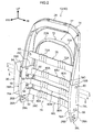
- a top and bottom pair of openings 92 are formed to the coupling portion 78C of the frame attachment section 78R disposed at the vehicle width direction outside.
- Each of the openings 92 is formed in a substantially rectangular shape with the front end sides thereof configured in a circular arc shape (substantially circular shape).
- the openings 92 are disposed at positions in the seatback height direction that are displaced with respect to the 3 back spring body sections 80U, 80M, 80L.
- a top side opening 92 is disposed at a height between the upper tier back spring body section 80U and the middle tier back spring body section 80M, and a bottom side opening 92 is disposed at a height between the middle tier back spring body section 80M and the lower tier back spring body section 80L.
- the top side opening 92 is formed at a position facing along the seat width direction towards the top side stud bolt 56 and nut 58 out of the previously described top and bottom pairs of stud bolts 56 and nuts 58.
- the bottom side opening 92 is disposed at a position facing along the seat width direction towards the bottom side stud bolt 56 and nut 58 (see Fig. 2 ).
- Each opening 92 is configured such that the nut 58 and a tool (for example a socket wrench) for rotating the nut 58 can be inserted therein. Configuration is made such that the stud bolts 56 and the nuts 58 can be screwed together by inserting the nuts 58 and the tool through the openings 92 from the seat width direction inside.
- the shape of the openings 92 is not limited to the shape shown in Fig. 2 , and the openings 92 may be formed with other shapes (for example a circular shape or a rectangular shape). However a circular or close-to circular shape is preferable from the perspective of avoiding stress concentration.
- the elongated slit shaped insertion hole 94 extending in the seatback height direction is formed to an upper portion side of the supported portion 78A of the frame attachment section 78R disposed at the vehicle width direction outside.
- the insertion hole 94 is disposed at the same height as the upper tier back spring body section 80U and facing the front wall portion 26B of the side-frame 26R. As explained above, the length direction intermediate portion of the inside force cloth 50 is inserted into the insertion hole 94.
- the side portion (the vehicle width direction inside side portion) at the opposite side to the door-side side portion 12A of the seatback 12 is not provided with the side airbag device 20.
- the vehicle width direction inside-frame attachment section 78L is accordingly configured such that the openings 92 and the insertion hole 94 are not formed thereto.
- other configuration elements of the seatback 12 described above are formed with shapes to give left-right symmetry.
- the resin seatback spring 22 is mounted to the seatback frame 14 from the seat front side. Configuration is made such that the backboard section 72 is passed through the inside of the seatback frame 14 and disposed at the back face side of the seatback frame 14.
- the left and right frame attachment sections 78R, 78L fit together with the front sides of the left and right side-frames 26R, 26L.
- the load input to the top side back spring section 76 is supported by the left and right side-frames 26R, 26L through both length direction end portions of the top side back spring section 76.
- the load input to the bottom side back spring section 74 is supported by the left and right side-frames 26R, 26L through the left and right frame attachment sections 78R, 78L.
- the frame attachment sections 78R, 78L are formed with an open cross-section profile towards the seat rear side, and fit together with the front sides of the left and right side-frames 26R, 26L.
- the support provided by the bottom side back spring section 74 can accordingly be stabilized since reaction force from the left and right side-frames 26R, 26L can be well supported by the left and right frame attachment sections 78R, 78L.
- the bottom side back spring section 74 and the top side back spring section 76 are made out of resin and integrated together with the backboard section 36.
- the number of components and the number of assembly operations can accordingly be reduced, and also a reduction in weight and reduction in costs can be achieved in comparison to cases in which the spring sections are configured from seatback springs made out of metal.
- the left and right frame attachment sections 78R, 78L of the resin seatback spring 22 are disposed at the disposal height of the side airbag 48 of the seatback 12.
- the top and bottom pairs of stud bolts 56 and nuts 58 that fasten and fix the side airbag device 20 to the side-frame 26R are covered by the coupling portion 78C of the vehicle width direction outside-frame attachment section 78R.
- the top and bottom pair of openings 92 is formed to the frame attachment section 78R at positions facing the top and bottom pairs of stud bolts 56 and nuts 58.
- the side airbag device 20 can thereby be fastened and fixed to the side-frame 26R by inserting the nuts 58 and the tool (for example a socket wrench) through the openings 92 and screwing the nuts 58 onto the stud bolts 56 even in cases where the resin seatback spring 22 is assembled to the seatback frame 14 before the side airbag device 20 is assembled to the side-frame 26R. Good characteristics can accordingly be achieved in assembly operations of the side airbag device 20 to the side-frame 26R.
- the tool for example a socket wrench
- the top and bottom pair of openings 92 are disposed displaced with respect to the 3 back spring body sections 80U, 80M, 80L in the seatback height direction. Load input to the back spring body sections 80U, 80M, 80L can accordingly be well-supported at locations in the frame attachment section 78R at which the openings 92 are not formed. The support of the 3 back spring body sections 80U, 80M, 80L can thereby be stabilized.
- the top and bottom pair of openings 92 also respectively face towards the top and bottom pair of stud bolts 56 provided to the inflator 46. Good assembly operation characteristics can accordingly be achieved when the inflator 46 (the side airbag device 20) provided with the pair of stud bolts 56 is being assembled to one of the side-frames.
- each of the inside force cloth 50 and the top and bottom pair of outside force cloths 52, 54 has a first end portion fixed to the rear face of the rear wall portion 26C of the side-frame 26R and a second end portion sewn to the sewn portion 42 of the seat cover 18.
- the inside force cloth 50 and the top and bottom pair of outside force cloths 52, 54 stretch when the side airbag 48 provided to the side airbag device 20 inflates.
- the back inflation pressure is hence transmitted through the force cloths to the sewn portion 42 of the seat cover 18, thereby promptly splitting open the sewn portion 42 to allow the side airbag 48 to deploy promptly through the split portion.
- an intermediate portion of the inside force cloth 50 is inserted into and passed through the insertion hole 94 formed in the front end portion (the supported portion 78A) of the vehicle width direction outside-frame attachment section 78R.
- the inside force cloth 50 can accordingly be laid out along the shortest path.
- the insertion hole 94 is disposed at the same height as the upper tier back spring body section 80U.
- the insertion hole 94 is formed in the supported portion 78A (front end portion) of the frame attachment section 78R, namely at a position distant from a connection portion 81 (see Fig. 3 ) between the upper tier back spring body section 80U and the coupling portion 78C.
- the upper side outside force cloth 52 is disposed at the same height as the inside force cloth 50, so the sewn portion 42 can be made to split open even more promptly at this height.
- the sewn portion 42 can however be made to promptly split open over a wide range in the top-to-bottom direction (the seatback height direction) due to providing the top and bottom pair of outside force cloths 52, 54, thereby enabling the side airbag deployment direction to be stabilized.
- the deployment performance of the side airbag 48 can be enhanced for the above reasons.
- configuration is made with the insertion hole 94 formed in the supported portion 78A, however the inventions of claims 1 to 10 is not limited thereto, and as shown in the modified example illustrated in Fig. 6 , configuration may be made such that the insertion hole 94 is formed in a front end side of the coupling portion 78C.
- the layout path of the inside force cloth 50 can be made short and the support of the upper tier back spring body section 80U can be suppressed from being destabilized at the disposal height of the insertion hole 94.
- the inside force cloth 50 can be laid out such that the inside force cloth 50 does not impinge on the front wall portion 26A of the side-frame 26R.
- the openings 92 are not formed to the vehicle width direction inside-frame attachment section 78L, however the inventions of claims 1 to 10 are not limited thereto, as long as an opening is provided to at least one out of left and right side-frame attachment sections.
- the resin seatback springs may be employed for both a driver's seat and passenger seat in cases where an opening is formed to both left and right frame attachment sections. A saving in manufacturing cost may thereby be achieved.
- a good seating sensation can be achieved for an occupant due to the shape of the resin seatback springs having left-right symmetry, in comparison to cases where the shape of the resin seatback springs do not have left-right symmetry.
- the same point also applies to the insertion hole 94.
- configuration is made wherein the side airbag device 20 is provided with the inside force cloth 50 and the top and bottom pair of the outside force cloths 52, 54, however the invention of claims 1 to 4 are not limited thereto, and configuration may be made with the force cloth(s) omitted. Appropriate modifications may also be made to the number and placement of the inside force cloth and the outside force cloths.
- configuration is made wherein the top and bottom pair of openings 92 are disposed displaced from the 3 back spring body sections 80U, 80M, 80L (resin spring sections) in the seatback height direction.
- Claims 1 and 2 of the invention are however not limited thereto, and configuration may be made such that the openings are disposed at the same heights as the resin spring sections.
- configuration is made such that the openings 92 are respectively formed at positions in the first frame attachment section 78R facing towards the pairs of the stud bolts 56 and the nuts 58.
- the inventions according to claims 1 to 8 and 10 are however not limited thereto, and appropriate modifications may be made to the number of openings according to the fixing structure of the side airbag device.
- configuration is made with the fixing portions 78B provided to the left and right frame attachment sections 78R, 78L, however the inventions according to claims 1 to 10 are not limited thereto, and configuration may be made with the fixing portions 78B omitted.
- configuration is for example such that the supported portion 78A is fixed to the side-frame 26R or the side-frame 26L using for example clips.
- configuration is made such that the backboard section 72, the left and right frame attachment sections 78R, 78L, the bottom side back spring section 74 and the top side back spring section 76 are integrally molded.
- the inventions of claims 1 to 10 are not limited thereto, and configuration may be made whereby each component is molded separately, and then integrated together by for example welding.
- configuration is made wherein the openings 92 are always open.
- the inventions of claims 1 to 10 are however not limited thereto, and configuration may be made including door portions that are integral to the frame attachment section(s) or integrated to the frame attachment sections(s) for opening or closing the openings.
Landscapes
- Engineering & Computer Science (AREA)
- Mechanical Engineering (AREA)
- Aviation & Aerospace Engineering (AREA)
- Transportation (AREA)
- Seats For Vehicles (AREA)
- Air Bags (AREA)
Abstract
Description
- The present invention relates to a vehicle seat and a resin seatback spring.
- In a following Patent Document 1, it is disclosed that a spring (a seatback spring) that spans between a left and right pair of side-frames provided to a seatback frame is made out of resin, from the perspective of achieving a reduction in the weight of a vehicle seat.
-
- Patent Document 1, Japanese Patent Application Laid-Open (JP-A) No.
2004-138156 - However, a side airbag device is sometimes assembled to a side-frame of the seatback frame. It is accordingly demanded that no deterioration in assembly operation characteristics of the side airbag device results from the presence of the resin seatback spring.
- In consideration of the above circumstances, an object of the present invention is to obtain a vehicle seat and resin seatback spring that allows good assembly operation characteristics of a side airbag device to a side-frame of a seatback frame.
- A vehicle seat of a first aspect of the present invention includes: a seatback frame including left and right side-frames; a side airbag device that is disposed at a seat width direction outside of a first of the left or right side-frames and is fixed to the first side-frame from the seat width direction inside by a fixing member; and a resin seatback spring including a resin spring section disposed between the left and right side-frames and left and right frame attachment sections that are respectively supported at front sides of the left and right side-frames, that extend from seat width direction insides of the left and right side-frames towards a seat rear side, and that are coupled to the resin spring section, the resin seatback spring being formed with an opening at a position facing the fixing member in a first of the frame attachment sections supported at the first side-frame.
- In the vehicle seat of the first aspect, the seatback frame includes the left and right side-frames, and the side airbag device is disposed at the seat width direction outside of the first side-frame. The side airbag device is fastened and fixed to the first side-frame from the seat width direction inside by the fixing member. The left and right frame attachment sections provided to the resin seatback spring are respectively supported at the front sides of the left and right side-frames, and the frame attachment sections are coupled to the resin spring section disposed between the left and right side-frames.
- It is conceivable that the fixing member would be covered by the first frame attachment section supported at the first side-frame, since the left and right frame attachment sections extend from the seat width direction insides of the left and right side-frames towards the seat rear side. However, in the present aspect, the opening is formed to the first frame attachment section at a position facing the fixing member. During manufacture of the present vehicle seat, it is accordingly possible to perform a fixing operation of the side airbag device to the first side-frame through the opening even in cases where the resin seatback spring is assembled to the seatback frame before assembling the side airbag device to the first side-frame. Good assembly operation characteristics can therefore be achieved in assembly of the side airbag device to the side-frame.
- A vehicle seat of a second aspect of the present invention is the vehicle seat of the first aspect wherein the resin spring section includes plural back spring body sections disposed in a row along a seatback height direction, and the opening is displaced in the seatback height direction with respect to the plural back spring body sections.
- In the vehicle seat of the second aspect, the resin spring section of the resin seatback spring includes the plural back spring body sections disposed in a row along the seatback height direction. The plural back spring body sections are supported by the left and right side-frames through the left and right frame attachment sections when load from an occupant is input to the back spring body sections. In the present aspect, the opening formed in the first frame attachment section is displaced in the seatback height direction with respect to the plural back spring body sections. The load can accordingly be well supported at the locations in the first frame attachment section where the opening is not formed. The support from the plural back spring body sections can accordingly be stabilized.
- A vehicle seat of a third aspect of the present invention is the vehicle seat of either the first or the second aspect further including: a seatback pad supported by the seatback frame; a seat cover covering the seatback pad; and an inside airbag inflation pressure transmission member, a first end portion of the inside airbag inflation pressure transmission member being fixed to a rear end side of the first side-frame, an intermediate portion of the inside airbag inflation pressure transmission member being inserted through an insertion hole formed in the first frame attachment section, and a second end portion of the inside airbag inflation pressure transmission member being sewn to a sewn portion of the seat cover.
- In the vehicle seat of the third aspect, back inflation pressure when a side airbag provided to the side airbag device inflates is transmitted to the sewn portion of the seat cover through the inside airbag inflation pressure transmission member, of which the first end portion is fixed to the rear end side of the first side-frame and the second end portion is sewn to the sewn portion of the seat cover. The sewn portion of the seat cover can accordingly be made to promptly split open, and the side airbag can be made to inflate and deploy promptly from the split portion. Moreover, the layout path of the inside airbag inflation pressure transmission member can also be shortened since the intermediate portion of the inside airbag inflation pressure transmission member is inserted through the insertion hole formed in the first frame attachment section of the resin seatback spring.
- A vehicle seat of a fourth aspect of the present invention is the vehicle seat of the third aspect wherein the insertion hole is formed in a front end side of the first frame attachment section and is disposed at the same height as any one of a plurality of the resin spring sections.
- In the vehicle seat of the fourth aspect, the insertion hole formed in the first frame attachment section of the resin seatback spring for insertion of the inside airbag inflation pressure transmission member is disposed at the same height as any one of the plurality of the resin spring sections. It is therefore conceivable that when load from an occupant is input to that particular resin spring section stress would be concentrated at the periphery of the insertion hole in the first frame attachment section. However, in the present aspect, the insertion hole is formed at the front end side of the first frame attachment section, namely at a position away from the connection portion between that particular resin spring section and the first frame attachment section. Stress can accordingly be suppressed from being concentrated at the periphery of the insertion hole when load from an occupant is input to that particular resin spring section. Moreover, when the opening is disposed displaced in the seatback height direction with respect to the plurality of the resin spring sections as described in the second aspect, the opening and the insertion hole are also displaced in the seatback height direction. Weakening of the first frame attachment section at the height at which that particular resin spring section and the insertion hole are formed can thereby be suppressed. The support from that particular resin spring section can thereby be stabilized.
- A vehicle seat of a fifth aspect of the present invention is the vehicle seat of either the third or the fourth aspect further including an outside airbag inflation pressure transmission member, a first end portion of the outside airbag inflation pressure transmission member being fixed to the rear end side of the side-frame, an intermediate portion of the outside airbag inflation pressure transmission member passing the side airbag device on the seat width direction outside, and a second end portion of the outside airbag inflation pressure transmission member being sewn to the sewn portion.
- In the vehicle seat of the fifth aspect, when the side airbag provided to the side airbag device inflates, back inflation pressure is transmitted to the sewn portion of the seat cover through the outside airbag inflation pressure transmission member of which the first end portion is fixed to the rear end side of the first side-frame, the intermediate portion passes the side airbag device on the seat width direction outside, and the second end portion is sewn to the sewn portion of the seat cover. The sewn portion of the seat cover can accordingly be made to split open even more promptly. There is moreover no need to form an insertion hole through which to insert the intermediate portion of the outside airbag inflation pressure transmission member to the frame attachment section of the resin seatback spring due to the intermediate portion of the outside airbag inflation pressure transmission member passing the side airbag device on the seat width direction outside. It is accordingly possible to reduce the number of insertion holes formed to the frame attachment section.
- A vehicle seat of a sixth aspect of the present invention is the vehicle seat of the fifth aspect further including a top and bottom pair of a outside airbag inflation pressure transmission members, the top side outside airbag inflation pressure transmission member being disposed at the same height as the inside airbag inflation pressure transmission member, and the bottom side outside airbag inflation pressure transmission member being disposed below the top side outside airbag inflation pressure transmission member.
- In the vehicle seat of the sixth aspect, due to the top side outside airbag inflation pressure transmission member of the top and bottom pair of outside airbag inflation pressure transmission members being disposed at the same height as the inside airbag inflation pressure transmission member, the sewn portion of the seat cover can be made to split open even more promptly at the height at which the top side outside airbag inflation pressure transmission member and the inside airbag inflation pressure transmission member are disposed. Moreover, the sewn portion of the seat cover can be made to promptly split open over a wide range in the top-bottom direction (the seatback height direction) due to providing the top and bottom pair of outside airbag inflation pressure transmission members. The deployment direction of the side airbag can accordingly be stabilized.
- A vehicle seat of a seventh aspect of the present invention is the vehicle seat of any one of the first aspect to the sixth aspect wherein the frame attachment sections are formed with open cross-section profiles that are open to the seat rear side, and that fit together with the front sides of the side-frames.
- In the vehicle seat of the seventh aspect, when load from an occupant is input to the resin spring section of the resin seatback spring, reaction force from the left and right side-frames is borne by the left and right frame attachment sections. The frame attachment sections are formed with open cross-section profiles that are open to the seat rear side, and fit together with the front sides of the left and right side-frames. The support from the plural resin spring sections can accordingly be stabilized since the reaction force from the left and right side-frames can be well supported by the left and right frame attachment sections.
- A vehicle seat of an eighth aspect of the present invention is the vehicle seat of any one of first aspect to the seventh aspect wherein the resin seatback spring further includes a backboard section that is disposed at a seatback back face to the seat rear side of a plurality of the resin spring sections and is coupled to the left and right frame attachment sections.
- In the vehicle seat of the eighth aspect, the number of components and the number of processes to assemble components to the seatback frame can be reduced since the resin seatback spring is provided with the backboard section disposed at the seatback back face.
- A vehicle seat of a ninth aspect of the present invention is the vehicle seat of any one of first aspect to the eighth aspect wherein: the fixing member includes a pair of top and bottom stud bolts provided to a gas generation unit that is installed to the side airbag device and a pair of top and bottom nuts screwed onto the pair of stud bolts; the side airbag device is fastened and fixed to the first side-frame by inserting the pair of stud bolts through the first side-frame from the seat width direction outside and screwing the pair of nuts onto the pair of stud bolts; the resin seatback spring includes 3 of the resin spring sections displaced in a seatback frame height direction with respect to the pair of stud bolts and the pair of nuts; and the opening is formed in the first frame attachment section at respective positions facing the pair of stud bolts and the pair of nuts.
- In the ninth aspect, the resin seatback spring is provided with 3 of the resin spring sections disposed between the left and right side-frames in a row in the seatback height direction. The resin spring sections are disposed displaced in the seatback frame height direction with respect to the pair of stud bolts and with respect to the pair of nuts that fasten and fix the gas generation unit that is installed to the side airbag device to the first side-frame. The openings are formed in the first frame attachment section at respective positions facing the pair of stud bolts and the pair of nuts. Good assembly operation characteristics can thereby be achieved when assembling the gas generation unit (the side airbag device) provided with the pair of stud bolts to the first side-frame. Moreover, since the 3 resin spring sections and 2 openings are disposed displaced in the seatback height direction, similarly to the second aspect, the support from the plural resin spring sections can be stabilized.
- A resin seatback spring of a tenth aspect of the present invention includes: a resin spring section disposed between left and right side-frames that are provided to a seatback frame of a vehicle seat; and left and right frame attachment sections respectively including left and right supported portions respectively supported at a front sides of the left and right side-frames, and left and right coupling portions that extend towards a seat rear side from respective seat width direction inside end portions of the left and right supported portions and are coupled to the resin spring section, wherein an opening is formed in one of the left or right coupling portions.
- In the resin seatback spring of the tenth aspect, the left and right supported portions provided to the left and right frame attachment sections are respectively supported at the front sides of the left and right side-frames of the seatback frame. The left and right coupling portions that extend towards the seat rear side from seat width direction inside end portions of the left and right supported portions are coupled to the resin spring section disposed between the left and right side-frames.
- Portions of the left and right side-frames are covered from the seat width direction inside by the left and right coupling portions, due to the left and right coupling portions extending towards the seat rear side from seat width direction inside end portions of the left and right supported portions as described above. It is therefore conceivable that during manufacture of the vehicle seat, the coupling portion on the first side-frame side would be a nuisance in the assembly operation of the side airbag device in cases where the resin seatback spring is assembled to the seatback frame before the side airbag device is assembled to the first side-frame. In other words, it is conceivable that the coupling portion on the first side-frame side would be a nuisance when the side airbag device disposed at the seat width direction outside of the first side-frame is being fixed to the first side-frame with the fixing member from the seat width direction inside. However, in the present aspect, since the opening is formed to one of the left and right coupling members, the fixing operation of the side airbag device to the first side-frame can be performed through the opening. Good assembly operation characteristics can accordingly be achieved for the assembly of the side airbag device to the side-frame.
- As explained above, the vehicle seat according to the present invention allows good assembly operation characteristics of a side airbag device to a side-frame of a seatback frame.
-
-
Fig. 1 is an exploded perspective view illustrating a seatback of a vehicle seat according to an exemplary embodiment of the present invention. -
Fig. 2 is a perspective view illustrating an assembled state of a resin spring integral backboard to the seatback frame illustrated inFig. 1 . -
Fig. 3 is a horizontal cross-section taken along line 3-3 inFig. 2 . -
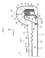
Fig. 4 is a horizontal cross-section taken along line 4-4 inFig. 2 . -
Fig. 5 is a horizontal cross-section taken along line 5-5 inFig. 2 . -
Fig. 6 is a horizontal cross-section corresponding toFig. 3 and illustrating a modified example of an exemplary embodiment of the present invention. - Explanation follows regarding a
vehicle seat 10 andresin seatback spring 22 according to an exemplary embodiment of the present invention, with reference toFig. 1 to Fig. 6 . In the drawings the arrow FR indicates a vehicle front side, the arrow UP indicates the vehicle top side, and the arrow IN indicates the vehicle width direction inside, as appropriate. -
Fig. 1 is an exploded perspective view illustrating aseatback 12 corresponding to a backrest of thevehicle seat 10 according to the present exemplary embodiment. Note that inFig. 1 the configuration elements are each depicted as viewed from slightly different angles from each other. Thevehicle seat 10 is provided with a seat cushion, not shown in the drawings, for seating an occupant, and theseatback 12 is reclinably coupled at a rear edge portion of the seat cushion. - As shown in
Fig. 1 , theseatback 12 is configured including aseatback frame 14 that is made from metal and configures a framework member of theseatback 12, aseatback pad 16 that is supported by theseatback frame 14, aseat cover 18 that covers theseatback pad 16, and aresin seatback spring 22 attached to theseatback frame 14. As shown inFig. 2 , theseatback 12 is further configured including a side airbag device 20 (a side airbag module, not illustrated inFig. 1 ) attached to theseatback frame 14. Detailed explanation follows regarding each of the configuration elements. - As shown in
Fig. 1 andFig. 2 , theseatback frame 14 is formed in a rectangular frame shape in front view (indicating a view from the front face of the vehicle; in the following explanation the direction of the vehicle, the direction of thevehicle seat 10 and the direction of theseatback 12 are the same as each other). More specifically, configuration includes a left and right pair of side-frames upper frame 28 that is formed in an inverted U-shape and connects together top end portions of the left and right side-frames lower frame 30 that connects together bottom end portions of the left and right side-frames seatback 12 is produced by press forming each of the four members, including theupper frame 28, however another frame structure may be employed. For example, configuration may be made with just the upper frame configured by pipe material bent into an inverted U-shape. - As shown in
Fig. 1 to Fig. 5 , the side-frames side wall portion 26A, afront wall portion 26B and arear wall portion 26C. Each of the side-frames 26 is formed with a substantially C-shaped horizontal cross-section that opens towards the seat width direction inside. Theside wall portion 26A extends along the seat front-rear direction, and thefront wall portion 26B and therear wall portion 26C respectively extend from a front edge and a rear edge of theside wall portion 26A towards the seat width direction inside. The width of therear wall portion 26C is set sufficiently wider than the width of thefront wall portion 26B. As shown inFig. 1 , plural (in this case 2) attachment holes 32 are formed in a lower portion of theside wall portion 26A with a separation in the top-bottom direction, and anattachment hole 34 is formed in an upper portion of therear wall portion 26C. The attachment holes 32, 34 correspond with theresin seatback spring 22. - As shown in
Fig. 1 , theseatback pad 16 is configured including a padcentral portion 36 configured by a foam body such as urethane foam, and a left and right pair ofpad side portions 38. An upper edge side of the padcentral portion 36 is anchored to theupper frame 28 of theseatback frame 14 from the seat top side, and a lower edge side of the padcentral portion 36 is anchored from the seat bottom side to a connecting rod, not shown in the drawings, that connects together bottom end portions of the side-frames central portion 36 is supported from the seat rear side by a bottom side backspring section 74 and a top side backspring section 76 provided to theresin seatback spring 22. - The
pad side portions 38 are formed with a substantially C-shaped cross-sectional profile. Thepad side portions 38 are mounted so as to wrap around the side-frames Fig. 3 to Fig. 5 ). Thepad side portions 38 are shaped to bulge out further towards the seat front side than the padcentral portion 36, securing side support properties for an occupant. - As shown in
Fig. 1 , theseat cover 18 is formed in a size that enables it to be covered over theseatback pad 16 from the front side. As shown inFig. 3 to Fig. 5 , an outerperipheral anchor member 40 is attached by sewing to an appropriate position of an outer peripheral portion of theseat cover 18. The outerperipheral anchor member 40 is inserted into ananchor portion 72B of theresin seatback spring 22 from the seat rear side and anchored thereto. The outer peripheral portion of theseat cover 18 is thereby detachably anchored to theanchor portion 72B. Theseat cover 18 is further provided with plural anchor portions, not shown in the drawings, and the anchor portions are anchored to theresin seatback spring 22. - The
seat cover 18 is provided with a sewnportion 42 that extends in the seatback height direction at a location facing a front edge portion at the vehicle width direction outside of thepad side portion 38. The sewnportion 42 is configured so as to split open together with thepad side portion 38 during inflation and deployment of aside airbag 48, described later. - As shown in
Fig. 3 to Fig. 5 , theside airbag device 20 is disposed inside a door-side side portion 12A of the seatback 12 (a side portion at the side of a side door, not shown in the drawings). Theside airbag device 20 is disposed further to the seat width direction outside than the vehicle width direction outside side-frame 26R that is disposed inside the door-side side portion 12A (seeFig. 2 ). Theside airbag device 20 is configured including an inflator 46 (a gas generation unit), aside airbag 48, an inside force cloth 50 (an inside airbag inflation pressure transmission member), and a top and bottom pair ofoutside force cloths 52, 54 (an outside airbag inflation pressure transmission member). Theside airbag 48 is disposed inside the door-side side portion 12A in a folded-up state, unitized with theinflator 46. - The inflator 46 is formed in a circular columnar shape, disposed at a lower side portion of the door-
side side portion 12A with the axial direction (the length direction) aligned in the seatback height direction. A top and bottom pair of stud bolts 56 (fixing members) are provided to an outer peripheral portion of the inflator 46, thestud bolts 56 projecting towards the radial direction outside of theinflator 46. Thestud bolts 56 pass through through-holes formed inside wall portion 26A of the side-frame 26R and project towards the seat width direction inside of theside wall portion 26A. A top and bottom pair of nuts 58 (fixing members) are provided at the seat width direction inside of theside wall portion 26A, and the nuts 58 are screwed onto each of thestud bolts 56. The inflator 46 is thereby fastened and fixed to the side-frame 26R. Namely, during assembly of the inflator 46 (the side airbag device 20) to the side-frame 26R in the present exemplary embodiment, configuration is such that the top and bottom pair ofstud bolts 56 are inserted through the through-holes in theside wall portion 26A from the seat width direction outside, and the nuts 58 are screwed onto thestud bolts 56 from the seat width direction inside of the side-frame 26R. In other words, configuration is made such that the operation to screw the nuts 58 onto the pair of stud bolts 56 (the fixing operation of theside airbag device 20 to the side-frame 26R) is performed from the seat width direction inside of the side-frame 26R. Note that configuration may also be made wherein the inflator 46 is attached to a retainer that is provided with the pair of stud bolts 56 (a configuration wherein the gas generation unit includes the retainer and the inflator). - The inflator 46 described above is connected to an airbag ECU, not shown in the drawings. In the event of a vehicle for example being involved in a side-on collision or rolling over, the airbag ECU determines whether or not to actuate the
side airbag device 20 based on a detection signal from an airbag sensor, not shown in the drawings. Configuration is made such that when the airbag ECU makes determination to actuate the airbag, a specific current is caused to flow to the inflator 46, and a large volume of gas is ejected from theinflator 46. - The
side airbag 48 formed by stitching a sheet shaped base cloth of for example cloth or a resin sheet into a bag shape. The inflator 46 that is housed inside theside airbag 48 is fastened and fixed to the side-frame 26R, thereby attaching theside airbag 48 to the side-frame 26R. Theside airbag 48 is folded up by a specific folding pattern, and is retained in a folded-up state due to being wrapped in a readily rupturingwrap material 60. - The
inside force cloth 50 and the top and bottom pair ofoutside force cloths seat cover 18. As shown inFig. 3 , a first length direction end portion of theinside force cloth 50 is fastened and fixed to the rear face of therear wall portion 26C of the side-frame 26R by abolt 62 and anut 64. A length direction intermediate portion of theinside force cloth 50 extends towards the seat front side, passes to the seat width direction inside of the side-frame 26R, is inserted through aninsertion hole 94 formed in aframe attachment section 78R of theresin seatback spring 22, described later, and is also inserted inside aslit portion 66 formed to a front portion side of thepad side portion 38. Theslit portion 66 extends in the seat front-rear direction between theside airbag device 20 and the sewnportion 42 of theseat cover 18. A length direction second end portion of theinside force cloth 50 that is inserted inside theslit portion 66 is sewn to the sewnportion 42. - The upper side outside force cloth 52 (see
Fig. 3 ) is disposed at the same height as theinside force cloth 50, and a length direction first end portion of the upper side outsideforce cloth 52 is fastened and fixed to the rear face of therear wall portion 26C by thebolt 62 and thenut 64. A length direction intermediate portion of theoutside force cloth 52 extends towards the seat front side, passes to the seat width direction outside of theside airbag device 20 and is also inserted inside theslit portion 66. A length direction second end portion of theoutside force cloth 52 is sewn to the sewnportion 42. - The lower side outside force cloth 54 (see
Fig. 5 ) is disposed below the upper side outsideforce cloth 52, and a length direction first end portion of the lower side outsideforce cloth 54 is fastened and fixed to the rear face of therear wall portion 26C by abolt 68 and anut 70. A length direction intermediate portion of theoutside force cloth 54 extends towards the seat front side, passes to the seat width direction outside of theside airbag device 20, and is also inserted inside theslit portion 66 described above. A length direction second end portion of theoutside force cloth 54 is sewn to the sewnportion 42. Note that configuration may also be made such that the respective length direction first end portions of theinside force cloth 50 and the upper and loweroutside force cloths rear wall portion 26C (the side-frame 26R), but are indirectly fixed to the side-frame 26R through brackets. In the present exemplary embodiment, theinside force cloth 50 impinges on the seat width direction inside end portion of thefront wall portion 26A and the seat width direction inside end portion of therear wall portion 26C, however configuration may be made with additional protective members to protect the impinging locations. Such protective members may be sewn to theinside force cloth 50, or may be attached to the respective seat width direction inside end portions of thefront wall portion 26A and therear wall portion 26C. - In the
side airbag device 20 configured as described above, when the inflator 46 actuates, a large volume of gas is ejected inside theside airbag 48, and theside airbag 48 inflates inside the door-side side portion 12A. When theside airbag 48 inflates, theinside force cloth 50 and the top and bottom pair ofoutside force cloths side airbag 48 and stretch. Back inflation pressure is accordingly concentrated on the sewnportion 42 of theseat cover 18, rupturing the thread with which the sewnportion 42 is sewn. As a result, the sewnportion 42 splits open, and theside airbag 48 inflates and deploys through the ruptured portion towards the seat front side of the door-side side portion 12A, namely between an occupant seated in thevehicle seat 10 and the side door. Configuration is accordingly such that an occupant is protected from the impact of for example a side-on collision. - The
resin seatback spring 22 is formed from a resin material, and as shown inFig. 1 to Fig. 5 , is integrally molded including abackboard section 72 disposed at a back face of theseatback 12, a bottom side back spring section 74 (resin spring section) disposed between the left and right side-frames backboard section 72, a top side backspring section 76 disposed above the bottom side backspring section 74 and coupled to thebackboard section 72, and a left and right pair offrame attachment sections frames seatback frame 14 and also coupled to thebackboard section 72 and the bottom side backspring section 74. - The
backboard section 72 is configured including aboard body 72A formed slightly smaller than theseatback frame 14, and theanchor portion 72B that extends from an outer peripheral portion of theboard body 72A towards the seat front side. Theboard body 72A is formed in a substantially rectangular flat plate shape slightly smaller than the inner peripheral rim of an insertion hole formed in the rectangular frame shapedseatback frame 14. Theboard body 72A is disposed at the back face of theseatback 12 in a state with the plate thickness direction aligned in theseatback 12 front-rear direction. Theboard body 72A is capable of passing through the inside of theseatback frame 14. - The
anchor portion 72B is provided at an upper end portion and both seat width direction end portions of the outer peripheral section of theboard body 72A, and is formed in an inverted U-shape as viewed along the seat front-rear direction. Theanchor portion 72B is configured with a U-shape cross-section, opening towards the seat rear side. Theanchor portion 72B is employed as a cover anchor portion for anchoring the outerperipheral anchor member 40 that is attached to the outer peripheral portion of theseat cover 18, as described above. However theanchor portion 72B also functions to reinforce the plate shapedboard body 72A, raising the overall face rigidity of thebackboard section 72. - The bottom side back
spring section 74 is configured including 3 backspring body sections spring body sections spring body sections right coupling portions 78C that are respectively provided with left and rightframe attachment sections spring body sections frame attachment sections frame attachment sections spring section 74 is optional, and can be appropriately modified according to a relationship with a required cushioning performance. Configuration may accordingly be made with one back spring body section with an increased top-bottom width, or conversely configuration may be made with 2 or 4 or more plural back body spring sections. - A left and right pair of
slack portions 80A are formed at a seat width direction central side of each of the backspring body sections slack portions 80A are formed at each of the left and right sides of a length direction central portion (see the single dotted dashed lines inFig. 3 andFig. 5 ) of each of the backspring body sections Fig. 3 andFig. 5 , theslack portions 80A are formed with a wave profile by connecting together plural individual curved faces along the seat width direction. Thereby, the backspring body sections slack portions 80A resiliently extend when load is applied towards thebackboard section 72 side (the seat rear side), and the backspring body sections backboard section 72 side that is in the load application direction. - Note that the back
spring body sections backboard section 72, described above, and bowing deformation is possible within the range of agap 82 formed between the two respective sections. In other words, thebackboard section 72 also functions as a restricting member that restricts the amount of bowing of the backspring body sections slack portions 80A of the backspring body sections - The top side back
spring section 76 is provided at a position separated by a specific distance in the seatback height direction from the bottom side backspring section 74. The top side backspring section 76 has basically the same configuration as the backspring body sections slack portions 80A described above. However, through holes 84 (seeFig. 1 ) are formed in both length direction end portions of the top side backspring section 76, and resin clips 86 (seeFig. 2 ) are inserted through the throughholes 84 and fit into and are anchored into the attachment holes 34 (seeFig. 1 ) in the side-frames spring section 76 is thereby fixed to the side-frames - The left and right
frame attachment sections seatback 12 as the height at which theside airbag 48 is disposed. Theframe attachment sections frame attachment sections frames Fig. 3 to Fig. 5 ). Specifically, each of theframe attachment sections portion 78A supported by the front side of the side-frames portion 78B that extends from the seat width direction outside end portion of the supportedportion 78A towards the seat rear side, and thecoupling portion 78C that extends diagonally from the seat width direction inside end portion of the supportedportion 78A towards the seat rear side and the seat width direction inside. Theframe attachment sections frames frame attachment sections frames frame attachment sections frames - The supported
portion 78A faces (contacts) thefront wall portion 26B from the seat front side, and the fixingportion 78B faces (contacts) theside wall portion 26A from the seat width direction outside. Each fixingportion 78B is formed with a top and bottom pair of through holes 88 (seeFig. 1 ), and a resin clip 90 (seeFig. 2 ) is inserted through each throughhole 88 and fitted into and anchored to thecorresponding attachment hole 32 in theside wall portion 26A. The fixingportions 78B (thecoupling portions 78C) are thereby fixed to the side-frame 26R and the side-frame 26L. Note that various approaches may be adopted for the method of fixing thecoupling portions 78C to the side-frames portions 78B and are fitted into the attachment holes 32, configurations involving fastening with fasteners such as rivets, screws, or bolts and weld nuts, or a configuration involving bonding with structural adhesive. - Each
coupling portion 78C is inclined to the seat front-rear direction so as to head towards the seat width direction inside on progression towards the seat rear side, and extends from the vicinity of the seat width direction inside end portion of thefront wall portion 26B to the vicinity of the back face of theseatback 12. Length direction end portions of the 3 top-to-bottom backspring body sections coupling portions 78C, and a front end portion of each of theanchor portions 72B of thebackboard section 72 is coupled to a rear end portion of therespective coupling portion 78C. The left andright coupling portions 78C face the left and right side-frames frames right coupling portions 78C (theframe attachment sections right coupling portions 78C are provided (the bottom side portion of the seatback frame 14). - As shown in
Fig. 2 , in the present exemplary embodiment, a top and bottom pair ofopenings 92 are formed to thecoupling portion 78C of theframe attachment section 78R disposed at the vehicle width direction outside. Each of theopenings 92 is formed in a substantially rectangular shape with the front end sides thereof configured in a circular arc shape (substantially circular shape). Theopenings 92 are disposed at positions in the seatback height direction that are displaced with respect to the 3 backspring body sections spring body section 80U and the middle tier backspring body section 80M, and abottom side opening 92 is disposed at a height between the middle tier backspring body section 80M and the lower tier backspring body section 80L. As shown inFig. 2 andFig. 4 , the top side opening 92 is formed at a position facing along the seat width direction towards the topside stud bolt 56 andnut 58 out of the previously described top and bottom pairs ofstud bolts 56 and nuts 58. Thebottom side opening 92 is disposed at a position facing along the seat width direction towards the bottomside stud bolt 56 and nut 58 (seeFig. 2 ). - Each
opening 92 is configured such that thenut 58 and a tool (for example a socket wrench) for rotating thenut 58 can be inserted therein. Configuration is made such that thestud bolts 56 and the nuts 58 can be screwed together by inserting the nuts 58 and the tool through theopenings 92 from the seat width direction inside. Note that the shape of theopenings 92 is not limited to the shape shown inFig. 2 , and theopenings 92 may be formed with other shapes (for example a circular shape or a rectangular shape). However a circular or close-to circular shape is preferable from the perspective of avoiding stress concentration. - As shown in
Fig. 3 , in the present exemplary embodiment the elongated slit shapedinsertion hole 94 extending in the seatback height direction is formed to an upper portion side of the supportedportion 78A of theframe attachment section 78R disposed at the vehicle width direction outside. Theinsertion hole 94 is disposed at the same height as the upper tier backspring body section 80U and facing thefront wall portion 26B of the side-frame 26R. As explained above, the length direction intermediate portion of theinside force cloth 50 is inserted into theinsertion hole 94. - Note that in the present exemplary embodiment, the side portion (the vehicle width direction inside side portion) at the opposite side to the door-
side side portion 12A of theseatback 12 is not provided with theside airbag device 20. The vehicle width direction inside-frame attachment section 78L is accordingly configured such that theopenings 92 and theinsertion hole 94 are not formed thereto. Except in this respect, other configuration elements of theseatback 12 described above are formed with shapes to give left-right symmetry. - During assembly of the
resin seatback spring 22 configured as described above to theseatback frame 14, theresin seatback spring 22 is mounted to theseatback frame 14 from the seat front side. Configuration is made such that thebackboard section 72 is passed through the inside of theseatback frame 14 and disposed at the back face side of theseatback frame 14. The left and rightframe attachment sections frames - Operation and Advantageous Effects of the Present Exemplary Embodiment Explanation follows regarding the operation and advantageous effects of the present exemplary embodiment.
In the present exemplary embodiment, when an occupant sits in thevehicle seat 10 and rests against theseatback 12, load towards the seatback rear side is input to the bottom side backspring section 74 and the top side backspring section 76 provided to theresin seatback spring 22. The backspring body sections spring section 74 and the top side backspring section 76 accordingly undergo bowing deformation towards the seat rear side, the load application direction, contributing to the cushioning performance of theseatback 12. The load input to the top side backspring section 76 is supported by the left and right side-frames spring section 76. The load input to the bottom side backspring section 74 is supported by the left and right side-frames frame attachment sections frame attachment sections frames spring section 74 can accordingly be stabilized since reaction force from the left and right side-frames frame attachment sections - Moreover, in the present exemplary embodiment, the bottom side back
spring section 74 and the top side backspring section 76 are made out of resin and integrated together with thebackboard section 36. The number of components and the number of assembly operations can accordingly be reduced, and also a reduction in weight and reduction in costs can be achieved in comparison to cases in which the spring sections are configured from seatback springs made out of metal. - In the present exemplary embodiment, the left and right
frame attachment sections resin seatback spring 22 are disposed at the disposal height of theside airbag 48 of theseatback 12. The top and bottom pairs ofstud bolts 56 andnuts 58 that fasten and fix theside airbag device 20 to the side-frame 26R are covered by thecoupling portion 78C of the vehicle width direction outside-frame attachment section 78R. However, the top and bottom pair ofopenings 92 is formed to theframe attachment section 78R at positions facing the top and bottom pairs ofstud bolts 56 and nuts 58. During manufacture of thevehicle seat 10, theside airbag device 20 can thereby be fastened and fixed to the side-frame 26R by inserting the nuts 58 and the tool (for example a socket wrench) through theopenings 92 and screwing the nuts 58 onto thestud bolts 56 even in cases where theresin seatback spring 22 is assembled to theseatback frame 14 before theside airbag device 20 is assembled to the side-frame 26R. Good characteristics can accordingly be achieved in assembly operations of theside airbag device 20 to the side-frame 26R. - Moreover, in the present exemplary embodiment, the top and bottom pair of
openings 92 are disposed displaced with respect to the 3 backspring body sections spring body sections frame attachment section 78R at which theopenings 92 are not formed. The support of the 3 backspring body sections openings 92 also respectively face towards the top and bottom pair ofstud bolts 56 provided to theinflator 46. Good assembly operation characteristics can accordingly be achieved when the inflator 46 (the side airbag device 20) provided with the pair ofstud bolts 56 is being assembled to one of the side-frames. - In the present exemplary embodiment, each of the
inside force cloth 50 and the top and bottom pair ofoutside force cloths rear wall portion 26C of the side-frame 26R and a second end portion sewn to the sewnportion 42 of theseat cover 18. Theinside force cloth 50 and the top and bottom pair ofoutside force cloths side airbag 48 provided to theside airbag device 20 inflates. The back inflation pressure is hence transmitted through the force cloths to the sewnportion 42 of theseat cover 18, thereby promptly splitting open the sewnportion 42 to allow theside airbag 48 to deploy promptly through the split portion. Moreover, an intermediate portion of theinside force cloth 50 is inserted into and passed through theinsertion hole 94 formed in the front end portion (the supportedportion 78A) of the vehicle width direction outside-frame attachment section 78R. Theinside force cloth 50 can accordingly be laid out along the shortest path. - Note that the
insertion hole 94 is disposed at the same height as the upper tier backspring body section 80U. When load from an occupant is input to the upper tier backspring body section 80U, it is conceivable that stress would be concentrated at the periphery of theinsertion hole 94 in theframe attachment section 78R. However, in the present exemplary embodiment, theinsertion hole 94 is formed in the supportedportion 78A (front end portion) of theframe attachment section 78R, namely at a position distant from a connection portion 81 (seeFig. 3 ) between the upper tier backspring body section 80U and thecoupling portion 78C. Stress is accordingly suppressed from being concentrated at the periphery of theinsertion hole 94 when load from an occupant is input to the upper tier backspring body section 80U. Moreover, weakening of theframe attachment section 78R at the disposal height of theinsertion hole 94 and the upper tier backspring body section 80U can be suppressed due to theopenings 92 and theinsertion hole 94 being disposed displaced with respect to each other in the seatback height direction. The support of the upper tier backspring body section 80U can accordingly be stabilized. - In the present exemplary embodiment, the upper side outside
force cloth 52 is disposed at the same height as theinside force cloth 50, so the sewnportion 42 can be made to split open even more promptly at this height. The sewnportion 42 can however be made to promptly split open over a wide range in the top-to-bottom direction (the seatback height direction) due to providing the top and bottom pair ofoutside force cloths side airbag 48 can be enhanced for the above reasons. - In the above exemplary embodiment, configuration is made with the
insertion hole 94 formed in the supportedportion 78A, however the inventions of claims 1 to 10 is not limited thereto, and as shown in the modified example illustrated inFig. 6 , configuration may be made such that theinsertion hole 94 is formed in a front end side of thecoupling portion 78C. In this modified example too, the layout path of theinside force cloth 50 can be made short and the support of the upper tier backspring body section 80U can be suppressed from being destabilized at the disposal height of theinsertion hole 94. Moreover, in this modified example, theinside force cloth 50 can be laid out such that theinside force cloth 50 does not impinge on thefront wall portion 26A of the side-frame 26R. - In the above exemplary embodiment, configuration is made wherein the
openings 92 are not formed to the vehicle width direction inside-frame attachment section 78L, however the inventions of claims 1 to 10 are not limited thereto, as long as an opening is provided to at least one out of left and right side-frame attachment sections. The resin seatback springs may be employed for both a driver's seat and passenger seat in cases where an opening is formed to both left and right frame attachment sections. A saving in manufacturing cost may thereby be achieved. Moreover, a good seating sensation can be achieved for an occupant due to the shape of the resin seatback springs having left-right symmetry, in comparison to cases where the shape of the resin seatback springs do not have left-right symmetry. The same point also applies to theinsertion hole 94. - In the above exemplary embodiment, configuration is made wherein the
side airbag device 20 is provided with theinside force cloth 50 and the top and bottom pair of theoutside force cloths - In the above exemplary embodiment, configuration is made wherein the top and bottom pair of
openings 92 are disposed displaced from the 3 backspring body sections - In the above exemplary embodiment, configuration is made such that the
openings 92 are respectively formed at positions in the firstframe attachment section 78R facing towards the pairs of thestud bolts 56 and the nuts 58. The inventions according to claims 1 to 8 and 10 are however not limited thereto, and appropriate modifications may be made to the number of openings according to the fixing structure of the side airbag device. - In the present exemplary embodiment, configuration is made with the fixing
portions 78B provided to the left and rightframe attachment sections portions 78B omitted. In such cases, configuration is for example such that the supportedportion 78A is fixed to the side-frame 26R or the side-frame 26L using for example clips. - In the above exemplary embodiment, configuration is made such that the
backboard section 72, the left and rightframe attachment sections spring section 74 and the top side backspring section 76 are integrally molded. However the inventions of claims 1 to 10 are not limited thereto, and configuration may be made whereby each component is molded separately, and then integrated together by for example welding. - In the above exemplary embodiment, configuration is made wherein the
openings 92 are always open. The inventions of claims 1 to 10 are however not limited thereto, and configuration may be made including door portions that are integral to the frame attachment section(s) or integrated to the frame attachment sections(s) for opening or closing the openings. - Various other modifications may be carried out to the present invention within a scope that does not depart from the spirit of the invention. Needless to say, the scope of rights claimed by the present invention is not limited to each of the exemplary embodiments described above.
Claims (10)
- A vehicle seat comprising:a seatback frame comprising left and right side-frames;a side airbag device that is disposed at a seat width direction outside of a first of the left or right side-frames and is fixed to the first side-frame from the seat width direction inside by a fixing member; anda resin seatback spring comprising a resin spring section disposed between the left and right side-frames and left and right frame attachment sections that are respectively supported at front sides of the left and right side-frames, that extend from seat width direction insides of the left and right side-frames towards a seat rear side, and that are coupled to the resin spring section, the resin seatback spring being formed with an opening at a position facing the fixing member in a first of the frame attachment sections supported at the first side-frame.
- The vehicle seat of claim 1, wherein the resin spring section comprises plural back spring body sections disposed in a row along a seatback height direction, and the opening is displaced in the seatback height direction with respect to the plurality of back spring body sections.
- The vehicle seat of either claim 1 or claim 2, further comprising:a seatback pad supported by the seatback frame;a seat cover covering the seatback pad; andan inside airbag inflation pressure transmission member, a first end portion of the inside airbag inflation pressure transmission member being fixed to a rear end side of the first side-frame, an intermediate portion of the inside airbag inflation pressure transmission member being inserted through an insertion hole formed in the first frame attachment section, and a second end portion of the inside airbag inflation pressure transmission member being sewn to a sewn portion of the seat cover.
- The vehicle seat of claim 3, wherein the insertion hole is formed in a front end side of the first frame attachment section and is disposed at the same height as any one of a plurality of the resin spring sections.
- The vehicle seat of either claim 3 or claim 4, further comprising an outside airbag inflation pressure transmission member, a first end portion of the outside airbag inflation pressure transmission member being fixed to the rear end side of the side-frame, an intermediate portion of the outside airbag inflation pressure transmission member passing the side airbag device on the seat width direction outside, and a second end portion of the outside airbag inflation pressure transmission member being sewn to the sewn portion.
- The vehicle seat of claim 5, further comprising a top and bottom pair of outside airbag inflation pressure transmission members, the top side outside airbag inflation pressure transmission member being disposed at the same height as the inside airbag inflation pressure transmission member, and the bottom side outside airbag inflation pressure transmission member being disposed below the top side outside airbag inflation pressure transmission member.
- The vehicle seat of any one of claim 1 to claim 6, wherein the frame attachment sections are formed with open cross-section profiles that are open to the seat rear side, and that fit together with the front sides of the side-frames.
- The vehicle seat of any one of claim 1 to claim 7, wherein the resin seatback spring further comprises a backboard section that is disposed at a seatback back face to the seat rear side of a plurality of the resin spring sections and is coupled to the left and right frame attachment sections.
- The vehicle seat of any one of claim 1 to claim 8, wherein:the fixing member comprises a pair of top and bottom stud bolts provided to a gas generation unit that is installed to the side airbag device and a pair of top and bottom nuts screwed onto the pair of stud bolts;the side airbag device is fastened and fixed to the first side-frame by inserting the pair of stud bolts through the first side-frame from the seat width direction outside and screwing the pair of nuts onto the pair of stud bolts;the resin seatback spring comprises 3 of the resin spring sections displaced in a seatback frame height direction with respect to the pair of stud bolts and the pair of nuts; andthe opening is formed in the first frame attachment section at respective positions facing the pair of stud bolts and the pair of nuts.
- A resin seatback spring comprising:a resin spring section disposed between left and right side-frames that are provided to a seatback frame of a vehicle seat; andleft and right frame attachment sections respectively comprising left and right supported portions respectively supported at front sides of the left and right side-frames, and left and right coupling portions that extend towards a seat rear side from respective seat width direction inside end portions of the left and right supported portions and are coupled to the resin spring section, wherein an opening is formed in one of the left or right coupling portions.
Applications Claiming Priority (1)
| Application Number | Priority Date | Filing Date | Title |
|---|---|---|---|
| PCT/JP2011/074574 WO2013061407A1 (en) | 2011-10-25 | 2011-10-25 | Vehicle seat and resin seat back spring |
Publications (2)
| Publication Number | Publication Date |
|---|---|
| EP2612794A1 true EP2612794A1 (en) | 2013-07-10 |
| EP2612794A4 EP2612794A4 (en) | 2015-03-25 |
Family
ID=48167274
Family Applications (1)
| Application Number | Title | Priority Date | Filing Date |
|---|---|---|---|
| EP11870170.5A Withdrawn EP2612794A4 (en) | 2011-10-25 | 2011-10-25 | VEHICLE SEAT AND RESIN SEAT BACK FILE SPRING |
Country Status (6)
| Country | Link |
|---|---|
| US (1) | US9108552B2 (en) |
| EP (1) | EP2612794A4 (en) |
| JP (1) | JP5459407B2 (en) |
| KR (1) | KR101398612B1 (en) |
| CN (1) | CN103930306A (en) |
| WO (1) | WO2013061407A1 (en) |
Cited By (2)
| Publication number | Priority date | Publication date | Assignee | Title |
|---|---|---|---|---|
| EP4015302A1 (en) * | 2020-12-21 | 2022-06-22 | Renault s.a.s | Lightweight suspension sheet with simplified assembly |
| EP4209388A1 (en) * | 2022-01-07 | 2023-07-12 | Toyota Motor Engineering & Manufacturing North America, Inc. | Seat back frame assemblies and seat assemblies including pultrusion reinforcements |
Families Citing this family (14)
| Publication number | Priority date | Publication date | Assignee | Title |
|---|---|---|---|---|
| US9505329B2 (en) * | 2011-05-02 | 2016-11-29 | Toyota Jidosha Kabushiki Kaisha | Vehicle seat and seat back board |
| KR101343476B1 (en) * | 2011-06-16 | 2013-12-19 | 도요타 지도샤(주) | Seat backboard and vehicle seat |
| WO2014033964A1 (en) * | 2012-09-03 | 2014-03-06 | テイ・エス テック株式会社 | Vehicle seat, and seat frame for vehicle seat |
| US9381884B2 (en) * | 2013-09-13 | 2016-07-05 | GM Global Technology Operations LLC | Vehicle seat |
| JP6351998B2 (en) | 2014-02-28 | 2018-07-04 | テイ・エス テック株式会社 | Vehicle seat |
| US9415739B2 (en) * | 2014-04-22 | 2016-08-16 | Tk Holdings Inc. | Mounting device for an airbag module |
| KR102269369B1 (en) * | 2014-11-17 | 2021-06-25 | 현대모비스 주식회사 | Installation structure of side airbag |
| JP6299704B2 (en) | 2015-08-06 | 2018-03-28 | トヨタ自動車株式会社 | Vehicle seat |
| JP6939092B2 (en) * | 2017-05-26 | 2021-09-22 | トヨタ紡織株式会社 | Vehicle seat |
| JP6988419B2 (en) * | 2017-12-08 | 2022-01-05 | トヨタ自動車株式会社 | Vehicle seat |
| CN113226844B (en) * | 2018-12-11 | 2023-05-30 | 安道拓美国有限责任公司 | car seat |
| CN113660888A (en) * | 2019-04-17 | 2021-11-16 | 奥托立夫开发公司 | side airbag device |
| EP4061669A1 (en) * | 2019-11-22 | 2022-09-28 | Mitter, Gerd | Child safety seat |
| CN112356749A (en) * | 2020-11-17 | 2021-02-12 | 长春一汽富晟李尔汽车座椅系统有限公司 | Anti-whiplash backrest suspension device |
Family Cites Families (24)
| Publication number | Priority date | Publication date | Assignee | Title |
|---|---|---|---|---|
| JPS62153945U (en) | 1986-03-24 | 1987-09-30 | ||
| JPH0523232A (en) * | 1991-07-23 | 1993-02-02 | Toyota Motor Corp | Spring member attaching structure for vehicle seat |
| JP3020048B2 (en) | 1995-03-13 | 2000-03-15 | 池田物産株式会社 | Vehicle seat |
| US5893579A (en) * | 1996-06-04 | 1999-04-13 | Honda Giken Kogo Kabushiki Kaisha | Seat mounted air bag system |
| AUPO274796A0 (en) * | 1996-10-04 | 1996-10-31 | Henderson's Industries Pty Ltd | Seat backrest frame |
| US6457741B2 (en) | 1997-08-22 | 2002-10-01 | Honda Giken Kogyo Kabushiki Kaisha | Seat mounted side air bag |
| US6637824B1 (en) | 2002-05-30 | 2003-10-28 | Tachi-S Co., Ltd. | Arrangement for securing support springs in vehicle seat frame |
| JP2004138156A (en) | 2002-10-17 | 2004-05-13 | Nhk Spring Co Ltd | Spring device |
| WO2005034691A2 (en) * | 2003-10-10 | 2005-04-21 | Flexsteel Industries, Inc. | Double spring function upholstered furniture spring assemblies |
| DE102006021508A1 (en) | 2006-05-09 | 2007-11-15 | Tachi-S Co., Ltd., Akishima | Acoustic structure for vehicle seat`s backrest, has loudspeaker unit firmly provided at back of hanging plate unit, and noise-conducting pad unit facing front of hanging plate unit, where cover covers filling and noise-conducting pad unit |
| JP5062519B2 (en) | 2007-01-29 | 2012-10-31 | テイ・エス テック株式会社 | Spring end engagement structure of spring |
| JP5088123B2 (en) | 2007-12-14 | 2012-12-05 | トヨタ紡織株式会社 | Cushion spring latch structure |
| BRPI0822290B1 (en) * | 2008-02-12 | 2018-06-05 | Volvo Lastvagnar Ab | LOCK FOR VEHICLE SEAT |
| JP5330758B2 (en) * | 2008-08-11 | 2013-10-30 | トヨタ自動車株式会社 | Seat back structure |
| JP5365167B2 (en) | 2008-11-28 | 2013-12-11 | トヨタ紡織株式会社 | Vehicle seat cushion |
| JP5365168B2 (en) | 2008-11-28 | 2013-12-11 | トヨタ紡織株式会社 | Vehicle seat with shock absorber |
| US7669889B1 (en) * | 2008-12-16 | 2010-03-02 | Gm Global Technology Operations, Inc. | Air bag chute attachment |
| JP2010142530A (en) | 2008-12-22 | 2010-07-01 | Toyo Seat Co Ltd | Vehicle seat |
| JP5402180B2 (en) | 2009-04-08 | 2014-01-29 | トヨタ紡織株式会社 | Vehicle seat |
| JP5423341B2 (en) | 2009-11-20 | 2014-02-19 | トヨタ紡織株式会社 | Cushion panel |
| JP5054155B2 (en) * | 2010-06-04 | 2012-10-24 | 本田技研工業株式会社 | Seat back frame |
| CN103079887B (en) | 2010-08-10 | 2016-01-20 | 丰田自动车株式会社 | Vehicle Seats and Seat Back Panels |
| JP5488325B2 (en) | 2010-08-10 | 2014-05-14 | トヨタ自動車株式会社 | Vehicle seat |
| JP2012250596A (en) * | 2011-06-01 | 2012-12-20 | Toyota Motor Corp | Seat back board made of resin, and vehicle seat |
-
2011
- 2011-10-25 EP EP11870170.5A patent/EP2612794A4/en not_active Withdrawn
- 2011-10-25 CN CN201180046134.1A patent/CN103930306A/en active Pending
- 2011-10-25 US US13/812,620 patent/US9108552B2/en not_active Expired - Fee Related
- 2011-10-25 JP JP2012534489A patent/JP5459407B2/en not_active Expired - Fee Related
- 2011-10-25 KR KR1020137007265A patent/KR101398612B1/en not_active Expired - Fee Related
- 2011-10-25 WO PCT/JP2011/074574 patent/WO2013061407A1/en not_active Ceased
Cited By (4)
| Publication number | Priority date | Publication date | Assignee | Title |
|---|---|---|---|---|
| EP4015302A1 (en) * | 2020-12-21 | 2022-06-22 | Renault s.a.s | Lightweight suspension sheet with simplified assembly |
| FR3117957A1 (en) * | 2020-12-21 | 2022-06-24 | Renault S.A.S | lightened suspension ply with simplified assembly |
| EP4209388A1 (en) * | 2022-01-07 | 2023-07-12 | Toyota Motor Engineering & Manufacturing North America, Inc. | Seat back frame assemblies and seat assemblies including pultrusion reinforcements |
| US12168405B2 (en) | 2022-01-07 | 2024-12-17 | Toyota Motor Engineering & Manufacturing North America, Inc. | Seat back frame assemblies and seat assemblies including pultrusion reinforcements |
Also Published As
| Publication number | Publication date |
|---|---|
| US20140225352A1 (en) | 2014-08-14 |
| JP5459407B2 (en) | 2014-04-02 |
| JPWO2013061407A1 (en) | 2015-04-02 |
| KR101398612B1 (en) | 2014-05-22 |
| CN103930306A (en) | 2014-07-16 |
| KR20130062341A (en) | 2013-06-12 |
| WO2013061407A1 (en) | 2013-05-02 |
| US9108552B2 (en) | 2015-08-18 |
| EP2612794A4 (en) | 2015-03-25 |
Similar Documents
| Publication | Publication Date | Title |
|---|---|---|
| US9108552B2 (en) | Vehicle seat and resin seatback spring | |
| EP2711250B1 (en) | Seat structural member and vehicle seat using same | |
| US9296352B2 (en) | Vehicle seat provided with side airbag device | |
| US9796351B2 (en) | Far side airbag device | |
| US9862345B2 (en) | Side airbag device-installed vehicle seat | |
| US9592789B2 (en) | Side airbag deployment direction control structure | |
| US9688231B2 (en) | Vehicle seat | |
| JP2024160375A (en) | Vehicle seat | |
| JP5270568B2 (en) | Airbag deployment device | |
| JP7001914B2 (en) | Vehicle seat | |
| JP5455789B2 (en) | Airbag | |
| JP7801621B2 (en) | Vehicle seats | |
| JP7203501B2 (en) | side airbag device | |
| JP7032187B2 (en) | Side airbag device | |
| JP6993566B2 (en) | Vehicle seat | |
| JP2017087946A (en) | Vehicle seat | |
| JP2010241192A (en) | Side airbag device for vehicle | |
| KR100989497B1 (en) | Passenger seat airbags and assembly methods | |
| JP7194611B2 (en) | vehicle seat | |
| JP7174220B2 (en) | side airbag device |
Legal Events
| Date | Code | Title | Description |
|---|---|---|---|
| PUAI | Public reference made under article 153(3) epc to a published international application that has entered the european phase |
Free format text: ORIGINAL CODE: 0009012 |
|
| 17P | Request for examination filed |
Effective date: 20130205 |
|
| AK | Designated contracting states |
Kind code of ref document: A1 Designated state(s): AL AT BE BG CH CY CZ DE DK EE ES FI FR GB GR HR HU IE IS IT LI LT LU LV MC MK MT NL NO PL PT RO RS SE SI SK SM TR |
|
| DAX | Request for extension of the european patent (deleted) | ||
| A4 | Supplementary search report drawn up and despatched |
Effective date: 20150220 |
|
| RIC1 | Information provided on ipc code assigned before grant |
Ipc: B60N 2/68 20060101ALI20150216BHEP Ipc: B60N 2/64 20060101ALI20150216BHEP Ipc: B60N 2/70 20060101ALI20150216BHEP Ipc: B60N 2/58 20060101ALI20150216BHEP Ipc: B60R 21/207 20060101ALI20150216BHEP Ipc: B60N 2/72 20060101ALI20150216BHEP Ipc: B60N 2/42 20060101AFI20150216BHEP Ipc: A47C 7/40 20060101ALI20150216BHEP |
|
| STAA | Information on the status of an ep patent application or granted ep patent |
Free format text: STATUS: REQUEST FOR EXAMINATION WAS MADE |
|
| STAA | Information on the status of an ep patent application or granted ep patent |
Free format text: STATUS: THE APPLICATION IS DEEMED TO BE WITHDRAWN |
|
| 18D | Application deemed to be withdrawn |
Effective date: 20170503 |