EP2612401B1 - Modular electrical connector - Google Patents
Modular electrical connector Download PDFInfo
- Publication number
- EP2612401B1 EP2612401B1 EP11743076.9A EP11743076A EP2612401B1 EP 2612401 B1 EP2612401 B1 EP 2612401B1 EP 11743076 A EP11743076 A EP 11743076A EP 2612401 B1 EP2612401 B1 EP 2612401B1
- Authority
- EP
- European Patent Office
- Prior art keywords
- mounting
- plug
- module
- socket module
- modules
- Prior art date
- Legal status (The legal status is an assumption and is not a legal conclusion. Google has not performed a legal analysis and makes no representation as to the accuracy of the status listed.)
- Not-in-force
Links
- 210000000056 organ Anatomy 0.000 claims description 63
- 239000000758 substrate Substances 0.000 claims description 35
- 239000000463 material Substances 0.000 claims description 8
- 230000013011 mating Effects 0.000 claims description 6
- 239000002184 metal Substances 0.000 claims description 4
- 239000004033 plastic Substances 0.000 claims description 3
- 238000005516 engineering process Methods 0.000 description 4
- 238000004519 manufacturing process Methods 0.000 description 4
- 238000000034 method Methods 0.000 description 4
- 238000007373 indentation Methods 0.000 description 3
- 238000005476 soldering Methods 0.000 description 3
- 238000003466 welding Methods 0.000 description 2
- 238000013459 approach Methods 0.000 description 1
- 210000000078 claw Anatomy 0.000 description 1
- 230000000295 complement effect Effects 0.000 description 1
- 238000011161 development Methods 0.000 description 1
- 239000012777 electrically insulating material Substances 0.000 description 1
- 238000007689 inspection Methods 0.000 description 1
- 238000005304 joining Methods 0.000 description 1
- 239000002991 molded plastic Substances 0.000 description 1
- 230000000717 retained effect Effects 0.000 description 1
- 238000003892 spreading Methods 0.000 description 1
Images





Classifications
-
- H—ELECTRICITY
- H01—ELECTRIC ELEMENTS
- H01R—ELECTRICALLY-CONDUCTIVE CONNECTIONS; STRUCTURAL ASSOCIATIONS OF A PLURALITY OF MUTUALLY-INSULATED ELECTRICAL CONNECTING ELEMENTS; COUPLING DEVICES; CURRENT COLLECTORS
- H01R12/00—Structural associations of a plurality of mutually-insulated electrical connecting elements, specially adapted for printed circuits, e.g. printed circuit boards [PCB], flat or ribbon cables, or like generally planar structures, e.g. terminal strips, terminal blocks; Coupling devices specially adapted for printed circuits, flat or ribbon cables, or like generally planar structures; Terminals specially adapted for contact with, or insertion into, printed circuits, flat or ribbon cables, or like generally planar structures
- H01R12/70—Coupling devices
- H01R12/7005—Guiding, mounting, polarizing or locking means; Extractors
- H01R12/7011—Locking or fixing a connector to a PCB
-
- H—ELECTRICITY
- H01—ELECTRIC ELEMENTS
- H01R—ELECTRICALLY-CONDUCTIVE CONNECTIONS; STRUCTURAL ASSOCIATIONS OF A PLURALITY OF MUTUALLY-INSULATED ELECTRICAL CONNECTING ELEMENTS; COUPLING DEVICES; CURRENT COLLECTORS
- H01R12/00—Structural associations of a plurality of mutually-insulated electrical connecting elements, specially adapted for printed circuits, e.g. printed circuit boards [PCB], flat or ribbon cables, or like generally planar structures, e.g. terminal strips, terminal blocks; Coupling devices specially adapted for printed circuits, flat or ribbon cables, or like generally planar structures; Terminals specially adapted for contact with, or insertion into, printed circuits, flat or ribbon cables, or like generally planar structures
- H01R12/70—Coupling devices
- H01R12/7005—Guiding, mounting, polarizing or locking means; Extractors
- H01R12/7011—Locking or fixing a connector to a PCB
- H01R12/7017—Snap means
- H01R12/7029—Snap means not integral with the coupling device
-
- H—ELECTRICITY
- H01—ELECTRIC ELEMENTS
- H01R—ELECTRICALLY-CONDUCTIVE CONNECTIONS; STRUCTURAL ASSOCIATIONS OF A PLURALITY OF MUTUALLY-INSULATED ELECTRICAL CONNECTING ELEMENTS; COUPLING DEVICES; CURRENT COLLECTORS
- H01R13/00—Details of coupling devices of the kinds covered by groups H01R12/70 or H01R24/00 - H01R33/00
- H01R13/46—Bases; Cases
- H01R13/502—Bases; Cases composed of different pieces
- H01R13/506—Bases; Cases composed of different pieces assembled by snap action of the parts
-
- H—ELECTRICITY
- H01—ELECTRIC ELEMENTS
- H01R—ELECTRICALLY-CONDUCTIVE CONNECTIONS; STRUCTURAL ASSOCIATIONS OF A PLURALITY OF MUTUALLY-INSULATED ELECTRICAL CONNECTING ELEMENTS; COUPLING DEVICES; CURRENT COLLECTORS
- H01R27/00—Coupling parts adapted for co-operation with two or more dissimilar counterparts
-
- H—ELECTRICITY
- H01—ELECTRIC ELEMENTS
- H01R—ELECTRICALLY-CONDUCTIVE CONNECTIONS; STRUCTURAL ASSOCIATIONS OF A PLURALITY OF MUTUALLY-INSULATED ELECTRICAL CONNECTING ELEMENTS; COUPLING DEVICES; CURRENT COLLECTORS
- H01R43/00—Apparatus or processes specially adapted for manufacturing, assembling, maintaining, or repairing of line connectors or current collectors or for joining electric conductors
- H01R43/16—Apparatus or processes specially adapted for manufacturing, assembling, maintaining, or repairing of line connectors or current collectors or for joining electric conductors for manufacturing contact members, e.g. by punching and by bending
-
- H—ELECTRICITY
- H01—ELECTRIC ELEMENTS
- H01R—ELECTRICALLY-CONDUCTIVE CONNECTIONS; STRUCTURAL ASSOCIATIONS OF A PLURALITY OF MUTUALLY-INSULATED ELECTRICAL CONNECTING ELEMENTS; COUPLING DEVICES; CURRENT COLLECTORS
- H01R12/00—Structural associations of a plurality of mutually-insulated electrical connecting elements, specially adapted for printed circuits, e.g. printed circuit boards [PCB], flat or ribbon cables, or like generally planar structures, e.g. terminal strips, terminal blocks; Coupling devices specially adapted for printed circuits, flat or ribbon cables, or like generally planar structures; Terminals specially adapted for contact with, or insertion into, printed circuits, flat or ribbon cables, or like generally planar structures
- H01R12/70—Coupling devices
- H01R12/71—Coupling devices for rigid printing circuits or like structures
- H01R12/712—Coupling devices for rigid printing circuits or like structures co-operating with the surface of the printed circuit or with a coupling device exclusively provided on the surface of the printed circuit
- H01R12/716—Coupling device provided on the PCB
-
- H—ELECTRICITY
- H01—ELECTRIC ELEMENTS
- H01R—ELECTRICALLY-CONDUCTIVE CONNECTIONS; STRUCTURAL ASSOCIATIONS OF A PLURALITY OF MUTUALLY-INSULATED ELECTRICAL CONNECTING ELEMENTS; COUPLING DEVICES; CURRENT COLLECTORS
- H01R12/00—Structural associations of a plurality of mutually-insulated electrical connecting elements, specially adapted for printed circuits, e.g. printed circuit boards [PCB], flat or ribbon cables, or like generally planar structures, e.g. terminal strips, terminal blocks; Coupling devices specially adapted for printed circuits, flat or ribbon cables, or like generally planar structures; Terminals specially adapted for contact with, or insertion into, printed circuits, flat or ribbon cables, or like generally planar structures
- H01R12/70—Coupling devices
- H01R12/71—Coupling devices for rigid printing circuits or like structures
- H01R12/72—Coupling devices for rigid printing circuits or like structures coupling with the edge of the rigid printed circuits or like structures
- H01R12/722—Coupling devices for rigid printing circuits or like structures coupling with the edge of the rigid printed circuits or like structures coupling devices mounted on the edge of the printed circuits
- H01R12/724—Coupling devices for rigid printing circuits or like structures coupling with the edge of the rigid printed circuits or like structures coupling devices mounted on the edge of the printed circuits containing contact members forming a right angle
Definitions
- Document US 2010/0216340 A1 describes an electrical connector including an insulative housing, a shielding shell surrounding the housing, a mounting module and a set of contacts retained to the housing.
- the present invention provides a modular system for electrical connectors and the plug-elements comprised thereof.
- numerous socket modules and mounting modules may be provided.
- the socket modules may comprise modules of different sizes and different contact arrangements.
- the wall sections of the socket modules may provide guiding organs, coding organs, and latching or locking organs for a mating plug-element.
- Different mounting modules may be provided which mounting organs which may comprise mounting elements in the form of a pin, a latch, a hook, a catch, a lug, or a clamp in order to enable a desired way of mounting the plug-element without the need of adapting the socket modules.
- the lateral sides may be any wall sections, side walls and lateral edges of the mounting module.
- the wall section 4 is provided with a guiding organ 6 and a latching organ comprising a latching element 7 in the form of a nib and a latching element 7' in the form of a latching recess which are adapted to snap behind a counter-latching element (not shown) of a mating plug-element (not shown).
- the wall section 4' is further provided with a guiding organ 8 in form of a notch extending along the plug-in direction Z.
- Outer edges (not yet shown) of the wall sections 4, 4' and a base (not yet shown) of the socket module 2a are provided with fixing elements 9a, 9b, 9c, 9d, respectively, which enable attaching the mounting modules 3a to the socket module 2a.
- the socket module 2a is provided with an indentation 21.
- the indentation 21 may serve as a coding keyway facilitating handling the plug-element as well as an access facilitating a detachment of the counter-fixing element 10e from the fixing element 9e.
- Fig. 4 is a schematic side view of the socket module shown in Fig. 3 .
- the fixing elements 9a, 9b on the side walls 4, 4' are formed at lateral edges 22, 22', of the side walls 4, 4', respectively.
- the fixing elements 9c, 9d, and 9e are formed at a lateral edge, i.e. side face 23 of the base 18.
- a recess 26 is formed between opposing inner sides 24, 24' of the wall sections 4, 4', respectively, and a bottom 25 of the receptacle 5.
- the socket module 2a is laterally open through the recess 26 in parallel to the length direction X. In other words, side walls closing the receptacle 5 in the length direction X are missing.
- a contact support area 27 is formed at the bottom 25 of the receptacle 5. The contact support area 27 slightly protrudes from the bottom 25 in the plug-direction Z.
- the contact supports 20 are arranged in two rows 28, 28' which run in parallel with the length direction X.
- Each of the rows 28, 28' of contact supports 20 is provided with identifiers 29 in the form of numbers which help to identify the individual contact supports 20 in order correctly equip the contact supports 20 with electrical contacts (not yet shown).
- Figs. 6 and 7 analogously to Figs. 1 and 2 show a plug-element 1b according to an embodiment of the present invention.
- the plug-element 1b is provided with a socket module 2b, which is elongated in the length direction X relative to the socket module 2a.
- the plug-element 1b is provided with mounting modules 3a.
- the wall section 4 of the module 2b is provided with the guiding organ 6, running centrally with respect to the receptacle 5 in the plug-direction Z. Further guiding organs 6' in the form of notches extending in parallel with the plug-direction Z, are provided in the vicinity of the lateral side or side face 23 at the lateral edges 22, 22' on the wall sections 4, 4', respectively, of the socket module 2b.
- the coding organ 8 having the form of a notch extending in parallel to the plug-direction Z is located differently to the notch 8 on the wall section 4' of the socket module 2a.
- their respective receptacle 5 would still provide a proper distinction between the socket modules 2a and 2b in that they are provided with different guiding organs 6, 6' and coding organs 8.
- Fig. 11 is a schematic side view of the mounting module 3a.
- the mounting module 3a may be formed of metal sheet material which could be shaped in a stamping process, for example, in order to obtain the desired design.
- the holding section 30 of the mounting module 3b is designed similarly to the holding section of the mounting module 3a.
- the mounting modules 3a and 3b may be interchangeably mounted to the socket modules 2a, 2b, depending on the desired mounting angle ⁇ or ⁇ ' of the plug-element 1a, 1b.
- Fig. 17 is a schematic cross-sectional view of the mounting section 16e shown in Fig. 16 along the cross-sectional line A-A illustrated therein.
- the mounting organ 17e has the form of a lug which has a curved cross-section.
- the mounting organ 17e may be inserted into a through-hole of a substrate, for example, in order to hold the mounting section 16e tightly in a positive, form-fit, and/or traction fit manner.
- Fig. 19 is a schematic cross-sectional view of the mounting section 16f shown in Fig. 18 along the cross-sectional line B-B illustrated therein.
- the mounting organ 17f on the mounting section 16f has the form of a kink which allows affixing of a mounting module 3a, 3b equipped with the mounting section 16f to a substrate in a positive, form-fit and/or traction fit manner.
- the counter fixing elements 10f and 10g each comprise a through-hole 32 and a lug 33.
- the lug 33 of the counter fixing element 10f extends in parallel to the width direction Y such, that the fixing element 9f is jammed and therefore firmly held in the direction Y.
- the lug 33 of the counter fixing element 10g extends in the plug-direction Z such, that the fixing element 9g is jammed therefore firmly held in the plug-direction Z.
- the fixing element 9h having a slightly smaller diameter than the counter fixing element 10h still allows for a movement of the mounting module 3e in the length direction X. Thereby, any production tolerance of the socket module 2c and the mounting module 3e may be compensated.
- the mounting module 3g is provided with a mounting section 16g which comprises a mounting organ 17g in the form of a slit which may be used to attach the mounting module 3g to the substrate, e.g. by letting a bracket of the substrate (not shown) engage with the mounting organ 17g.
- the wall sections 4 and 4' as well as the portions 12 of the mounting modules 3h define a contour of the receptacle 5.
- the socket module 2e is not provided with lateral side walls, the mounting modules 3h close the respective recesses left open at the sides of the socket module 2e in the length direction X.
- FIG. 35 is a schematic perspective view of the plug-element 1e which is mounted to a substrate 100 in the form of a PCB.
- the plug-element 1e is mounted to the substrate 100, with a mounting angle ⁇ ' of 90°.
- the mounting organs 17i of the mounting modules 3i jut into respective mounting elements 101 in the form of cavities in the substrate 100.
Landscapes
- Engineering & Computer Science (AREA)
- Manufacturing & Machinery (AREA)
- Coupling Device And Connection With Printed Circuit (AREA)
- Connector Housings Or Holding Contact Members (AREA)
Description
- The present invention relates to an electrical plug-element comprising at least one socket module with a receptacle for a mating plug-element, the receptacle opens towards a plug-direction of the plug-element, is formed between at least two wall sections of the socket module which extend essentially in parallel to a length direction of the plug-element, and accommodates at least one contact support area which extends along the length direction and at least partially faces into the plug-direction, wherein the receptacle of the socket module is laterally open through at least two recesses each extending along a width direction of the socket module between the at least two wall sections, the width direction extending perpendicularly to the length direction and the plug-direction, wherein the at least one contact support area is located at a bottom portion of the receptacle, the bottom portion faces into the plug-direction, and wherein the recesses extend down to the bottom portion and/or essentially along a distance measured in parallel to the width direction between the wall sections.
- Plug-elements and methods for equipping substrates in electrical devices, e.g. printed circuit boards (PCB), with plug-elements are well-known from the prior art. The plug-elements normally comprise housings which are made of molded plastic material and are provided with means for mounting the plug-elements to the substrate. As an example for a connector series comprising plug-elements according to the prior art, the applicant offers the Micro Quad-lock System (MQS).
- Document
US 2010/0216340 A1 describes an electrical connector including an insulative housing, a shielding shell surrounding the housing, a mounting module and a set of contacts retained to the housing. - The housing, the electrical contact arrangement within the housing and any means for mounting the housing are usually adapted according to certain customer demands.
- The plug-element and any electrical contacts therein may be mounted to the substrate by e.g. through-hole technology (THT) or surface mount technology (SMT). Hence, numerous designs of the plug-elements and approaches for their mounting have to be developed by the manufacturers of the plug-elements. The design procedure, development, and manufacturing of the plug-elements may, however, be cumbersome and inefficient in case only small quantities of a certain plug-element are demanded.
- In view of these disadvantages of the prior art, an object underlying the invention is to provide a plug-element which may cover the market needs and embrace as much as possible new opportunities and demands arising in the market.
- This object is achieved according to the invention for the electrical plug-element mentioned in the beginning of the description by at least two mounting modules each having a holding section attached to a lateral side of the socket module, the lateral side extending essentially in parallel to the plug-direction, and a mounting section provided with a mounting organ adapted to be fastened to a substrate, wherein the mounting modules at least partially close the recesses. This solution provides that the electrical plug-element may be formed of at least one socket module and at least two mounting modules according to customer demands on the contact arrangement and mounting technology of the plug-element. The receptacle is laterally open as if some of its side walls are missing. The missing side walls may be replaced by the mounting module or any other modular element according to certain demands. This helps in making the socket module even more versatile. In other words, the socket module and the mounting module may be combined such that a certain customer's demands on the plug-element are met, yet the modules themselves may be produced in large numbers as they are interchangeable. The receptacle may be extended at the recess according to certain demands. Hence, in the area of the recess, the material constituting the socket module may be saved.
- The present invention provides a modular system for electrical connectors and the plug-elements comprised thereof. Within this modular system, numerous socket modules and mounting modules may be provided. The socket modules may comprise modules of different sizes and different contact arrangements. The wall sections of the socket modules may provide guiding organs, coding organs, and latching or locking organs for a mating plug-element. Different mounting modules may be provided which mounting organs which may comprise mounting elements in the form of a pin, a latch, a hook, a catch, a lug, or a clamp in order to enable a desired way of mounting the plug-element without the need of adapting the socket modules. The lateral sides may be any wall sections, side walls and lateral edges of the mounting module.
- Thus, the socket modules and the mounting modules according to the present invention may be individually adapted to the market needs and the specific customer demands without the need of redesigning an entire plug-element. Consequently, the present invention helps to minimize design and manufacturing costs and provides a versatile system of plug-elements.
- The solutions according to the invention can be combined as desired and further improved by the following further embodiments that are advantages on their own in each case:
- According to the invention, closing the recess of the module is easily achieved in that the holding section of the mounting module comprises a wall portion which at least partially closes the recess of the socket module. The mounting module thereby fulfills a double function in that it closes the recess and provides mounting facilities. By closing the recess, the mounting module forms a part of the receptacle.
- According to another possible embodiment, a lateral edge of each of the wall sections and/or of a base of the socket module may be provided with at least one fixing element for affixing each of the mounting modules at the socket module. These fixing elements may be standardized such that numerous different mounting modules may be attached to the socket module. The mounting module may be attachable to the socket module without any further auxiliary parts necessary. In turn, the holding section of the mounting module may be provided with at least one counter-fixing element interacting with the at least one fixing element. Thereby, the mounting module may be rigidly and securely attached to the socket module. The mounting module may be provided with at least two mounting organs protruding from the mounting module in at least two different mounting angles of the socket module with respect to the substrate. The plug-element may thereby be mounted in different angles with respect to the substrate without the need of exchanging the socket module or the mounting module. Hence, the socket modules and the mounting modules may be produced in high numbers without the need of providing different modules for different mounting angles.
- According to another possible embodiment of the plug-element according to the invention, a thickness of the holding section of the mounting module may be below 0.5 millimeter. Hence, the other dimensions of the plug-element may be held rather small. This facilitates miniaturization of electrical devices comprising the plug-element.
- Versatility and durability of the plug-element according to the present invention may be further improved in that the socket module may be formed of plastic material. The socket module may be a plastic molded part whereas the mounting modules are made of stamped sheet material. Thereby, the socket module may be lightweight and can consist of electrically insulating material. The metal sheet material forming the mounting module may provide high stability and resiliency.
- According to another possible embodiment, the at least one contact support area may comprise at least one row of contact supports, the at least one row of contact supports may run longitudinally essentially in parallel to the length direction. Hence, the socket modules may be selected according to a desired length of a required number of rows of contact supports.
- Socket modules of different length may be laterally terminated by mounting modules of the same type and may be designed according to a certain wire range and pitch. A standard pitch, i.e. a distance between several contact supports arranged in rows or several rows forming a grid, may be 2.54 mm x 2.54 mm for wire ranges with cross sections from 0.22 to 0.5 mm2. A plug-element comprising two rows of contacts supports with three contact supports each, i.e. overall 6 contact supports, could cover an area of approximately 968 mm2 which is a standard size of the micro quad lock system.
- The present invention facilitates to miniaturize known plug-elements in that a pitch of 1.8. x 1.8 mm may be selected for wire ranges with cross sections from 0.13 to 0.35 mm2. Hence, an area covered by the plug-element could be approximately 548 mm2 which enables a reduction of the area covered by the plug-element in comparison to the 2.54 x 2.54 mm pitch of approximately -44 %. A further degree of miniaturization may be realized with the plug-element according to the invention in that a pitch of 1.8 x 1.6 mm for a wire range with cross-sections of 0.13 to 0.22 mm2 is selected. This could lead to an area covered by the plug-element of 513 mm2 which would enable to reduce the area covered by the plug-element in comparison with a plug-element of 2.54 x 2.54 mm pitch by approximately -47%.
- The socket module may be selected amongst a plurality of different socket module types according to a desired number and arrangement of electrical contacts to be accommodated in the plug-element, and the mounting module may be selected amongst a plurality of different types of mounting modules according to a desired way of mounting the plug-element to the substrate. Different types of socket modules and mounting modules may be interchangeably combined. Thus, the different socket module types and mounting module types may constitute a versatile modular system for customizing plug-elements.
- The invention will be described in more detail by way of example hereinafter using advantageous embodiments and with reference to the accompanying drawings. The described embodiments are only possible configurations. Corresponding elements illustrated in the drawings are provided with the same reference signs. Parts of the description relating to the same elements illustrated in different drawings are omitted.
- In the drawings:
-
Fig. 1 is a schematic perspective view of a plug-element according to an embodiment of the present invention; -
Fig. 2 is another schematic perspective view of the plug-element shown inFig. 1 ; -
Fig. 3 is a schematic back view of a socket module according to an embodiment of the present invention; -
Fig. 4 is a schematic side view of the socket module shown inFig. 3 ; -
Fig. 5 is a schematic front view of the socket module shown inFig. 3 and 4 ; -
Fig. 6 is a schematic perspective view of a plug-element according to another embodiment of the present invention; -
Fig. 7 is another schematic perspective view of the plug-element shown inFig. 6 ; -
Fig. 8 is a schematic back view of a socket module according to another embodiment of the present invention; -
Fig. 9 is a schematic side view of the socket module shown inFig. 8 ; -
Fig. 10 is a schematic front view of the socket module shown inFigs. 8 and9 ; -
Fig. 11 is a schematic side view of a mounting module according to another embodiment of the present invention; -
Fig. 12 is a schematic front view of the mounting module shown inFig. 11 ; -
Fig. 13 is a schematic front view of a mounting module according to another embodiment of the present invention; -
Fig. 14 is a schematic front view of a mounting module according to another embodiment of the present invention; -
Fig. 15 is a schematic front view of a mounting module according to another embodiment of the present invention; -
Fig. 16 is a schematic front view of a mounting organ of a mounting module according to an embodiment of the present invention; -
Fig. 17 is a cross-sectional view of the mounting organ shown inFig. 16 along the cross-sectional line A-A illustrated therein; -
Fig. 18 shows a mounting organ of a mounting module according to an embodiment of the present invention; -
Fig. 19 is a schematic cross-sectional view of the mounting organ shown inFig. 18 along the cross-sectional line B-B illustrated therein; -
Fig. 20 is a schematic front view of a mounting organ of a mounting module according to another embodiment of the present invention; -
Fig. 21 is a schematic side view of the mounting organ shown inFig. 20 ; -
Fig. 22 is a schematic perspective view of a socket module and a mounting module arranged to be affixed to the socket module; -
Fig. 23 is a schematic perspective view of a detail of the socket module and the mounting module shown inFig. 22 as they are assembled; -
Fig. 24 is another schematic perspective view of a detail of the socket module and the mounting module shown inFigs. 22 and 23 , the mounting module and the socket module being joined together; -
Fig. 25 is a schematic side view of the socket module and the mounting module shown inFigs. 22 to 24 ; -
Fig. 26 is a schematic perspective view of a plug-element in a 90°-mounting position; -
Fig. 27 is a schematic perspective view of the plug-element shown inFig. 26 in a 180°-mounting position; -
Fig. 28 is a schematic front view of a mounting module; -
Fig. 29 is a schematic side view of a mounting module shown inFig. 28 ; -
Fig. 30 is a schematic front view of several mounting modules shown inFig. 28 and 29 joined together such that they are packaged on a reel; -
Fig. 31 is a schematic perspective view of a plug-element; -
Fig. 32 is another schematic perspective view of the plug-element shown inFig. 31 ; -
Fig. 33 is a schematic perspective view of a plug-element according to another embodiment of the present invention; -
Fig. 34 is another schematic perspective view of the plug-element shown inFig. 33 ; -
Fig. 35 a cross-sectional side view of the plug-element shown inFigs. 33 and 34 ; -
Fig. 36 is a schematic perspective view of the plug-element shown inFigs. 33 to 35 mounted to a substrate. - It is to be noted that the embodiments shown in
Figs. 22 to 29 do not form part of the invention. As shown inFig. 1 , a plug-element 1a according to the present invention may comprise asocket module 2a and two mountingmodules 3a. - The
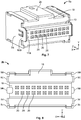
socket module 2a has twowall sections 4, 4' which run essentially in parallel with a plug-direction Z and a length direction X of the plug-element 1a. Thewall sections 4, 4' are distanced from each other in a width direction Y of the plug-element and form areceptacle 5 between them. The width direction Y runs perpendicularly to length direction X as well as to the plug-direction Z. - The
wall section 4 is provided with a guidingorgan 6 and a latching organ comprising a latchingelement 7 in the form of a nib and a latching element 7' in the form of a latching recess which are adapted to snap behind a counter-latching element (not shown) of a mating plug-element (not shown). The wall section 4' is further provided with a guidingorgan 8 in form of a notch extending along the plug-in direction Z. Outer edges (not yet shown) of thewall sections 4, 4' and a base (not yet shown) of thesocket module 2a are provided with fixingelements modules 3a to thesocket module 2a. The fixingelements 9a to 9d are formed as lugs which engage withcounter-fixing elements outer rim 11 of the mountingmodules 3a, respectively. Thecounter-fixing elements 10a to 10d are formed as recesses. A further fixingelement 9e on the lateral edge of the base (not yet shown) of thesocket module 2a is formed as a protrusion and interacts with anothercounter-fixing element 10e which is formed at awall portion 12 of the mountingmodules 3a. - The
wall portions 12 of the mountingmodules 3a close an open lateral side, i.e. a recess (not yet shown) of thesocket module 2a, respectively.Upper rims 13 of thewall portions 12 of the mountingmodules 3a andfront edges 14, 14', respectively, of thewall sections 4, 4' of thesocket module 2a together define aplug opening 15 through which thereceptacle 5 is accessible. - Further, the mounting
modules 3a are each provided with a mountingsection 16a which protrudes from the mountingmodules 3a and therefore from theplug element 1 against the plug-direction Z. A mountingorgan 17a is formed at each of the mountingsections 16a. The mountingorgan 17a is adapted to engage with a substrate (not yet shown) in order to attach the plug-element 1a to a substrate which may be a PCB of an electronic device. -
Fig. 2 shows the plug-element 1a in another schematic perspective view. Thebase 18 of thesocket module 2a is on its backside provided with aprotuberance 19 which protrudes from the backside against the plug-direction Z. Contact supports 20 extend through theprotuberance 19. Theprotuberance 19 helps to form and reinforce the contact supports 20 such that they may rigidly and securely hold electrical contact elements (not yet shown). The mountingsections 16a at the mountingmodules 3a, respectively, flank theprotuberance 19 at its lateral sides (not yet shown). - Further, at the backside of the base 18 in the area of the
protuberance 19, thesocket module 2a is provided with anindentation 21. Theindentation 21 may serve as a coding keyway facilitating handling the plug-element as well as an access facilitating a detachment of thecounter-fixing element 10e from the fixingelement 9e. -
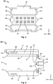
Fig. 3 is a back view of thesocket module 2a shown inFig. 1 and 2 . Here it becomes evident that the fixingelements 9a to 9e laterally protrude from theside walls 4, 4' and thebase 18, respectively, in parallel to the length direction X. -
Fig. 4 is a schematic side view of the socket module shown inFig. 3 . Here it becomes evident that the fixingelements side walls 4, 4' are formed atlateral edges 22, 22', of theside walls 4, 4', respectively. The fixingelements base 18. - Between opposing
inner sides wall sections 4, 4', respectively, and a bottom 25 of thereceptacle 5, arecess 26 is formed. Thesocket module 2a is laterally open through therecess 26 in parallel to the length direction X. In other words, side walls closing thereceptacle 5 in the length direction X are missing.
Further, acontact support area 27 is formed at the bottom 25 of thereceptacle 5. Thecontact support area 27 slightly protrudes from the bottom 25 in the plug-direction Z. -
Fig. 5 is a schematic front view of thesocket module 2a shown inFigs. 3 and 4 .Fig. 5 allows a view straight into thereceptacle 5 formed between the opposinginner sides wall sections 4, 4'. - The contact supports 20 are arranged in two
rows 28, 28' which run in parallel with the length direction X. Each of therows 28, 28' of contact supports 20 is provided withidentifiers 29 in the form of numbers which help to identify the individual contact supports 20 in order correctly equip the contact supports 20 with electrical contacts (not yet shown). -
Figs. 6 and7 analogously toFigs. 1 and 2 show a plug-element 1b according to an embodiment of the present invention. Indistinct from the plug-element 1a, the plug-element 1b is provided with asocket module 2b, which is elongated in the length direction X relative to thesocket module 2a. Like the plug-element 1a, the plug-element 1b is provided with mountingmodules 3a. -
Figs. 8 to 10 analogously toFigs. 3 to 5 show thesocket module 2b in a schematic back view, side view and front view, respectively. In comparison to thesocket module 2a, thesocket module 2b is elongated in the length direction X. Therows 28, 28' each comprise ten contact supports 20. Hence, thesocket module 2b provides twenty contact supports 20. - The
wall section 4 of themodule 2b is provided with the guidingorgan 6, running centrally with respect to thereceptacle 5 in the plug-direction Z. Further guiding organs 6' in the form of notches extending in parallel with the plug-direction Z, are provided in the vicinity of the lateral side or side face 23 at the lateral edges 22, 22' on thewall sections 4, 4', respectively, of thesocket module 2b. - As a further distinction from the
socket module 2a, thecoding organ 8 having the form of a notch extending in parallel to the plug-direction Z is located differently to thenotch 8 on the wall section 4' of thesocket module 2a. Hence, even ifsocket modules respective receptacle 5 would still provide a proper distinction between thesocket modules different guiding organs 6, 6' andcoding organs 8. -
Fig. 11 is a schematic side view of the mountingmodule 3a. The mountingmodule 3a may be formed of metal sheet material which could be shaped in a stamping process, for example, in order to obtain the desired design. - The mounting
module 3a has a thickness d. The thickness d may be selected such, that it is less than a length of the fixingelements 9a to 9e measured in the length direction X. Thus, the thickness of the mountingmodule 3a does not add to the overall length of the plug-element
Fig. 12 shows the mountingmodule 3a in a schematic front view. A middle axis W of the mountingmodule 3a extends in parallel to the plug-direction Z. The mountingorgan 17a on the mountingsection 16a of the mountingmodule 3a is arranged coaxially to the middle axis W such, that a mounting direction M running towards the plug-direction Z and the middle axis W run in parallel. Hence, a mounting angle α between the axis W and the mounting direction M is 180°. The mountingsection 16a with the mountingorgan 17a is thereby adapted to be used for 180° THT mounting or to be soldered to the substrate. - Further, the mounting
module 3a comprises a holdingsection 30 which includes thecounter fixing elements 10a to 10b and thewall portion 12. The holdingsection 30 enables affixing securely the mountingmodule 3a to thesocket module -
Fig. 13 is a schematic front view of a mountingmodule 3b according to another embodiment of the present invention. In distinction from the mountingmodule 3a, the mountingmodule 3b is provided with a mountingsection 16b having a mountingorgan 17b which are designed such, that they enable a 90° THT mounting or soldering of the mountingmodule 3b. The middle axis W of the mountingmodule 3b runs in parallel to the plug-direction Z. The mounting direction M of the mountingmodule 3b runs in parallel to the width direction Y. Thus, a mounting angle α' between the middle axis W and the mounting direction M of the mountingmodule 3b is 90°. - The holding
section 30 of the mountingmodule 3b is designed similarly to the holding section of the mountingmodule 3a. The mountingmodules socket modules element -
Fig. 14 is a schematic front view of a mounting module 3c according to another embodiment of the present invention. The holdingsection 30 of the mounting module 3c is similar to the holdingsection 30 of the mountingmodules -
Fig. 15 is a schematic front view of a mountingmodule 3d according to another embodiment of the present invention. Similarly to the holdingsections 30 of the mountingmodule 3a to 3c, the holdingsection 30 of the mountingmodule 3d is adapted to be affixed to thesocket modules socket modules section 30. - A mounting
section 16d providing a mountingorgan 17d of the mountingmodule 3d is shaped such, that the mountingmodule 3d is adapted for a 90° press-fit mounting on the substrate. The middle axis W of the mountingmodule 3d runs in parallel with the plug-direction Z. The mounting direction M defined by the mountingsection 16d runs in parallel with the width direction Y. Hence, the middle axis W and the mounting direction M define a mounting angle α' of 90° between each other. -
Fig. 16 is a schematic front view of a mounting section 16 having a mountingorgan 17e which may be provided to a mountingmodule 3a to 3d according to an embodiment of the present invention. The mountingorgan 17e may be used, for example, in order to affix the mountingsection 16e at a mounting angle α of 90° with respect to a substrate. -
Fig. 17 is a schematic cross-sectional view of the mountingsection 16e shown inFig. 16 along the cross-sectional line A-A illustrated therein. As can be seen inFig. 17 , the mountingorgan 17e has the form of a lug which has a curved cross-section. Thereby, the mountingorgan 17e may be inserted into a through-hole of a substrate, for example, in order to hold the mountingsection 16e tightly in a positive, form-fit, and/or traction fit manner. -
Fig. 18 is a schematic front view of a mountingsection 16f which is provided with a mountingorgan 17f. The mountingsection 16f could be implemented at any mountingmodule section 16f is adapted for through-hole mounting on a substrate at a mounting angle α of 180° with respect to the substrate since both the mounting direction M and the middle axis W of the mountingsection 16f run in parallel to the plug-in direction. -
Fig. 19 is a schematic cross-sectional view of the mountingsection 16f shown inFig. 18 along the cross-sectional line B-B illustrated therein. As can be seen inFig. 19 , the mountingorgan 17f on the mountingsection 16f has the form of a kink which allows affixing of a mountingmodule section 16f to a substrate in a positive, form-fit and/or traction fit manner. -
Fig. 20 is a schematic front view of a mountingsection 16g which is provided with a mountingorgan 17g. The mountingsection 16g may be formed at any mountingmodule section 16g both extend in parallel to the plug-in direction. Hence, the middle axis W and the mounting direction M define a mounting angle α of 90° between each other. -
Fig. 21 is a schematic side view of the mountingsection 16g shown inFig. 20 . As can be seen inFig. 21 , the mountingorgan 17g on the mountingsection 16g is hook-shaped such, that it may be inserted into a through-hole or any attaching facility on a substrate in order to firmly hold a mountingmodule section 16g in a form-fit, positive fit and/or traction fit manner. -
Fig. 22 is a schematic perspective view of an exemplary plug-element 1c which does not form part of the present invention. The plug-element 1c comprises a socket module 2c and two mountingmodules 3e. InFig. 22 , the plug-element 1c is illustrated in a pre-assembled state P, wherein the mountingmodules 3e are arranged to be affixed to the socket module 2c by pushing them towards the socket module 2c in the length direction X such, that fixingelements 9f to 9h having the form of cylindrical studs jut intocounter-fixing elements 10f to 10h, respectively of the mountingmodule 3e which have the form of through-holes. The fixingelements 9f to 9h are provided on asidewall 31, the socket module 2c.
Two of thesidewalls 31 and thewall sections 4 and 4' of thesocket module 1c form thereceptacle 5 and the plug opening 15 to thereceptacle 5 of thesocket module 1c. Thereceptacle 5 is provided withlatching elements 7, 7' formed at thewall section 4 and guidingorgans 6 as well as acoding organ 8 having the form of notches running parallel to the plug-direction on the wall section 4' of thesocket module 1c. -
Fig. 23 is a schematic perspective view of a detail of the plug-element 1c in an assembled state Q. In the assembled stat Q, the fixingelements 9f to 9h jut through thecounter fixing elements 10f to 10h, respectively. - The
counter fixing elements hole 32 and alug 33. Thelug 33 of thecounter fixing element 10f extends in parallel to the width direction Y such, that the fixingelement 9f is jammed and therefore firmly held in the direction Y. Thelug 33 of thecounter fixing element 10g extends in the plug-direction Z such, that the fixingelement 9g is jammed therefore firmly held in the plug-direction Z. - Further, in the assembled state Q, the fixing
element 9h having a slightly smaller diameter than thecounter fixing element 10h still allows for a movement of the mountingmodule 3e in the length direction X. Thereby, any production tolerance of the socket module 2c and the mountingmodule 3e may be compensated. -
Fig. 24 is a schematic perspective view of the plug-element 1c shown inFigs. 22 and 23 in a joined state R. In the joined state R, the fixingelement 9h has been treated such that it sits within thecounter fixing element 10h in a form-fit manner. For example, the fixingelement 9h may be treated, for example, in an ultrasonic or laser welding process. The fixingelement 9h may also be designed as a rivet. In the joint state R, the fixingelement 9h may protrude out of thecounter fixing element 10h such, that it overlaps with the mountingmodule 3e in order to prevent any movement of the mountingmodule 3e with respect to the socket module 2c in the length direction X. Hence, in the joined state R, the mountingmodule 3e and the socket module 2c are joined together such, that they are firmly mounted to each other and form the plug-element 1c.
Fig. 25 is a schematic side view of the plug-element 1c comprising the socket module 2c and the mountingmodule 3e. As can be seen inFig. 25 , the mountingmodule 3e has two branches 33'. On these branches 33', thecounter fixing elements 10f to 10h are arranged such, that they form an isosceles triangle having a square angle between the legs a. The branches 33' have a breadth E. Thecounter fixing elements 10f to 10h have a diameter D. In each case, an overlap O is provided with which themounting module 3e may overlap the edges of thesidewalls 31 of the socket module 2c such, that the socket module 2c may be held in a proper distance to the substrate in order to enable enough freedom for SMT, THT press-fit and/or soldering. -
Fig. 26 is a detail of a schematic perspective view of anexemplary plug element 1d which does not form part of the present invention. Thesidewall 31 of thesocket module 2d is provided with fixingelements 9h to 9k having the form of studs which protrude laterally from thesidewall 31 in parallel to the length direction X.
The fixingelements 9h to 9k jut throughcounter fixing elements 10h to 10k formed at the mountingmodule 3f. The fixingelements element 9i. Thecounter fixing elements fixing elements hole 32 and alug 33. Thelugs 33 of thecounter fixing element lugs 33 of thecounter fixing elements elements section 30 of the mountingmodule 3f comprising thecounter fixing elements 10h to 10k at thesocket module 2d.
The fixingelement 9i has a smaller diameter than the fixingelements elements section 30. The fixingelement 9i may be treated by ultrasonic or laser welding in order to deform it such, that it overlaps with the mountingmodule 3f in the length direction X in order to tie themounting module 3f to thesocket module 2d such, that they are inextricably linked with each other.
The mountingmodule 3f is provided with two mountingsections organs sections section 30 of the mountingmodule 3f in different directions under an angle of 90° between each other. Hence, by pivoting the mountingmodule 3f around the fixingelement 9i and/or flipping the mountingmodule 3f, thedifferent mounting sections element 1d to the substrate with respect to a desired mounting angle between the plug-element 1d and a substrate as well as a desired mounting technology.
The mountingsection 16f is provided with a mountingorgan 17f having the form of a lug which may be used for through-hole mounting or soldering, for example. The two mountingorgans 17f' of the mountingsection 16f' are shaped as resiliently displaceable hooks which oppose each other and thereby enable snapping the mountingsection 16f' into a through-hole on a substrate in order to enable a form-fit and/or traction fit.
Further, thesocket module 2d is provided with amark 34 having the form of an arrow which may indicate the mounting direction M of the plug-element 1d which is selected according to the rotary position of the mountingmodule 3f. As can be seen inFig. 26 , the selected rotary position of the mountingmodule 3f is a 90°-mounting because when using the mountingorgan 17f, the mounting direction M and the plug-direction Z define a mounting angle α of 90°.
Fig. 27 is a schematic perspective view of a detail of the plug-element 1d shown inFig. 26 . In distinction from the arrangement of thesocket module 2d and the mountingmodule 3f shown inFig. 26 , thesocket module 2d and the mountingmodule 3f illustrated inFig. 27 are arranged such that the mountingorgans 17f' of the mountingsection 16f' allow for a mounting of the plug-element 1c under a mounting angle α of 180° with respect to the substrate. In other words, the mounting angle α between the plug-direction Z predefined by thereceptacle 5 and the mounting direction M given by the mountingsection 16f' is 180°. -
Fig. 28 is a schematic front view of anexemplary mounting module 3g which does not form part of the present invention. The mountingmodule 3g is provided withcounter fixing elements 10k to 10p in the form of through-holes. Thecounter fixing elements counter fixing element 10p which may be used as a pivot point for pivoting the mountingmodule 3g on a respective fixing element (not shown) adapted to affix the mountingmodule 3g in different rotary positions in order to enable different mounting angles α, α'. - The mounting
module 3g is provided with a mountingsection 16g which comprises a mountingorgan 17g in the form of a slit which may be used to attach the mountingmodule 3g to the substrate, e.g. by letting a bracket of the substrate (not shown) engage with the mountingorgan 17g. -
Fig. 29 is a schematic side view of the mountingmodule 3g shown inFig. 28 . The mountingmodule 3g has a thickness d which may be selected such that it does not add to the length of a plug-element 1a to 1d as explained above. -
Fig. 30 is a schematic front view of several mountingmodules 3g which are combined as areel 50. By attaching the mountingmodules 3g to each other the form thereel 50, the mountingmodules 3g may be easily fed to an automatic manufacturing or assembling device which assembles theplug elements 1a to 1d by joining thesocket modules 2a to 2d with the mountingmodules 3a to 3g. -
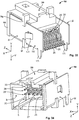
Fig. 31 is a schematic perspective view of a plug-element 1e according to an embodiment of the present invention. The plug-element 1e comprises asocket module 2e and two mountingmodules 3h. The contact supports 20 in theprotuberance 19 in the backside of thebase 18 of thesocket module 2e are each equipped with anelectrical contact 35 in the form of a press-fit pin which is press-fitted into therespective contact support 20.
Thesocket module 2e is equipped with fixingelements 9q to 9s on the lateral side faces 22, 22' of thewall sections 4, 4', respectively. The fixingelements wall sections 4, 4' in the vicinity of their respective front edges 14, 14'. - The mounting
module 3h is slid underneath the fixingelements 9q to 9s in the plug-direction Z such that the fixingelements counter fixing elements 10q and 10r in the form of notches on the side faces of the mountingmodules 3h. The front edge of the mountingmodule 3h is slid underneath the fixing element 9s. Hence, the mountingmodule 3h is firmly held at itsholding section 30 by thesocket module 2e. - Further, the mounting
module 3h is provided with a mountingsection 16h which comprises a mountingorgan 17h in the form of a pin protruding from the mountingmodule 3h in the mounting direction M against the plug-direction Z and anauxiliary mounting organ 17h' in the form of a latch laterally protruding from the mountingmodule 3h such that it allows for latching the plug-element 1e at a substrate or holder. The mountingorgan 17h is arranged such that it allows for a mounting angle α between the plug-direction Z and the mounting direction M of 180°. -
Fig. 32 is another schematic perspective view of the plug-element 1e illustrated inFig. 31. Fig. 32 allows an inspection of thereceptacle 5 through the plug opening 15 of the plug-element 1e. Within thereceptacle 5, theelectrical contacts 20 protrude from thebase 18 of thesocket module 2e in the plug direction Z. Thewall section 4 of thesocket module 2e is provided with a guidingorgan 6 having the form of a notch running parallel to the plug-direction Z and a latchingorgan 7 in the form of a catch as well as a latching organ 7' in the form of a through-hole which are adapted to engage with a mating plug-element (not shown). The wall section 4' of thesocket module 2e is provided with guiding organs 6' in the vicinity of the lateral edges 22 and 22' of thewall sections 4 and 4', respectively, in the form of notches running in the plug-direction Z. Acoding organ 8 in the form of a notch running in the plug-direction Z is also provided on the wall section 4'. - Further, the
wall sections 4 and 4' as well as theportions 12 of the mountingmodules 3h define a contour of thereceptacle 5. Thesocket module 2e is not provided with lateral side walls, the mountingmodules 3h close the respective recesses left open at the sides of thesocket module 2e in the length direction X. -
Fig. 33 is a schematic perspective view of the plug-element 1e according to another embodiment of the present invention. The plug-element 1e comprises thesocket module 2e previously known fromFigs. 31 and 32 and amounting module 3i. In distinction to the mountingmodule 3h, the mountingmodule 3i is provided with a mountingsection 16i which comprises a mountingorgan 17i and a mountingorgan 17i'. The mountingorgan 17i' is similar to the mountingorgan 17h', of the mountingmodule 3h. - The mounting
organ 17i in the form of a pin is arranged such that it protrudes from the mountingmodule 3i perpendicularly to the plug-direction Z and thereby defines a mounting direction M of the plug-element 1e which allows for a 90°-mounting of the plug-element 1e with respect to the substrate. In other words, the mounting angle α between the plug-direction Z and the mounting direction M is 90°. -
Fig. 34 is another schematic perspective view of the plug-element 1e illustrated inFig. 30 .Fig. 34 allows for a view into thereceptacle 5 of the plug-element 1e. Within thereceptacle 5, theelectrical contact elements 35 are arranged in tworows 28, 28' in theircontact support area 27 on the bottom 25 of thereceptacle 5 of the plug-element 1e. -
Fig. 35 is a schematic cross-sectional view taken along a plane spreading parallely to the width direction Y and the plug-direction Z through theelectrical contacts 35 in their respective contact supports 20 of therows 28 and 28', respectively. Theinner sides wall sections 4, 4', respectively, of thesocket module 2e and thewall portions 12 of the mountingmodules 3i define between themselves thereceptacle 5. Hence, the holdingsection 30 of the mountingmodules 3i forms a part of thereceptacle 5. - Further, in
Fig. 35 it becomes evident that the mounting angle α' between the mounting direction M defined by the mountingorgan 17i and the plug-direction Z allows for a 90°-mounting of the plug-element 1e with respect to the substrate.Fig. 36 is a schematic perspective view of the plug-element 1e which is mounted to asubstrate 100 in the form of a PCB. The plug-element 1e is mounted to thesubstrate 100, with a mounting angle α' of 90°. The mountingorgans 17i of the mountingmodules 3i jut into respective mountingelements 101 in the form of cavities in thesubstrate 100. Further, theelectrical contacts 35 protruding from the plug-element 1e against the plug-direction Z are angled such that their rear ends which run parallel to the mounting direction M are sitting within respective mating contact supports 102 in the form of through-holes for a press-fit in thesubstrate 100. - Deviations from the above described embodiments of the plug-
elements - The
socket modules wall sections 4, 4' being equipped however desired with guidingorgans 6, 6', latchingelements 7, 7',coding organs 8, fixingelements 9a to 9s, front edges 14, 14', bases 18,protuberances 19, contact supports 20,indentations 21, lateral edges 22, 22', side faces 23,inner sides bottoms 25 of thereceptacles 5, recesses 26 between thewall sections 4, 4',contact support areas 27, rows of contact supports 28, 28',identifiers 29, and marks 34 however desired for forming areceptacle 5, an opening to thereceptacle 15 and the desired possibilities for attaching at least one of the mountingmodules 3a-3i to thesocket modules 2a-2e. - The mounting
modules 3a - 3d, 3h, 3i may be shaped as desired in order to have holdingsections 30 which may be attached to thesocket modules modules 3a - 3d, 3h, 3i form a part of thereceptacles 5. In order to affix the mountingmodules 3a - 3d, 3h, 3i to thesocket modules 2a-2e, they may be provided withcounter fixing elements 10a-10s,outer rims 11,wall portions 12,upper rims 13, mountingsections 16a-16i, mountingorgans 17a-17i, through-holes 32, locks 33 and branches 33' in whatever shape and form desired in order to attach the mountingmodules 3a - 3d, 3h, 3i to thesocket modules elements substrate 100 in a desired way and angle α, α'. - It should be understood that the angles α, α' are not limited to mounting angles of 180° and 90° but may be any desired angle. Further, the mounting
modules 3a - 3d, 3h, 3i may
be provided with as manycounter fixing elements 10a-10s and mountingsections 16a-16i in order to enable multiple ways of mounting the plug-elements 1a-1e with a single combination of a type of selectedsocket module 2a-2e and atype mounting module 3a-3i.
Claims (7)
- Electrical plug-element (1a, 1b, 1e) comprising
at least one socket module (2a, 2b, 2e) with a receptacle (5) for a mating plug-element, the receptacle (5) opens towards a plug-direction (Z) of the plug-element (1a, 1b, 1e), is formed between at least two wall sections (4, 4') of the socket module (2a, 2b, 2e) which extend essentially in parallel to a length direction (X) of the plug-element (1a, 1b, 1e), and accommodates at least one contact support area (27) which extends along the length direction (X) and at least partially faces into the plug-direction (Z), wherein
the receptacle (5) is laterally open through at least two recesses (26) each extending along a width direction (Y) of the socket module (2a, 2b, 2e) between the at least two wall sections (4, 4'), the width direction (Y) extends perpendicularly to the length direction (X) and the plug-direction (Z), wherein the at least one contact support area (27) is located at a bottom portion (25) of the receptacle (5), the bottom portion (25) facing into the plug-direction (Z), and wherein the recesses (26) extend down to the bottom portion (25) and/or essentially along a distance measured in parallel to the width direction (Y) between the wall sections (4, 4'), characterised by at least two mounting modules (3a-3d, 3h, 3i) each having a holding section (30) attached to a lateral side of the socket module (2a, 2b, 2e), the lateral side extending essentially in parallel to the plug-direction (Z), and a mounting section (16a-16d, 16h, 16i) providing a mounting organ (17a-17d, 17h, 17i) adapted to be fastened to a substrate (100), wherein the mounting modules (3a-3d, 3h, 3i) at least partially close the recesses (26). - Plug-element (1a, 1b, 1e) according to claim 1, characterised in that the holding section (30) of each of the mounting modules (3a-3d, 3h, 3i) comprises a wall portion (12) which at least partially closes the recess (26) of the socket module (2a, 2b, 2e).
- Plug-element (1a, 1b, 1e) according to claim 1 or 2, characterised in that a lateral edge (22, 22') of each of the wall sections (4, 4') and/or of a base (18) of the socket module (2a-2i) is provided with at least one fixing element (9a-9s) for affixing each of the mounting modules (3a-3d, 3h, 3i) at the socket module (2a, 2b, 2e).
- Plug-element (1a, 1b, 1e) according to any one of claims 1 to 3, characterised in that the holding section (30) of each of the mounting modules (3a-3d, 3h, 3i) is provided with at least one counter fixing element (10a-10s) interacting with the at least one fixing element (9a-9s).
- Plug-element (1a, 1b, 1e) according to one of claims 1 to 4, characterised in that a thickness (d) of the holding section (30) of at least one of the mounting modules (3a-3d, 3h, 3i) is below 0,5 mm.
- Plug-element (1a, 1b, 1e) according to one of claims 1 to 5, characterised in that the socket module (2a, 2b, 2e) is formed of plastic material and/or the mounting modules (3a-3d, 3h, 3i) are formed of metal sheet material.
- Plug-element (1a, 1b, 1e) according to one of claims 1 to 6, characterised in that the at least one contact support area (27) comprises at least one row (28, 28') of contact supports, the at least one row (28, 28') of contact supports (20) runs longitudinally essentially in parallel to the length direction (X).
Applications Claiming Priority (2)
| Application Number | Priority Date | Filing Date | Title |
|---|---|---|---|
| IT000241A ITVI20100241A1 (en) | 2010-09-01 | 2010-09-01 | MODULAR ELECTRICAL CONNECTOR |
| PCT/EP2011/063938 WO2012028439A1 (en) | 2010-09-01 | 2011-08-12 | Modular electrical connector |
Publications (2)
| Publication Number | Publication Date |
|---|---|
| EP2612401A1 EP2612401A1 (en) | 2013-07-10 |
| EP2612401B1 true EP2612401B1 (en) | 2018-01-03 |
Family
ID=43606423
Family Applications (1)
| Application Number | Title | Priority Date | Filing Date |
|---|---|---|---|
| EP11743076.9A Not-in-force EP2612401B1 (en) | 2010-09-01 | 2011-08-12 | Modular electrical connector |
Country Status (5)
| Country | Link |
|---|---|
| EP (1) | EP2612401B1 (en) |
| AR (1) | AR082808A1 (en) |
| IT (1) | ITVI20100241A1 (en) |
| TW (1) | TWI528652B (en) |
| WO (1) | WO2012028439A1 (en) |
Families Citing this family (2)
| Publication number | Priority date | Publication date | Assignee | Title |
|---|---|---|---|---|
| DE102015008040B4 (en) * | 2015-06-23 | 2022-03-24 | Yamaichi Electronics Deutschland Gmbh | MQS connector and method of manufacturing an MQS connector |
| CN109634034B (en) * | 2018-12-27 | 2023-09-05 | 成都极米科技股份有限公司 | Drawer push-pull structure projector and assembling method thereof |
Citations (5)
| Publication number | Priority date | Publication date | Assignee | Title |
|---|---|---|---|---|
| US5241451A (en) * | 1992-09-01 | 1993-08-31 | The Whitaker Corporation | Modular electronic assemblies using compressible electrical connectors |
| US5613877A (en) * | 1995-11-02 | 1997-03-25 | Molex Incorporated | Electric connector boardlock |
| EP1587170A1 (en) * | 2004-04-12 | 2005-10-19 | Sumitomo Wiring Systems, Ltd. | A connector and a method of mounting it |
| US20060009091A1 (en) * | 2004-07-12 | 2006-01-12 | Kabushiki Kaisha Tokai-Rika-Denki-Seisakusho | Surface-mounted connector |
| EP1947739A1 (en) * | 2005-11-04 | 2008-07-23 | Tyco Electronics AMP K.K. | Holding member, packaging structure, and electronic component |
Family Cites Families (1)
| Publication number | Priority date | Publication date | Assignee | Title |
|---|---|---|---|---|
| TWM364331U (en) * | 2009-02-23 | 2009-09-01 | Hon Hai Prec Ind Co Ltd | Electrical connector |
-
2010
- 2010-09-01 IT IT000241A patent/ITVI20100241A1/en unknown
-
2011
- 2011-08-12 WO PCT/EP2011/063938 patent/WO2012028439A1/en not_active Ceased
- 2011-08-12 EP EP11743076.9A patent/EP2612401B1/en not_active Not-in-force
- 2011-08-31 AR ARP110103164A patent/AR082808A1/en unknown
- 2011-08-31 TW TW100131353A patent/TWI528652B/en not_active IP Right Cessation
Patent Citations (5)
| Publication number | Priority date | Publication date | Assignee | Title |
|---|---|---|---|---|
| US5241451A (en) * | 1992-09-01 | 1993-08-31 | The Whitaker Corporation | Modular electronic assemblies using compressible electrical connectors |
| US5613877A (en) * | 1995-11-02 | 1997-03-25 | Molex Incorporated | Electric connector boardlock |
| EP1587170A1 (en) * | 2004-04-12 | 2005-10-19 | Sumitomo Wiring Systems, Ltd. | A connector and a method of mounting it |
| US20060009091A1 (en) * | 2004-07-12 | 2006-01-12 | Kabushiki Kaisha Tokai-Rika-Denki-Seisakusho | Surface-mounted connector |
| EP1947739A1 (en) * | 2005-11-04 | 2008-07-23 | Tyco Electronics AMP K.K. | Holding member, packaging structure, and electronic component |
Also Published As
| Publication number | Publication date |
|---|---|
| WO2012028439A1 (en) | 2012-03-08 |
| EP2612401A1 (en) | 2013-07-10 |
| AR082808A1 (en) | 2013-01-09 |
| ITVI20100241A1 (en) | 2012-03-02 |
| TWI528652B (en) | 2016-04-01 |
| TW201230517A (en) | 2012-07-16 |
Similar Documents
| Publication | Publication Date | Title |
|---|---|---|
| KR101364231B1 (en) | Connector | |
| KR102131071B1 (en) | Connector assembly with receptacle carriers | |
| US6109952A (en) | Terminal connector assembly | |
| KR100961592B1 (en) | A panel having a front surface and a rear surface; | |
| EP1235303B1 (en) | A connector terminal and a method for producing the same | |
| EP1089385A2 (en) | Electrical connector with electrical shield having latch and mounting arms | |
| US12489241B2 (en) | Connection strip and method of manufacturing the connection strip | |
| JP3396183B2 (en) | Connector with ground pin for PCB | |
| EP1107373B1 (en) | Press-fit connector | |
| WO2009010704A1 (en) | An electrical unit | |
| CN117121304A (en) | Plug connector insert and method of assembling the same | |
| CN119050712A (en) | Plug-in connector | |
| JP2689325B2 (en) | Zero insertion force electrical connector and terminal | |
| US7059915B1 (en) | Panel mounted modular jack terminated to a circuit board | |
| EP0507166B1 (en) | Grounding electrical connector | |
| EP2612401A1 (en) | Modular electrical connector | |
| EP1839373B1 (en) | Surface mount connector assembly | |
| KR102005586B1 (en) | Connector module | |
| TWI430514B (en) | Electrical connector | |
| KR20090085611A (en) | connector | |
| US7303449B2 (en) | Spring bushing for miniature plug-in connectors having contact spring with insertion depth equal to or less than insertion width | |
| JP2007128875A (en) | Electrical connector | |
| JP6406705B2 (en) | Contacts, receptacles and connectors | |
| KR19980024412A (en) | Connector for Flexible Circuit Board | |
| JP2005285352A (en) | Bottom entry type connector |
Legal Events
| Date | Code | Title | Description |
|---|---|---|---|
| PUAI | Public reference made under article 153(3) epc to a published international application that has entered the european phase |
Free format text: ORIGINAL CODE: 0009012 |
|
| 17P | Request for examination filed |
Effective date: 20130328 |
|
| AK | Designated contracting states |
Kind code of ref document: A1 Designated state(s): AL AT BE BG CH CY CZ DE DK EE ES FI FR GB GR HR HU IE IS IT LI LT LU LV MC MK MT NL NO PL PT RO RS SE SI SK SM TR |
|
| RIN1 | Information on inventor provided before grant (corrected) |
Inventor name: SCHMITT, THOMAS Inventor name: FRANK, OLIVER Inventor name: NEUBERT, LUTZ Inventor name: THOMAS, SARAH Inventor name: LOVERA, IVO Inventor name: FERTIG, JOCHEN Inventor name: GENTA, ALESSANDRO Inventor name: DIETRICH, WILLI Inventor name: BRICCARELLO, ALESSANDRO Inventor name: SPIELVOGEL, MICHAEL |
|
| DAX | Request for extension of the european patent (deleted) | ||
| 17Q | First examination report despatched |
Effective date: 20140919 |
|
| RAP1 | Party data changed (applicant data changed or rights of an application transferred) |
Owner name: TYCO ELECTRONICS AMP ITALIA S.R.L. Owner name: TE CONNECTIVITY GERMANY GMBH |
|
| GRAP | Despatch of communication of intention to grant a patent |
Free format text: ORIGINAL CODE: EPIDOSNIGR1 |
|
| RIC1 | Information provided on ipc code assigned before grant |
Ipc: H01R 13/506 20060101AFI20170628BHEP Ipc: H01R 12/70 20110101ALI20170628BHEP Ipc: H01R 43/16 20060101ALI20170628BHEP Ipc: H01R 12/71 20110101ALN20170628BHEP Ipc: H01R 12/72 20110101ALN20170628BHEP Ipc: H01R 27/00 20060101ALI20170628BHEP Ipc: H01R 13/658 20110101ALN20170628BHEP |
|
| INTG | Intention to grant announced |
Effective date: 20170713 |
|
| GRAS | Grant fee paid |
Free format text: ORIGINAL CODE: EPIDOSNIGR3 |
|
| GRAA | (expected) grant |
Free format text: ORIGINAL CODE: 0009210 |
|
| AK | Designated contracting states |
Kind code of ref document: B1 Designated state(s): AL AT BE BG CH CY CZ DE DK EE ES FI FR GB GR HR HU IE IS IT LI LT LU LV MC MK MT NL NO PL PT RO RS SE SI SK SM TR |
|
| REG | Reference to a national code |
Ref country code: GB Ref legal event code: FG4D |
|
| REG | Reference to a national code |
Ref country code: CH Ref legal event code: EP Ref country code: AT Ref legal event code: REF Ref document number: 961088 Country of ref document: AT Kind code of ref document: T Effective date: 20180115 |
|
| REG | Reference to a national code |
Ref country code: IE Ref legal event code: FG4D |
|
| REG | Reference to a national code |
Ref country code: DE Ref legal event code: R096 Ref document number: 602011044723 Country of ref document: DE |
|
| REG | Reference to a national code |
Ref country code: NL Ref legal event code: MP Effective date: 20180103 |
|
| REG | Reference to a national code |
Ref country code: LT Ref legal event code: MG4D |
|
| REG | Reference to a national code |
Ref country code: AT Ref legal event code: MK05 Ref document number: 961088 Country of ref document: AT Kind code of ref document: T Effective date: 20180103 |
|
| PG25 | Lapsed in a contracting state [announced via postgrant information from national office to epo] |
Ref country code: NL Free format text: LAPSE BECAUSE OF FAILURE TO SUBMIT A TRANSLATION OF THE DESCRIPTION OR TO PAY THE FEE WITHIN THE PRESCRIBED TIME-LIMIT Effective date: 20180103 |
|
| REG | Reference to a national code |
Ref country code: FR Ref legal event code: PLFP Year of fee payment: 8 |
|
| PG25 | Lapsed in a contracting state [announced via postgrant information from national office to epo] |
Ref country code: ES Free format text: LAPSE BECAUSE OF FAILURE TO SUBMIT A TRANSLATION OF THE DESCRIPTION OR TO PAY THE FEE WITHIN THE PRESCRIBED TIME-LIMIT Effective date: 20180103 Ref country code: HR Free format text: LAPSE BECAUSE OF FAILURE TO SUBMIT A TRANSLATION OF THE DESCRIPTION OR TO PAY THE FEE WITHIN THE PRESCRIBED TIME-LIMIT Effective date: 20180103 Ref country code: CY Free format text: LAPSE BECAUSE OF FAILURE TO SUBMIT A TRANSLATION OF THE DESCRIPTION OR TO PAY THE FEE WITHIN THE PRESCRIBED TIME-LIMIT Effective date: 20180103 Ref country code: LT Free format text: LAPSE BECAUSE OF FAILURE TO SUBMIT A TRANSLATION OF THE DESCRIPTION OR TO PAY THE FEE WITHIN THE PRESCRIBED TIME-LIMIT Effective date: 20180103 Ref country code: FI Free format text: LAPSE BECAUSE OF FAILURE TO SUBMIT A TRANSLATION OF THE DESCRIPTION OR TO PAY THE FEE WITHIN THE PRESCRIBED TIME-LIMIT Effective date: 20180103 Ref country code: NO Free format text: LAPSE BECAUSE OF FAILURE TO SUBMIT A TRANSLATION OF THE DESCRIPTION OR TO PAY THE FEE WITHIN THE PRESCRIBED TIME-LIMIT Effective date: 20180403 |
|
| PG25 | Lapsed in a contracting state [announced via postgrant information from national office to epo] |
Ref country code: IS Free format text: LAPSE BECAUSE OF FAILURE TO SUBMIT A TRANSLATION OF THE DESCRIPTION OR TO PAY THE FEE WITHIN THE PRESCRIBED TIME-LIMIT Effective date: 20180503 Ref country code: GR Free format text: LAPSE BECAUSE OF FAILURE TO SUBMIT A TRANSLATION OF THE DESCRIPTION OR TO PAY THE FEE WITHIN THE PRESCRIBED TIME-LIMIT Effective date: 20180404 Ref country code: PL Free format text: LAPSE BECAUSE OF FAILURE TO SUBMIT A TRANSLATION OF THE DESCRIPTION OR TO PAY THE FEE WITHIN THE PRESCRIBED TIME-LIMIT Effective date: 20180103 Ref country code: RS Free format text: LAPSE BECAUSE OF FAILURE TO SUBMIT A TRANSLATION OF THE DESCRIPTION OR TO PAY THE FEE WITHIN THE PRESCRIBED TIME-LIMIT Effective date: 20180103 Ref country code: LV Free format text: LAPSE BECAUSE OF FAILURE TO SUBMIT A TRANSLATION OF THE DESCRIPTION OR TO PAY THE FEE WITHIN THE PRESCRIBED TIME-LIMIT Effective date: 20180103 Ref country code: SE Free format text: LAPSE BECAUSE OF FAILURE TO SUBMIT A TRANSLATION OF THE DESCRIPTION OR TO PAY THE FEE WITHIN THE PRESCRIBED TIME-LIMIT Effective date: 20180103 Ref country code: BG Free format text: LAPSE BECAUSE OF FAILURE TO SUBMIT A TRANSLATION OF THE DESCRIPTION OR TO PAY THE FEE WITHIN THE PRESCRIBED TIME-LIMIT Effective date: 20180403 Ref country code: AT Free format text: LAPSE BECAUSE OF FAILURE TO SUBMIT A TRANSLATION OF THE DESCRIPTION OR TO PAY THE FEE WITHIN THE PRESCRIBED TIME-LIMIT Effective date: 20180103 |
|
| REG | Reference to a national code |
Ref country code: DE Ref legal event code: R097 Ref document number: 602011044723 Country of ref document: DE |
|
| PG25 | Lapsed in a contracting state [announced via postgrant information from national office to epo] |
Ref country code: AL Free format text: LAPSE BECAUSE OF FAILURE TO SUBMIT A TRANSLATION OF THE DESCRIPTION OR TO PAY THE FEE WITHIN THE PRESCRIBED TIME-LIMIT Effective date: 20180103 Ref country code: EE Free format text: LAPSE BECAUSE OF FAILURE TO SUBMIT A TRANSLATION OF THE DESCRIPTION OR TO PAY THE FEE WITHIN THE PRESCRIBED TIME-LIMIT Effective date: 20180103 Ref country code: RO Free format text: LAPSE BECAUSE OF FAILURE TO SUBMIT A TRANSLATION OF THE DESCRIPTION OR TO PAY THE FEE WITHIN THE PRESCRIBED TIME-LIMIT Effective date: 20180103 |
|
| PGFP | Annual fee paid to national office [announced via postgrant information from national office to epo] |
Ref country code: DE Payment date: 20180731 Year of fee payment: 8 Ref country code: IT Payment date: 20180823 Year of fee payment: 8 Ref country code: FR Payment date: 20180712 Year of fee payment: 8 |
|
| PLBE | No opposition filed within time limit |
Free format text: ORIGINAL CODE: 0009261 |
|
| STAA | Information on the status of an ep patent application or granted ep patent |
Free format text: STATUS: NO OPPOSITION FILED WITHIN TIME LIMIT |
|
| PG25 | Lapsed in a contracting state [announced via postgrant information from national office to epo] |
Ref country code: DK Free format text: LAPSE BECAUSE OF FAILURE TO SUBMIT A TRANSLATION OF THE DESCRIPTION OR TO PAY THE FEE WITHIN THE PRESCRIBED TIME-LIMIT Effective date: 20180103 Ref country code: SM Free format text: LAPSE BECAUSE OF FAILURE TO SUBMIT A TRANSLATION OF THE DESCRIPTION OR TO PAY THE FEE WITHIN THE PRESCRIBED TIME-LIMIT Effective date: 20180103 Ref country code: CZ Free format text: LAPSE BECAUSE OF FAILURE TO SUBMIT A TRANSLATION OF THE DESCRIPTION OR TO PAY THE FEE WITHIN THE PRESCRIBED TIME-LIMIT Effective date: 20180103 Ref country code: SK Free format text: LAPSE BECAUSE OF FAILURE TO SUBMIT A TRANSLATION OF THE DESCRIPTION OR TO PAY THE FEE WITHIN THE PRESCRIBED TIME-LIMIT Effective date: 20180103 |
|
| 26N | No opposition filed |
Effective date: 20181005 |
|
| PG25 | Lapsed in a contracting state [announced via postgrant information from national office to epo] |
Ref country code: SI Free format text: LAPSE BECAUSE OF FAILURE TO SUBMIT A TRANSLATION OF THE DESCRIPTION OR TO PAY THE FEE WITHIN THE PRESCRIBED TIME-LIMIT Effective date: 20180103 |
|
| PG25 | Lapsed in a contracting state [announced via postgrant information from national office to epo] |
Ref country code: MC Free format text: LAPSE BECAUSE OF FAILURE TO SUBMIT A TRANSLATION OF THE DESCRIPTION OR TO PAY THE FEE WITHIN THE PRESCRIBED TIME-LIMIT Effective date: 20180103 |
|
| REG | Reference to a national code |
Ref country code: CH Ref legal event code: PL |
|
| GBPC | Gb: european patent ceased through non-payment of renewal fee |
Effective date: 20180812 |
|
| PG25 | Lapsed in a contracting state [announced via postgrant information from national office to epo] |
Ref country code: CH Free format text: LAPSE BECAUSE OF NON-PAYMENT OF DUE FEES Effective date: 20180831 Ref country code: LI Free format text: LAPSE BECAUSE OF NON-PAYMENT OF DUE FEES Effective date: 20180831 Ref country code: LU Free format text: LAPSE BECAUSE OF NON-PAYMENT OF DUE FEES Effective date: 20180812 |
|
| REG | Reference to a national code |
Ref country code: BE Ref legal event code: MM Effective date: 20180831 |
|
| REG | Reference to a national code |
Ref country code: IE Ref legal event code: MM4A |
|
| PG25 | Lapsed in a contracting state [announced via postgrant information from national office to epo] |
Ref country code: IE Free format text: LAPSE BECAUSE OF NON-PAYMENT OF DUE FEES Effective date: 20180812 |
|
| PG25 | Lapsed in a contracting state [announced via postgrant information from national office to epo] |
Ref country code: BE Free format text: LAPSE BECAUSE OF NON-PAYMENT OF DUE FEES Effective date: 20180831 |
|
| PG25 | Lapsed in a contracting state [announced via postgrant information from national office to epo] |
Ref country code: GB Free format text: LAPSE BECAUSE OF NON-PAYMENT OF DUE FEES Effective date: 20180812 |
|
| PG25 | Lapsed in a contracting state [announced via postgrant information from national office to epo] |
Ref country code: MT Free format text: LAPSE BECAUSE OF NON-PAYMENT OF DUE FEES Effective date: 20180812 |
|
| REG | Reference to a national code |
Ref country code: DE Ref legal event code: R119 Ref document number: 602011044723 Country of ref document: DE |
|
| PG25 | Lapsed in a contracting state [announced via postgrant information from national office to epo] |
Ref country code: TR Free format text: LAPSE BECAUSE OF FAILURE TO SUBMIT A TRANSLATION OF THE DESCRIPTION OR TO PAY THE FEE WITHIN THE PRESCRIBED TIME-LIMIT Effective date: 20180103 |
|
| PG25 | Lapsed in a contracting state [announced via postgrant information from national office to epo] |
Ref country code: PT Free format text: LAPSE BECAUSE OF FAILURE TO SUBMIT A TRANSLATION OF THE DESCRIPTION OR TO PAY THE FEE WITHIN THE PRESCRIBED TIME-LIMIT Effective date: 20180103 Ref country code: HU Free format text: LAPSE BECAUSE OF FAILURE TO SUBMIT A TRANSLATION OF THE DESCRIPTION OR TO PAY THE FEE WITHIN THE PRESCRIBED TIME-LIMIT; INVALID AB INITIO Effective date: 20110812 |
|
| PG25 | Lapsed in a contracting state [announced via postgrant information from national office to epo] |
Ref country code: MK Free format text: LAPSE BECAUSE OF NON-PAYMENT OF DUE FEES Effective date: 20180103 |
|
| PG25 | Lapsed in a contracting state [announced via postgrant information from national office to epo] |
Ref country code: DE Free format text: LAPSE BECAUSE OF NON-PAYMENT OF DUE FEES Effective date: 20200303 Ref country code: FR Free format text: LAPSE BECAUSE OF NON-PAYMENT OF DUE FEES Effective date: 20190831 |
|
| PG25 | Lapsed in a contracting state [announced via postgrant information from national office to epo] |
Ref country code: IT Free format text: LAPSE BECAUSE OF NON-PAYMENT OF DUE FEES Effective date: 20190812 |