EP2612102B1 - Armour assembly - Google Patents
Armour assembly Download PDFInfo
- Publication number
- EP2612102B1 EP2612102B1 EP11754472.6A EP11754472A EP2612102B1 EP 2612102 B1 EP2612102 B1 EP 2612102B1 EP 11754472 A EP11754472 A EP 11754472A EP 2612102 B1 EP2612102 B1 EP 2612102B1
- Authority
- EP
- European Patent Office
- Prior art keywords
- armour
- plates
- frame
- vehicle
- perforation
- Prior art date
- Legal status (The legal status is an assumption and is not a legal conclusion. Google has not performed a legal analysis and makes no representation as to the accuracy of the status listed.)
- Active
Links
Images




Classifications
-
- F—MECHANICAL ENGINEERING; LIGHTING; HEATING; WEAPONS; BLASTING
- F41—WEAPONS
- F41H—ARMOUR; ARMOURED TURRETS; ARMOURED OR ARMED VEHICLES; MEANS OF ATTACK OR DEFENCE, e.g. CAMOUFLAGE, IN GENERAL
- F41H5/00—Armour; Armour plates
- F41H5/02—Plate construction
- F41H5/023—Armour plate, or auxiliary armour plate mounted at a distance of the main armour plate, having cavities at its outer impact surface, or holes, for deflecting the projectile
-
- F—MECHANICAL ENGINEERING; LIGHTING; HEATING; WEAPONS; BLASTING
- F41—WEAPONS
- F41H—ARMOUR; ARMOURED TURRETS; ARMOURED OR ARMED VEHICLES; MEANS OF ATTACK OR DEFENCE, e.g. CAMOUFLAGE, IN GENERAL
- F41H5/00—Armour; Armour plates
- F41H5/013—Mounting or securing armour plates
-
- F—MECHANICAL ENGINEERING; LIGHTING; HEATING; WEAPONS; BLASTING
- F41—WEAPONS
- F41H—ARMOUR; ARMOURED TURRETS; ARMOURED OR ARMED VEHICLES; MEANS OF ATTACK OR DEFENCE, e.g. CAMOUFLAGE, IN GENERAL
- F41H5/00—Armour; Armour plates
- F41H5/02—Plate construction
-
- F—MECHANICAL ENGINEERING; LIGHTING; HEATING; WEAPONS; BLASTING
- F41—WEAPONS
- F41H—ARMOUR; ARMOURED TURRETS; ARMOURED OR ARMED VEHICLES; MEANS OF ATTACK OR DEFENCE, e.g. CAMOUFLAGE, IN GENERAL
- F41H5/00—Armour; Armour plates
- F41H5/02—Plate construction
- F41H5/023—Armour plate, or auxiliary armour plate mounted at a distance of the main armour plate, having cavities at its outer impact surface, or holes, for deflecting the projectile
- F41H5/026—Slat armour; Nets
Definitions
- This invention relates to an armour assembly and, more particularly, to an additional armour or applique style armour to provide additional protection to the primary armour system and to an armour assembly that is attachable to a vehicle.
- Vehicles such as military vehicles, sometimes require armour to protect the vehicle and its occupants from harm when the vehicle is in a hostile environment, for example.
- the type of armour used on a vehicle will primarily depend on the type of anticipated threat, but consideration will also need to be given to the effect of the armour on the vehicle's performance (e.g. the effect on speed and/or manoeuvrability due to the weight of the armour).
- Appliqué armour is routinely used to provide a sacrificial or readily replaceable piece of armour, which defeats certain threats very effectively, but may not provide high levels of general protection from all forms of hazard threats likely to be encountered.
- Perforated armour plates to protect against kinetic energy projectiles such as ballistic firearm ammunition.
- Perforated armour comprises a sheet of armour, such as hardened steel, with a plurality of holes therethrough.
- perforated armour can provide improved protection against ballistic projectiles. This improved protection at least partly arises from the increase in edged surfaces (i.e. around each hole) that are presented to an incoming ballistic projectile.
- an incoming ballistic projectile is statistically more likely to impact (or, at least, partially impact) on one of the edged surfaces and thereby experience a higher pressure than it would if it was to impact on a flat surface (such as unperforated armour).
- the increase of pressure increases the likelihood of the ballistic projectile disintegrating on impact or being deflected and thereby reducing its energy, and thus its ability to penetrate the armour.
- EP-A-0209221 The State of Israel Ministry of Defense Rafael - Armament Development Authority.
- the armour assembly of EP-A-0209221 is specifically designed for armoured vehicles and comprises a perforated armour plate mounted to a conventional armour plate and spaced therefrom.
- WO2009/004596 discloses a removable appliqué armour system according to the preamble of claim 1. It is directed to armour plates positioned side-by- side such that they form the shape of a half-parabolic curve.
- armour increases a vehicle's defences against ballistic projectiles
- the added weight can impair the vehicle's ability to manoeuvre and travel at its optimal or preferred speed or acceleration rate, even when lighter perforated armour is used. This is a particular problem when considering vehicles that may be travelling in and out of known safe areas where no or less protection is required, or when travelling in areas where it is undesirable to compromise the vehicle's speed, acceleration or manoeuvrability. In these cases, the armour must be removed from the vehicle which is an onerous task that requires the personnel to be in possession of the appropriate tools.
- a removable applique armour system comprising, a rigid frame (112) formed from two side walls (112c,d), said frame arranged to be attached to a vehicle, wherein a plurality of armour plates (114) is arranged in the frame, wherein said armour plates are abutted along their longest dimension so as to provide a repeating arrangement, and arranged at an angle ( ⁇ ) between two abutting armour plates in the range of from 40° to 130°, wherein said plurality of armour plates provides the outermost facing armoured surface of the armour system, characterised in that the rigid frame is also formed by a top wall (112a) and a bottom wall (112b), said plurality of armour plates comprises a plurality of perforations (3), said armour plate arrangement provides a repeating upwards and downwards angled, chevron arrangement.
- the perforations when provided on an angled surface give rise to an effective perforation dimension which is approximately 30% less than if the perforation were presented on a substantially flat armour plate, i.e. when said plate is viewed normal to the plane, (or normal to an incoming munition fired directly at a target).
- This allows the use of larger dimensioned perforations, to achieve the required effect, with a concomitant reduction in mass of said armour.
- the same sized perforations as used on conventional flat armour may be used but with up to a 30% reduction in the effective dimension of said perforation.
- the plurality of armour plates may be independently selected from any material, such as a metal, metal alloy, metalloid, ceramic, polymer or composite.
- the material is a known armour material, such as a high hardness steel or titanium.
- the plurality of armour plates may have a surface which is substantially flat, curved or undulating, preferably the surface of the armour plates is substantially flat, to provide a chevron or V shaped cross section.
- the plurality of armour plates may be joined at their apex, and/or their troughs, by a reversible mechanical fixing, or they may be permanently fixed together by means of a weld or adhesive.
- the plurality of armour plates may be prepared from one piece of material.
- the angle between two armour plates is preferably in the range of from 40° to 130°, more preferably in the range of from 60° to 120°, yet more preferably of from 80° to 110°.
- the preferred angle for two armour plates is substantially 90°, to provide a chevron. If the angle is too acute, i.e. less than 40° the aspect of the chevron is very steep and there are too few perforations that are being presented to cause disruption of incoming projectiles. Further if the angle is too obtuse, i.e. greater than 130°, then the chevron is fairly flat such that the effective diameter of the perforation tends towards that of a flat perforation armour panel.
- the plurality of armour plates are arranged such that the surface face of the plurality of armour plates is repeatedly angled upwards and downwards, and their longest axis is substantially parallel with the ground plane that the wheel base of the vehicle is located upon, as this provides a consistent level of protection in azimuth.
- the performance of the armour system may be reduced if the at least two armour plates longest axis was mounted substantially perpendicular to said ground plane. It is more likely that the vehicle will attacked by a projectile incoming from a range of azimuth angles, but will predominantly be shot from within a few degrees off horizontal for elevation.
- the perforation may have a shortest dimension which is less than the diameter of the primary threat projectile. Where the perforation is circular the diameter of the perforation is less than the diameter of the primary threat projectile.
- the perforation may be provided as a partial perforation, such as, for example a blind hole that does not extend all the way through the at least two armour plates, or more preferably the perforation is a full perforation, such that the hole/perforation extends all the way through the at least two armour plates.
- the perforation may have any shape, preferably a polygon, more preferably the shape is selected from circular, square, elliptical, and slots; other configurations to provide identification or insignia may be selected.
- the perforation is circular.
- the perforation may have a bevelled edge, so as to provide different cross section size of perforation on a front face and rear face of each said at least two armour plates.
- the distance between perforations is selected to provide strength in the armour system, but also to maximise the number of perforations per unit area.
- the perforations have a longest dimension, and the distance between each perforation may be at least one half of the length of said longest dimension. Therefore in an armour system with circular perforations, the distance between each perforation is substantially half of the diameter of the circular perforation.
- the perforations may become partially or completely blocked with unwanted debris. This adds extra mass, and may cause accelerated corrosion, and further may reduce the effectiveness of the perforations.
- the perforations may be filled with a potting compound, such as, for example a resin, polymer, or rubber. The potting compound is designed to keep the perforation free from debris, and potentially mask the presence of perforations.
- An alternative means of masking the presence of the perforations is to provide a sheet of substantially flat armour material which may be located on the outer facing surface, which optionally contains perforations.
- Louvre arrangements are often used on vehicles in theatre to provide thermal ID panels, by reflecting IR radiation from space, so as to provide cold patches on a thermally hot vehicle.
- at least one of the at least two armour plates may be provided with an IR reflective coating.
- the armour plates which face skywards, namely at 45° away from the normal towards the sky require IR coating, both of the at least two armour plates may be coated if the device can be fixed in any orientation.
- a first set of at least two armour plates and second set of at least two armour plates such that said second set is mounted behind the first, to provide a tandem arrangement, wherein said armour plates are arranged at an angle ( ⁇ ), characterised in that said at least two armour plates comprise a plurality of perforations 3 and form a chevron shaped surface.
- the rear set of at least two armour plates may be orientated at an angle, such as, for example, 90° to the first set of at least two armour plates.
- the armour system may sustain damage during use, preferably one or more armour plates are independently removable and replaceable with new at least two armour plates.
- the appliqué system is designed as a modular arrangement such that it may be readily retrofitted to an existing armour arrangement, without an extensive refitting program.
- the appliqué system may be readily removable such that a damaged appliqué system can be replaced without removing the vehicle from active service. The replacement of an element or the at least two armour plates may then be undertaken at a separate location to the vehicle.
- the at least two armour plates are arranged, such that the axis of their longest dimension is substantially parallel with respect to the ground plane, upon which the vehicle wheel base is located thereon.
- the armour appliqué may be entirely potted in with a potting compound, as hereinbefore defined, to provide the appearance of a non perforated structure.
- the at least two armour plates may be prepared from a single piece of armour material which is formed to provide at least two surfaces, which provide the same effect as the at least two armour plates as hereinbefore defined.
- an armour system comprising at least one element, wherein each element comprises at least two surfaces arranged at an angle ( ⁇ ), characterised in that said element comprises a plurality of perforations and form a chevron shaped surface.
- the repeating units of armour plates may be prepared from one piece of material.
- the armour assembly of the present invention provides protection against ballistic projectiles such as bullets and other firearm ammunition, but allows the armour plates to be easily removed when not required so that the vehicle's performance is not unduly compromised.
- the frame is attached to the vehicle and remains attached, whereas the armour plates may be mounted and unmounted from the frame when desired.
- the frame of the armour assembly is rigid so that the whole assembly is strong and is effective at protecting against incoming ballistic projectiles.
- An additional advantage of the armour assembly of the present invention is that if one or more of the armour plates gets damaged, only the damaged armour plates need to be replaced, thereby reducing costs and the burden of replacing damaged armour. This is in contrast to prior art arrangements where the entire plate (which is often large and may cover an entire side of a vehicle) needs to be replaced if a portion of it gets damaged. This is a significant feature as individual damaged armour plates may be replaced quickly without the requirement of specialist toots in a potentially hostile environment where it would be highly undesirable to be travelling in a vehicle with damaged and compromised armour.
- the frame defines a frame plane, where each of the plurality of armour plates has a longitudinal axis and is releasably mountable to the frame so that each longitudinal axis may be orientated substantially parallel to the frame plane.
- This example allows a regular array of armour plates to be arranged in the frame which offers a particularly effective armour arrangement against ballistic projectiles, but also allows for simple, quick and easy mounting and unmounting of the armour plates in the frame.
- the plurality of armour plates may be orientated so that each armour plate is adjacent to at least one other armour plate. In this example, protection provided by the armour assembly is maximized.
- each of the plurality of armour plates has a face
- the plurality of armour plates may be orientated so that the face of each armour plate is perpendicular to the face of the at least one other armour plate.
- the armour plates are orientated in a preferential arrangement that is particularly effective at providing protection from ballistic projectiles, due to the orientation of the edges of the holes in the armour plates.
- the frame has four walls including a top wall, a bottom wall and two side walls extending between the top and bottom walls; and wherein the top wall comprises top guides and the bottom wall comprises bottom guides, and the top and bottom guides are arranged so that each of the plurality of armour plates is releasably mountable in both a top guide and a bottom guide.
- the frame has a particularly strong structure whereby the plurality of armour plates are mounted thereon and the risk of disruption of the arrangement of armour plates due to compromise of the frame structure is minimized.
- the top guides are top slots in the top wall and the bottom guides are bottom slots in the bottom wall, wherein each of the slots is arranged to receive one of the plurality of armour plates.
- the slots provide a means of guiding the armour plates into and out of frame when mounting and unmounting and provide a secure means of preventing unwanted movement of the armour plates relative to the frame when in position in the frame.
- each of the plurality of armour plates comprises a body portion and a bottom tab extending from the body portion in a direction parallel to the longitudinal axis, where the bottom tab is smaller than the body portion in at least one direction perpendicular to the longitudinal axis; and wherein the bottom tab is receivable in one of the bottom slots of the bottom wall, and where the bottom slot is sized so as to prevent passage of the body portion therethrough.
- each of the plurality of armour plates comprises a removal tab that facilitates the removal of the armour plate from the frame.
- the removal tab is configured to be gripped by a hand thereby facilitating manual removal.
- the removal tab is configured to be engaged by a removal tool thereby providing a means for removing the armour plates from the frame using a tool which may be automatic and non-manual.
- the removal tab extends from the body portion of each armour plate in a direction parallel to its longitudinal axis from an opposite end of the body portion to the bottom tab.
- the armour assembly further comprises a locking mechanism that releasably locks the plurality of armour plates in a configuration when mounted to the frame.
- the locking mechanism ensures that the armour plates are securely mounted to the frame and are unable to be unmounted therefrom until the locking mechanism is unlocked.
- Each of the plurality of armour plates preferably comprises an armour steel plate.
- a vehicle comprising the armour assembly of the present invention.
- the vehicle will benefit from having the ability to have the armour plates quickly and easily removed when they are not needed or replaced with lighter or heavier armour plates as desired, and the ability to have individual armour plates replaced if they become damaged, for example. Therefore the vehicle is afforded a flexibility with regards to its armour protection which can allow the vehicle to easily switch between different levels of protection as it travels through environments of varying hostility.
- an armour system 1 which is optionally contained in a housing 9 (or frame) to form an appliqué armour system, or the armour 1 may be directly applied to an existing armour structure.
- the housing 9 contains a plurality of at least two elements 2, wherein elements 2a,2b are joined at their apex 7 and troughs 8, to form a continuous armour system.
- the elements 2, comprise a plurality of perforations 3.
- the housing may be fixed by lugs 10 to a vehicle.
- the elements 2a and 2b are set an angle ( ⁇ ) so as to provide a chevron arrangement.
- the elements 2a, 2b in this arrangement are provided as elongate elements.
- the device is mounted on the vehicle such that the elements 2, their longest dimension axis is substantially parallel with the ground plane on which the vehicles wheel base is located (see Figure 4 ).
- Figure 2 shows a cross section of elements 12a and 12b angled apart from each other an angle ⁇ ( ⁇ ), with a perforation 13 located in the elements.
- FIG 3 shows a cross section as in Figure 2 , wherein perforation 23 is a substantially circular cross sectioned perforation which extends all the way through the element 22a.
- a further example of a perforation is a bevelled edge perforation 26, wherein the diameter of the perforation on the outer surface of element 22a is larger than the diameter of the perforation on the inner surface of element 22a.
- the vehicles may during manoeuvres pick up debris, which may block the perforations 23, therefore it may be advantageous to provide a plug 24, provided by a potting compound to provide a temporary fill of the perforation 23.
- a yet further example of perforation may be a partial or blind perforation 25, wherein the perforation does not extend fully through the element 22b.
- Figure 4 shows an armoured vehicle 30, comprising an armour system 31, in the form of an appliqué system 31.
- the appliqué system may be any dimension, such that there may be a plurality of appliqué systems mounted on the side of the vehicle.
- the vehicle has a ground plane 39 that the wheel base is located upon.
- the elements 32a, 32b, are arranged such that the axis of their longest dimension is substantially parallel to the ground plane 39 of the vehicle 30, during operation on substantially flat terrain. It may be desirable for an IR reflective coating to be applied to elements 32a, which nominally face skywards, such as to provide a thermal cold patch for identification purposes.
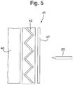
- Figure 5 shows a cross section of the armour appliqué arrangement 41 located upon the existing armour 40 on a vehicle (not shown).
- the armour 41 contains elements 42, with perforations (not shown), to defeat an incoming munition 50.
- Perforations of 8mm are typically used on perforated armour plates which are substantially flat (and are mounted such that they are presented at the normal to the incoming round).
- a 10mm hole may be used as the perforation diameter when presented on a chevron with a 90° angle of separation between the elements 42, and provide the same effect.
- the armour 41 further comprises an additional sheet of substantially flat armour material 47 located on the outer facing surface.
- the additional sheet of armour 47 also contains perforations.
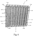
- the armour assembly 110 comprises a frame 112 that is rectangular in shape and is formed from a top wall 112a, a bottom wall 112b parallel to the top wall 112a and spaced therefrom, and two side walls 112c,d connecting the top and bottom walls 112a,b, where the side walls 112c,d are orientated perpendicularly relative to the top and bottom walls 112a,b.
- the frame is rigid and is made from steel or a similarly rigid material.
- the frame 112 has a plurality of armour plates 114 mounted thereto, where the armour plates 114 are perforated armour plates, each comprising a plurality of apertures 116 therethrough.
- the apertures 116 increase the number of edges present on the armour plates 114 and therefore increase the armour plates' 114 ability to prevent ballistic projectiles, such as bullets, from penetrating through the armour plates 114.
- One reason for this improved impenetrability is a consequence of the increased statistical likelihood that a ballistic projectile will at least partially contact one of the edges in the armour plates 114.
- an impacting ballistic projectile strikes an edge, it experiences an increased pressure when compared to the pressure it would experience when striking a flat surface of the same material. This increased pressure increases the likelihood that the ballistic projectile disintegrates on impact or is deflected, thereby reducing its energy, therefore reducing the depth of penetration through the armour plate 114.
- the frame 112 comprises fastening elements 118 that are used to attach the frame 112 (and therefore the entire armour assembly 110) to a vehicle so that the vehicle benefits from the protection provided by the armour assembly 110.
- fastening means other than fastening elements 118 are used to attach the armour assembly 110 to a vehicle.
- a vehicle may have several armour assemblies 110 attached to it to provide protection where desired.
- the armour assemblies 110 attached to the vehicle may be different sizes and shapes to one another to suit the shape of the vehicle.
- Figure 7 shows a detailed view of a single armour plate 114.
- the armour plate 114 is elongated along a longitudinal axis 115 of the armour plate 114, and comprises a body portion 114a, a bottom tab 114b extending from a bottom end of the body portion 114a in a direction parallel to the longitudinal axis 115, and a removal tab 114c extending from a top end (opposite the bottom end) of the body portion 114a in a direction parallel to the longitudinal axis 115.
- the bottom tab 114b has a width W 1 that is less than a width W 2 of the body portion 114a.
- the widths W 1 and W 2 are defined as being perpendicular to the longitudinal axis 115 of the armour plate 114 and in alternative examples, the bottom tab 114b may be smaller than the body portion 114a in any direction that is perpendicular to the longitudinal axis 115 and still perform its function, which will be described further below.
- the armour plate 114 comprises a narrow neck portion 114d between the removal tab 114c and the body portion 114a, however, in alternative examples, the removal tab 114c may simply be an extension of the body portion 114a having the same width as the body portion 114a with no neck portion 114d present. In other alternative example, the removal tab 114c may have a width greater than that (W 2 ) of the body portion 114a.
- the body portion 114a has a face 117a and a side 117b that is perpendicular to the face 117a.
- the apertures 116 in the armour plate 114 are in the face 117a of the body portion 114a and extend through the body portion 114a in a direction perpendicular to the face 117a.
- the frame 112 defines a frame plane between the walls 112a-d, and the armour plates 114 are arranged in the frame so that their longitudinal axes 115 are all aligned (i.e. are parallel) with one another and parallel to the frame plane.
- the top wall 112a has a plurality of top slots 113a that are sized so the body portion 114a of the armour plates 114 can pass therethrough.
- the bottom wall 112b has a plurality of bottom slots 113b that are sized to receive the bottom tabs 114b of armour plates 114, but not allow the body portion 114a to pass therethrough.
- the armour plates 114 are releasably mountable to the frame 112 where each armour plate 114 may be slotted through one of the top slots 113a until the bottom tab 114b passes through one of the bottom slots 113b. Once the bottom tab 114b passes through the bottom slot 113b, continued movement of the armour plate 114 relative to the bottom wall 112b is prevented by abutment between the body portion 114a and the bottom wall 112b, since each bottom slot 113b is sized to prevent the body portion 114a from passing therethrough.
- the armour plate 114 is in position for providing protection (i.e. a "protecting position").
- Figure 9 shows a view of the armour assembly 110 along direction A shown in Figure 6 .
- the bottom tabs 114b of the armour plates 114 can be seen protruding through the bottom slots 113b of the bottom wall 112b.
- the bottom slots may not pass all of the way through the bottom wall so that they are more recess-like but are still capable or receiving the bottom tabs 114b of the armour plates 114.
- the top and bottom walls 112a,b may comprise formations other than slots which may serve as guides to allow the armour plates 114 to be releasably mountable to the frame.
- the removal tabs 114c of the armour plates 114 protrude from the top slots 113a outside of the frame plane and provide a means for gripping the armour plates 114 and removing them from the frame 112 by withdrawal through the top and bottom slots 113a,b.
- the removal tabs 114c may be configured to be gripped by hand so that a person can remove each armour plate 114 by hand.
- the removal tabs 114c may be configured to be engaged by a tool that may assist or automatically remove the armour plates 114 from the frame 112.
- the top wall 112a may comprise two parts that are bolted or otherwise releasably attached together around the armour plates 114 in their protecting position.
- the two components of the top wall 112a may be opened to remove one or more armour plates 114 that may have become damaged and misshapen making removal through the slots 113a (or other formations) difficult or impossible.
- the slots or other formations may still be present to allow mounting and unmounting of the armour plates 114 by methods that do not require opening the two part top wall 112a (provided that the armour plates 114 are not misshapen so as to prevent such mounting and unmounting).
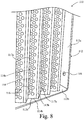
- the armour plates are orientated in the frame 112 so that the face 117a of each armour plate 114 is perpendicular to the face 117a of the adjacent armour plate(s) 114 forming a corrugated arrangement of armour plates 114.
- the side 117b of each armour plate 114 (except an end armour plate 114) is parallel and flush with the face 117a of an adjacent armour plate 114. This arrangement therefore eliminates any significant gaps between adjacent armour plates 114 that may compromise the armour assembly's 110 ability to resist ballistic projectiles.
- the edges of the apertures 116 of adjacent plates are orientated at different angles to one another which also improves the armour assembly's 110 ability to resist ballistic projectiles.
- the armour plates 114 may be arranged in the frame 112 in a different arrangement (e.g. at different relative angles) to the one shown in the Figures. The chosen arrangement may depend on the anticipated threat (i.e. expected type of incoming ballistic projectile) or weight and shape considerations in relation to the vehicle the assembly 110 is to be fitted to.
- the armour assembly 110 further comprises a locking mechanism that locks the armour plates 114 in their protecting positions within the frame.
- the locking mechanism may ensure that the armour plates 114 are not released nor move from their protecting positions inadvertently due to the motion of the vehicle or impact of ballistic projectiles.
- the frame 112 is mounted to a vehicle such as an armoured personnel carrier (APC).
- APC armoured personnel carrier
- the armour plates 114 arranged in their protecting positions in the frame 112 provide protection to the vehicle and its occupants.
- the armour plates 114 may be removed from the frame 114 by gripping the removal tabs 114c of the armour plates 114 and withdrawing them from the bottom slots 113b and through the top slots 113a out of the frame 112.
- the armour plates 114 may also be unmounted from the frame 112 by opening the two-part top wall 112a and removing the armour plates 114. With the armour plates 114 removed, the overall weight of the vehicle will be reduced and the speed, acceleration and manoeuvrability will not be hindered.
- the frame 112 remains attached to the vehicle once the armour plates 114 have been removed so that they may be easily and quickly mounted back on the frame 112 should protection be required again. The vehicle is therefore provided with means (i.e. the frame 112) to receive armour plates 114 whenever needed.
- An additional advantage of the present invention is that different types of perforated armour plates (e.g. thinner or thicker) may be easily fitted to the vehicle, provided that they fit with the frame 112 attached to the vehicle 112.
- Another advantage of the present invention is that individual armour plates 112 may be removed and replaced if damaged.
- the present invention is cost effective and requires less labour when compared to prior art arrangements where a whole armour plate (which is traditionally very large) requires unmounting from the vehicle and replacing in its entirety.
- the requirement of a large armour plate is negated in the present invention by the provision of the armour assembly 110 which comprises multiple smaller armour plates 114 thereby affording ease of use, cost effectiveness and improved operating of the vehicle, whilst providing a desired level of protection.
Landscapes
- Engineering & Computer Science (AREA)
- General Engineering & Computer Science (AREA)
- Aiming, Guidance, Guns With A Light Source, Armor, Camouflage, And Targets (AREA)
- Secondary Cells (AREA)
- Medicinal Preparation (AREA)
- Pharmaceuticals Containing Other Organic And Inorganic Compounds (AREA)
- Laminated Bodies (AREA)
Description
- This invention relates to an armour assembly and, more particularly, to an additional armour or applique style armour to provide additional protection to the primary armour system and to an armour assembly that is attachable to a vehicle.
- Vehicles, such as military vehicles, sometimes require armour to protect the vehicle and its occupants from harm when the vehicle is in a hostile environment, for example. The type of armour used on a vehicle will primarily depend on the type of anticipated threat, but consideration will also need to be given to the effect of the armour on the vehicle's performance (e.g. the effect on speed and/or manoeuvrability due to the weight of the armour).
- Appliqué armour is routinely used to provide a sacrificial or readily replaceable piece of armour, which defeats certain threats very effectively, but may not provide high levels of general protection from all forms of hazard threats likely to be encountered.
- It is known to use perforated armour plates to protect against kinetic energy projectiles such as ballistic firearm ammunition. Perforated armour comprises a sheet of armour, such as hardened steel, with a plurality of holes therethrough. In addition to being less heavy than solid armour (due to the presence of the holes), perforated armour can provide improved protection against ballistic projectiles. This improved protection at least partly arises from the increase in edged surfaces (i.e. around each hole) that are presented to an incoming ballistic projectile. With an increase in edged surfaces, an incoming ballistic projectile is statistically more likely to impact (or, at least, partially impact) on one of the edged surfaces and thereby experience a higher pressure than it would if it was to impact on a flat surface (such as unperforated armour). The increase of pressure increases the likelihood of the ballistic projectile disintegrating on impact or being deflected and thereby reducing its energy, and thus its ability to penetrate the armour.
- An example of an armour assembly comprising perforated armour is described in
EP-A-0209221 (The State of Israel Ministry of Defence Rafael - Armament Development Authority). The armour assembly ofEP-A-0209221 is specifically designed for armoured vehicles and comprises a perforated armour plate mounted to a conventional armour plate and spaced therefrom.WO2009/004596 discloses a removable appliqué armour system according to the preamble ofclaim 1. It is directed to armour plates positioned side-by- side such that they form the shape of a half-parabolic curve. - As mentioned above, whilst the addition of armour increases a vehicle's defences against ballistic projectiles, the added weight can impair the vehicle's ability to manoeuvre and travel at its optimal or preferred speed or acceleration rate, even when lighter perforated armour is used. This is a particular problem when considering vehicles that may be travelling in and out of known safe areas where no or less protection is required, or when travelling in areas where it is undesirable to compromise the vehicle's speed, acceleration or manoeuvrability. In these cases, the armour must be removed from the vehicle which is an onerous task that requires the personnel to be in possession of the appropriate tools.
- It is an object of the present invention to provide an armour assembly that overcomes the problems associated with the prior art.
- According to a first aspect of the invention there is provided a removable applique armour system (110), comprising, a rigid frame (112) formed from two side walls (112c,d), said frame arranged to be attached to a vehicle, wherein a plurality of armour plates (114) is arranged in the frame, wherein said armour plates are abutted along their longest dimension so as to provide a repeating arrangement, and arranged at an angle (α) between two abutting armour plates in the range of from 40° to 130°, wherein said plurality of armour plates provides the outermost facing armoured surface of the armour system, characterised in that the rigid frame is also formed by a top wall (112a) and a bottom wall (112b), said plurality of armour plates comprises a plurality of perforations (3), said armour plate arrangement provides a repeating upwards and downwards angled, chevron arrangement.
- The perforations when provided on an angled surface give rise to an effective perforation dimension which is approximately 30% less than if the perforation were presented on a substantially flat armour plate, i.e. when said plate is viewed normal to the plane, (or normal to an incoming munition fired directly at a target). This allows the use of larger dimensioned perforations, to achieve the required effect, with a concomitant reduction in mass of said armour. Alternatively, the same sized perforations as used on conventional flat armour may be used but with up to a 30% reduction in the effective dimension of said perforation.
- In an example not covered by the claims it is possible to have only one element provided at an angle in a louvre arrangement, which will provide protection from a projectile that is fired at an angle normal to the armour. However, a single louvre will provide only limited protection from any projectiles that are fired upwardly from ground level. An array of single louvres would require large numbers of elements, and each element would require a greater depth, to significantly reduce or eliminate any risk of upwardly fired projectiles. This would result in a system that is very bulky, i.e. very thick panel, and also possess a very high mass.
- The plurality of armour plates may be independently selected from any material, such as a metal, metal alloy, metalloid, ceramic, polymer or composite. Preferably the material is a known armour material, such as a high hardness steel or titanium. The plurality of armour plates, may have a surface which is substantially flat, curved or undulating, preferably the surface of the armour plates is substantially flat, to provide a chevron or V shaped cross section.
- The plurality of armour plates may be joined at their apex, and/or their troughs, by a reversible mechanical fixing, or they may be permanently fixed together by means of a weld or adhesive. The plurality of armour plates may be prepared from one piece of material.
- The angle between two armour plates is preferably in the range of from 40° to 130°, more preferably in the range of from 60° to 120°, yet more preferably of from 80° to 110°. The preferred angle for two armour plates is substantially 90°, to provide a chevron. If the angle is too acute, i.e. less than 40° the aspect of the chevron is very steep and there are too few perforations that are being presented to cause disruption of incoming projectiles. Further if the angle is too obtuse, i.e. greater than 130°, then the chevron is fairly flat such that the effective diameter of the perforation tends towards that of a flat perforation armour panel.
- The plurality of armour plates are arranged such that the surface face of the plurality of armour plates is repeatedly angled upwards and downwards, and their longest axis is substantially parallel with the ground plane that the wheel base of the vehicle is located upon, as this provides a consistent level of protection in azimuth. The performance of the armour system may be reduced if the at least two armour plates longest axis was mounted substantially perpendicular to said ground plane. It is more likely that the vehicle will attacked by a projectile incoming from a range of azimuth angles, but will predominantly be shot from within a few degrees off horizontal for elevation.
- The perforation may have a shortest dimension which is less than the diameter of the primary threat projectile. Where the perforation is circular the diameter of the perforation is less than the diameter of the primary threat projectile. The perforation may be provided as a partial perforation, such as, for example a blind hole that does not extend all the way through the at least two armour plates, or more preferably the perforation is a full perforation, such that the hole/perforation extends all the way through the at least two armour plates.
- The perforation may have any shape, preferably a polygon, more preferably the shape is selected from circular, square, elliptical, and slots; other configurations to provide identification or insignia may be selected. Preferably the perforation is circular. In a further arrangement the perforation may have a bevelled edge, so as to provide different cross section size of perforation on a front face and rear face of each said at least two armour plates.
- The distance between perforations is selected to provide strength in the armour system, but also to maximise the number of perforations per unit area. Preferably the perforations have a longest dimension, and the distance between each perforation may be at least one half of the length of said longest dimension. Therefore in an armour system with circular perforations, the distance between each perforation is substantially half of the diameter of the circular perforation.
- Where the armour is fitted to a vehicle, and said vehicle passes through terrain comprising mud, stones, etc, the perforations may become partially or completely blocked with unwanted debris. This adds extra mass, and may cause accelerated corrosion, and further may reduce the effectiveness of the perforations. In a preferred arrangement the perforations may be filled with a potting compound, such as, for example a resin, polymer, or rubber. The potting compound is designed to keep the perforation free from debris, and potentially mask the presence of perforations.
- An alternative means of masking the presence of the perforations is to provide a sheet of substantially flat armour material which may be located on the outer facing surface, which optionally contains perforations.
- Louvre arrangements are often used on vehicles in theatre to provide thermal ID panels, by reflecting IR radiation from space, so as to provide cold patches on a thermally hot vehicle. In a preferred arrangement at least one of the at least two armour plates may be provided with an IR reflective coating. The armour plates which face skywards, namely at 45° away from the normal towards the sky require IR coating, both of the at least two armour plates may be coated if the device can be fixed in any orientation.
- In an example, there is provided a first set of at least two armour plates, and second set of at least two armour plates such that said second set is mounted behind the first, to provide a tandem arrangement, wherein said armour plates are arranged at an angle (α), characterised in that said at least two armour plates comprise a plurality of
perforations 3 and form a chevron shaped surface. Alternatively, the rear set of at least two armour plates may be orientated at an angle, such as, for example, 90° to the first set of at least two armour plates. - The armour system may sustain damage during use, preferably one or more armour plates are independently removable and replaceable with new at least two armour plates.
- The appliqué system is designed as a modular arrangement such that it may be readily retrofitted to an existing armour arrangement, without an extensive refitting program. In a further arrangement the appliqué system may be readily removable such that a damaged appliqué system can be replaced without removing the vehicle from active service. The replacement of an element or the at least two armour plates may then be undertaken at a separate location to the vehicle.
- The at least two armour plates are arranged, such that the axis of their longest dimension is substantially parallel with respect to the ground plane, upon which the vehicle wheel base is located thereon.
- The armour appliqué may be entirely potted in with a potting compound, as hereinbefore defined, to provide the appearance of a non perforated structure.
- In an example not covered by the claims the at least two armour plates may be prepared from a single piece of armour material which is formed to provide at least two surfaces, which provide the same effect as the at least two armour plates as hereinbefore defined. In a further example there is provided an armour system, comprising at least one element, wherein each element comprises at least two surfaces arranged at an angle (α), characterised in that said element comprises a plurality of perforations and form a chevron shaped surface.. Furthermore, the repeating units of armour plates may be prepared from one piece of material.
- The armour assembly of the present invention provides protection against ballistic projectiles such as bullets and other firearm ammunition, but allows the armour plates to be easily removed when not required so that the vehicle's performance is not unduly compromised. Preferably, the frame is attached to the vehicle and remains attached, whereas the armour plates may be mounted and unmounted from the frame when desired. The frame of the armour assembly is rigid so that the whole assembly is strong and is effective at protecting against incoming ballistic projectiles.
- An additional advantage of the armour assembly of the present invention is that if one or more of the armour plates gets damaged, only the damaged armour plates need to be replaced, thereby reducing costs and the burden of replacing damaged armour. This is in contrast to prior art arrangements where the entire plate (which is often large and may cover an entire side of a vehicle) needs to be replaced if a portion of it gets damaged. This is a significant feature as individual damaged armour plates may be replaced quickly without the requirement of specialist toots in a potentially hostile environment where it would be highly undesirable to be travelling in a vehicle with damaged and compromised armour.
- In an example, the frame defines a frame plane, where each of the plurality of armour plates has a longitudinal axis and is releasably mountable to the frame so that each longitudinal axis may be orientated substantially parallel to the frame plane. This example allows a regular array of armour plates to be arranged in the frame which offers a particularly effective armour arrangement against ballistic projectiles, but also allows for simple, quick and easy mounting and unmounting of the armour plates in the frame. In an example, the plurality of armour plates may be orientated so that each armour plate is adjacent to at least one other armour plate. In this example, protection provided by the armour assembly is maximized.
- In an example, each of the plurality of armour plates has a face, and the plurality of armour plates may be orientated so that the face of each armour plate is perpendicular to the face of the at least one other armour plate. In this example the armour plates are orientated in a preferential arrangement that is particularly effective at providing protection from ballistic projectiles, due to the orientation of the edges of the holes in the armour plates.
- The frame has four walls including a top wall, a bottom wall and two side walls extending between the top and bottom walls; and wherein the top wall comprises top guides and the bottom wall comprises bottom guides, and the top and bottom guides are arranged so that each of the plurality of armour plates is releasably mountable in both a top guide and a bottom guide. In this example, the frame has a particularly strong structure whereby the plurality of armour plates are mounted thereon and the risk of disruption of the arrangement of armour plates due to compromise of the frame structure is minimized. In a further example, the top guides are top slots in the top wall and the bottom guides are bottom slots in the bottom wall, wherein each of the slots is arranged to receive one of the plurality of armour plates. In this example, the slots provide a means of guiding the armour plates into and out of frame when mounting and unmounting and provide a secure means of preventing unwanted movement of the armour plates relative to the frame when in position in the frame.
- Further preferably, each of the plurality of armour plates comprises a body portion and a bottom tab extending from the body portion in a direction parallel to the longitudinal axis, where the bottom tab is smaller than the body portion in at least one direction perpendicular to the longitudinal axis; and wherein the bottom tab is receivable in one of the bottom slots of the bottom wall, and where the bottom slot is sized so as to prevent passage of the body portion therethrough. This example provides an improved means of securely retaining the armour plates in the frame and limits further movement along a direction parallel to the longitudinal axes of the plates once a suitable position has been reached.
- Alternatively or additionally, each of the plurality of armour plates comprises a removal tab that facilitates the removal of the armour plate from the frame. In one preferable embodiment the removal tab is configured to be gripped by a hand thereby facilitating manual removal. In an alternative example, the removal tab is configured to be engaged by a removal tool thereby providing a means for removing the armour plates from the frame using a tool which may be automatic and non-manual. In one example, the removal tab extends from the body portion of each armour plate in a direction parallel to its longitudinal axis from an opposite end of the body portion to the bottom tab.
- In examples, the armour assembly further comprises a locking mechanism that releasably locks the plurality of armour plates in a configuration when mounted to the frame. In this example, the locking mechanism ensures that the armour plates are securely mounted to the frame and are unable to be unmounted therefrom until the locking mechanism is unlocked.
- Each of the plurality of armour plates preferably comprises an armour steel plate.
- In accordance with a further aspect of the present invention there is provided a vehicle comprising the armour assembly of the present invention. The vehicle will benefit from having the ability to have the armour plates quickly and easily removed when they are not needed or replaced with lighter or heavier armour plates as desired, and the ability to have individual armour plates replaced if they become damaged, for example. Therefore the vehicle is afforded a flexibility with regards to its armour protection which can allow the vehicle to easily switch between different levels of protection as it travels through environments of varying hostility.
- Examples of the invention are further described hereinafter with reference to the accompanying drawings, in which:
-
Figure 1 shows an armour system within a housing; -
Figure 2 shows a cross section of the at least two armour plates and the separation angle (α); -
Figure 3 shows a cross section of the at least two armour plates with different perforation arrangements; -
Figure 4 shows a vehicle comprising an armour system as shown inFigure 1 ; -
Figure 5 shows a cross section of vehicle's armour in conjunction with the appliqué armour system and additional cover plate; -
Figure 6 is a perspective view of an armour assembly according to the present invention; -
Figure 7 is a detailed perspective view of an embodiment of an amour plate for use with the armour assembly ofFigure 6 ; -
Figure 8 is a detailed perspective view of a part of the armour assembly ofFigure 6 ; and -
Figure 9 shows a partial view of the armour assembly ofFigure 6 as viewed along direction A. - Turning to
Figure 1 , there is provided anarmour system 1, which is optionally contained in a housing 9 (or frame) to form an appliqué armour system, or thearmour 1 may be directly applied to an existing armour structure. Thehousing 9 contains a plurality of at least twoelements 2, whereinelements apex 7 andtroughs 8, to form a continuous armour system. Theelements 2, comprise a plurality ofperforations 3. The housing may be fixed bylugs 10 to a vehicle. Theelements elements elements 2, their longest dimension axis is substantially parallel with the ground plane on which the vehicles wheel base is located (seeFigure 4 ). -
Figure 2 shows a cross section ofelements perforation 13 located in the elements. -
Figure 3 shows a cross section as inFigure 2 , whereinperforation 23 is a substantially circular cross sectioned perforation which extends all the way through theelement 22a. A further example of a perforation is abevelled edge perforation 26, wherein the diameter of the perforation on the outer surface ofelement 22a is larger than the diameter of the perforation on the inner surface ofelement 22a. As described above, the vehicles may during manoeuvres pick up debris, which may block theperforations 23, therefore it may be advantageous to provide aplug 24, provided by a potting compound to provide a temporary fill of theperforation 23. A yet further example of perforation may be a partial orblind perforation 25, wherein the perforation does not extend fully through theelement 22b. -
Figure 4 shows anarmoured vehicle 30, comprising anarmour system 31, in the form of anappliqué system 31. The appliqué system, may be any dimension, such that there may be a plurality of appliqué systems mounted on the side of the vehicle. The vehicle has aground plane 39 that the wheel base is located upon. Theelements ground plane 39 of thevehicle 30, during operation on substantially flat terrain. It may be desirable for an IR reflective coating to be applied toelements 32a, which nominally face skywards, such as to provide a thermal cold patch for identification purposes. -
Figure 5 shows a cross section of thearmour appliqué arrangement 41 located upon the existingarmour 40 on a vehicle (not shown). Thearmour 41, containselements 42, with perforations (not shown), to defeat anincoming munition 50. Perforations of 8mm are typically used on perforated armour plates which are substantially flat (and are mounted such that they are presented at the normal to the incoming round). In the present invention a 10mm hole may be used as the perforation diameter when presented on a chevron with a 90° angle of separation between theelements 42, and provide the same effect. Clearly the use of a 10mm diameter hole provides less machining costs, and a reduced mass system, whilst providing the same level of protection as afforded by a conventional flat armour plate with 8mm perforations. Alternatively an 8mm hole may be used, such that the perforation is capable of disrupting smaller diameter rounds. In the preferable embodiment shown inFigure 5 , thearmour 41 further comprises an additional sheet of substantiallyflat armour material 47 located on the outer facing surface. In some preferable embodiments, the additional sheet ofarmour 47 also contains perforations. - An
armour assembly 110 according to the present invention is shown inFigure 6 . Thearmour assembly 110 comprises aframe 112 that is rectangular in shape and is formed from atop wall 112a, abottom wall 112b parallel to thetop wall 112a and spaced therefrom, and twoside walls 112c,d connecting the top andbottom walls 112a,b, where theside walls 112c,d are orientated perpendicularly relative to the top andbottom walls 112a,b. The frame is rigid and is made from steel or a similarly rigid material. - The
frame 112 has a plurality ofarmour plates 114 mounted thereto, where thearmour plates 114 are perforated armour plates, each comprising a plurality ofapertures 116 therethrough. Theapertures 116 increase the number of edges present on thearmour plates 114 and therefore increase the armour plates' 114 ability to prevent ballistic projectiles, such as bullets, from penetrating through thearmour plates 114. One reason for this improved impenetrability is a consequence of the increased statistical likelihood that a ballistic projectile will at least partially contact one of the edges in thearmour plates 114. When an impacting ballistic projectile strikes an edge, it experiences an increased pressure when compared to the pressure it would experience when striking a flat surface of the same material. This increased pressure increases the likelihood that the ballistic projectile disintegrates on impact or is deflected, thereby reducing its energy, therefore reducing the depth of penetration through thearmour plate 114. - The
frame 112 comprisesfastening elements 118 that are used to attach the frame 112 (and therefore the entire armour assembly 110) to a vehicle so that the vehicle benefits from the protection provided by thearmour assembly 110. In alternative examples, fastening means other than fasteningelements 118 are used to attach thearmour assembly 110 to a vehicle. A vehicle may haveseveral armour assemblies 110 attached to it to provide protection where desired. Thearmour assemblies 110 attached to the vehicle may be different sizes and shapes to one another to suit the shape of the vehicle. -
Figure 7 shows a detailed view of asingle armour plate 114. Thearmour plate 114 is elongated along alongitudinal axis 115 of thearmour plate 114, and comprises abody portion 114a, abottom tab 114b extending from a bottom end of thebody portion 114a in a direction parallel to thelongitudinal axis 115, and aremoval tab 114c extending from a top end (opposite the bottom end) of thebody portion 114a in a direction parallel to thelongitudinal axis 115. Thebottom tab 114b has a width W1 that is less than a width W2 of thebody portion 114a. The widths W1 and W2 are defined as being perpendicular to thelongitudinal axis 115 of thearmour plate 114 and in alternative examples, thebottom tab 114b may be smaller than thebody portion 114a in any direction that is perpendicular to thelongitudinal axis 115 and still perform its function, which will be described further below. - In
Figures 6 to 9 , thearmour plate 114 comprises anarrow neck portion 114d between theremoval tab 114c and thebody portion 114a, however, in alternative examples, theremoval tab 114c may simply be an extension of thebody portion 114a having the same width as thebody portion 114a with noneck portion 114d present. In other alternative example, theremoval tab 114c may have a width greater than that (W2) of thebody portion 114a. - The
body portion 114a has aface 117a and aside 117b that is perpendicular to theface 117a. Theapertures 116 in thearmour plate 114 are in theface 117a of thebody portion 114a and extend through thebody portion 114a in a direction perpendicular to theface 117a. - Returning to the invention shown in
Figure 6 , theframe 112 defines a frame plane between thewalls 112a-d, and thearmour plates 114 are arranged in the frame so that theirlongitudinal axes 115 are all aligned (i.e. are parallel) with one another and parallel to the frame plane. Thetop wall 112a has a plurality oftop slots 113a that are sized so thebody portion 114a of thearmour plates 114 can pass therethrough. Thebottom wall 112b has a plurality ofbottom slots 113b that are sized to receive thebottom tabs 114b ofarmour plates 114, but not allow thebody portion 114a to pass therethrough. - The
armour plates 114 are releasably mountable to theframe 112 where eacharmour plate 114 may be slotted through one of thetop slots 113a until thebottom tab 114b passes through one of thebottom slots 113b. Once thebottom tab 114b passes through thebottom slot 113b, continued movement of thearmour plate 114 relative to thebottom wall 112b is prevented by abutment between thebody portion 114a and thebottom wall 112b, since eachbottom slot 113b is sized to prevent thebody portion 114a from passing therethrough. Therefore, once thearmour plate 114 has been slotted through the top andbottom slots 113a,b until no further movement is permitted due to abutment between thebody portion 114a and thebottom wall 112b, thearmour plate 114 is in position for providing protection (i.e. a "protecting position"). -
Figure 9 shows a view of thearmour assembly 110 along direction A shown inFigure 6 . InFigure 9 , thebottom tabs 114b of thearmour plates 114 can be seen protruding through thebottom slots 113b of thebottom wall 112b. In alternative examples, the bottom slots may not pass all of the way through the bottom wall so that they are more recess-like but are still capable or receiving thebottom tabs 114b of thearmour plates 114. In alternative examples, the top andbottom walls 112a,b may comprise formations other than slots which may serve as guides to allow thearmour plates 114 to be releasably mountable to the frame. - In the protecting position, the
removal tabs 114c of thearmour plates 114 protrude from thetop slots 113a outside of the frame plane and provide a means for gripping thearmour plates 114 and removing them from theframe 112 by withdrawal through the top andbottom slots 113a,b. Theremoval tabs 114c may be configured to be gripped by hand so that a person can remove eacharmour plate 114 by hand. Alternatively, theremoval tabs 114c may be configured to be engaged by a tool that may assist or automatically remove thearmour plates 114 from theframe 112. - In an alternative example, the
top wall 112a may comprise two parts that are bolted or otherwise releasably attached together around thearmour plates 114 in their protecting position. Thus, the two components of thetop wall 112a may be opened to remove one ormore armour plates 114 that may have become damaged and misshapen making removal through theslots 113a (or other formations) difficult or impossible. In this embodiment, the slots or other formations may still be present to allow mounting and unmounting of thearmour plates 114 by methods that do not require opening the twopart top wall 112a (provided that thearmour plates 114 are not misshapen so as to prevent such mounting and unmounting). - In the example shown in the Figures (see
Figure 8 , in particular), the armour plates are orientated in theframe 112 so that theface 117a of eacharmour plate 114 is perpendicular to theface 117a of the adjacent armour plate(s) 114 forming a corrugated arrangement ofarmour plates 114. In this corrugated arrangement, theside 117b of each armour plate 114 (except an end armour plate 114) is parallel and flush with theface 117a of anadjacent armour plate 114. This arrangement therefore eliminates any significant gaps betweenadjacent armour plates 114 that may compromise the armour assembly's 110 ability to resist ballistic projectiles. Also, in the corrugated arrangement the edges of theapertures 116 of adjacent plates are orientated at different angles to one another which also improves the armour assembly's 110 ability to resist ballistic projectiles. In alternative examples, thearmour plates 114 may be arranged in theframe 112 in a different arrangement (e.g. at different relative angles) to the one shown in the Figures. The chosen arrangement may depend on the anticipated threat (i.e. expected type of incoming ballistic projectile) or weight and shape considerations in relation to the vehicle theassembly 110 is to be fitted to. - In an alternative example not shown in the Figures, the
armour assembly 110 further comprises a locking mechanism that locks thearmour plates 114 in their protecting positions within the frame. The locking mechanism may ensure that thearmour plates 114 are not released nor move from their protecting positions inadvertently due to the motion of the vehicle or impact of ballistic projectiles. - In a preferable use of the
armour assembly 110, theframe 112 is mounted to a vehicle such as an armoured personnel carrier (APC). Thearmour plates 114 arranged in their protecting positions in theframe 112 provide protection to the vehicle and its occupants. When the vehicle is travelling in known safe areas, thearmour plates 114 may be removed from theframe 114 by gripping theremoval tabs 114c of thearmour plates 114 and withdrawing them from thebottom slots 113b and through thetop slots 113a out of theframe 112. In the above-described example where thetop wall 112a comprises two parts releasably attached to one another, thearmour plates 114 may also be unmounted from theframe 112 by opening the two-part top wall 112a and removing thearmour plates 114. With thearmour plates 114 removed, the overall weight of the vehicle will be reduced and the speed, acceleration and manoeuvrability will not be hindered. In preferable examples theframe 112 remains attached to the vehicle once thearmour plates 114 have been removed so that they may be easily and quickly mounted back on theframe 112 should protection be required again. The vehicle is therefore provided with means (i.e. the frame 112) to receivearmour plates 114 whenever needed. An additional advantage of the present invention is that different types of perforated armour plates (e.g. thinner or thicker) may be easily fitted to the vehicle, provided that they fit with theframe 112 attached to thevehicle 112. Another advantage of the present invention is thatindividual armour plates 112 may be removed and replaced if damaged. Thus, the present invention is cost effective and requires less labour when compared to prior art arrangements where a whole armour plate (which is traditionally very large) requires unmounting from the vehicle and replacing in its entirety. The requirement of a large armour plate is negated in the present invention by the provision of thearmour assembly 110 which comprises multiplesmaller armour plates 114 thereby affording ease of use, cost effectiveness and improved operating of the vehicle, whilst providing a desired level of protection. - The skilled reader will appreciate that any non-mutually exclusive features described above in relation to
Figures 1 to 5 may be combined with or interchanged with the features described above in relation toFigures 6 to 9 . - Throughout the description and claims of this specification, the words "comprise" and "contain" and variations of them mean "including but not limited to", and they are not intended to (and do not) exclude other moieties, additives, components, integers or steps. Throughout the description and claims of this specification, the singular encompasses the plural unless the context otherwise requires. In particular, where the indefinite article is used, the specification is to be understood as contemplating plurality as well as singularity, unless the context requires otherwise.
- Features, integers, characteristics, compounds, chemical moieties or groups described in conjunction with a particular aspect, embodiment or example of the invention are to be understood to be applicable to any other aspect, embodiment or example described herein unless incompatible therewith. All of the features disclosed in this specification (including any accompanying claims, abstract and drawings), and/or all of the steps of any method or process so disclosed, may be combined in any combination, except combinations where at least some of such features and/or steps are mutually exclusive. The invention is not restricted to the details of any foregoing examples, but is defined by the appended claims.
Claims (8)
- A removable applique armour system (110) comprising, a rigid frame (112) formed from two side walls (112c,d), said frame arranged to be attached to a vehicle,
wherein a plurality of armour plates (114) is arranged in the frame,
wherein said armour plates are abutted along their longest dimension so as to provide a repeating arrangement, and arranged at an angle (α) between two abutting armour plates in the range of from 40° to 130°,
wherein said plurality of armour plates provides the outermost facing armoured surface of the armour system, characterised in that
the rigid frame is also formed by a top wall (112a) and a bottom wall (112b), said plurality of armour plates comprises a plurality of perforations (3), said armour plate arrangement provides a repeating upwards and downwards angled, chevron arrangement. - An armour system according to claim 1, wherein the perforation 3 has a shortest dimension which is less than the diameter of the primary threat projectile (50).
- An armour system according to any one of the preceding claims, wherein the perforation has a cross sectioned shape selected from circular, square, elliptical, and a slot.
- An armour system according to any one of the preceding claims, wherein the perforation has a bevelled edge, so as to provide different cross section size on a front face and rear face of said plurality of armour plates.
- An armour system according to any one of the preceding claims, wherein the perforations are filled with a potting compound (24).
- An armour system according to any one of claims 1 to 5, wherein there is provided an IR reflective coating on at least one of the said plurality of armour plates.
- An armour system according to any one of the preceding claims wherein the plurality of armour plates (114) are releasably mountable to the frame and removable therefrom.
- A vehicle, vessel or craft comprising an armour applique system according to any one of the preceding claims.
Applications Claiming Priority (2)
| Application Number | Priority Date | Filing Date | Title |
|---|---|---|---|
| GB1014569.6A GB2483267B (en) | 2010-09-02 | 2010-09-02 | Armour assembly |
| PCT/GB2011/051650 WO2012028888A1 (en) | 2010-09-02 | 2011-09-02 | Armour assembly |
Publications (2)
| Publication Number | Publication Date |
|---|---|
| EP2612102A1 EP2612102A1 (en) | 2013-07-10 |
| EP2612102B1 true EP2612102B1 (en) | 2017-08-02 |
Family
ID=43013554
Family Applications (1)
| Application Number | Title | Priority Date | Filing Date |
|---|---|---|---|
| EP11754472.6A Active EP2612102B1 (en) | 2010-09-02 | 2011-09-02 | Armour assembly |
Country Status (5)
| Country | Link |
|---|---|
| US (1) | US9470481B2 (en) |
| EP (1) | EP2612102B1 (en) |
| AU (1) | AU2011298116B2 (en) |
| GB (2) | GB2483267B (en) |
| WO (1) | WO2012028888A1 (en) |
Families Citing this family (13)
| Publication number | Priority date | Publication date | Assignee | Title |
|---|---|---|---|---|
| DK2718663T3 (en) | 2011-06-08 | 2018-10-29 | American Technical Coatings Inc | ENHANCED BALLIST PROTECTION SYSTEM |
| DE102013008941A1 (en) * | 2013-05-25 | 2014-11-27 | Diehl Bgt Defence Gmbh & Co. Kg | Arrangement for protecting an object, in particular a motor vehicle, against approaching projectiles |
| WO2015179013A2 (en) * | 2014-03-18 | 2015-11-26 | American Technical Coatings, Inc. | Lightweight enhanced ballistic armor system |
| US9952021B2 (en) * | 2015-07-29 | 2018-04-24 | Frontline Ballistic Barriers, LLC | Anti-ballistic barrier for high value facilities protection such as electrical grid equipment |
| US10053887B2 (en) * | 2015-08-31 | 2018-08-21 | Battelle Energy Alliance, Llc. | Protective barriers and related methods |
| US9459079B1 (en) * | 2015-09-30 | 2016-10-04 | The United States Of America As Represented By The Secretary Of The Navy | Lightweight armor with slide region for slidably redirecting projectiles |
| CA2907287A1 (en) * | 2015-10-09 | 2017-04-09 | Chemposite Inc. | Ballistic panel |
| US10012479B2 (en) * | 2016-02-22 | 2018-07-03 | Michael Boviall | Ballistic barrier |
| DE102017101478A1 (en) * | 2017-01-26 | 2018-07-26 | Rheinmetall Waffe Munition Gmbh | Device for venting or ventilating a room |
| US11243051B2 (en) * | 2019-07-08 | 2022-02-08 | Phillip D. Roux | Ballistic protection system and method therefor |
| TR202003526A1 (en) * | 2020-03-06 | 2021-09-21 | Secant Teknoloji Gelistirme Sanayi Ve Ticaret Anonim Sirketi | ADDITIONAL ARMOR SYSTEM FOR ARMORED VEHICLES |
| IL299386A (en) * | 2022-12-22 | 2024-07-01 | Cohen Michael | Armor protection against large explosive devices |
| EP4571236A1 (en) * | 2023-12-15 | 2025-06-18 | Benteler Automobiltechnik GmbH | Zigzag shaped protective element and method for the production thereof |
Citations (2)
| Publication number | Priority date | Publication date | Assignee | Title |
|---|---|---|---|---|
| EP1517110A1 (en) * | 2003-09-16 | 2005-03-23 | GEKE Technologie GmbH | Combined protection system |
| WO2009004596A2 (en) * | 2007-07-05 | 2009-01-08 | Bae Systems Land Systems South Africa (Pty) Limited | Armour arrangement |
Family Cites Families (33)
| Publication number | Priority date | Publication date | Assignee | Title |
|---|---|---|---|---|
| GB126671A (en) * | 1917-02-02 | 1919-05-22 | William Ashbee Tritton | Improvements in and relating to Armour Plating. |
| US1438109A (en) * | 1921-07-12 | 1922-12-05 | Thomas H Schrider | Shield |
| US2372636A (en) * | 1942-01-19 | 1945-03-27 | Mindt Karl | Metal bulletproof window |
| US2392215A (en) * | 1944-11-17 | 1946-01-01 | Barber Colman Co | Bulletproof grid |
| US5149910A (en) * | 1966-03-08 | 1992-09-22 | Fmc Corporation | Polyphase armor with spoiler plate |
| US3765299A (en) * | 1968-09-06 | 1973-10-16 | Us Army | Universal applique armor |
| BE759412A (en) * | 1969-12-18 | 1971-05-25 | Hoesch Ag | PROTECTIVE SHIELDING |
| DE2051970C1 (en) | 1970-10-22 | 1978-10-19 | Blohm + Voss Ag, 2000 Hamburg | Method for producing a neutron shield |
| US4325309A (en) * | 1974-08-06 | 1982-04-20 | The United States Of America As Represented By The Secretary Of The Army | Blast suppressive shielding |
| US4005662A (en) * | 1975-03-21 | 1977-02-01 | Kohn Robert A | Armor window |
| EP0209221A1 (en) * | 1985-06-20 | 1987-01-21 | The State Of Israel Ministry Of Defence Rafael Armament Development Authority | An armour assembly for armoured vehicles |
| IL75980A0 (en) | 1985-07-31 | 1985-12-31 | Israel State | Earth moving vehicle with armoured cab |
| US4716810A (en) * | 1986-02-24 | 1988-01-05 | Detroit Punch & Retainer Corporation | Self-contained armor assembly |
| US4727789A (en) * | 1986-06-24 | 1988-03-01 | T & E International, Inc. | Vented suppressive shielding |
| US5014593A (en) * | 1988-03-01 | 1991-05-14 | General Dynamics Land Systems, Inc. | Perforated plate armor |
| FR2652821B1 (en) * | 1989-10-09 | 1994-02-18 | Creusot Loire Industrie | HIGH-HARDNESS STEEL FOR SHIELDING AND PROCESS FOR PREPARING SUCH STEEL. |
| US5007326A (en) * | 1990-01-16 | 1991-04-16 | The United States Of America As Represented By The Secretary Of The Army | Cast single plate P900 armor |
| DE4035890C2 (en) * | 1990-11-12 | 1996-09-19 | Koch Marion | Wearable protective armor shaped to fit the body |
| EP0489183A1 (en) * | 1990-12-03 | 1992-06-10 | Luwa Ltd. | Passive explosion protection organ |
| US5370034A (en) * | 1993-07-02 | 1994-12-06 | Fmc Corporation | Reactive armor system with improved flyplates |
| DE19634227C1 (en) | 1996-08-23 | 1998-01-08 | Krupp Ag Hoesch Krupp | Connection of a frame of a grating for special vehicles, such as armored vehicles, to the profile strips of the grating |
| DK0912875T3 (en) * | 1997-02-12 | 2001-05-07 | Schweizerische Eidgenossenschaft Eidgenoessisches Militaer Departement Gruppe Ruestung | camouflage Structure |
| US6405630B1 (en) * | 2000-11-03 | 2002-06-18 | The United States Of America As Reresented By The Secretary Of The Army | Foraminous ballistic grill |
| FR2827375B1 (en) * | 2001-07-12 | 2004-01-16 | France Etat | MULTI-LAYER COMPOSITE SHIELDING |
| US7513186B2 (en) * | 2004-03-11 | 2009-04-07 | Plasan-Kibbutz Sasa | Ballistic armor |
| US7191694B1 (en) * | 2004-05-07 | 2007-03-20 | United States Of America As Represented By The Secretary Of The Army | Edge reinforced brittle armor system |
| US7473167B2 (en) * | 2006-07-28 | 2009-01-06 | Met California Group Llc | Security module for use with ventilation grating |
| WO2009048942A2 (en) | 2007-10-08 | 2009-04-16 | Bae Systems Land & Armaments L.P. | Armored window system |
| US20110168000A1 (en) * | 2008-03-03 | 2011-07-14 | Langner F Richard | Ballistic wall panel device and system and method therefor |
| AU2010201270A1 (en) * | 2009-04-07 | 2010-10-21 | Plasan Sasa Ltd. | Safety apparatus for providing protection against an explosion and vehicle comprising same |
| US8424443B2 (en) * | 2011-01-31 | 2013-04-23 | The United States Of America As Represented By The Secretary Of The Army | Vented armor V structure |
| US20130180393A1 (en) * | 2011-02-01 | 2013-07-18 | Sgl Carbon Se | Defensive, ceramic based, applique armor, device for providing anti-projectile armoring protection and process for producing ceramic based projectile armor with hollow geometry |
| DK2718663T3 (en) * | 2011-06-08 | 2018-10-29 | American Technical Coatings Inc | ENHANCED BALLIST PROTECTION SYSTEM |
-
2010
- 2010-09-02 GB GB1014569.6A patent/GB2483267B/en not_active Expired - Fee Related
-
2011
- 2011-09-02 GB GB1303791.6A patent/GB2501971A/en not_active Withdrawn
- 2011-09-02 US US13/820,281 patent/US9470481B2/en active Active
- 2011-09-02 AU AU2011298116A patent/AU2011298116B2/en active Active
- 2011-09-02 EP EP11754472.6A patent/EP2612102B1/en active Active
- 2011-09-02 WO PCT/GB2011/051650 patent/WO2012028888A1/en not_active Ceased
Patent Citations (2)
| Publication number | Priority date | Publication date | Assignee | Title |
|---|---|---|---|---|
| EP1517110A1 (en) * | 2003-09-16 | 2005-03-23 | GEKE Technologie GmbH | Combined protection system |
| WO2009004596A2 (en) * | 2007-07-05 | 2009-01-08 | Bae Systems Land Systems South Africa (Pty) Limited | Armour arrangement |
Also Published As
| Publication number | Publication date |
|---|---|
| GB2501971A (en) | 2013-11-13 |
| AU2011298116B2 (en) | 2016-01-28 |
| WO2012028888A1 (en) | 2012-03-08 |
| GB201303791D0 (en) | 2013-04-17 |
| GB2483267A (en) | 2012-03-07 |
| US20130160640A1 (en) | 2013-06-27 |
| US9470481B2 (en) | 2016-10-18 |
| GB2483267B (en) | 2014-10-15 |
| AU2011298116A1 (en) | 2013-03-21 |
| GB201014569D0 (en) | 2010-10-13 |
| EP2612102A1 (en) | 2013-07-10 |
Similar Documents
| Publication | Publication Date | Title |
|---|---|---|
| AU2011298116B2 (en) | Armour assembly | |
| EP2697596B1 (en) | Net patching devices | |
| US11015903B2 (en) | Enhanced ballistic protective system | |
| US20060213360A1 (en) | Perforated armor plates | |
| EP1331466B1 (en) | Armor module | |
| US20070186762A1 (en) | Armored vehicle with blast deflecting hull | |
| EP2040024B1 (en) | Reactive armor module | |
| CA2747532C (en) | Object protection from hollow charges and method for the production thereof | |
| EP2780657B1 (en) | Vehicle and structure shield with improved hard points | |
| WO2012067635A2 (en) | Vehicle and structure shield hard point | |
| IL160843A (en) | Ballistic armor with particularly a layer of hard bodies | |
| EP0209221A1 (en) | An armour assembly for armoured vehicles | |
| US20220107161A1 (en) | Ballistic protection system and method therefor | |
| US6718861B1 (en) | Momentum trap ballistic armor system | |
| US8166863B2 (en) | Magnetic damping field armor system | |
| US20140373707A1 (en) | Arrangement for the protection of an object, especially of a motor vehicle, against approaching projectiles | |
| EP2715271B1 (en) | A lightweight bar armor | |
| US11402177B2 (en) | Composite grid/slat-armor | |
| EP3650802B1 (en) | A protective front screen against shape charged warheads | |
| US12429310B2 (en) | Reactive protective armor | |
| WO2018065791A1 (en) | Improved vehicle armour | |
| US12455144B2 (en) | Ballistic protection system and method therefor | |
| GB2494643A (en) | Modular armour assembly unit | |
| EP1750080A1 (en) | Ceramic armor against kinetic threats | |
| IL266492A (en) | Composite grid/slat-armor |
Legal Events
| Date | Code | Title | Description |
|---|---|---|---|
| PUAI | Public reference made under article 153(3) epc to a published international application that has entered the european phase |
Free format text: ORIGINAL CODE: 0009012 |
|
| 17P | Request for examination filed |
Effective date: 20130304 |
|
| AK | Designated contracting states |
Kind code of ref document: A1 Designated state(s): AL AT BE BG CH CY CZ DE DK EE ES FI FR GB GR HR HU IE IS IT LI LT LU LV MC MK MT NL NO PL PT RO RS SE SI SK SM TR |
|
| DAX | Request for extension of the european patent (deleted) | ||
| 17Q | First examination report despatched |
Effective date: 20150130 |
|
| GRAP | Despatch of communication of intention to grant a patent |
Free format text: ORIGINAL CODE: EPIDOSNIGR1 |
|
| RIC1 | Information provided on ipc code assigned before grant |
Ipc: F41H 5/013 20060101ALI20170216BHEP Ipc: F41H 5/02 20060101AFI20170216BHEP |
|
| INTG | Intention to grant announced |
Effective date: 20170307 |
|
| GRAS | Grant fee paid |
Free format text: ORIGINAL CODE: EPIDOSNIGR3 |
|
| GRAA | (expected) grant |
Free format text: ORIGINAL CODE: 0009210 |
|
| AK | Designated contracting states |
Kind code of ref document: B1 Designated state(s): AL AT BE BG CH CY CZ DE DK EE ES FI FR GB GR HR HU IE IS IT LI LT LU LV MC MK MT NL NO PL PT RO RS SE SI SK SM TR |
|
| REG | Reference to a national code |
Ref country code: GB Ref legal event code: FG4D |
|
| REG | Reference to a national code |
Ref country code: CH Ref legal event code: EP Ref country code: AT Ref legal event code: REF Ref document number: 914945 Country of ref document: AT Kind code of ref document: T Effective date: 20170815 |
|
| REG | Reference to a national code |
Ref country code: IE Ref legal event code: FG4D |
|
| REG | Reference to a national code |
Ref country code: DE Ref legal event code: R096 Ref document number: 602011040166 Country of ref document: DE |
|
| REG | Reference to a national code |
Ref country code: FR Ref legal event code: PLFP Year of fee payment: 7 |
|
| REG | Reference to a national code |
Ref country code: NL Ref legal event code: MP Effective date: 20170802 |
|
| REG | Reference to a national code |
Ref country code: AT Ref legal event code: MK05 Ref document number: 914945 Country of ref document: AT Kind code of ref document: T Effective date: 20170802 |
|
| REG | Reference to a national code |
Ref country code: LT Ref legal event code: MG4D |
|
| PG25 | Lapsed in a contracting state [announced via postgrant information from national office to epo] |
Ref country code: AT Free format text: LAPSE BECAUSE OF FAILURE TO SUBMIT A TRANSLATION OF THE DESCRIPTION OR TO PAY THE FEE WITHIN THE PRESCRIBED TIME-LIMIT Effective date: 20170802 Ref country code: NO Free format text: LAPSE BECAUSE OF FAILURE TO SUBMIT A TRANSLATION OF THE DESCRIPTION OR TO PAY THE FEE WITHIN THE PRESCRIBED TIME-LIMIT Effective date: 20171102 Ref country code: FI Free format text: LAPSE BECAUSE OF FAILURE TO SUBMIT A TRANSLATION OF THE DESCRIPTION OR TO PAY THE FEE WITHIN THE PRESCRIBED TIME-LIMIT Effective date: 20170802 Ref country code: LT Free format text: LAPSE BECAUSE OF FAILURE TO SUBMIT A TRANSLATION OF THE DESCRIPTION OR TO PAY THE FEE WITHIN THE PRESCRIBED TIME-LIMIT Effective date: 20170802 Ref country code: HR Free format text: LAPSE BECAUSE OF FAILURE TO SUBMIT A TRANSLATION OF THE DESCRIPTION OR TO PAY THE FEE WITHIN THE PRESCRIBED TIME-LIMIT Effective date: 20170802 Ref country code: NL Free format text: LAPSE BECAUSE OF FAILURE TO SUBMIT A TRANSLATION OF THE DESCRIPTION OR TO PAY THE FEE WITHIN THE PRESCRIBED TIME-LIMIT Effective date: 20170802 Ref country code: SE Free format text: LAPSE BECAUSE OF FAILURE TO SUBMIT A TRANSLATION OF THE DESCRIPTION OR TO PAY THE FEE WITHIN THE PRESCRIBED TIME-LIMIT Effective date: 20170802 |
|
| PG25 | Lapsed in a contracting state [announced via postgrant information from national office to epo] |
Ref country code: PL Free format text: LAPSE BECAUSE OF FAILURE TO SUBMIT A TRANSLATION OF THE DESCRIPTION OR TO PAY THE FEE WITHIN THE PRESCRIBED TIME-LIMIT Effective date: 20170802 Ref country code: RS Free format text: LAPSE BECAUSE OF FAILURE TO SUBMIT A TRANSLATION OF THE DESCRIPTION OR TO PAY THE FEE WITHIN THE PRESCRIBED TIME-LIMIT Effective date: 20170802 Ref country code: BG Free format text: LAPSE BECAUSE OF FAILURE TO SUBMIT A TRANSLATION OF THE DESCRIPTION OR TO PAY THE FEE WITHIN THE PRESCRIBED TIME-LIMIT Effective date: 20171102 Ref country code: GR Free format text: LAPSE BECAUSE OF FAILURE TO SUBMIT A TRANSLATION OF THE DESCRIPTION OR TO PAY THE FEE WITHIN THE PRESCRIBED TIME-LIMIT Effective date: 20171103 Ref country code: LV Free format text: LAPSE BECAUSE OF FAILURE TO SUBMIT A TRANSLATION OF THE DESCRIPTION OR TO PAY THE FEE WITHIN THE PRESCRIBED TIME-LIMIT Effective date: 20170802 Ref country code: IS Free format text: LAPSE BECAUSE OF FAILURE TO SUBMIT A TRANSLATION OF THE DESCRIPTION OR TO PAY THE FEE WITHIN THE PRESCRIBED TIME-LIMIT Effective date: 20171202 Ref country code: ES Free format text: LAPSE BECAUSE OF FAILURE TO SUBMIT A TRANSLATION OF THE DESCRIPTION OR TO PAY THE FEE WITHIN THE PRESCRIBED TIME-LIMIT Effective date: 20170802 |
|
| PG25 | Lapsed in a contracting state [announced via postgrant information from national office to epo] |
Ref country code: CZ Free format text: LAPSE BECAUSE OF FAILURE TO SUBMIT A TRANSLATION OF THE DESCRIPTION OR TO PAY THE FEE WITHIN THE PRESCRIBED TIME-LIMIT Effective date: 20170802 Ref country code: DK Free format text: LAPSE BECAUSE OF FAILURE TO SUBMIT A TRANSLATION OF THE DESCRIPTION OR TO PAY THE FEE WITHIN THE PRESCRIBED TIME-LIMIT Effective date: 20170802 Ref country code: RO Free format text: LAPSE BECAUSE OF FAILURE TO SUBMIT A TRANSLATION OF THE DESCRIPTION OR TO PAY THE FEE WITHIN THE PRESCRIBED TIME-LIMIT Effective date: 20170802 |
|
| REG | Reference to a national code |
Ref country code: CH Ref legal event code: PL |
|
| REG | Reference to a national code |
Ref country code: DE Ref legal event code: R097 Ref document number: 602011040166 Country of ref document: DE |
|
| PG25 | Lapsed in a contracting state [announced via postgrant information from national office to epo] |
Ref country code: SM Free format text: LAPSE BECAUSE OF FAILURE TO SUBMIT A TRANSLATION OF THE DESCRIPTION OR TO PAY THE FEE WITHIN THE PRESCRIBED TIME-LIMIT Effective date: 20170802 Ref country code: IT Free format text: LAPSE BECAUSE OF FAILURE TO SUBMIT A TRANSLATION OF THE DESCRIPTION OR TO PAY THE FEE WITHIN THE PRESCRIBED TIME-LIMIT Effective date: 20170802 Ref country code: MC Free format text: LAPSE BECAUSE OF FAILURE TO SUBMIT A TRANSLATION OF THE DESCRIPTION OR TO PAY THE FEE WITHIN THE PRESCRIBED TIME-LIMIT Effective date: 20170802 Ref country code: EE Free format text: LAPSE BECAUSE OF FAILURE TO SUBMIT A TRANSLATION OF THE DESCRIPTION OR TO PAY THE FEE WITHIN THE PRESCRIBED TIME-LIMIT Effective date: 20170802 Ref country code: SK Free format text: LAPSE BECAUSE OF FAILURE TO SUBMIT A TRANSLATION OF THE DESCRIPTION OR TO PAY THE FEE WITHIN THE PRESCRIBED TIME-LIMIT Effective date: 20170802 |
|
| PLBE | No opposition filed within time limit |
Free format text: ORIGINAL CODE: 0009261 |
|
| STAA | Information on the status of an ep patent application or granted ep patent |
Free format text: STATUS: NO OPPOSITION FILED WITHIN TIME LIMIT |
|
| REG | Reference to a national code |
Ref country code: IE Ref legal event code: MM4A |
|
| REG | Reference to a national code |
Ref country code: BE Ref legal event code: MM Effective date: 20170930 |
|
| PG25 | Lapsed in a contracting state [announced via postgrant information from national office to epo] |
Ref country code: LU Free format text: LAPSE BECAUSE OF NON-PAYMENT OF DUE FEES Effective date: 20170902 |
|
| 26N | No opposition filed |
Effective date: 20180503 |
|
| PG25 | Lapsed in a contracting state [announced via postgrant information from national office to epo] |
Ref country code: CH Free format text: LAPSE BECAUSE OF NON-PAYMENT OF DUE FEES Effective date: 20170930 Ref country code: IE Free format text: LAPSE BECAUSE OF NON-PAYMENT OF DUE FEES Effective date: 20170902 Ref country code: LI Free format text: LAPSE BECAUSE OF NON-PAYMENT OF DUE FEES Effective date: 20170930 |
|
| PG25 | Lapsed in a contracting state [announced via postgrant information from national office to epo] |
Ref country code: BE Free format text: LAPSE BECAUSE OF NON-PAYMENT OF DUE FEES Effective date: 20170930 Ref country code: SI Free format text: LAPSE BECAUSE OF FAILURE TO SUBMIT A TRANSLATION OF THE DESCRIPTION OR TO PAY THE FEE WITHIN THE PRESCRIBED TIME-LIMIT Effective date: 20170802 |
|
| REG | Reference to a national code |
Ref country code: FR Ref legal event code: PLFP Year of fee payment: 8 |
|
| PG25 | Lapsed in a contracting state [announced via postgrant information from national office to epo] |
Ref country code: MT Free format text: LAPSE BECAUSE OF NON-PAYMENT OF DUE FEES Effective date: 20170902 |
|
| PG25 | Lapsed in a contracting state [announced via postgrant information from national office to epo] |
Ref country code: HU Free format text: LAPSE BECAUSE OF FAILURE TO SUBMIT A TRANSLATION OF THE DESCRIPTION OR TO PAY THE FEE WITHIN THE PRESCRIBED TIME-LIMIT; INVALID AB INITIO Effective date: 20110902 |
|
| PG25 | Lapsed in a contracting state [announced via postgrant information from national office to epo] |
Ref country code: CY Free format text: LAPSE BECAUSE OF NON-PAYMENT OF DUE FEES Effective date: 20170802 |
|
| PG25 | Lapsed in a contracting state [announced via postgrant information from national office to epo] |
Ref country code: MK Free format text: LAPSE BECAUSE OF FAILURE TO SUBMIT A TRANSLATION OF THE DESCRIPTION OR TO PAY THE FEE WITHIN THE PRESCRIBED TIME-LIMIT Effective date: 20170802 |
|
| PG25 | Lapsed in a contracting state [announced via postgrant information from national office to epo] |
Ref country code: TR Free format text: LAPSE BECAUSE OF FAILURE TO SUBMIT A TRANSLATION OF THE DESCRIPTION OR TO PAY THE FEE WITHIN THE PRESCRIBED TIME-LIMIT Effective date: 20170802 |
|
| PG25 | Lapsed in a contracting state [announced via postgrant information from national office to epo] |
Ref country code: PT Free format text: LAPSE BECAUSE OF FAILURE TO SUBMIT A TRANSLATION OF THE DESCRIPTION OR TO PAY THE FEE WITHIN THE PRESCRIBED TIME-LIMIT Effective date: 20170802 |
|
| PG25 | Lapsed in a contracting state [announced via postgrant information from national office to epo] |
Ref country code: AL Free format text: LAPSE BECAUSE OF FAILURE TO SUBMIT A TRANSLATION OF THE DESCRIPTION OR TO PAY THE FEE WITHIN THE PRESCRIBED TIME-LIMIT Effective date: 20170802 |
|
| PGFP | Annual fee paid to national office [announced via postgrant information from national office to epo] |
Ref country code: DE Payment date: 20250820 Year of fee payment: 15 |
|
| PGFP | Annual fee paid to national office [announced via postgrant information from national office to epo] |
Ref country code: GB Payment date: 20250822 Year of fee payment: 15 |
|
| PGFP | Annual fee paid to national office [announced via postgrant information from national office to epo] |
Ref country code: FR Payment date: 20250820 Year of fee payment: 15 |