EP2611761B1 - Continuous low-temperature process to produce trans-1-chloro-3,3,3-trifluoropropene - Google Patents
Continuous low-temperature process to produce trans-1-chloro-3,3,3-trifluoropropene Download PDFInfo
- Publication number
- EP2611761B1 EP2611761B1 EP11822473.2A EP11822473A EP2611761B1 EP 2611761 B1 EP2611761 B1 EP 2611761B1 EP 11822473 A EP11822473 A EP 11822473A EP 2611761 B1 EP2611761 B1 EP 2611761B1
- Authority
- EP
- European Patent Office
- Prior art keywords
- chloro
- reactor
- trifluoropropene
- reaction
- unreacted
- Prior art date
- Legal status (The legal status is an assumption and is not a legal conclusion. Google has not performed a legal analysis and makes no representation as to the accuracy of the status listed.)
- Active
Links
- LDTMPQQAWUMPKS-OWOJBTEDSA-N (e)-1-chloro-3,3,3-trifluoroprop-1-ene Chemical compound FC(F)(F)\C=C\Cl LDTMPQQAWUMPKS-OWOJBTEDSA-N 0.000 title claims description 37
- 238000000034 method Methods 0.000 title claims description 35
- 230000008569 process Effects 0.000 title claims description 13
- KRHYYFGTRYWZRS-UHFFFAOYSA-N Fluorane Chemical compound F KRHYYFGTRYWZRS-UHFFFAOYSA-N 0.000 claims description 182
- 229910000040 hydrogen fluoride Inorganic materials 0.000 claims description 181
- 238000006243 chemical reaction Methods 0.000 claims description 92
- VEXZGXHMUGYJMC-UHFFFAOYSA-N Hydrochloric acid Chemical compound Cl VEXZGXHMUGYJMC-UHFFFAOYSA-N 0.000 claims description 76
- 229910000041 hydrogen chloride Inorganic materials 0.000 claims description 72
- IXCSERBJSXMMFS-UHFFFAOYSA-N hydrogen chloride Substances Cl.Cl IXCSERBJSXMMFS-UHFFFAOYSA-N 0.000 claims description 72
- 239000006227 byproduct Substances 0.000 claims description 65
- VVWFZKBKXPXGBH-UHFFFAOYSA-N 1,1,1,3,3-pentachloropropane Chemical compound ClC(Cl)CC(Cl)(Cl)Cl VVWFZKBKXPXGBH-UHFFFAOYSA-N 0.000 claims description 47
- 239000000203 mixture Substances 0.000 claims description 45
- 238000003682 fluorination reaction Methods 0.000 claims description 37
- 239000000543 intermediate Substances 0.000 claims description 36
- 239000000047 product Substances 0.000 claims description 36
- GVVUPGXFVJLPDE-UHFFFAOYSA-N 1,3,3,3-tetrachloroprop-1-ene Chemical compound ClC=CC(Cl)(Cl)Cl GVVUPGXFVJLPDE-UHFFFAOYSA-N 0.000 claims description 33
- 239000003054 catalyst Substances 0.000 claims description 32
- 239000007791 liquid phase Substances 0.000 claims description 29
- QAOWNCQODCNURD-UHFFFAOYSA-N Sulfuric acid Chemical compound OS(O)(=O)=O QAOWNCQODCNURD-UHFFFAOYSA-N 0.000 claims description 28
- 238000004821 distillation Methods 0.000 claims description 28
- 239000007795 chemical reaction product Substances 0.000 claims description 23
- 239000000376 reactant Substances 0.000 claims description 20
- XLYOFNOQVPJJNP-UHFFFAOYSA-N water Substances O XLYOFNOQVPJJNP-UHFFFAOYSA-N 0.000 claims description 17
- 238000006317 isomerization reaction Methods 0.000 claims description 16
- LDTMPQQAWUMPKS-UPHRSURJSA-N (z)-1-chloro-3,3,3-trifluoroprop-1-ene Chemical compound FC(F)(F)\C=C/Cl LDTMPQQAWUMPKS-UPHRSURJSA-N 0.000 claims description 15
- 229910001868 water Inorganic materials 0.000 claims description 15
- 239000012043 crude product Substances 0.000 claims description 14
- 238000004519 manufacturing process Methods 0.000 claims description 13
- 239000007858 starting material Substances 0.000 claims description 10
- IAHLQJBJZKIZIQ-UHFFFAOYSA-N 1,1,3,3-tetrachloro-1-fluoropropane Chemical compound FC(Cl)(Cl)CC(Cl)Cl IAHLQJBJZKIZIQ-UHFFFAOYSA-N 0.000 claims description 9
- 239000002253 acid Substances 0.000 claims description 8
- 238000010521 absorption reaction Methods 0.000 claims description 7
- 150000001875 compounds Chemical class 0.000 claims description 7
- 238000005191 phase separation Methods 0.000 claims description 7
- 238000004064 recycling Methods 0.000 claims description 7
- PLTIOZOVDUUXDQ-UHFFFAOYSA-N 3,3-dichloro-1,1,1-trifluoropropane Chemical compound FC(F)(F)CC(Cl)Cl PLTIOZOVDUUXDQ-UHFFFAOYSA-N 0.000 claims description 6
- 239000007788 liquid Substances 0.000 claims description 6
- 238000005498 polishing Methods 0.000 claims description 6
- 239000003518 caustics Substances 0.000 claims description 5
- 238000001179 sorption measurement Methods 0.000 claims description 4
- WGHQJJUYJNWPNH-UHFFFAOYSA-N 1,1,3-trichloro-3,3-difluoroprop-1-ene Chemical compound FC(F)(Cl)C=C(Cl)Cl WGHQJJUYJNWPNH-UHFFFAOYSA-N 0.000 claims description 3
- XPIGFCKQOOBTLK-UHFFFAOYSA-N 1,1,3,3-tetrachloroprop-1-ene Chemical compound ClC(Cl)C=C(Cl)Cl XPIGFCKQOOBTLK-UHFFFAOYSA-N 0.000 claims description 2
- UOUJSJZBMCDAEU-UHFFFAOYSA-N chromium(3+);oxygen(2-) Chemical class [O-2].[O-2].[O-2].[Cr+3].[Cr+3] UOUJSJZBMCDAEU-UHFFFAOYSA-N 0.000 claims description 2
- 238000001035 drying Methods 0.000 claims description 2
- 238000004817 gas chromatography Methods 0.000 description 41
- 238000002474 experimental method Methods 0.000 description 21
- 239000000463 material Substances 0.000 description 21
- 238000011084 recovery Methods 0.000 description 17
- 238000000746 purification Methods 0.000 description 13
- MSSNHSVIGIHOJA-UHFFFAOYSA-N pentafluoropropane Chemical compound FC(F)CC(F)(F)F MSSNHSVIGIHOJA-UHFFFAOYSA-N 0.000 description 12
- 238000012856 packing Methods 0.000 description 11
- 239000010410 layer Substances 0.000 description 10
- 239000006200 vaporizer Substances 0.000 description 10
- 230000015572 biosynthetic process Effects 0.000 description 9
- -1 oligomers Substances 0.000 description 9
- 239000012071 phase Substances 0.000 description 9
- 238000009835 boiling Methods 0.000 description 7
- 238000010926 purge Methods 0.000 description 7
- 229910001220 stainless steel Inorganic materials 0.000 description 7
- 239000010935 stainless steel Substances 0.000 description 7
- PXHVJJICTQNCMI-UHFFFAOYSA-N Nickel Chemical compound [Ni] PXHVJJICTQNCMI-UHFFFAOYSA-N 0.000 description 6
- 238000011027 product recovery Methods 0.000 description 6
- 235000011149 sulphuric acid Nutrition 0.000 description 6
- VZGDMQKNWNREIO-UHFFFAOYSA-N tetrachloromethane Chemical compound ClC(Cl)(Cl)Cl VZGDMQKNWNREIO-UHFFFAOYSA-N 0.000 description 6
- 238000013022 venting Methods 0.000 description 6
- 230000000694 effects Effects 0.000 description 5
- 239000012044 organic layer Substances 0.000 description 5
- LAKXDZKIXFNBES-UHFFFAOYSA-N 1,3,3-trichloro-1,1-difluoropropane Chemical compound FC(F)(Cl)CC(Cl)Cl LAKXDZKIXFNBES-UHFFFAOYSA-N 0.000 description 4
- 239000004604 Blowing Agent Substances 0.000 description 4
- 229910000792 Monel Inorganic materials 0.000 description 4
- 230000000052 comparative effect Effects 0.000 description 4
- 230000007423 decrease Effects 0.000 description 4
- QDOXWKRWXJOMAK-UHFFFAOYSA-N dichromium trioxide Chemical compound O=[Cr]O[Cr]=O QDOXWKRWXJOMAK-UHFFFAOYSA-N 0.000 description 4
- 239000007789 gas Substances 0.000 description 4
- 239000012535 impurity Substances 0.000 description 4
- 238000000926 separation method Methods 0.000 description 4
- 239000002904 solvent Substances 0.000 description 4
- 238000003786 synthesis reaction Methods 0.000 description 4
- CURLTUGMZLYLDI-UHFFFAOYSA-N Carbon dioxide Chemical compound O=C=O CURLTUGMZLYLDI-UHFFFAOYSA-N 0.000 description 3
- 229910000831 Steel Inorganic materials 0.000 description 3
- WAIPAZQMEIHHTJ-UHFFFAOYSA-N [Cr].[Co] Chemical compound [Cr].[Co] WAIPAZQMEIHHTJ-UHFFFAOYSA-N 0.000 description 3
- 238000013019 agitation Methods 0.000 description 3
- 229960004424 carbon dioxide Drugs 0.000 description 3
- 235000011089 carbon dioxide Nutrition 0.000 description 3
- 239000012467 final product Substances 0.000 description 3
- 238000010438 heat treatment Methods 0.000 description 3
- 229910001026 inconel Inorganic materials 0.000 description 3
- 229910052759 nickel Inorganic materials 0.000 description 3
- 238000010992 reflux Methods 0.000 description 3
- 239000010959 steel Substances 0.000 description 3
- 239000011269 tar Substances 0.000 description 3
- KLZUFWVZNOTSEM-UHFFFAOYSA-K Aluminium flouride Chemical compound F[Al](F)F KLZUFWVZNOTSEM-UHFFFAOYSA-K 0.000 description 2
- LFQSCWFLJHTTHZ-UHFFFAOYSA-N Ethanol Chemical compound CCO LFQSCWFLJHTTHZ-UHFFFAOYSA-N 0.000 description 2
- NINIDFKCEFEMDL-UHFFFAOYSA-N Sulfur Chemical compound [S] NINIDFKCEFEMDL-UHFFFAOYSA-N 0.000 description 2
- 229910004537 TaCl5 Inorganic materials 0.000 description 2
- 239000004809 Teflon Substances 0.000 description 2
- 229920006362 Teflon® Polymers 0.000 description 2
- 239000006096 absorbing agent Substances 0.000 description 2
- 238000004458 analytical method Methods 0.000 description 2
- 239000008346 aqueous phase Substances 0.000 description 2
- 238000000998 batch distillation Methods 0.000 description 2
- 229910052799 carbon Inorganic materials 0.000 description 2
- 230000003197 catalytic effect Effects 0.000 description 2
- 239000002826 coolant Substances 0.000 description 2
- 238000001816 cooling Methods 0.000 description 2
- 239000013058 crude material Substances 0.000 description 2
- 239000002274 desiccant Substances 0.000 description 2
- 238000011161 development Methods 0.000 description 2
- 229910044991 metal oxide Inorganic materials 0.000 description 2
- 150000004706 metal oxides Chemical class 0.000 description 2
- 230000000704 physical effect Effects 0.000 description 2
- 238000012545 processing Methods 0.000 description 2
- 239000003380 propellant Substances 0.000 description 2
- 239000011541 reaction mixture Substances 0.000 description 2
- 239000003507 refrigerant Substances 0.000 description 2
- 239000000243 solution Substances 0.000 description 2
- 238000003860 storage Methods 0.000 description 2
- 229910052717 sulfur Inorganic materials 0.000 description 2
- 239000011593 sulfur Substances 0.000 description 2
- OEIMLTQPLAGXMX-UHFFFAOYSA-I tantalum(v) chloride Chemical compound Cl[Ta](Cl)(Cl)(Cl)Cl OEIMLTQPLAGXMX-UHFFFAOYSA-I 0.000 description 2
- 238000010977 unit operation Methods 0.000 description 2
- 239000002699 waste material Substances 0.000 description 2
- CDOOAUSHHFGWSA-OWOJBTEDSA-N (e)-1,3,3,3-tetrafluoroprop-1-ene Chemical compound F\C=C\C(F)(F)F CDOOAUSHHFGWSA-OWOJBTEDSA-N 0.000 description 1
- HMAHQANPHFVLPT-UHFFFAOYSA-N 1,3,3-trifluoroprop-1-yne Chemical compound FC#CC(F)F HMAHQANPHFVLPT-UHFFFAOYSA-N 0.000 description 1
- OKTJSMMVPCPJKN-UHFFFAOYSA-N Carbon Chemical compound [C] OKTJSMMVPCPJKN-UHFFFAOYSA-N 0.000 description 1
- 239000002841 Lewis acid Substances 0.000 description 1
- CBENFWSGALASAD-UHFFFAOYSA-N Ozone Chemical compound [O-][O+]=O CBENFWSGALASAD-UHFFFAOYSA-N 0.000 description 1
- 229910003074 TiCl4 Inorganic materials 0.000 description 1
- 230000002378 acidificating effect Effects 0.000 description 1
- 230000009471 action Effects 0.000 description 1
- 230000004913 activation Effects 0.000 description 1
- 239000012267 brine Substances 0.000 description 1
- 238000006555 catalytic reaction Methods 0.000 description 1
- KYKAJFCTULSVSH-UHFFFAOYSA-N chloro(fluoro)methane Chemical compound F[C]Cl KYKAJFCTULSVSH-UHFFFAOYSA-N 0.000 description 1
- 230000009849 deactivation Effects 0.000 description 1
- 239000008367 deionised water Substances 0.000 description 1
- 229910021641 deionized water Inorganic materials 0.000 description 1
- 230000000779 depleting effect Effects 0.000 description 1
- 239000012895 dilution Substances 0.000 description 1
- 238000010790 dilution Methods 0.000 description 1
- 239000012153 distilled water Substances 0.000 description 1
- 230000002349 favourable effect Effects 0.000 description 1
- 238000007701 flash-distillation Methods 0.000 description 1
- 239000012530 fluid Substances 0.000 description 1
- 239000006260 foam Substances 0.000 description 1
- 238000005194 fractionation Methods 0.000 description 1
- 238000002290 gas chromatography-mass spectrometry Methods 0.000 description 1
- 238000010574 gas phase reaction Methods 0.000 description 1
- 239000008241 heterogeneous mixture Substances 0.000 description 1
- 230000000977 initiatory effect Effects 0.000 description 1
- 238000004255 ion exchange chromatography Methods 0.000 description 1
- 229910052751 metal Inorganic materials 0.000 description 1
- 239000002184 metal Substances 0.000 description 1
- 229910001507 metal halide Inorganic materials 0.000 description 1
- 150000002739 metals Chemical class 0.000 description 1
- 238000002156 mixing Methods 0.000 description 1
- 239000012074 organic phase Substances 0.000 description 1
- TWNQGVIAIRXVLR-UHFFFAOYSA-N oxo(oxoalumanyloxy)alumane Chemical compound O=[Al]O[Al]=O TWNQGVIAIRXVLR-UHFFFAOYSA-N 0.000 description 1
- RVTZCBVAJQQJTK-UHFFFAOYSA-N oxygen(2-);zirconium(4+) Chemical compound [O-2].[O-2].[Zr+4] RVTZCBVAJQQJTK-UHFFFAOYSA-N 0.000 description 1
- 230000037361 pathway Effects 0.000 description 1
- 230000000737 periodic effect Effects 0.000 description 1
- 239000004033 plastic Substances 0.000 description 1
- 238000010791 quenching Methods 0.000 description 1
- 230000000171 quenching effect Effects 0.000 description 1
- 238000005070 sampling Methods 0.000 description 1
- 238000005201 scrubbing Methods 0.000 description 1
- HPALAKNZSZLMCH-UHFFFAOYSA-M sodium;chloride;hydrate Chemical compound O.[Na+].[Cl-] HPALAKNZSZLMCH-UHFFFAOYSA-M 0.000 description 1
- 239000000126 substance Substances 0.000 description 1
- 230000002194 synthesizing effect Effects 0.000 description 1
- XJDNKRIXUMDJCW-UHFFFAOYSA-J titanium tetrachloride Chemical group Cl[Ti](Cl)(Cl)Cl XJDNKRIXUMDJCW-UHFFFAOYSA-J 0.000 description 1
- 238000004448 titration Methods 0.000 description 1
- 238000012546 transfer Methods 0.000 description 1
- 238000010792 warming Methods 0.000 description 1
- 229910001928 zirconium oxide Inorganic materials 0.000 description 1
Images


Classifications
-
- C—CHEMISTRY; METALLURGY
- C01—INORGANIC CHEMISTRY
- C01B—NON-METALLIC ELEMENTS; COMPOUNDS THEREOF; METALLOIDS OR COMPOUNDS THEREOF NOT COVERED BY SUBCLASS C01C
- C01B7/00—Halogens; Halogen acids
- C01B7/01—Chlorine; Hydrogen chloride
- C01B7/07—Purification ; Separation
- C01B7/0706—Purification ; Separation of hydrogen chloride
-
- C—CHEMISTRY; METALLURGY
- C07—ORGANIC CHEMISTRY
- C07C—ACYCLIC OR CARBOCYCLIC COMPOUNDS
- C07C17/00—Preparation of halogenated hydrocarbons
- C07C17/093—Preparation of halogenated hydrocarbons by replacement by halogens
- C07C17/20—Preparation of halogenated hydrocarbons by replacement by halogens of halogen atoms by other halogen atoms
-
- B—PERFORMING OPERATIONS; TRANSPORTING
- B01—PHYSICAL OR CHEMICAL PROCESSES OR APPARATUS IN GENERAL
- B01D—SEPARATION
- B01D3/00—Distillation or related exchange processes in which liquids are contacted with gaseous media, e.g. stripping
- B01D3/009—Distillation or related exchange processes in which liquids are contacted with gaseous media, e.g. stripping in combination with chemical reactions
-
- B—PERFORMING OPERATIONS; TRANSPORTING
- B01—PHYSICAL OR CHEMICAL PROCESSES OR APPARATUS IN GENERAL
- B01J—CHEMICAL OR PHYSICAL PROCESSES, e.g. CATALYSIS OR COLLOID CHEMISTRY; THEIR RELEVANT APPARATUS
- B01J19/00—Chemical, physical or physico-chemical processes in general; Their relevant apparatus
- B01J19/18—Stationary reactors having moving elements inside
-
- C—CHEMISTRY; METALLURGY
- C01—INORGANIC CHEMISTRY
- C01B—NON-METALLIC ELEMENTS; COMPOUNDS THEREOF; METALLOIDS OR COMPOUNDS THEREOF NOT COVERED BY SUBCLASS C01C
- C01B7/00—Halogens; Halogen acids
- C01B7/01—Chlorine; Hydrogen chloride
-
- C—CHEMISTRY; METALLURGY
- C01—INORGANIC CHEMISTRY
- C01B—NON-METALLIC ELEMENTS; COMPOUNDS THEREOF; METALLOIDS OR COMPOUNDS THEREOF NOT COVERED BY SUBCLASS C01C
- C01B7/00—Halogens; Halogen acids
- C01B7/01—Chlorine; Hydrogen chloride
- C01B7/07—Purification ; Separation
- C01B7/0706—Purification ; Separation of hydrogen chloride
- C01B7/0712—Purification ; Separation of hydrogen chloride by distillation
-
- C—CHEMISTRY; METALLURGY
- C07—ORGANIC CHEMISTRY
- C07C—ACYCLIC OR CARBOCYCLIC COMPOUNDS
- C07C1/00—Preparation of hydrocarbons from one or more compounds, none of them being a hydrocarbon
- C07C1/02—Preparation of hydrocarbons from one or more compounds, none of them being a hydrocarbon from oxides of a carbon
- C07C1/04—Preparation of hydrocarbons from one or more compounds, none of them being a hydrocarbon from oxides of a carbon from carbon monoxide with hydrogen
- C07C1/0405—Apparatus
- C07C1/041—Reactors
-
- C—CHEMISTRY; METALLURGY
- C07—ORGANIC CHEMISTRY
- C07C—ACYCLIC OR CARBOCYCLIC COMPOUNDS
- C07C1/00—Preparation of hydrocarbons from one or more compounds, none of them being a hydrocarbon
- C07C1/02—Preparation of hydrocarbons from one or more compounds, none of them being a hydrocarbon from oxides of a carbon
- C07C1/04—Preparation of hydrocarbons from one or more compounds, none of them being a hydrocarbon from oxides of a carbon from carbon monoxide with hydrogen
- C07C1/0405—Apparatus
- C07C1/042—Temperature controlling devices; Heat exchangers
-
- C—CHEMISTRY; METALLURGY
- C07—ORGANIC CHEMISTRY
- C07C—ACYCLIC OR CARBOCYCLIC COMPOUNDS
- C07C1/00—Preparation of hydrocarbons from one or more compounds, none of them being a hydrocarbon
- C07C1/02—Preparation of hydrocarbons from one or more compounds, none of them being a hydrocarbon from oxides of a carbon
- C07C1/04—Preparation of hydrocarbons from one or more compounds, none of them being a hydrocarbon from oxides of a carbon from carbon monoxide with hydrogen
- C07C1/0425—Catalysts; their physical properties
- C07C1/043—Catalysts; their physical properties characterised by the composition
-
- C—CHEMISTRY; METALLURGY
- C07—ORGANIC CHEMISTRY
- C07C—ACYCLIC OR CARBOCYCLIC COMPOUNDS
- C07C1/00—Preparation of hydrocarbons from one or more compounds, none of them being a hydrocarbon
- C07C1/02—Preparation of hydrocarbons from one or more compounds, none of them being a hydrocarbon from oxides of a carbon
- C07C1/04—Preparation of hydrocarbons from one or more compounds, none of them being a hydrocarbon from oxides of a carbon from carbon monoxide with hydrogen
- C07C1/0425—Catalysts; their physical properties
- C07C1/045—Regeneration
-
- C—CHEMISTRY; METALLURGY
- C07—ORGANIC CHEMISTRY
- C07C—ACYCLIC OR CARBOCYCLIC COMPOUNDS
- C07C1/00—Preparation of hydrocarbons from one or more compounds, none of them being a hydrocarbon
- C07C1/26—Preparation of hydrocarbons from one or more compounds, none of them being a hydrocarbon starting from organic compounds containing only halogen atoms as hetero-atoms
- C07C1/28—Preparation of hydrocarbons from one or more compounds, none of them being a hydrocarbon starting from organic compounds containing only halogen atoms as hetero-atoms by ring closure
-
- C—CHEMISTRY; METALLURGY
- C07—ORGANIC CHEMISTRY
- C07C—ACYCLIC OR CARBOCYCLIC COMPOUNDS
- C07C17/00—Preparation of halogenated hydrocarbons
- C07C17/093—Preparation of halogenated hydrocarbons by replacement by halogens
- C07C17/20—Preparation of halogenated hydrocarbons by replacement by halogens of halogen atoms by other halogen atoms
- C07C17/202—Preparation of halogenated hydrocarbons by replacement by halogens of halogen atoms by other halogen atoms two or more compounds being involved in the reaction
- C07C17/206—Preparation of halogenated hydrocarbons by replacement by halogens of halogen atoms by other halogen atoms two or more compounds being involved in the reaction the other compound being HX
-
- C—CHEMISTRY; METALLURGY
- C07—ORGANIC CHEMISTRY
- C07C—ACYCLIC OR CARBOCYCLIC COMPOUNDS
- C07C17/00—Preparation of halogenated hydrocarbons
- C07C17/25—Preparation of halogenated hydrocarbons by splitting-off hydrogen halides from halogenated hydrocarbons
-
- C—CHEMISTRY; METALLURGY
- C07—ORGANIC CHEMISTRY
- C07C—ACYCLIC OR CARBOCYCLIC COMPOUNDS
- C07C17/00—Preparation of halogenated hydrocarbons
- C07C17/35—Preparation of halogenated hydrocarbons by reactions not affecting the number of carbon or of halogen atoms in the reaction
- C07C17/358—Preparation of halogenated hydrocarbons by reactions not affecting the number of carbon or of halogen atoms in the reaction by isomerisation
-
- C—CHEMISTRY; METALLURGY
- C07—ORGANIC CHEMISTRY
- C07C—ACYCLIC OR CARBOCYCLIC COMPOUNDS
- C07C17/00—Preparation of halogenated hydrocarbons
- C07C17/38—Separation; Purification; Stabilisation; Use of additives
-
- C—CHEMISTRY; METALLURGY
- C07—ORGANIC CHEMISTRY
- C07C—ACYCLIC OR CARBOCYCLIC COMPOUNDS
- C07C17/00—Preparation of halogenated hydrocarbons
- C07C17/38—Separation; Purification; Stabilisation; Use of additives
- C07C17/383—Separation; Purification; Stabilisation; Use of additives by distillation
-
- C—CHEMISTRY; METALLURGY
- C07—ORGANIC CHEMISTRY
- C07C—ACYCLIC OR CARBOCYCLIC COMPOUNDS
- C07C21/00—Acyclic unsaturated compounds containing halogen atoms
- C07C21/02—Acyclic unsaturated compounds containing halogen atoms containing carbon-to-carbon double bonds
- C07C21/18—Acyclic unsaturated compounds containing halogen atoms containing carbon-to-carbon double bonds containing fluorine
-
- Y—GENERAL TAGGING OF NEW TECHNOLOGICAL DEVELOPMENTS; GENERAL TAGGING OF CROSS-SECTIONAL TECHNOLOGIES SPANNING OVER SEVERAL SECTIONS OF THE IPC; TECHNICAL SUBJECTS COVERED BY FORMER USPC CROSS-REFERENCE ART COLLECTIONS [XRACs] AND DIGESTS
- Y02—TECHNOLOGIES OR APPLICATIONS FOR MITIGATION OR ADAPTATION AGAINST CLIMATE CHANGE
- Y02P—CLIMATE CHANGE MITIGATION TECHNOLOGIES IN THE PRODUCTION OR PROCESSING OF GOODS
- Y02P20/00—Technologies relating to chemical industry
- Y02P20/50—Improvements relating to the production of bulk chemicals
- Y02P20/582—Recycling of unreacted starting or intermediate materials
Definitions
- This invention relates to methods and systems for producing hydrochloro-fluoroolefins, particularly trans-1-chloro-3,3,3-trifluoropropene (HCFO-1233zd(E)).
- Chlorofluorocarbon (CFC) based chemicals have been widely used in industry in a variety of different applications including as refrigerants, aerosol propellants, blowing agents and solvents, among others.
- CFCs are suspected of depleting the Earth's ozone layer.
- more environmentally friendly substitutes have been introduced as replacements for CFCs.
- 1,1,1,3,3-pentafluoropropane (HFC-245fa) is recognized as having favorable physical properties for certain industrial applications, such as foam blowing agents and solvents, and therefore is consider to be a good substitute for the CFCs previously used for these applications.
- HFC-245fa 1,1,1,3,3-pentafluoropropane
- the use of certain hydrofluorocarbons, including HFC-245fa in industrial applications is now believed to contribute to the global warming. Accordingly, more environmentally friendly substitutes for hydrofluorocarbons are now being sought.
- HCFO-1233zd The compound 1-chloro-3,3,3-trifluoropropene, also known as HCFO-1233zd or simply 1233zd, is a candidate for replacing HFC-245fa in some applications, including uses as blowing agents and solvents.
- HCFO-1233zd has a cis or Z-isomer and a trans or E- isomer. Due to differences in the physical properties between these two isomers, pure 1233zd(E), pure 1233zd(Z), or certain mixtures of the two isomers may be suitable for particular applications as refrigerants, propellants, blowing agents, solvents, or for other uses.
- WO 97/24307 discloses a process for preparing 1233zd via the gas-phase reaction of 1,1,1,3,3-penta-chloropropane (HCC-240fa) with hydrogen fluoride (HF).
- HCC-240fa 1,1,1,3,3-penta-chloropropane
- HF hydrogen fluoride
- U.S. Patent No. 6,844,475 describes a catalyzed liquid phase reaction of HCC-240fa with HF to produce 1233zd in higher yields.
- the presence of the fluorination catalyst promotes the formation of heavy by-products, oligomers, and tars which build up in the reactor over time and lead to catalyst dilution and catalyst deactivation, resulting in loss of productivity due to excessive downtime to remove these by-products from the reactor on a periodic basis.
- WO2010059496A1 discloses a process for preparing trans 1-chloro-3,3,3-trifluoropropene (E-1233zd) that comprises at least one step of isomerization of cis 1-chloro-3,3,3-trifluoropropene to trans 1-chloro-3,3,3-trifluoropropene.
- the present invention solves the problem faced by catalytic reactions for the production of 1233zd(E) by conducting a continuous reaction without the use of a catalyst.
- One drawback of not using a catalyst is the problem of slower reaction rates.
- the present invention overcomes this problem by the use of a method comprising the steps of:
- the number of reactors employed in a train of reactors is determined by their size and the desired production rate. If larger reactors are used, fewer may be required to achieve a desired production rate. If smaller reactors are used, more may be required to achieve a comparable production rate.
- the lead reactor converts 70% of the 240fa fed of which only 50% is converted to the desired product while, the rest is only partially fluorinated to intermediates including for example, HCFC-241fa, HCFO-1231zd, HCFC-242fa, HCFO-1232zd and HCFC-243fa.
- Any unconverted HCC-240fa and under-fluorinated intermediates are high boiling compounds relative to 1233zd(E) and will not easily exit the attached rectifying column.
- a continuous stream containing at least a portion of unconverted HCC-240fa, under-fluorinated intermediates, and some unreacted HF are taken from the bottom of the reactor and fed to a second reactor. Here more of the original reactants and intermediates are converted to 1233zd(E) which exits the top of the attached rectifying column. Fresh HF may be added as required.
- a continuous stream of at least a portion of unconverted HCC-240fa, under-fluorinated intermediates, and some unreacted HF are taken from the bottom of the second reactor and fed to a third reactor where more is converted. Again fresh HF may need to be added.
- This reactor train continues in series until the desired production rate of 1233zd(E) is achieved.
- Another embodiment of the invention provides a method for producing (E)1-chloro-3,3,3-trifluoropropene in one agitated reaction vessel or a series of more than one agitated reaction vessel, comprising the following steps:
- the method further comprises one or more of the following additional steps:
- the invention involves a fully integrated manufacturing process for making (E) 1 -chloro-3,3,3-trifluoropropene, as described below.
- the reaction chemistry for this process involves a single-step reaction of 1,1,1,3,3-pentachloropropane, or 1,1,1,3,3-pentachloropropane and/or 1,3,3,3-tetrachloropropene mixture with anhydrous HF in a liquid-phase, uncatalyzed agitated reactor to produce primarily (E) 1-chloro-3,3,3-trifluoropropene (1233zd(E)) plus HCl as a by-product.
- the reaction is maintained under conditions (temperature, pressure, residence time) to increase the relative ratio of (E) to (Z) isomers of 1233zd while also minimizing the reaction of HF with the resulting 1233zd(E) which would lead to the formation of HFC-244fa, which in turn can react further to produce HFO-1234ze.
- CCl3CH2CHCl2 + 3HF ⁇ CF3CH CHCl + 4 HCl 1,1,1,3,3-pentachloropropane 1233zd(E)
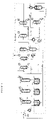
- the manufacturing process comprises six major unit operations.
- the relative positions of these six operation units are shown in Figures 1 and 2 .
- These operation units and/or the reactions therein, comprise:
- the reactor is constructed from materials which are resistant to the corrosive effects of the HF and HCl, such as Hastelloy-C, Inconel, Monel, Incalloy, or fluoropolymer-lined steel vessels.
- the reactor is equipped with an agitator. Such liquid-phase fluorination reactors are well known in the art.
- the reactor is further equipped with an optional rectifying column which permits the desired product to leave (along with by-product HCl, traces of light organics, e.g., principally 1234ze(E+Z), and sufficient anhydrous hydrogen fluoride (AHF) to form azeotropes), while retaining the bulk of the HF, plus under-fluorinated organics.
- AHF anhydrous hydrogen fluoride
- more than one fluorination reactors are connected in a series to increase throughput.
- the reaction is conducted in a train of agitated, temperature-controlled reactors, connected in a series and containing liquid reactants.
- One or more feeds comprising hydrogen fluoride and 1,1,1,3,3-penta-chloropropane or 1,1,1,3,3-pentachloropropane and/or 1,3,3,3-tetrachloropropene mixture enter the first reactor where they contact each other in a liquid phase.
- the resulting reaction produces a gas phase product comprising 1233zd(E) as well as various other by-products including HCl and possibly, 1233zd(Z).
- the gas phase product leaves the liquid phase reactor and enters an optional integrated rectifying column (operating in reflux mode) which permits the desired product to leave (along with by-product HCl, traces of light organics, e.g., principally 1234ze(E+Z), and anhydrous hydrogen fluoride in the amount greater than that needed to form the azeotropes), while retaining the bulk of the HF, plus under-fluorinated organics.
- the products exiting the top of the optional rectifying column are fed into HCl recovery system (3).
- the gas phase product leaves the liquid phase reactor and are fed into optional recycle column (2).
- the stream of under-fluorinated reaction products and unreacted HCC-240fa and HF is taken from the bottom of the first fluorination reactor and fed together with required amount of fresh HF to the second fluorination reactor that is operated similar to first fluorination reactor. In some embodiments more than two reactors are connected in the series.
- the stream from the bottom of the last fluorination reactor is optionally fed to the optional recycle column (2) or optionally recycled back to the first reactor (1).
- HF and HCC-240fa can be charged to the fluorination reactor and the reaction can be initiated immediately upon heating to the desired reaction temperature while maintaining agitation.
- the flow of HF to the first fluorination reactor can be resumed, and addition of the 1,1,1,3,3-pentachloropropane or 1,1,1,3,3-pentachloropropane and/or 1,3,3,3-tetrachloropropene mixture can be started immediately to cause continuous reaction.
- utilizing multiple fluorination reactors connected in a series HF can be fed to all of the agitated reactors to maintain proper ratio of HF to organics. Proper temperature control of the coolant and sufficient reflux action are desirable for optimum operation of the rectifying column to be effective.
- the gaseous stream exiting the top of each of the reactors or optional rectifying columns attached to the fluorination reactors comprising mainly 1233zd(E), 1233zd(Z), HF, and HCl (with some minor components including partially fluorinated intermediates and by-products, over-fluorinated by-products), then enters an optional recycle column or fed into HCl recovery system (3) directly.
- the stream of unreacted HF and HCC-240fa, under-fluorinated by-products from the bottom of last fluorination reactor is optionally also fed to the recycle column or optionally recycled back to the first reactor (1).
- a stream comprising mainly 1233zd(E), 1233zd(Z), HF, and HCl exits the top of the optional recycle column and enters HCl recovery column.
- the HCl formed continuously during the reaction is removed from the reactor due to its volatile nature, and flows through the attached distillation column without condensing.
- the material can then be purified and collected for sale (or further purification) by using a low-temperature HCl distillation column. High purity HCl is isolated and can be absorbed in deionized water as concentrated HCl for sale.
- the bottoms stream from the HCl removal column (3) that contains crude product mixture of 1233zd(E) and HF (in some embodiments about 30 wt%) is fed to a sulfuric extractor or a phase separator for removal of HF from this mixture.
- HF is either dissolved in the sulfuric acid or phase separated from the organic mixture.
- the HF is then desorbed from the sulfuric acid/HF mixture by stripping distillation and recycled back to the reactor.
- HF is phase-separated and recycled back to the reactor.
- the organic mixture either from the overhead of the sulfuric acid extractor or from the bottom layer of the phase separator may require treatment (scrubbing or adsorption) to remove traces of HF before it is fed to the next unit operation (5).
- Purification of final product preferably comprises two continuously operating distillation columns.
- the first column is used to remove light ends from the 1233zd(E) and the second column is used to remove the heavier components, primarily the 1233zd(Z), which is fed to an isomerization reactor, collected for further use or optionally recycled back to the reactor (2).
- the by-product 1233zd(Z) formed in the reaction and exiting the bottom of the second column is fed as a vapor to a reactor that contains an isomerization catalyst, preferably fluorinated chromium oxide.
- an isomerization catalyst preferably fluorinated chromium oxide.
- the by-product is converted to the desired product.
- the isomerization reactor exit stream is then recycled to (4) for purification.
- this step involves controlling the temperature of a heated surface to between 50°C to 350°C.
- the heated surface is contacted with the stream containing the 1233zd(Z) by-product.
- the feed stream is contacted with the heated surface for a period of time sufficient to convert at least a portion of the 1233zd(Z) to 1233zd(E) to produce a product stream rich in 1233zd(E).
- the heated surface includes the inside of a reactor vessel.
- the heated surface may include an outer surface of a packing material, for example a packing material that is packed in a reaction vessel.
- the reactor vessel is a continuous-type reactor vessel, for example a reactor vessel with a first opening and a second opening and a fluid pathway between the first and second openings.
- the feed stream is fed into the reactor vessel through the first opening and passes through the reactor vessel at a rate sufficient to isomerize the desired amount of 1233zd(Z).
- the resulting product stream exits the second opening.
- the reactor vessel is an elongate reactor vessel (e.g., a Monel TM tube) with the first opening at a first end and the second opening at a second end.
- the reactor vessel may be partially or entirely packed with packing material, for example with a stainless steel packing.
- the relatively large surface area of the packing material may facilitate the conversion reaction from the (Z) to the (E) isomer.
- Support structures that support the packing material may also be disposed in or on the reactor vessel.
- the packing material may be supported by a mesh or other structure that is disposed under, around, and/or within the packing material.
- the support structure may comprise the same material as the packing material, e.g., stainless steel (SS), nickel, or any other suitable material.
- the packing materials may also comprise one or more catalyst materials.
- suitable catalysts for the isomerization of 1233zd are metal oxides, halogenated metal oxides, Lewis acid metal halides, zero-valent metals, as well as combinations of these catalysts.
- Specific examples of suitable catalysts are AlF3, Cr2O3, fluorinated Cr2O3, zirconium oxide and halogenated versions thereof, or an aluminum oxide and halogenated versions thereof.
- the catalysts may be activated prior to use. Examples of activation procedures for several suitable catalysts may be found in U.S. Patent No. 7,563,936 .
- liquid phase agitated reactor R-1 is first charged with an required amounts of anhydrous hydrogen fluoride and 1,1,1,3,3-pentachloropropane or 1,1,1,3,3-pentachloropropane and/or 1,3,3,3-tetrachloropropene mixture.
- the reactor is constructed from materials which are resistant to the corrosive effects of the HF and HCl, such as Hastelloy-C, Inconel, Monel, Incalloy, or fluoropolymer-lined steel vessels.
- Such liquid-phase fluorination reactors are well known in the art. After the reactor is charged with HF and HCC-240fa an agitator is turned on to achieve a good agitation.
- reaction mixture is then heated to about 85°C to 150°C where the fluorination reaction between 1,1,1,3,3-pentachloropropane or 1,1,1,3,3-pentachloropropane and/or 1,3,3,3-tetrachloropropene mixture and HF is initiated.
- Continuous 1,1,1,3,3-pentachloropropane or 1,1,1,3,3-pentachloropropane and/or 1,3,3,3-tetrachloropropene mixture and HF (in a stoichiometric excess) feeds are simultaneously fed to heater HX-1 and then into a liquid phase reactor R-1.
- 1,1,1,3,3-pentachloropropane or 1,1,1,3,3-pentachloropropane and/or 1,3,3,3-tetrachloropropene mixture is fed directly into reactor R-1 and not through heater HX-1.
- the operating pressure of R-1 is in the range 75 psig (520 kPag) to 500 psig (3450 kPag) (preferably 185 psig [1280 kPag] to 400 psig [2760 kPag]) is maintained by a control valve on the reactor vapor exit or on the exiting flow from the optional rectifying column RC-1 and the reactor temperature is kept in the range of 65°C to 175°C (preferably 100°C to 140°C) primarily supplied by steam flow into the reactor jacket.
- a rectifying column RC-1 is optionally connected to the reactor, R-1, and serves the purpose of knocking down and returning some HF, partially fluorinated intermediates, and some unreacted 1,1,1,3,3-pentachloropropane or 1,3,3,3-tetrachloropropene back to the reactor for further reaction.
- the stream exiting the top of the reactor or the top of the optional rectifying column RC-1 comprising mainly 1233zd(E), 1233zd(Z), HF, and HCl (with some minor components including partially fluorinated intermediates and by-products, and over-fluorinated by-products), then enters optional recycle column D-1. If optional rectifying column RC-1 is employed the optional recycle column D-1 can be omitted.
- a stream of unreacted HF, unreacted 1,1,1,3,3-pentachloropropane, or 1,3,3,3-tetrachloropropene, and under-fluorinated intermediates is fed to second fluorination reactor R-2.
- the feed of fresh HF is also fed to R-2 to maintain proper HF to organics ratio.
- the second reactor R-2 is operated similar to R-1 and can be equipped with optional rectifying column RC-2 that is operated similar to RC-1.
- Reactor R-2 is maintained at temperature 115°C to 150°C and pressure of about 170 psig to 425 psig (1170 kPag to 2930 kPag).
- the stream exiting the top of the reactor R-2 or the top of the optional rectifying column RC-2 comprising mainly 1233zd(E), 1233zd(Z), HF, and HCl (with some minor components including partially fluorinated intermediates and by-products, and over-fluorinated by-products), then enters then enters optional recycle column D-1. If optional rectifying column RC-2 is employed the optional recycle column D-1 can be omitted.
- a stream of unreacted HF, unreacted 1,1,1,3,3-pentachloropropane or 1,3,3,3-tetrachloropropene, and under-fluorinated intermediates is fed to third fluorination reactor R-3.
- the feed of fresh HF is also fed to R-3 to maintain proper HF to organics ratio.
- Reactor R-3 is operated similar to R-1 and R-2 and can be equipped with optional rectifying column RC-3 that is operated similar to RC-1 and RC-2.
- Reactor R-3 is maintained at temperature 125°C to 160°C and pressure of about 160 psig to 450 psig (1100 kPag to 3100 kPag).
- the stream exiting the top of the reactor R-3 or the top of the optional rectifying column RC-3 comprising mainly 1233zd(E), 1233zd(Z), HF, and HCl (with some minor components including partially fluorinated intermediates and by-products, and over-fluorinated by-products), then enters then enters optional recycle column D-1. If optional rectifying column RC-3 is employed the optional recycle column D-1 can be omitted.
- a stream of unreacted HF, unreacted 1,1,1,3,3-pentachloropropane or 1,3,3,3-tetrachloropropene, and under-fluorinated intermediates is optionally fed to the recycle column D-1 or recycled back to the first reactor R-1 via vaporizer HX-1.
- this stream can be combined directly with the bottoms recycle stream from optional recycle stream D-1 back to reactor R-1 via vaporizer HX-1.
- heavy by-products are removed from this stream by establishing a small heavies purge continuous or intermittent side stream.
- the optional recycle column D-1 is operated in a such a way that a stream comprising mainly unreacted 1,1,1,3,3-pentachloropropane and/or 1,3,3,3-tetrachloropropene, partially fluorinated intermediates, and the majority of the HF exits the bottom of the recycle column and is recycled back to the liquid phase reactor R-1 via vaporizer HX-1.
- a stream comprising mainly 1233zd(E), 1233zd(Z), HF, and HCl exits the top of the recycle column and enters HCl column D-2.
- a stream comprising mainly HCl by-product exits the top of the HCl column and is fed to an HCl recovery system. The recovered HCl by-product can be sold for profit.
- the HCl column bottoms stream consisting mainly of 1233zd(E), 1233zd(Z), and HF are then fed into an HF recovery system.
- the HF recovery system starts with the crude 1233zd/HF stream being vaporized in heat exchanger HX-2 and fed into HF absorption column A-1.
- a liquid stream of 50% to 80% H2SO4 contacts the gaseous 1233zd/HF stream and absorbs the majority of the HF.
- the stream exiting the bottom of A-1 comprises HF/ H2SO4/H2O and is fed to heat exchanger HX-3 where it is heated to a temperature sufficient to flash the majority of the HF along with small amounts of H2O and H2SO4. This stream is fed to HF recovery distillation column D-2.
- HX-3 consisting mainly of H2SO4 and H2O (with 0% to 2% HF) is cooled in HX-4 and recycled back to HF absorption column A-1.
- the HF recovery column, D-3, bottoms stream comprising mainly H2SO4 and H2O are recycled back to heat exchanger HX-3.
- Anhydrous HF is recovered from the top of the HF recovery column, D-3, and is recycled back to the reactor R-1 via vaporizer HX-1.
- the stream exiting the top of HF absorption column A-1 comprising mainly 1233zd(E) and 1233zd(Z) (trace HF) is sent forward to a polishing system A-2 where the gaseous stream contacts a water or a caustic solution to remove trace HF and is subsequently dried with a desiccant.
- Acid free crude product exiting absorber A-2 is sent to the first of two purification columns, D-4.
- a stream exiting the top of the column D-4 consists mainly of reaction by-products that have boiling points lower than that of 1233zd(E).
- the stream exiting the bottom of lights column D-4 consisting mainly of 1233zd(E) and 1233zd(Z) and heavier by-products is fed to product recovery distillation column D-5.
- Product grade 1233zd(E) exits the top of the column to product storage.
- the product column bottoms consist mainly of 1233zd(Z) and reaction by-products with boiling points higher than that of 1233zd(E) is then fed to vaporizer HX-5 and then to isomerization reactor R-4 where by-product 1233zd(Z) is converted to the desired product.
- the stream leaving R-4 is then recycled to lights distillation column D-4 for purification.
- any by-products in the stream entering R-4 are unstable they may decompose and form small amounts of HF or HCl.
- the stream exiting R-4 can be recycled and combined with the stream entering the polishing system A-2 to remove the acid.
- the stream exiting the bottom of the product recovery distillation column, D-5 can be recycled back to first liquid phase reactor R-1.
- a heavies purge stream from the bottom of the product recovery distillation column, D-5 will be required to prevent build-up of high boiling impurities in the purification system. The heavies purge stream is collected for later use or waste disposal.
- liquid phase reactor R-1 is first charged with an required amounts of anhydrous hydrogen fluoride and 1,1,1,3,3-pentachloropropane or 1,1,1,3,3-pentachloro-propane and/or 1,3,3,3-tetra-chloropropene mixture.
- the reactor is constructed from materials which are resistant to the corrosive effects of the HF and HCl, such as Hastelloy-C, Inconel, Monel, Incalloy, or fluoro-polymer-lined steel vessels.
- Such liquid-phase fluorination reactors are well known in the art. After reactor is charged with HF and HCC-240fa an agitator is turned on to achieve a good agitation.
- reaction mixture is then heated to about 85°C to 150°C where the fluorination reaction between 1,1,1,3,3-pentachloropropane or 1,1,1,3,3-pentachloropropane and/or 1,3,3,3-tetrachloropropene mixture and HF is initiated.
- Continuous 1,1,1,3,3-pentachloropropane or 1,1,1,3,3-pentachloropropane and/or 1,3,3,3-tetrachloropropene mixture and HF (in a stoichiometric excess) feeds are simultaneously fed to heater HX-1 and then into a liquid phase reactor R-1.
- 1,1,1,3,3-pentachloropropane or 1,1,1,3,3-pentachloropropane and/or 1,3,3,3-tetrachloropropene mixture is fed directly into reactor R-1 and not through heater HX-1.
- the operating pressure of R-1 is in the range 75 psig (520 kPag) to 500 psig (3450 kPag) (preferably 185 psig [1280 kPag] to 400 psig [2760 kPag]) is maintained by a control valve on the exiting flow from the top of the reactor R-1 or optional rectifying column RC-1 and the reactor temperature is kept in the range of 65°C to 175°C (preferably 100°C to 140°C) primarily supplied by steam flow into the reactor jacket.
- a rectifying column RC-1 is optionally connected to the reactor, R-1, and serves the purpose of knocking down and returning some HF, partially fluorinated intermediates, and some unreacted 1,1,1,3,3-pentachloropropane or 1,3,3,3-tetrachloropropene back to the reactor for further reaction.
- the stream exiting the top of the reactor or the top of the optional rectifying RC-1 comprising mainly 1233zd(E), 1233zd(Z), HF, and HCl (with some minor components including partially fluorinated intermediates and by-products, and over-fluorinated by-products), then enters optional recycle column D-1. If optional rectifying column RC-1 is employed the optional recycle column D-1 can be omitted.
- a stream of unreacted HF, unreacted 1,1,1,3,3-pentachloropropane or 1,3,3,3-tetrachloropropene, and under-fluorinated intermediates is fed to second fluorination reactor R-2.
- the feed of fresh HF is also fed to R-2 to maintain proper HF to organics ratio.
- the second reactor R-2 is operated similar to R-1 and can be equipped with optional rectifying column RC-2 that is operated similar to RC-1.
- Reactor R-2 is maintained at temperature 115°C to 150°C and pressure of about 170 psig to 425 psig (1170 kPag to 2930 kPag).
- the stream exiting the top of the reactor R-2 or the top of the optional rectifying column RC-2 comprising mainly 1233zd(E), 1233zd(Z), HF, and HCl (with some minor components including partially fluorinated intermediates and by-products, and over-fluorinated by-products), then enters then enters recycle column D-1. If optional rectifying column RC-2 is employed the optional recycle column D-1 can be omitted.
- a stream of unreacted HF, unreacted 1,1,1,3,3-pentachloropropane or 1,3,3,3-tetrachloropropene, and under-fluorinated intermediates is fed to third fluorination reactor R-3.
- the feed of fresh HF is also fed to R-3 to maintain proper HF to organics ratio.
- Reactor R-3 is operated similar to R-1 and R-2 and can be with optional rectifying column RC-3 that is operated similar to RC-1 and RC-2.
- Reactor R-3 is maintained at a temperature of 125°C to 160°C and pressure of about 160 psig to 450 psig (1100 kPag to 3100 kPag).
- the stream exiting the top of the reactor R-3 or the top of the optional rectifying column RC-3 comprising mainly 1233zd(E), 1233zd(Z), HF, and HCl (with some minor components including partially fluorinated intermediates and by-products, and over-fluorinated by-products), then enters then enters recycle column D-1. If optional rectifying column RC-3 is employed the optional recycle column D-1 can be omitted.
- a stream of unreacted HF, unreacted 1,1,1,3,3-pentachloropropane or 1,3,3,3-tetrachloropropene, and under-fluorinated intermediates is optionally fed to the recycle column D-1 or recycled back to the first reactor R-1 via vaporizer HX-1.
- this stream can be combined directly with the bottoms recycle stream from optional recycle stream D-1 back to reactor R-1 via vaporizer HX-1.
- heavy by-products are removed from this stream by establishing a small heavies purge continuous or intermittent side stream.
- the recycle optional column D-1 is operated in a such a way that a stream comprising mainly unreacted 1,1,1,3,3-pentachloropropane and/or 1,3,3,3-tetrachloropropene, partially fluorinated intermediates, and the majority of the HF exits the bottom of the recycle column and is recycled back to the liquid phase reactor R-1 via vaporizer HX-1.
- a stream comprising mainly 1233zd(E), 1233zd(Z), HF, and HCl exits the top of the recycle column and enters HCl column D-2.
- a stream comprising mainly HCl by-product exits the top of the HCl column and is fed to an HCl recovery system. The recovered HCl by-product can be sold for profit.
- the HCl column bottoms stream consisting mainly of 1233zd(E), 1233zd(Z), and HF are then fed into an HF recovery system.
- the HF recovery system starts with the 1233zd/HF stream being fed into heat exchanger HX-2 where it is pre-cooled to temperatures below 0°C and then enters phase separation vessel PS-1. Here the stream temperature is maintained or further cooled to -40°C to 0°C.
- the HF rich top layer (less than 10% 1233zd) is recycled back to the liquid phase reactor R-1.
- the organic rich bottom layer containing mainly 1233zd (less than 4% HF) is sent to vaporizer HX-3 and then forward to a polishing system A-1 where the gaseous stream contacts water or a caustic solution to remove trace HF and is subsequently dried with a desiccant.
- Acid free crude product exiting absorber A-1 is sent to the first of two purification columns, D-3.
- a stream exiting the top of the column D-3 consists mainly of reaction by-products that have boiling points lower than that of 1233zd(E).
- the stream exiting the bottom of lights column D-3 consisting mainly of 1233zd(E) and 1233zd(Z) and heavier by-products is fed to product recovery distillation column D-4.
- Product grade 1233zd(E) exits the top of the column to product storage.
- the product column bottoms consist mainly of 1233zd(Z) and reaction by-products with boiling points higher than that of 1233zd(E) is then fed to vaporizer HX-4 and then to isomerization reactor R-4 where by-product 1233zd(Z) is converted to the desired product.
- the stream leaving R-4 is then recycled to lights distillation column D-3 for purification.
- any by-products in the stream entering R-4 are unstable they may decompose and form small amounts of HF or HCl.
- the stream exiting R-4 can be recycled and combined with the stream entering the polishing system A-1 to remove the acid.
- the stream exiting the bottom of the product recovery distillation column, D-4 can be recycled back to first liquid phase reactor R-1.
- a heavies purge stream from the bottom of the product recovery distillation column, D-4 will be required to prevent build-up of high boiling impurities in the purification system.
- the heavies purge stream is collected for later use or waste disposal.
- the organic remaining in the reactor after venting was recovered by quenching the reactor with about 300 to 400 grams of water to absorb HF and HCl, and then adding about 100 grams of carbon tetrachloride. The reactor was then opened and its contents discharged into a plastic bottle. The organic was separated from the aqueous phase by use of a separatory funnel. The amount of heavies collected from the reactor was calculated by subtracting the weight of CCl4 added to the reactor from the total weight of organic phase collected and amounted to 96.9 grams.
- Example 1 The experiment described in Example 1 was repeated using the same equipment and procedure. The reactor was heated to 110°C and held. However, the experiment was not allowed to go to completion. The experiment was called Exp #5. After about 6.5 hrs. the reactor pressure reached 320 psig (2210 kPag) and the experiment was stopped. 382.7 grams of HF and 244.1 grams of HCC-240fa were initially charged to the reactor. Results are similar to those of Example 1, but with a lower conversion of HCC-240fa.
- HCC-240fa After venting the pressure (HCl) resulting from the reaction of HF with the catalyst, 233.6 grams of HCC-240fa was charge to reactor. The mixer was then turned on ensuring the reactor contents were well mixed. Then the reactor was heated to the desired temperature. Upon heating the pressure began to rise as HCl by product was produced as a result of a fluorination reaction. The pressure was controlled in the range of 200 psig to 230 psig (1380 kPag to 1520 kPag) by venting off the HCl generated in the reaction to a dry-ice chilled trap (DIT). The reactor was held at 60°C to 80°C for about 8.5 hours (note the lower temperature required when using a catalyst).
- DIT dry-ice chilled trap
- This example illustrates the initial reactor running in continuous mode.
- Experiments were performed in a 1-gallon (4 L) agitated Parr reactor equipped with 2" (5 cm)-ID x 8-feet (2 metre) column filled with 1/4" (0.6 cm) ProPak packing and a tube-in-tube condenser.
- the reactor was heated by external 1.5 kW electric heater and the condenser was cooled by water.
- Reactor pressure was controlled by venting reactor products to caustic scrubber (10wt% KOH circulating at 55°C) and then collecting in a chilled product collection cylinder.
- 240fa was fed to the vapor space of the reactor and HF was fed via dip-tube to the bottom of the reactor to facilitate mixing of the reactants.
- 240fa feed was introduced at 0.62 lbs/hr (0.28 kg/hr) after the reactor was heated to about 105°C.
- Introduction of 240fa feed resulted in a pressure increase in the reactor indicating the initiation of the fluorination reaction and formation of HCl.
- 2.5 hours after 240fa feed was introduced into the reactor pressure reached 400 psig (2760 kPag) with the corresponding reactor temperature of 139°C.
- the steady collection rate was achieved after about 1 to 2 hours at the reaction pressure.
- HF feed was introduced into the reactor at the rate 0.3 to 0.6 lbs/hr (0.1 to 0.3 kg/hr) in order to maintain the reactor weight.
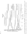
- Reaction system parameters are presented in Figure 6 .
- the reaction was stopped after 48 hours on-stream.
- the reactor contents were sampled and no organics was found in the reactor.
- During 48 hours of the reaction we accumulated about 2 additional lbs (0.9 kg) of HF.
- the excess HF was vented to the scrubber bringing the HF inventory in the reactor to 3 lbs (1 kg).
- reaction was re-started at 400 psig (2760 kPag) pressure.
- the reactor was heated to about 107°C and 240fa feed was started at 0.6 lbs/hr (0.3 kg/hr) and after about 2.5 hours the reactor temperature reached 140°C and reaction pressure stabilized at 400 psig (2760 kPag).
- the 240fa feed rate was maintained at 0.6 lbs/hr (0.3 kg/hr) and HF feed rate was maintained at 0.4 lbs/hr (0.2 kg/hr).
- the reactor temperature was about 139°C to 140°C and the temperature at the top of the column was about 117°C to 120°C.
- the 240fa feed rate was increased to 1.0 lbs/hr (0.45 kg/hr) and HF feed rate was increased to about 0.7 lbs/hr (0.3 kg/hr). Again product collection rate increased almost immediately after feed rates were increased. The reactor weight stayed constant. At about 72 hours on-stream 240fa feed rate was further increased to 1.25 lb/hr (0.570 kg/hr) and HF feed rate was increased to about 0.85 lb/hr (0.39 kg/hr) to maintain reactor weight. Once again product collection rate increased almost immediately after feed rates were increased. The reactor temperature stabilized at about 137.5°C and temperature at the top of the column stabilized at about 115°C to 118°C. The 240fa and HF feed were stopped after 79 hours on-stream. About 10 minutes after feeds were stopped system pressure started to decrease and reactor started to warm up indicating the completion of the reaction.
- Reaction system parameters are presented in Figure 6 and the analysis of the reaction products at different feed rates presented in the Table IV below.
- a series of three continuously stirred reactors with attached rectifying columns is used to produce crude 1233zd(E) crude product. There is a bottom drain on the first reactor that feeds the second reactor and a drain on the second reactor that feeds the third reactor.
- the overhead stream that exits each of the three rectifying columns are connected to combine all 1233zd(E) crude and HCl produced and fed forward for separation into individual components.
- HF 15:1 mole ratio of HF:HCC-240fa.
- the reactor temperature is maintained at about 140°C.
- the reactor pressure is controlled at about 400 psig (2760 kPag).
- HF, HCl, and crude 1233zd(E) exit the top of the attached rectifying column continuously.
- the reactor is drained continuously to the 2nd reactor at a rate that maintains a near constant level in the reactor.
- the lead reactor achieves a 70% conversion of HCC-240fa and a yield of 50% of 1233zd(E) crude.
- the organic composition of the material being drained to the 2nd reactor is about 40% HCC-240fa, 55% HCFC-241fa, and 5% HCFC242fa.
- HF is also present in this stream. Fresh HF is added to the 2nd reactor to make up for rectifier column overhead losses.
- the second reactor is run at a 375 psig (2590 kPag) and is maintained at 135°C. HF, HCl, and crude 1233zd(E) exit the top of the attached rectifying column continuously.
- the second reactor is drained continuously to the third reactor at a rate that maintains a near constant level in the reactor.
- the second reactor achieves a 90% conversion of HCC-240fa and a yield of 70% of 1233zd(E) crude.
- the organic composition of the material being drained to the second reactor is about 33% HCC-240fa, 62% HCFC-241fa, and 5% HCFC242fa.
- HF is also present in this stream. Fresh HF is added to the 3rd to make up for rectifier column overhead losses.
- the third reactor is run at a 350 psig (2410 kPag) and is maintained at 130°C. HF, HCl, and crude 1233zd(E) exit the top of the attached rectifying column continuously.
- the third reactor is drained continuously to a recycle column at a rate that maintains a near constant level in the reactor.
- the third reactor achieves a 100% conversion of HCC-240fa and a yield of 95% of 1233zd(E) crude.
- the organic composition of the material being drained to the recycle column is about 95% HCFC-241fa, and 5% HCFC-242fa.
- HF is also present in this stream.
- This example illustrates the recovery of anhydrous HF from a mixture of HF and HCFO-1233zd according to certain preferred embodiments of the present invention.
- a mixture consisting of about 70 wt.% HCFO-1233zd(E) crude and about 30 wt.% HF is vaporized and fed to the bottom of a packed column at a feed rate of about 2.9 lbs (1.3 kg) per hour for about 4 hours.
- a stream of about 80 wt.% sulfuric acid (80/20 H2SO4/H2O) with about 2% HF dissolved therein is fed continuously to the top of the same packed column at a feed rate of about 5.6 lbs (2.5 kg) per hour during the same time frame.
- a gaseous stream exiting the top of the column comprises HCFO-1233zd(E) crude with less than 1.0 wt.% HF therein.
- the concentration of HF in the sulfuric acid in the column bottoms increases from 2.0 wt.% to about 15 wt.%.
- the column bottoms containing sulfuric acid and about 15 wt.% HF is collected and charged into a two gallon (8 L) Teflon ® vessel.
- the mixture is heated to about 140°C to vaporize and flash off HF product, which is collected.
- the collected HF product contains about 6000 ppm water and 500 ppm sulfur.
- the sulfuric acid contains about 500 ppm of TOC (total organic carbon).
- the HF collected from flash distillation is distilled in a fractionation distillation column and anhydrous HF is recovered.
- the recovered anhydrous HF contains less than 50 ppm of sulfur impurities and less than 100 ppm water.
- This example demonstrates the purification of the acid free 1233zd(E) crude product.
- About 92 lbs (42 kg) of acid free 1233zd crude material produced in Example 2 was charged to a batch distillation column.
- the crude material contained about 94 GC area% 1233zd(E) and 6 GC area% impurities.
- the distillation column consisted of a ten gallon (38 L) reboiler, two inch (5 cm) inner diameter (ID) by ten feet (3 metre) propack column, and a shell and tube condenser.
- the column had about 30 theoretical plates.
- the distillation column was equipped with temperature, pressure, and differential pressure transmitters.
- a representative 1233zd(E) liquid phase reactor effluent mixture as determined in Example 2 is charged into a batch distillation column.
- the distillation column consists of a ten gallon (38 L) reboiler, two inch (5 cm) ID by ten feet (3 metre) propack column, and a shell and tube condenser with -40°C coolant flow capability.
- the column has about 30 theoretical plates.
- the distillation column is equipped with temperature, pressure, and differential pressure transmitters.
- the distillation column feed mixture is about 30 wt% HF, 37 wt% HCl and 33% 1233zd(E) crude.
- the distillation is run at a pressure of about 100 psig (689 kPag) and a differential pressure (delta P) of 15 to 20 inches of water (3.7 to 5.0 kPa). Both the distillate and reboiler are sampled periodically and analyzed for organic, HF, and HCl using gas and ion chromatography.
- HCl, organic, and HF are observed in both samples.
- concentration of the reboiler changes.
- concentration of HCl decreases until it is undetectable.
- the distillation is allowed to proceed until the concentration of organic in the reboiler sample decreases to only trace amounts as analyzed using gas chromatography.
- the material remaining in the reboiler is essentially pure HF.
- the recovered HF (reboiler bottoms) is then used to demonstrate recycle of recovered HF back to the liquid phase fluorination reactor and works satisfactorily.
- This example demonstrates the HF recovery by phase separation. It was visually observed using a Teflon ® cylinder that HF and 1233zd(E) form a heterogeneous mixture. The phase-separation of a mixture containing 1233zd(E) and HF was performed in the temperature range of -20°C to +0°C.
- a 500 ml stainless steel (SS) sample cylinder was used for the study. The temperature of the cylinder was controlled with ethanol circulating through the coil wrapped around the cylinder. A thermocouple was attached to the outside wall of the cylinder (between cooling coil and the cylinder wall) and positioned in the middle of the cylinder to measure the temperature.
- the SS cylinder was also equipped with sampling valves at the bottom and the top of the cylinder.
- This example demonstrates the isomerization of 1233zd(Z) into desired product 1233zd(E).
- Conversion of 1233zd(Z) into 1233zd(E) was performed using a Monel TM reactor (ID two inch [5 cm], length 32 inch [81 cm]) equipped with a Monel TM preheater (ID one inch [5 cm], length 32 inch [81 cm]) which was filled with Nickel mesh to enhance heat transfer.
- the reactor was filled with 1.5 L of pelletized fluorinated Cr2O3 catalyst. Nickel mesh was placed at the top and at the bottom of reactor to support the catalyst. A multi-point thermocouple was inserted at the center of the reactor.
- a feed containing about 10.0 wt% 1233zd(E) and 86.3 wt% 1233zd(Z) was introduced into the reactor at the rate of 0.7 lb/hr (0.3 kg/hour).
- the feed was vaporized prior to entering the reactor preheater.
- the reactor temperature for this experiment was varied between 100°C and 200°C. The temperature gradient throughout the reactor never exceeded 3°C to 5°C. Samples of reaction products were taken every hour and GC analysis of those samples is given in Table VI.
Description
- This invention relates to methods and systems for producing hydrochloro-fluoroolefins, particularly trans-1-chloro-3,3,3-trifluoropropene (HCFO-1233zd(E)).
- Chlorofluorocarbon (CFC) based chemicals have been widely used in industry in a variety of different applications including as refrigerants, aerosol propellants, blowing agents and solvents, among others. However, certain CFCs are suspected of depleting the Earth's ozone layer. Accordingly, more environmentally friendly substitutes have been introduced as replacements for CFCs. For example, 1,1,1,3,3-pentafluoropropane (HFC-245fa) is recognized as having favorable physical properties for certain industrial applications, such as foam blowing agents and solvents, and therefore is consider to be a good substitute for the CFCs previously used for these applications. Unfortunately, the use of certain hydrofluorocarbons, including HFC-245fa, in industrial applications is now believed to contribute to the global warming. Accordingly, more environmentally friendly substitutes for hydrofluorocarbons are now being sought.
- The compound 1-chloro-3,3,3-trifluoropropene, also known as HCFO-1233zd or simply 1233zd, is a candidate for replacing HFC-245fa in some applications, including uses as blowing agents and solvents. HCFO-1233zd has a cis or Z-isomer and a trans or E- isomer. Due to differences in the physical properties between these two isomers, pure 1233zd(E), pure 1233zd(Z), or certain mixtures of the two isomers may be suitable for particular applications as refrigerants, propellants, blowing agents, solvents, or for other uses.
- Processes for synthesizing 1233zd are known. For example,
WO 97/24307 -
U.S. Patent No. 6,844,475 describes a catalyzed liquid phase reaction of HCC-240fa with HF to produce 1233zd in higher yields. However the presence of the fluorination catalyst promotes the formation of heavy by-products, oligomers, and tars which build up in the reactor over time and lead to catalyst dilution and catalyst deactivation, resulting in loss of productivity due to excessive downtime to remove these by-products from the reactor on a periodic basis. -
WO2010059496A1 discloses a process for preparing trans 1-chloro-3,3,3-trifluoropropene (E-1233zd) that comprises at least one step of isomerization of cis 1-chloro-3,3,3-trifluoropropene to trans 1-chloro-3,3,3-trifluoropropene. - Known catalytic methods for the production of 1233zd(E) from a liquid phase reaction typically suffer from low yields due to excessive heavies formation caused by the presence of the fluorination catalyst. Accordingly, there remains a need for a process for producing 1233zd(E) in high yields. This invention satisfies that need.
- The present invention solves the problem faced by catalytic reactions for the production of 1233zd(E) by conducting a continuous reaction without the use of a catalyst. One drawback of not using a catalyst is the problem of slower reaction rates. The present invention overcomes this problem by the use of a method comprising the steps of:
- (a) operating one agitated reaction vessel or a series of more than one agitated reaction vessel, each vessel in succession converting a portion of the original reactants fed to the first of the reaction vessels, with all of the reaction vessels being run simultaneously and operating in a continuous fashion;
- (b) conducting, in each of the reaction vessels, a series of fluorination reactions of a starting material selected from the group consisting of 1,1,1,3,3-pentachloropropane and 1,3,3,3-tetrachloropropene, and any mixtures thereof, using HF without the use of a catalyst and with simultaneous removal of by-product HCl and the product (E)1-chloro-3,3,3-trifluoropropene, wherein each reaction vessel is maintained at a temperature range of 65°C to 175°C;
- (c) recycling at least a portion of (i) unreacted starting material, (ii) HF and (iii) under-fluorinated by-products back to step (b);
- (d) separating and purifying by-product HCl;
- (e) separating excess HF back to step (b);
- (f) purifying the desired product, (E)1-chloro-3,3,3-trifluoropropene; and
- (g) isomerization of any by-product (Z)1-chloro-3,3,3-trifluoropropene to (E)1 chloro-3,3,3-trifluoropropene to maximize the process yield.
- The number of reactors employed in a train of reactors is determined by their size and the desired production rate. If larger reactors are used, fewer may be required to achieve a desired production rate. If smaller reactors are used, more may be required to achieve a comparable production rate.
- As an non-limiting example, the lead reactor converts 70% of the 240fa fed of which only 50% is converted to the desired product while, the rest is only partially fluorinated to intermediates including for example, HCFC-241fa, HCFO-1231zd, HCFC-242fa, HCFO-1232zd and HCFC-243fa. Any unconverted HCC-240fa and under-fluorinated intermediates are high boiling compounds relative to 1233zd(E) and will not easily exit the attached rectifying column.
- A continuous stream containing at least a portion of unconverted HCC-240fa, under-fluorinated intermediates, and some unreacted HF are taken from the bottom of the reactor and fed to a second reactor. Here more of the original reactants and intermediates are converted to 1233zd(E) which exits the top of the attached rectifying column. Fresh HF may be added as required.
- As before, a continuous stream of at least a portion of unconverted HCC-240fa, under-fluorinated intermediates, and some unreacted HF are taken from the bottom of the second reactor and fed to a third reactor where more is converted. Again fresh HF may need to be added. This reactor train continues in series until the desired production rate of 1233zd(E) is achieved.
- Another embodiment of the invention provides a method for producing (E)1-chloro-3,3,3-trifluoropropene in one agitated reaction vessel or a series of more than one agitated reaction vessel, comprising the following steps:
- (a) providing a liquid reaction admixture in at least one of the reaction vessels, comprising hydrogen fluoride and a reactant composition selected from the group consisting of 1,1,1,3,3-pentachloropropane, 1,3,3,3-tetrachloropropene, and any mixtures thereof, wherein the hydrogen fluoride and the reactant composition are present in a molar ratio of greater than 3:1;
- (b) reacting the hydrogen fluoride and the reactant composition in a liquid phase without the use of a catalyst using one agitated reactor or more than one agitated reactors in series, wherein each vessel is maintained at a temperature range of 65°C to 175°C, to produce one or more reaction product streams selected from the group consisting of (E) 1-chloro-3,3,3-trifluoro-propene, hydrogen chloride, hydrogen fluoride, (Z) 1-chloro-3,3,3-trifluoropropene and unreacted compounds of the reactant composition and/or under fluorinated intermediates, wherein each reaction product stream has a weight ratio of (E) 1-chloro-3,3,3-trifluoropropene to (Z) 1-chloro-3,3,3-trifluoropropene of greater than 1; and
- (c) wherein optionally, each individual reaction vessel in the series can be equipped with a rectifying column that returns some of the unreacted HF, and the majority of unreacted 1,1,1,3,3-pentachloropropane, and/or 1,3,3,3-tetrachloropropene and/or under-fluorinated intermediates (e.g., 1,1,3,3-tetrachloro-1-fluoropropane (241fa), 1,1,3,3-tertachloro-3-fluoropropene (1231zd), 1,1,3-trichloro-1,1-difluoropropane (242fa), 1,1,3-trichloro-3,3-difluoropropene (1232zd), 1,1-dichloro-3,3,3-trifluoropropane (243fa) back to the reaction vessel;
- (d) combining the one or more resulting reaction product streams into a single combined reaction product stream;
- (e) contacting the combined reaction product stream with a recycle column to produce:
- (i) a first crude product stream comprising a majority of the hydrogen chloride, a majority of the (E) 1-chloro-3,3,3-trifluoropropene, optionally a majority of the (Z) 1-chloro-3,3,3-trifluoropropene, and at least a portion of the unreacted hydrogen fluoride, wherein the portion is an amount greater than the amount needed to form an azeotrope with one or more of the (E) 1-chloro-3,3,3-trifluoropropene and the (Z) 1-chloro-3,3,3-trifluoropropene, and
- (ii) a bottom component comprising a majority of the unreacted hydrogen fluoride and unreacted compounds of the reactant composition and/or under fluorinated intermediates; and
- (f) returning the bottom component to the reaction admixture.
- In certain preferred embodiments, the method further comprises one or more of the following additional steps:
- (g) separating unreacted reactants, including unreacted 1,1,1,3,3 -pentachloropropane, and/or 1,1,3,3-tetrachloropropene and/or 1,3,3,3-tetrachloropropene and/or under-fluorinated intermediates (e.g., 1,1,3,3-tetrachloro-1-fluoropropane (241fa), 1,1,3,3-tertachloro-3-fluoropropene (1231zd), 1,1,3-trichloro-1,1-difluoropropane (242fa), 1,1,3-trichloro-3,3-difluoropropene (1232zd), 1,1-dichloro-3,3,3-trifluoro-propane (243fa),) via distillation and recycling these unreacted reactants and under-fluorinated intermediates back to the reactor; this is achieved either in step (c) or (e), or both;
- (h) removing at least a portion, and preferably a majority, of hydrochloric acid by-product via distillation;
- (i) separating and recycling unreacted HF in a crude product stream via a sulfuric acid adsorption or a phase separation;
- (j) further removing the residual acid in a crude product by the steps of polishing by a water or weak caustic absorption and drying;
- (k) distillation of the crude product stream to separate 1233zd(E) from reaction by-products; and
- (1) isomerization of 1233zd(Z) by-products to form 1233zd(E).
-
-
Figure 1 shows a schematic depiction of processing equipment used in an integrated liquid phase synthesis of 1233zd(E) according to a preferred embodiment of the invention. -
Figure 2 shows a schematic depiction of processing equipment used in an integrated liquid phase synthesis of 1233zd(E) according to another preferred embodiment of the invention. -
Figure 3 illustrates the reaction pressure and temperature profiles that were observed during Experiment 3 (no catalyst) in a one gallon (4 L) Parr reactor. -
Figure 4 illustrates the reaction pressure and temperature profiles that were observed during Experiment 5 (no catalyst) in a one gallon Parr (4 L) reactor. -
Figure 5 illustrates the reaction pressure and temperature profiles that were observed during Experiment 4 (catalyst) in a one-gallon (4 L) Parr reactor. -
Figure 6 illustrates the reactor system conditions observed during the experiment described in Example 3. - The invention involves a fully integrated manufacturing process for making (E) 1 -chloro-3,3,3-trifluoropropene, as described below.
- The reaction chemistry for this process involves a single-step reaction of 1,1,1,3,3-pentachloropropane, or 1,1,1,3,3-pentachloropropane and/or 1,3,3,3-tetrachloropropene mixture with anhydrous HF in a liquid-phase, uncatalyzed agitated reactor to produce primarily (E) 1-chloro-3,3,3-trifluoropropene (1233zd(E)) plus HCl as a by-product. Preferably, the reaction is maintained under conditions (temperature, pressure, residence time) to increase the relative ratio of (E) to (Z) isomers of 1233zd while also minimizing the reaction of HF with the resulting 1233zd(E) which would lead to the formation of HFC-244fa, which in turn can react further to produce HFO-1234ze. Accordingly, the desired reactions involve:
CCl3CH2CHCl2 + 3HF → CF3CH=CHCl + 4HCl
CCl3CH=CHCl + 3 HF → CF3CH=CHCl + 3HCl
- Undesired reactions, which are preferably avoided, include:
CCl3CH2CHCl2 + 3 HF → CF3CH=CHCl + 4 HCl, 1,1,1,3,3-pentachloropropane 1233zd(Z)
CF3CH=CHCl + HF → CF3CH2CHFCl (E or Z) 1233zd 244fa
CF3CH2CHFCl + HF → CF3CH2CF2 + HCl 244fa 245fa
CF3CH2CHFCl → CF3CH=CHF + HCl and 244fa 1234ze
CF3CH=CHF + HF → CF3CH2CF2. 1234ze 245fa
- The manufacturing process comprises six major unit operations. The relative positions of these six operation units are shown in
Figures 1 and2 . These operation units and/or the reactions therein, comprise: - (1)
- (a) operating one agitated reaction vessel or a series of more than one agitated reaction vessel, each vessel in succession converting a portion of the original reactants fed to the first of the reaction vessels, with all of the reaction vessels being run simultaneously and operating in a continuous fashion;
- (b) conducting, in each of the reaction vessels, a series of fluorination reactions of a starting material selected from the group consisting of 1,1,1,3,3-pentachloropropane and 1,3,3,3-tetrachloropropene, and any mixtures thereof, using HF without the use of a catalyst and with simultaneous removal of by-product HCl and the product (E)1-chloro-3,3,3-trifluoropropene, wherein each reaction vessel is maintained at a temperature range of 65°C to 175°C;
- (2) recycle of at least a portion of (i) unreacted HCC-240fa, (ii) HF and (iii) under-fluorinated by-products back to (1),
- (3) separation and purification of by-product HCl,
- (4) separation of excess HF back to (1),
- (5) purification of final product, 1233zd(E), and
- (6) isomerization of by-product 1233zd(Z) to 1233zd(E) to maximize the process yield.
- Preferably the reactor is constructed from materials which are resistant to the corrosive effects of the HF and HCl, such as Hastelloy-C, Inconel, Monel, Incalloy, or fluoropolymer-lined steel vessels. The reactor is equipped with an agitator. Such liquid-phase fluorination reactors are well known in the art. The reactor is further equipped with an optional rectifying column which permits the desired product to leave (along with by-product HCl, traces of light organics, e.g., principally 1234ze(E+Z), and sufficient anhydrous hydrogen fluoride (AHF) to form azeotropes), while retaining the bulk of the HF, plus under-fluorinated organics.
- In preferred embodiments more than one fluorination reactors are connected in a series to increase throughput. In a preferred embodiment, the reaction is conducted in a train of agitated, temperature-controlled reactors, connected in a series and containing liquid reactants. One or more feeds comprising hydrogen fluoride and 1,1,1,3,3-penta-chloropropane or 1,1,1,3,3-pentachloropropane and/or 1,3,3,3-tetrachloropropene mixture enter the first reactor where they contact each other in a liquid phase. The resulting reaction produces a gas phase product comprising 1233zd(E) as well as various other by-products including HCl and possibly, 1233zd(Z).
- The gas phase product leaves the liquid phase reactor and enters an optional integrated rectifying column (operating in reflux mode) which permits the desired product to leave (along with by-product HCl, traces of light organics, e.g., principally 1234ze(E+Z), and anhydrous hydrogen fluoride in the amount greater than that needed to form the azeotropes), while retaining the bulk of the HF, plus under-fluorinated organics. The products exiting the top of the optional rectifying column are fed into HCl recovery system (3). Optionally, the gas phase product leaves the liquid phase reactor and are fed into optional recycle column (2).
- The stream of under-fluorinated reaction products and unreacted HCC-240fa and HF is taken from the bottom of the first fluorination reactor and fed together with required amount of fresh HF to the second fluorination reactor that is operated similar to first fluorination reactor. In some embodiments more than two reactors are connected in the series. The stream from the bottom of the last fluorination reactor is optionally fed to the optional recycle column (2) or optionally recycled back to the first reactor (1).
- HF and HCC-240fa can be charged to the fluorination reactor and the reaction can be initiated immediately upon heating to the desired reaction temperature while maintaining agitation. The flow of HF to the first fluorination reactor can be resumed, and addition of the 1,1,1,3,3-pentachloropropane or 1,1,1,3,3-pentachloropropane and/or 1,3,3,3-tetrachloropropene mixture can be started immediately to cause continuous reaction.
- In some embodiments utilizing multiple fluorination reactors connected in a series HF can be fed to all of the agitated reactors to maintain proper ratio of HF to organics. Proper temperature control of the coolant and sufficient reflux action are desirable for optimum operation of the rectifying column to be effective. General operating conditions which we have found to work well for the reaction and optional rectifying column are: Operating pressure of 100 to 500 psig (689 to 3450 kPag) maintained by a control valve on the exiting flow from the rectifying column; reactor temperature of 65°C to 175°C, primarily supplied by steam flow into the reactor jacket; application of -40°C to 35°C brine cooling to the heat exchanger on top of the rectifying column to induce reflux; temperature in the center portion of the stripper about 5°C to 60°C below that in the reactor; additional heat input by superheating the HF feed with highpressure steam to 70°C to 180°C.
- It has been discovered that maintaining the reaction under the operating conditions, particularly, a temperature range of 65°C to 175°C, more preferably 85°C to 155°C, and most preferably 95°C to 150°C, produces a high ratio of 1233zd(E) to 1233zd(Z).
- The gaseous stream exiting the top of each of the reactors or optional rectifying columns attached to the fluorination reactors comprising mainly 1233zd(E), 1233zd(Z), HF, and HCl (with some minor components including partially fluorinated intermediates and by-products, over-fluorinated by-products), then enters an optional recycle column or fed into HCl recovery system (3) directly. The stream of unreacted HF and HCC-240fa, under-fluorinated by-products from the bottom of last fluorination reactor is optionally also fed to the recycle column or optionally recycled back to the first reactor (1).
- A stream comprising mainly unreacted 1,1,1,3,3-pentachloropropane and/or 1,3,3,3-tetrachloropropene, partially fluorinated intermediates, and the majority of the HF exits the bottom of the recycle column and is recycled back to the first liquid phase reactor. Optionally it can be fed to any of the reactor in the series. A stream comprising mainly 1233zd(E), 1233zd(Z), HF, and HCl exits the top of the optional recycle column and enters HCl recovery column.
- The HCl formed continuously during the reaction is removed from the reactor due to its volatile nature, and flows through the attached distillation column without condensing. The material can then be purified and collected for sale (or further purification) by using a low-temperature HCl distillation column. High purity HCl is isolated and can be absorbed in deionized water as concentrated HCl for sale.
- The bottoms stream from the HCl removal column (3) that contains crude product mixture of 1233zd(E) and HF (in some embodiments about 30 wt%) is fed to a sulfuric extractor or a phase separator for removal of HF from this mixture. HF is either dissolved in the sulfuric acid or phase separated from the organic mixture. For embodiments utilizing a sulfuric acid adsorption system, the HF is then desorbed from the sulfuric acid/HF mixture by stripping distillation and recycled back to the reactor. For embodiments utilizing a phase separator, HF is phase-separated and recycled back to the reactor. The organic mixture either from the overhead of the sulfuric acid extractor or from the bottom layer of the phase separator may require treatment (scrubbing or adsorption) to remove traces of HF before it is fed to the next unit operation (5).
- Purification of final product preferably comprises two continuously operating distillation columns. The first column is used to remove light ends from the 1233zd(E) and the second column is used to remove the heavier components, primarily the 1233zd(Z), which is fed to an isomerization reactor, collected for further use or optionally recycled back to the reactor (2). In certain embodiments, it is desirable to have a purge of heavy by-products from this stream.
- To maximize the 1233zd(E) yield in this process, the by-product 1233zd(Z) formed in the reaction and exiting the bottom of the second column is fed as a vapor to a reactor that contains an isomerization catalyst, preferably fluorinated chromium oxide. Here, the by-product is converted to the desired product. The isomerization reactor exit stream is then recycled to (4) for purification.
- In certain preferred embodiments, this step involves controlling the temperature of a heated surface to between 50°C to 350°C. The heated surface is contacted with the stream containing the 1233zd(Z) by-product. The feed stream is contacted with the heated surface for a period of time sufficient to convert at least a portion of the 1233zd(Z) to 1233zd(E) to produce a product stream rich in 1233zd(E).
- In some embodiments, the heated surface includes the inside of a reactor vessel. In addition, or in the alternative, the heated surface may include an outer surface of a packing material, for example a packing material that is packed in a reaction vessel. The reactor vessel is a continuous-type reactor vessel, for example a reactor vessel with a first opening and a second opening and a fluid pathway between the first and second openings. The feed stream is fed into the reactor vessel through the first opening and passes through the reactor vessel at a rate sufficient to isomerize the desired amount of 1233zd(Z). The resulting product stream exits the second opening. In one example, the reactor vessel is an elongate reactor vessel (e.g., a Monel™ tube) with the first opening at a first end and the second opening at a second end.
- In some embodiments, the reactor vessel may be partially or entirely packed with packing material, for example with a stainless steel packing. In some embodiments, the relatively large surface area of the packing material may facilitate the conversion reaction from the (Z) to the (E) isomer. Support structures that support the packing material may also be disposed in or on the reactor vessel. For example, the packing material may be supported by a mesh or other structure that is disposed under, around, and/or within the packing material. The support structure may comprise the same material as the packing material, e.g., stainless steel (SS), nickel, or any other suitable material.
- The packing materials may also comprise one or more catalyst materials. Examples of suitable catalysts for the isomerization of 1233zd are metal oxides, halogenated metal oxides, Lewis acid metal halides, zero-valent metals, as well as combinations of these catalysts. Specific examples of suitable catalysts are AlF3, Cr2O3, fluorinated Cr2O3, zirconium oxide and halogenated versions thereof, or an aluminum oxide and halogenated versions thereof. In addition, the catalysts may be activated prior to use. Examples of activation procedures for several suitable catalysts may be found in
U.S. Patent No. 7,563,936 . - Referring to
Figure 1 , shown is one embodiment of the equipment used for the synthesis of 1233zd(E) via a liquid phase reaction integrated process utilizing three agitated reactors, equipped with optional rectifying column, connected in series (R-1, R-2, and R-3), having sulfuric acid HF recovery, and optional recycle column after the reactors. Here, liquid phase agitated reactor R-1 is first charged with an required amounts of anhydrous hydrogen fluoride and 1,1,1,3,3-pentachloropropane or 1,1,1,3,3-pentachloropropane and/or 1,3,3,3-tetrachloropropene mixture. Preferably the reactor is constructed from materials which are resistant to the corrosive effects of the HF and HCl, such as Hastelloy-C, Inconel, Monel, Incalloy, or fluoropolymer-lined steel vessels. Such liquid-phase fluorination reactors are well known in the art. After the reactor is charged with HF and HCC-240fa an agitator is turned on to achieve a good agitation. - The reaction mixture is then heated to about 85°C to 150°C where the fluorination reaction between 1,1,1,3,3-pentachloropropane or 1,1,1,3,3-pentachloropropane and/or 1,3,3,3-tetrachloropropene mixture and HF is initiated. Continuous 1,1,1,3,3-pentachloropropane or 1,1,1,3,3-pentachloropropane and/or 1,3,3,3-tetrachloropropene mixture and HF (in a stoichiometric excess) feeds are simultaneously fed to heater HX-1 and then into a liquid phase reactor R-1.
- Optionally, 1,1,1,3,3-pentachloropropane or 1,1,1,3,3-pentachloropropane and/or 1,3,3,3-tetrachloropropene mixture is fed directly into reactor R-1 and not through heater HX-1. The operating pressure of R-1 is in the range 75 psig (520 kPag) to 500 psig (3450 kPag) (preferably 185 psig [1280 kPag] to 400 psig [2760 kPag]) is maintained by a control valve on the reactor vapor exit or on the exiting flow from the optional rectifying column RC-1 and the reactor temperature is kept in the range of 65°C to 175°C (preferably 100°C to 140°C) primarily supplied by steam flow into the reactor jacket. A rectifying column RC-1 is optionally connected to the reactor, R-1, and serves the purpose of knocking down and returning some HF, partially fluorinated intermediates, and some unreacted 1,1,1,3,3-pentachloropropane or 1,3,3,3-tetrachloropropene back to the reactor for further reaction.
- The stream exiting the top of the reactor or the top of the optional rectifying column RC-1 (if it is employed) comprising mainly 1233zd(E), 1233zd(Z), HF, and HCl (with some minor components including partially fluorinated intermediates and by-products, and over-fluorinated by-products), then enters optional recycle column D-1. If optional rectifying column RC-1 is employed the optional recycle column D-1 can be omitted.
- When the desired level in the first fluorination reactor is achieved a stream of unreacted HF, unreacted 1,1,1,3,3-pentachloropropane, or 1,3,3,3-tetrachloropropene, and under-fluorinated intermediates is fed to second fluorination reactor R-2. The feed of fresh HF is also fed to R-2 to maintain proper HF to organics ratio. The second reactor R-2 is operated similar to R-1 and can be equipped with optional rectifying column RC-2 that is operated similar to RC-1. Reactor R-2 is maintained at temperature 115°C to 150°C and pressure of about 170 psig to 425 psig (1170 kPag to 2930 kPag).
- The stream exiting the top of the reactor R-2 or the top of the optional rectifying column RC-2 (if it is employed) comprising mainly 1233zd(E), 1233zd(Z), HF, and HCl (with some minor components including partially fluorinated intermediates and by-products, and over-fluorinated by-products), then enters then enters optional recycle column D-1. If optional rectifying column RC-2 is employed the optional recycle column D-1 can be omitted.
- When the desired level in the second fluorination reactor is achieved a stream of unreacted HF, unreacted 1,1,1,3,3-pentachloropropane or 1,3,3,3-tetrachloropropene, and under-fluorinated intermediates is fed to third fluorination reactor R-3. The feed of fresh HF is also fed to R-3 to maintain proper HF to organics ratio. Reactor R-3 is operated similar to R-1 and R-2 and can be equipped with optional rectifying column RC-3 that is operated similar to RC-1 and RC-2. Reactor R-3 is maintained at temperature 125°C to 160°C and pressure of about 160 psig to 450 psig (1100 kPag to 3100 kPag).
- The stream exiting the top of the reactor R-3 or the top of the optional rectifying column RC-3 (if it is employed) comprising mainly 1233zd(E), 1233zd(Z), HF, and HCl (with some minor components including partially fluorinated intermediates and by-products, and over-fluorinated by-products), then enters then enters optional recycle column D-1. If optional rectifying column RC-3 is employed the optional recycle column D-1 can be omitted.
- When the desired level in the third fluorination reactor is achieved a stream of unreacted HF, unreacted 1,1,1,3,3-pentachloropropane or 1,3,3,3-tetrachloropropene, and under-fluorinated intermediates is optionally fed to the recycle column D-1 or recycled back to the first reactor R-1 via vaporizer HX-1. Optionally, this stream can be combined directly with the bottoms recycle stream from optional recycle stream D-1 back to reactor R-1 via vaporizer HX-1. Optionally, heavy by-products are removed from this stream by establishing a small heavies purge continuous or intermittent side stream.
- The optional recycle column D-1 is operated in a such a way that a stream comprising mainly unreacted 1,1,1,3,3-pentachloropropane and/or 1,3,3,3-tetrachloropropene, partially fluorinated intermediates, and the majority of the HF exits the bottom of the recycle column and is recycled back to the liquid phase reactor R-1 via vaporizer HX-1. A stream comprising mainly 1233zd(E), 1233zd(Z), HF, and HCl exits the top of the recycle column and enters HCl column D-2. A stream comprising mainly HCl by-product exits the top of the HCl column and is fed to an HCl recovery system. The recovered HCl by-product can be sold for profit. The HCl column bottoms stream consisting mainly of 1233zd(E), 1233zd(Z), and HF are then fed into an HF recovery system.
- The HF recovery system starts with the crude 1233zd/HF stream being vaporized in heat exchanger HX-2 and fed into HF absorption column A-1. Here a liquid stream of 50% to 80% H2SO4 contacts the gaseous 1233zd/HF stream and absorbs the majority of the HF. The stream exiting the bottom of A-1 comprises HF/ H2SO4/H2O and is fed to heat exchanger HX-3 where it is heated to a temperature sufficient to flash the majority of the HF along with small amounts of H2O and H2SO4. This stream is fed to HF recovery distillation column D-2. The liquid remaining after the HF is flashed off in HX-3 consisting mainly of H2SO4 and H2O (with 0% to 2% HF) is cooled in HX-4 and recycled back to HF absorption column A-1. The HF recovery column, D-3, bottoms stream comprising mainly H2SO4 and H2O are recycled back to heat exchanger HX-3.
- Anhydrous HF is recovered from the top of the HF recovery column, D-3, and is recycled back to the reactor R-1 via vaporizer HX-1. The stream exiting the top of HF absorption column A-1 comprising mainly 1233zd(E) and 1233zd(Z) (trace HF) is sent forward to a polishing system A-2 where the gaseous stream contacts a water or a caustic solution to remove trace HF and is subsequently dried with a desiccant. Acid free crude product exiting absorber A-2 is sent to the first of two purification columns, D-4.
- A stream exiting the top of the column D-4 consists mainly of reaction by-products that have boiling points lower than that of 1233zd(E). The stream exiting the bottom of lights column D-4 consisting mainly of 1233zd(E) and 1233zd(Z) and heavier by-products is fed to product recovery distillation column D-5. Product grade 1233zd(E) exits the top of the column to product storage. The product column bottoms consist mainly of 1233zd(Z) and reaction by-products with boiling points higher than that of 1233zd(E) is then fed to vaporizer HX-5 and then to isomerization reactor R-4 where by-product 1233zd(Z) is converted to the desired product. The stream leaving R-4 is then recycled to lights distillation column D-4 for purification.
- Optionally, if any by-products in the stream entering R-4 are unstable they may decompose and form small amounts of HF or HCl. In this case the stream exiting R-4 can be recycled and combined with the stream entering the polishing system A-2 to remove the acid. Optionally, the stream exiting the bottom of the product recovery distillation column, D-5 can be recycled back to first liquid phase reactor R-1. In any of these options a heavies purge stream from the bottom of the product recovery distillation column, D-5, will be required to prevent build-up of high boiling impurities in the purification system. The heavies purge stream is collected for later use or waste disposal.
- Referring to
Figure 2 , shown is one embodiment of equipment used in the synthesis of 1233zd(E) via a liquid phase reaction integrated process utilizing three reactors, equipped with optional rectifying column, connected in series (R-1, R-2, and R-3), having a phase separation HF recovery system, and optional recycle column after the reactor. Here, liquid phase reactor R-1 is first charged with an required amounts of anhydrous hydrogen fluoride and 1,1,1,3,3-pentachloropropane or 1,1,1,3,3-pentachloro-propane and/or 1,3,3,3-tetra-chloropropene mixture. Preferably the reactor is constructed from materials which are resistant to the corrosive effects of the HF and HCl, such as Hastelloy-C, Inconel, Monel, Incalloy, or fluoro-polymer-lined steel vessels. Such liquid-phase fluorination reactors are well known in the art. After reactor is charged with HF and HCC-240fa an agitator is turned on to achieve a good agitation. - The reaction mixture is then heated to about 85°C to 150°C where the fluorination reaction between 1,1,1,3,3-pentachloropropane or 1,1,1,3,3-pentachloropropane and/or 1,3,3,3-tetrachloropropene mixture and HF is initiated. Continuous 1,1,1,3,3-pentachloropropane or 1,1,1,3,3-pentachloropropane and/or 1,3,3,3-tetrachloropropene mixture and HF (in a stoichiometric excess) feeds are simultaneously fed to heater HX-1 and then into a liquid phase reactor R-1.
- Optionally, 1,1,1,3,3-pentachloropropane or 1,1,1,3,3-pentachloropropane and/or 1,3,3,3-tetrachloropropene mixture is fed directly into reactor R-1 and not through heater HX-1. The operating pressure of R-1 is in the range 75 psig (520 kPag) to 500 psig (3450 kPag) (preferably 185 psig [1280 kPag] to 400 psig [2760 kPag]) is maintained by a control valve on the exiting flow from the top of the reactor R-1 or optional rectifying column RC-1 and the reactor temperature is kept in the range of 65°C to 175°C (preferably 100°C to 140°C) primarily supplied by steam flow into the reactor jacket. A rectifying column RC-1 is optionally connected to the reactor, R-1, and serves the purpose of knocking down and returning some HF, partially fluorinated intermediates, and some unreacted 1,1,1,3,3-pentachloropropane or 1,3,3,3-tetrachloropropene back to the reactor for further reaction.
- The stream exiting the top of the reactor or the top of the optional rectifying RC-1 (if it is employed) comprising mainly 1233zd(E), 1233zd(Z), HF, and HCl (with some minor components including partially fluorinated intermediates and by-products, and over-fluorinated by-products), then enters optional recycle column D-1. If optional rectifying column RC-1 is employed the optional recycle column D-1 can be omitted.
- When the desired level in the first fluorination reactor is achieved a stream of unreacted HF, unreacted 1,1,1,3,3-pentachloropropane or 1,3,3,3-tetrachloropropene, and under-fluorinated intermediates is fed to second fluorination reactor R-2. The feed of fresh HF is also fed to R-2 to maintain proper HF to organics ratio. The second reactor R-2 is operated similar to R-1 and can be equipped with optional rectifying column RC-2 that is operated similar to RC-1. Reactor R-2 is maintained at temperature 115°C to 150°C and pressure of about 170 psig to 425 psig (1170 kPag to 2930 kPag).
- The stream exiting the top of the reactor R-2 or the top of the optional rectifying column RC-2 (if employed) comprising mainly 1233zd(E), 1233zd(Z), HF, and HCl (with some minor components including partially fluorinated intermediates and by-products, and over-fluorinated by-products), then enters then enters recycle column D-1. If optional rectifying column RC-2 is employed the optional recycle column D-1 can be omitted.
- When the desired level in the second fluorination reactor is achieved a stream of unreacted HF, unreacted 1,1,1,3,3-pentachloropropane or 1,3,3,3-tetrachloropropene, and under-fluorinated intermediates is fed to third fluorination reactor R-3. The feed of fresh HF is also fed to R-3 to maintain proper HF to organics ratio. Reactor R-3 is operated similar to R-1 and R-2 and can be with optional rectifying column RC-3 that is operated similar to RC-1 and RC-2. Reactor R-3 is maintained at a temperature of 125°C to 160°C and pressure of about 160 psig to 450 psig (1100 kPag to 3100 kPag).
- The stream exiting the top of the reactor R-3 or the top of the optional rectifying column RC-3 (if employed) comprising mainly 1233zd(E), 1233zd(Z), HF, and HCl (with some minor components including partially fluorinated intermediates and by-products, and over-fluorinated by-products), then enters then enters recycle column D-1. If optional rectifying column RC-3 is employed the optional recycle column D-1 can be omitted.
- When the desired level in the third fluorination reactor is achieved a stream of unreacted HF, unreacted 1,1,1,3,3-pentachloropropane or 1,3,3,3-tetrachloropropene, and under-fluorinated intermediates is optionally fed to the recycle column D-1 or recycled back to the first reactor R-1 via vaporizer HX-1. Optionally, this stream can be combined directly with the bottoms recycle stream from optional recycle stream D-1 back to reactor R-1 via vaporizer HX-1. Optionally, heavy by-products are removed from this stream by establishing a small heavies purge continuous or intermittent side stream.
- The recycle optional column D-1 is operated in a such a way that a stream comprising mainly unreacted 1,1,1,3,3-pentachloropropane and/or 1,3,3,3-tetrachloropropene, partially fluorinated intermediates, and the majority of the HF exits the bottom of the recycle column and is recycled back to the liquid phase reactor R-1 via vaporizer HX-1. A stream comprising mainly 1233zd(E), 1233zd(Z), HF, and HCl exits the top of the recycle column and enters HCl column D-2. A stream comprising mainly HCl by-product exits the top of the HCl column and is fed to an HCl recovery system. The recovered HCl by-product can be sold for profit.
- The HCl column bottoms stream consisting mainly of 1233zd(E), 1233zd(Z), and HF are then fed into an HF recovery system. The HF recovery system starts with the 1233zd/HF stream being fed into heat exchanger HX-2 where it is pre-cooled to temperatures below 0°C and then enters phase separation vessel PS-1. Here the stream temperature is maintained or further cooled to -40°C to 0°C. The HF rich top layer (less than 10% 1233zd) is recycled back to the liquid phase reactor R-1.
- The organic rich bottom layer containing mainly 1233zd (less than 4% HF) is sent to vaporizer HX-3 and then forward to a polishing system A-1 where the gaseous stream contacts water or a caustic solution to remove trace HF and is subsequently dried with a desiccant. Acid free crude product exiting absorber A-1 is sent to the first of two purification columns, D-3. A stream exiting the top of the column D-3 consists mainly of reaction by-products that have boiling points lower than that of 1233zd(E).
- The stream exiting the bottom of lights column D-3 consisting mainly of 1233zd(E) and 1233zd(Z) and heavier by-products is fed to product recovery distillation column D-4. Product grade 1233zd(E) exits the top of the column to product storage. The product column bottoms consist mainly of 1233zd(Z) and reaction by-products with boiling points higher than that of 1233zd(E) is then fed to vaporizer HX-4 and then to isomerization reactor R-4 where by-product 1233zd(Z) is converted to the desired product. The stream leaving R-4 is then recycled to lights distillation column D-3 for purification. Optionally, if any by-products in the stream entering R-4 are unstable they may decompose and form small amounts of HF or HCl.
- In this case the stream exiting R-4 can be recycled and combined with the stream entering the polishing system A-1 to remove the acid. Optionally, the stream exiting the bottom of the product recovery distillation column, D-4 can be recycled back to first liquid phase reactor R-1. In any of these options a heavies purge stream from the bottom of the product recovery distillation column, D-4, will be required to prevent build-up of high boiling impurities in the purification system. The heavies purge stream is collected for later use or waste disposal.
- The following examples are provided to further illustrate the invention and should not be taken as limitations of the invention.
- As part of the development of a liquid phase process for making 1233zd(E) an experiment was run using no catalyst. The experiment used a one gallon (4 L) agitated Parr reactor and was run in a batch mode. The experiment was called
Exp # 3. For the experiment 282.9 grams of HF and 246.2 grams of HCC-240fa (1,1,1,3,3-pentachloro-propane) (12.4 to 1 mole ratio HF:240fa) were charged to the reactor at room temperature. The mixer was then turned on ensuring the reactor contents were well mixed. Then the reactor was heated to the desired temperature. Upon heating the pressure began to rise as HCl by product was produced as a result of a fluorination reaction. The reactor was heated to about 110°C over several hours and held. The pressure was controlled in the range of 250 psig to 325 psig (1720 kPag to 2240 kPag) by venting off the HCl generated in the reaction to a dry-ice trap (DIT). - At the completion of the reaction after about 9.5 hrs., (determined by lack of HCl generation), the pressure from the reactor was vented into the DIT. The crude product from the DIT was transferred into a 1L Monel absorption cylinders (frozen in dry-ice) with about 400 grams of water. The absorption cylinder was allowed to warm up to room temperature and a sample of an organic layer that had formed in the cylinder (aqueous and organic layers were present in the cylinder upon discharge) was taken and analyzed by gas chromatography (GC). GC results showed 4.48 GC% 245fa, 90.61 GC% 1233zd(E), 0.22 GC% 244fa, 2.93 GC% 1233zd(Z). The amount of organic collected was later quantified by further analysis of the different phases and amounted to 75.4 grams.
- The organic remaining in the reactor after venting was recovered by quenching the reactor with about 300 to 400 grams of water to absorb HF and HCl, and then adding about 100 grams of carbon tetrachloride. The reactor was then opened and its contents discharged into a plastic bottle. The organic was separated from the aqueous phase by use of a separatory funnel. The amount of heavies collected from the reactor was calculated by subtracting the weight of CCl4 added to the reactor from the total weight of organic phase collected and amounted to 96.9 grams. GC/MS and GC analysis of the organic layer followed and revealed 3 distinct peaks attributed to under-fluorinated species HCFC-241fa, 91.057 GC%, HCFC-242fa, 0.760 GC%, and the starting material HCC-240fa, 8.183 GC%.
- Experimental conditions and results of GC analysis of the reaction products are presented in
Figure 3 and Table I below.TABLE I Charged to reactor Weight (moles) HF 282.9 grams (14.145 moles) 240fa 246.2 grams (1.138 moles) Collected reaction products Weight Volatile products form DIT 75.4 grams (4.48 GC% 245fa, 90.61 GC% 1233zd(E), 0.22 GC% 244fa, 2.93 GC% 1233zd(Z)) Heavies from reactor 96.9 grams (0.760 GC% G-242, 91.057 GC% G-241, 8.183 GC% G-240fa) - The experiment described in Example 1 was repeated using the same equipment and procedure. The reactor was heated to 110°C and held. However, the experiment was not allowed to go to completion. The experiment was called
Exp # 5. After about 6.5 hrs. the reactor pressure reached 320 psig (2210 kPag) and the experiment was stopped. 382.7 grams of HF and 244.1 grams of HCC-240fa were initially charged to the reactor. Results are similar to those of Example 1, but with a lower conversion of HCC-240fa. - Experimental conditions and results of GC analysis of the reaction products are presented in the
Figure 4 and Table II below.TABLE II Charged to reactor Weight (moles) HF 392.7 grams (16.485 moles) 240fa 244.1 grams (1.129 moles) Collected reaction products Weight Volatile products form DIT 76.1 grams (5.66 GC% 245fa, 88.90 GC% 1233zd(E), 1.12 GC% 244fa, 2.75 GC% 1233zd(Z)) Heavies from reactor 121.4 grams (1.713 GC% G-242, 58.691 GC% G-241, 39.596 GC% G-240fa) - As part of the development of a liquid phase process for making 1233zd(E) an experiment was run using a fluorination catalyst. The experiment used the same one gallon (4 L) agitated Parr reactor as described in Examples 1 and 2 and was run in a batch mode and was called
Exp # 4. The empty reactor was first charged with 105.7 grams of TaCl5 liquid fluorination catalyst. Then 290.8 grams of HF was charged into the reactor at room temperature which was immediately followed by a pressure rise in the reactor due to the generation of HCl as the catalyst became fluorinated. - After venting the pressure (HCl) resulting from the reaction of HF with the catalyst, 233.6 grams of HCC-240fa was charge to reactor. The mixer was then turned on ensuring the reactor contents were well mixed. Then the reactor was heated to the desired temperature. Upon heating the pressure began to rise as HCl by product was produced as a result of a fluorination reaction. The pressure was controlled in the range of 200 psig to 230 psig (1380 kPag to 1520 kPag) by venting off the HCl generated in the reaction to a dry-ice chilled trap (DIT). The reactor was held at 60°C to 80°C for about 8.5 hours (note the lower temperature required when using a catalyst).
- The volatile reaction products collected in the DIT and the reactor residue were worked up and analyzed the same way as described in Example 1. The volatile reaction products were the same as those from the experiments run without catalyst described in Examples 1 and 2, but the organic remaining in the reactor after venting were different. This time the organic layer (CCl4 with dissolved organic) was a dark brown color and was much more viscous than the organic layer collected in the non-catalytic experiments and GC analysis indicated the presence of multiple oligomeric by-products and tars. No HCC-240 or under-fluorinated species, HCFC-241fa and HCFC-242fa, were present.
- Experimental conditions and results of GC analysis of the reaction products are presented in the
Figure 5 and Table III below.TABLE III Collected reaction products Weight (moles) TaCl5 105.7 grams (0.295 moles) HF 290.8 grams (14.54 moles) 240fa 233.6 grams (1.08 moles) Collected reaction products Weight Volatile products form DIT 94.0 grams (39.28 GC% 245fa, 4.50 GC% 1233zd(E), 42.67 GC% 244fa, 2.93 GC% 1233zd(Z)) Heavies from reactor 48.3 grams (multiple oligomers) - The experiment described in Comparative Example 1 is repeated using the same equipment and procedure. This time the fluorination catalyst is TiCl4. Results are similar to those of Comparative Example 1 with the formation of multiple oligomers and tars that are left in the reactor at the completion of the experiment.
- This example illustrates the initial reactor running in continuous mode. Experiments were performed in a 1-gallon (4 L) agitated Parr reactor equipped with 2" (5 cm)-ID x 8-feet (2 metre) column filled with 1/4" (0.6 cm) ProPak packing and a tube-in-tube condenser. The reactor was heated by external 1.5 kW electric heater and the condenser was cooled by water. Reactor pressure was controlled by venting reactor products to caustic scrubber (10wt% KOH circulating at 55°C) and then collecting in a chilled product collection cylinder. 240fa was fed to the vapor space of the reactor and HF was fed via dip-tube to the bottom of the reactor to facilitate mixing of the reactants.
- Prior to start-up, the empty reactor was charged with 3 lbs (1 kg) of HF. 240fa feed was introduced at 0.62 lbs/hr (0.28 kg/hr) after the reactor was heated to about 105°C. Introduction of 240fa feed resulted in a pressure increase in the reactor indicating the initiation of the fluorination reaction and formation of HCl. 2.5 hours after 240fa feed was introduced into the reactor pressure reached 400 psig (2760 kPag) with the corresponding reactor temperature of 139°C. The steady collection rate was achieved after about 1 to 2 hours at the reaction pressure. Then HF feed was introduced into the reactor at the rate 0.3 to 0.6 lbs/hr (0.1 to 0.3 kg/hr) in order to maintain the reactor weight. Reaction system parameters are presented in
Figure 6 . The reaction was stopped after 48 hours on-stream. The reactor contents were sampled and no organics was found in the reactor. During 48 hours of the reaction we accumulated about 2 additional lbs (0.9 kg) of HF. The excess HF was vented to the scrubber bringing the HF inventory in the reactor to 3 lbs (1 kg). - Then the reaction was re-started at 400 psig (2760 kPag) pressure. The reactor was heated to about 107°C and 240fa feed was started at 0.6 lbs/hr (0.3 kg/hr) and after about 2.5 hours the reactor temperature reached 140°C and reaction pressure stabilized at 400 psig (2760 kPag). For first 30 hours of the reaction the 240fa feed rate was maintained at 0.6 lbs/hr (0.3 kg/hr) and HF feed rate was maintained at 0.4 lbs/hr (0.2 kg/hr). The reactor temperature was about 139°C to 140°C and the temperature at the top of the column was about 117°C to 120°C. Then 240fa feed rate was increased to 0.8 lbs/hr (0.4 kg/hr) and HF feed rate was increased to 0.6 lbs/hr (0.3 kg/hr). This resulted in the reactor temperature decrease by about 1°C. The product collection rate increase almost immediately after 240fa feed rate was increased.
- After 48 hours on-stream the 240fa feed rate was increased to 1.0 lbs/hr (0.45 kg/hr) and HF feed rate was increased to about 0.7 lbs/hr (0.3 kg/hr). Again product collection rate increased almost immediately after feed rates were increased. The reactor weight stayed constant. At about 72 hours on-stream 240fa feed rate was further increased to 1.25 lb/hr (0.570 kg/hr) and HF feed rate was increased to about 0.85 lb/hr (0.39 kg/hr) to maintain reactor weight. Once again product collection rate increased almost immediately after feed rates were increased. The reactor temperature stabilized at about 137.5°C and temperature at the top of the column stabilized at about 115°C to 118°C. The 240fa and HF feed were stopped after 79 hours on-stream. About 10 minutes after feeds were stopped system pressure started to decrease and reactor started to warm up indicating the completion of the reaction.
- Reaction system parameters are presented in
Figure 6 and the analysis of the reaction products at different feed rates presented in the Table IV below. At 240fa feed rate of 1.25 lb/hr (0.570 kg/hr) and HF feed rate of 0.85 lb/hr (0.39 kg/hr) residence time is estimated at 3.2 ± 0.5 hours (assumptions: reaction volume = 1 gallon (4 L), at 140°C HF density = 5.1 lb/gallon (0.51 g/mL) and 240fa density = 8.2 lb/gallon [0.82 g/mL]).Table IV - Effect of feed rate (residence time) on the reaction products HF rich conditions, 1-gallon (4 L) RXR, HF:240fa = 8-10:1 (in the feed) T = 137°C to 140°C, P = 400 psig [2760 kPag]) Compound 240fa feed rate 0.6 lb/hr (0.3 kg/hr) 240fa feed rate 0.8 lb/hr (0.4 kg/hr) 240fa feed rate 1.25 lb/hr (0.570 kg/hr) 1234ze(E) 3.8491 2.6980 2.5470 245fa 0.1998 0.1585 0.1563 1234ze(Z) 0.4205 0.3441 0.3141 1233zd(E) 84.7453 86.2050 88.5162 244fa 1.3306 0.6375 0.4912 1233zd(Z) 3.6456 3.9272 3.6307 1232zd 0.8892 0.2372 0.1260 243fa 2.2687 1.0104 0.5738 242fa 2.5730 4.5663 3.3162 241fa 0.0050 0.1237 0.2326 Usable products 89.5919 91.9054 92.6387 Over fluorinated by-products and cis-1233zd 10.4081 8.0946 7.3613 Apparent Residence time 6 hours 4.5 hours < 3 hours - A series of three continuously stirred reactors with attached rectifying columns is used to produce crude 1233zd(E) crude product. There is a bottom drain on the first reactor that feeds the second reactor and a drain on the second reactor that feeds the third reactor. The overhead stream that exits each of the three rectifying columns are connected to combine all 1233zd(E) crude and HCl produced and fed forward for separation into individual components.
- To the lead reactor is continuously fed a 15:1 mole ratio of HF:HCC-240fa. The reactor temperature is maintained at about 140°C. The reactor pressure is controlled at about 400 psig (2760 kPag). HF, HCl, and crude 1233zd(E) exit the top of the attached rectifying column continuously. The reactor is drained continuously to the 2nd reactor at a rate that maintains a near constant level in the reactor. The lead reactor achieves a 70% conversion of HCC-240fa and a yield of 50% of 1233zd(E) crude. The organic composition of the material being drained to the 2nd reactor is about 40% HCC-240fa, 55% HCFC-241fa, and 5% HCFC242fa. HF is also present in this stream. Fresh HF is added to the 2nd reactor to make up for rectifier column overhead losses.
- The second reactor is run at a 375 psig (2590 kPag) and is maintained at 135°C. HF, HCl, and crude 1233zd(E) exit the top of the attached rectifying column continuously. The second reactor is drained continuously to the third reactor at a rate that maintains a near constant level in the reactor. The second reactor achieves a 90% conversion of HCC-240fa and a yield of 70% of 1233zd(E) crude. The organic composition of the material being drained to the second reactor is about 33% HCC-240fa, 62% HCFC-241fa, and 5% HCFC242fa. HF is also present in this stream. Fresh HF is added to the 3rd to make up for rectifier column overhead losses.
- The third reactor is run at a 350 psig (2410 kPag) and is maintained at 130°C. HF, HCl, and crude 1233zd(E) exit the top of the attached rectifying column continuously. The third reactor is drained continuously to a recycle column at a rate that maintains a near constant level in the reactor. The third reactor achieves a 100% conversion of HCC-240fa and a yield of 95% of 1233zd(E) crude. The organic composition of the material being drained to the recycle column is about 95% HCFC-241fa, and 5% HCFC-242fa. HF is also present in this stream.
- This example illustrates the recovery of anhydrous HF from a mixture of HF and HCFO-1233zd according to certain preferred embodiments of the present invention.
- A mixture consisting of about 70 wt.% HCFO-1233zd(E) crude and about 30 wt.% HF is vaporized and fed to the bottom of a packed column at a feed rate of about 2.9 lbs (1.3 kg) per hour for about 4 hours. A stream of about 80 wt.% sulfuric acid (80/20 H2SO4/H2O) with about 2% HF dissolved therein is fed continuously to the top of the same packed column at a feed rate of about 5.6 lbs (2.5 kg) per hour during the same time frame. A gaseous stream exiting the top of the column comprises HCFO-1233zd(E) crude with less than 1.0 wt.% HF therein. The concentration of HF in the sulfuric acid in the column bottoms increases from 2.0 wt.% to about 15 wt.%.
- The column bottoms containing sulfuric acid and about 15 wt.% HF is collected and charged into a two gallon (8 L) Teflon® vessel. The mixture is heated to about 140°C to vaporize and flash off HF product, which is collected. The collected HF product contains about 6000 ppm water and 500 ppm sulfur. The sulfuric acid contains about 500 ppm of TOC (total organic carbon).
- The HF collected from flash distillation is distilled in a fractionation distillation column and anhydrous HF is recovered. The recovered anhydrous HF contains less than 50 ppm of sulfur impurities and less than 100 ppm water.
- This example demonstrates the purification of the acid free 1233zd(E) crude product. About 92 lbs (42 kg) of acid free 1233zd crude material produced in Example 2 was charged to a batch distillation column. The crude material contained about 94 GC area% 1233zd(E) and 6 GC area% impurities. The distillation column consisted of a ten gallon (38 L) reboiler, two inch (5 cm) inner diameter (ID) by ten feet (3 metre) propack column, and a shell and tube condenser. The column had about 30 theoretical plates. The distillation column was equipped with temperature, pressure, and differential pressure transmitters. About 7 lbs (3 kg) of a lights cut was recovered which consisted of mainly 1234ze(Z+E), trifluoropropyne, 245fa, and 1233zd(E). 82 lbs (37 kg) of 99.8+ GC area% 1233zd(E) were collected. The reboiler residue amounting to about 3 lbs (1 kg) was mainly 244fa, 1233zd(Z), 1233zd dimmer, and 1233zd(E). The recovery of 99.8+ GC area% pure 1233zd(E) was 94.8%.
- This example demonstrates the use of the optional recycle column. A representative 1233zd(E) liquid phase reactor effluent mixture as determined in Example 2 is charged into a batch distillation column. The distillation column consists of a ten gallon (38 L) reboiler, two inch (5 cm) ID by ten feet (3 metre) propack column, and a shell and tube condenser with -40°C coolant flow capability. The column has about 30 theoretical plates. The distillation column is equipped with temperature, pressure, and differential pressure transmitters. The distillation column feed mixture is about 30 wt% HF, 37 wt% HCl and 33% 1233zd(E) crude. The distillation is run at a pressure of about 100 psig (689 kPag) and a differential pressure (delta P) of 15 to 20 inches of water (3.7 to 5.0 kPa). Both the distillate and reboiler are sampled periodically and analyzed for organic, HF, and HCl using gas and ion chromatography.
- Initially, HCl, organic, and HF are observed in both samples. As more material is removed as distillate the concentration of the reboiler changes. First, the concentration of HCl decreases until it is undetectable. The distillation is allowed to proceed until the concentration of organic in the reboiler sample decreases to only trace amounts as analyzed using gas chromatography. At the conclusion of the distillation the material remaining in the reboiler is essentially pure HF. The recovered HF (reboiler bottoms) is then used to demonstrate recycle of recovered HF back to the liquid phase fluorination reactor and works satisfactorily.
- This example demonstrates the HF recovery by phase separation. It was visually observed using a Teflon® cylinder that HF and 1233zd(E) form a heterogeneous mixture. The phase-separation of a mixture containing 1233zd(E) and HF was performed in the temperature range of -20°C to +0°C. A 500 ml stainless steel (SS) sample cylinder was used for the study. The temperature of the cylinder was controlled with ethanol circulating through the coil wrapped around the cylinder. A thermocouple was attached to the outside wall of the cylinder (between cooling coil and the cylinder wall) and positioned in the middle of the cylinder to measure the temperature. The SS cylinder was also equipped with sampling valves at the bottom and the top of the cylinder.
- To the SS cylinder is charged about 50 g of anhydrous HF and 50 g of a crude 1233zd(E). The weight ratio HF: 1233zd(E) was about 1:1. The mixture was allowed to cool down to the desired temperature for 60 minutes and then the contents of the separator were mixed. The mixture was allowed to phase separate for 60 minutes and then samples of the bottom and top layers were taken. The samples of the top and bottom layers were absorbed in distilled water and HF concentration was determined by titration with 0.1 N KOH of the acidic aqueous phase. The results of the experiments are presented in the Table V.
TABLE V Effect of the separator HF/crude temperature on 1233zd(E) mixture. the phase separation of Separator temperature -20°C -10° C 0°C HF 53.2 g 49.6 g 53.5 g Crude 1233zd(E) 58.9 g 50.5 g 47.3 g Bottom layer 40.6 g 30.0 g 23.5 g HF in bottom layer 2.7% 2.0% 4.2 % Top layer 71.5 g 70.1 g 77.3 g Organics in top layer 28.4% 32.1 % 34.7 % - This example demonstrates the isomerization of 1233zd(Z) into desired product 1233zd(E). Conversion of 1233zd(Z) into 1233zd(E) was performed using a Monel™reactor (ID two inch [5 cm], length 32 inch [81 cm]) equipped with a Monel™preheater (ID one inch [5 cm], length 32 inch [81 cm]) which was filled with Nickel mesh to enhance heat transfer. The reactor was filled with 1.5 L of pelletized fluorinated Cr2O3 catalyst. Nickel mesh was placed at the top and at the bottom of reactor to support the catalyst. A multi-point thermocouple was inserted at the center of the reactor.
- A feed containing about 10.0 wt% 1233zd(E) and 86.3 wt% 1233zd(Z) was introduced into the reactor at the rate of 0.7 lb/hr (0.3 kg/hour). The feed was vaporized prior to entering the reactor preheater. The reactor temperature for this experiment was varied between 100°C and 200°C. The temperature gradient throughout the reactor never exceeded 3°C to 5°C. Samples of reaction products were taken every hour and GC analysis of those samples is given in Table VI.
TABLE VI Reaction Temperature °C Area Percent by GC 1233zd(E) 1233zd(Z) Others Initial 10.0 86.3 3.7 103 69.6 27.9 2.5 104 69.8 27.9 2.4 128 70.2 27.6 2.2 128 65.0 32.8 2.2 128 62.8 35.0 2.2 128 60.9 36.9 2.2 151 60.8 37.1 2.1 151 61.8 36.2 2.0 151 62.4 35.6 2.0 151 58.9 39.0 2.1 181 62.2 35.8 2.0 199 68.3 29.4 2.3
Claims (15)
- A method for the production of (E)1-chloro-3,3,3-trifluoropropene comprising the steps of:(a) operating one agitated reaction vessel or a series of more than one agitated reaction vessel, each vessel in succession converting a portion of the original reactants fed to the first of the reaction vessels, with all of the reaction vessels being run simultaneously and operating in a continuous fashion;(b) conducting, in each of the reaction vessels, a series of fluorination reactions of a starting material selected from the group consisting of 1,1,1,3,3-pentachloropropane and 1,3,3,3-tetrachloropropene, and any mixtures thereof, using HF without the use of a catalyst and with simultaneous removal of by-product HCl and the product (E)1-chloro-3,3,3-trifluoropropene, wherein each reaction vessel is maintained at a temperature range of 65°C to 175°C;(c) recycling at least a portion of (i) unreacted starting material, (ii) HF and (iii) under-fluorinated by-products back to step (b);(d) separating and purifying by-product HCl;(e) separating excess HF back to step (b);(f) purifying the desired product, (E)1-chloro-3,3,3-trifluoropropene; and(g) isomerization of any by-product (Z)1-chloro-3,3,3-trifluoropropene to (E)1-chloro-3,3,3-trifluoropropene to maximize the process yield.
- The method of Claim 1, wherein a continuous stream of unconverted starting material, under-fluorinated intermediates, and some unreacted HF are taken from the bottom of the first reaction vessel and fed to a second reaction vessel.
- The method of Claim 2, wherein additional HF is added as required.
- The method of Claim 1, wherein a continuous stream of unconverted starting material, under-fluorinated intermediates, and some unreacted HF is taken from the bottom of the second reaction vessel and fed to a third reaction vessel.
- The method of Claim 4, wherein additional HF is added as required.
- The method of any preceding claim, wherein step (c) comprises recycling at least a portion of (i) unreacted starting material, (ii) HF and (iii) under-fluorinated by-products back to step (b) with a rectifying column.
- A method for producing (E)1-chloro-3,3,3-trifluoropropene in one agitated reaction vessel or a series of more than one agitated reaction vessel, comprising the following steps:(a) providing a liquid reaction admixture in at least one of the reaction vessels, said admixture comprising hydrogen fluoride and a reactant composition selected from the group consisting of 1,1,1,3,3-pentachloropropane and 1,3,3,3-tetrachloropropene, and any mixtures thereof, wherein the hydrogen fluoride and the reactant composition are present in a molar ratio of greater than 3:1;(b) reacting the hydrogen fluoride and the reactant composition in a liquid phase without the use of a catalyst using one agitated reactor or more than one agitated reactor in series, wherein each vessel is maintained at a temperature range of 65°C to 175°C, to produce one or more reaction product streams selected from the group consisting of (E)1-chloro-3,3,3-trifluoro-propene, hydrogen chloride, hydrogen fluoride, (Z)1-chloro-3,3,3-trifluoropropene and unreacted compounds of the reactant composition and/or under-fluorinated intermediates, wherein each reaction product stream has a weight ratio of (E)1-chloro-3,3,3-trifluoro-propene to (Z)1-chloro-3,3,3-trifluoropropene of greater than 1; and(c) wherein optionally, each individual reaction vessel in the series may be equipped with a rectifying column that returns some of the unreacted HF, and the majority of unreacted 1,1,1,3,3-pentachloropropane, and/or 1,3,3,3-tetrachloropropene and/or under-fluorinated intermediates back to the reaction vessel; and(d) combining the one or more resulting reaction product streams into a single combined reaction product stream;(e) contacting the combined reaction product stream with a recycle column to produce:(i) a first crude product stream comprising a majority of the hydrogen chloride, a majority of the (E)1-chloro-3,3,3-trifluoropropene, optionally a majority of the (Z)1-chloro-3,3,3-trifluoropropene, and at least a portion of the unreacted hydrogen fluoride, wherein the portion is an amount greater than the amount needed to form an azeotrope with one or more of the (E)1-chloro-3,3,3-trifluoropropene and the (Z)1-chloro-3,3,3-trifluoropropene, and(ii) a bottom component comprising a majority of the unreacted hydrogen fluoride and unreacted compounds of the reactant composition and/or under fluorinated intermediates; and(f) returning the bottom component to the reaction admixture.
- The method of Claim 7, wherein, the under-fluorinated intermediates are selected from the group consisting of 1,1,3,3-tetrachloro-1-fluoropropane (241fa), 1,1,3,3-tertachloro-3-fluoropropene (1231zd), 1,1,3-trichloro-1,1-difluoropropane (242fa), 1,1,3-trichloro-3,3-difluoropropene (1232zd), 1,1-dichloro-3,3,3-trifluoropropane (243fa), and mixtures thereof.
- The method of Claim 7, wherein optional step (c) is employed.
- The method of Claim 7, wherein optional step (c) is not employed.
- The method of Claim 7, wherein the method further comprises one or more of the following additional steps:(g) separating unreacted reactants, including unreacted 1,1,1,3,3-pentachloropropane, and/or 1,1,3,3-tetrachloropropene and/or 1,3,3,3-tetrachloropropene and/or under-fluorinated intermediates via distillation and recycling these unreacted reactants and under-fluorinated intermediates back to the reactor; either in step (c) or (e), or in both steps (c) and (e);(h) removing at least a portion, and preferably a majority, of hydrochloric acid by-product via distillation;(i) separating and recycling unreacted HF in a crude product stream via a sulfuric acid adsorption or a phase separation;(j) further removing the residual acid in a crude product by the steps of polishing by a water or weak caustic absorption and drying;(k) distillation of the crude product stream to separate (E)1-chloro-3,3,3-trifluoropropene from reaction by-products; and(l) isomerization of (Z)1-chloro-3,3,3-trifluoropropene by-products to form (E)1-chloro-3,3,3-trifluoropropene.
- The method of any preceding claim wherein each reaction vessel is maintained at a temperature range of 85°C to 155°C, preferably 95°C to 150°C.
- The method of any preceding claim each reaction vessel is maintained at a pressure of 100 to 500 psig (0.7 MPag to 3.4 MPag).
- The method any preceding claim, wherein the starting material selected from the group consisting of 1,1,1,3,3-pentachloropropane and 1,3,3,3-tetrachloropropene is reacted with anhydrous HF/hydrogen fluoride.
- The method of any preceding claim, wherein isomerization of (Z)1-chloro-3,3,3-trifluoropropene to (E)1-chloro-3,3,3-trifluoropropene comprises:contacting the (Z)1-chloro-3,3,3-trifluoropropene with an isomerization catalyst, preferably fluorinated chromium oxide; orcontacting the (Z)1-chloro-3,3,3-trifluoropropene with a surface heated to between 50°C and 350°C for a period of time sufficient to convert at least a portion of the Z)1-chloro-3,3,3-trifluoropropene to (E)1-chloro-3,3,3-trifluoropropene to produce a product stream rich in E)1-chloro-3,3,3-trifluoropropene.
Priority Applications (1)
| Application Number | Priority Date | Filing Date | Title |
|---|---|---|---|
| EP22173899.0A EP4067325A3 (en) | 2010-09-03 | 2011-08-30 | Continuous low-temperature process to produce trans-1-chloro-3,3,3-trifluoropropene |
Applications Claiming Priority (3)
| Application Number | Priority Date | Filing Date | Title |
|---|---|---|---|
| US37974310P | 2010-09-03 | 2010-09-03 | |
| US13/220,212 US8704017B2 (en) | 2010-09-03 | 2011-08-29 | Continuous low-temperature process to produce trans-1-chloro-3,3,3-trifluoropropene |
| PCT/US2011/049689 WO2012030797A2 (en) | 2010-09-03 | 2011-08-30 | Continuous low-temperature process to produce trans-1-chloro-3,3,3-trifluoropropene |
Related Child Applications (1)
| Application Number | Title | Priority Date | Filing Date |
|---|---|---|---|
| EP22173899.0A Division EP4067325A3 (en) | 2010-09-03 | 2011-08-30 | Continuous low-temperature process to produce trans-1-chloro-3,3,3-trifluoropropene |
Publications (3)
| Publication Number | Publication Date |
|---|---|
| EP2611761A2 EP2611761A2 (en) | 2013-07-10 |
| EP2611761A4 EP2611761A4 (en) | 2016-04-06 |
| EP2611761B1 true EP2611761B1 (en) | 2022-05-18 |
Family
ID=45771176
Family Applications (2)
| Application Number | Title | Priority Date | Filing Date |
|---|---|---|---|
| EP11822473.2A Active EP2611761B1 (en) | 2010-09-03 | 2011-08-30 | Continuous low-temperature process to produce trans-1-chloro-3,3,3-trifluoropropene |
| EP22173899.0A Pending EP4067325A3 (en) | 2010-09-03 | 2011-08-30 | Continuous low-temperature process to produce trans-1-chloro-3,3,3-trifluoropropene |
Family Applications After (1)
| Application Number | Title | Priority Date | Filing Date |
|---|---|---|---|
| EP22173899.0A Pending EP4067325A3 (en) | 2010-09-03 | 2011-08-30 | Continuous low-temperature process to produce trans-1-chloro-3,3,3-trifluoropropene |
Country Status (10)
| Country | Link |
|---|---|
| US (3) | US8704017B2 (en) |
| EP (2) | EP2611761B1 (en) |
| JP (1) | JP5974004B2 (en) |
| KR (1) | KR101888989B1 (en) |
| CN (1) | CN103189339B (en) |
| ES (1) | ES2924288T3 (en) |
| MX (1) | MX2013002466A (en) |
| PL (1) | PL2611761T3 (en) |
| PT (1) | PT2611761T (en) |
| WO (1) | WO2012030797A2 (en) |
Families Citing this family (49)
| Publication number | Priority date | Publication date | Assignee | Title |
|---|---|---|---|---|
| US8352331B2 (en) * | 2000-05-03 | 2013-01-08 | Yahoo! Inc. | Relationship discovery engine |
| US9045386B2 (en) | 2010-02-18 | 2015-06-02 | Honeywell International Inc. | Integrated process and methods of producing (E)-1-chloro-3,3,3-trifluoropropene |
| US8704017B2 (en) * | 2010-09-03 | 2014-04-22 | Honeywell International Inc. | Continuous low-temperature process to produce trans-1-chloro-3,3,3-trifluoropropene |
| US9156752B2 (en) * | 2011-01-04 | 2015-10-13 | Honeywell International Inc. | High purity E-1-chloro-3,3,3-trifluoropropene and methods of making the same |
| US9000240B2 (en) | 2011-05-19 | 2015-04-07 | Honeywell International Inc. | Integrated process for the production of 1-chloro-3,3,3-trifluoropropene |
| JP5790438B2 (en) * | 2011-11-21 | 2015-10-07 | セントラル硝子株式会社 | Process for producing trans-1-chloro-3,3,3-trifluoropropene |
| US8519200B1 (en) * | 2012-02-23 | 2013-08-27 | Honeywell International Inc. | Azeotropic compositions of 1,1,3,3-tetrachloro-1-fluoropropane and hydrogen fluoride |
| US9000239B2 (en) | 2012-05-15 | 2015-04-07 | Honeywell International Inc. | Methods for producing 1-chloro-3,3,3-trifluoropropene from 2-chloro-3,3,3-trifluoropropene |
| CN104603089B (en) * | 2012-06-13 | 2016-08-24 | 中央硝子株式会社 | The fluoro-1-propylene of the chloro-3,3,3-of 1-tri-and the manufacture method of 1,3,3,3-tetrafluoropropene |
| US9018428B2 (en) | 2012-09-06 | 2015-04-28 | Honeywell International Inc. | Reactor and agitator useful in a process for making 1-chloro-3,3,3-trifluoropropene |
| US9334210B2 (en) * | 2013-03-13 | 2016-05-10 | Honeywell International Inc. | Azeotropic compositions of 1,1,3,3-tetrachloroprop-1-ene and hydrogen fluoride |
| US9272969B2 (en) * | 2013-03-13 | 2016-03-01 | Honeywell International Inc. | Azeotropic compositions of 1,3,3-trichloro-1,1-difluoropropane and hydrogen fluoride |
| US9222177B2 (en) | 2013-03-13 | 2015-12-29 | Honeywell International Inc. | Azeotropic compositions of 1,3,3,3-tetrachloroprop-1-ene and hydrogen fluoride |
| US20140275644A1 (en) * | 2013-03-14 | 2014-09-18 | Honeywell International Inc. | Method to produce cis-1-chloro-3,3,3-trifluoropropene |
| US9272968B2 (en) | 2013-03-14 | 2016-03-01 | Honeywell International Inc. | Process to suppress the formation of 3,3,3-trifluoropropyne in fluorocarbon manufacture |
| US9334206B2 (en) * | 2013-03-15 | 2016-05-10 | Honeywell International Inc. | Integrated process to produce 2,3,3,3-tetrafluoropropene |
| US9272967B2 (en) | 2013-10-15 | 2016-03-01 | Honeywell International Inc. | Process for producing 1-chloro-3,3,3-trifluoropropene in an ionic liquid |
| ES2891855T3 (en) | 2014-01-13 | 2022-01-31 | Arkema France | Production process of E-1-chloro-3,3,3-trifluoropropene from 1,1,3,3-tetrachloropropene |
| US9255045B2 (en) | 2014-01-13 | 2016-02-09 | Arkema France | E-1-chloro-3,3,3-trifluoropropene production process from 1,1,3,3-tetrachloropropene |
| MX2016009803A (en) * | 2014-01-29 | 2016-11-14 | Arkema Inc | Process for the manufacture of hydrochlorofluoroolefins. |
| CN106061929A (en) * | 2014-02-19 | 2016-10-26 | 阿科玛股份有限公司 | Process for the manufacture of hydrochlorofluoroolefins |
| JP6274314B2 (en) * | 2014-07-15 | 2018-02-07 | セントラル硝子株式会社 | Process for producing trans-1-chloro-3,3,3-trifluoropropene |
| FR3027304B1 (en) * | 2014-10-16 | 2018-02-23 | Arkema France | COMPOSITIONS BASED ON 1,1,1,3,3-PENTACHLOROPROPANE |
| US9764998B2 (en) | 2015-05-12 | 2017-09-19 | Honeywell International Inc. | Process for making HCFO-1233zd |
| US20160332935A1 (en) * | 2015-05-12 | 2016-11-17 | Honeywell International Inc. | Integrated Process for Making HCFO-1233zd and HFC-245fa |
| FR3036398B1 (en) | 2015-05-22 | 2019-05-03 | Arkema France | COMPOSITIONS BASED ON 1,1,3,3-TETRACHLOROPROPENE |
| JP6826280B2 (en) | 2016-01-15 | 2021-02-03 | セントラル硝子株式会社 | Method for producing trans-1-chloro-3,3,3-trifluoropropene |
| US9950974B2 (en) * | 2016-08-31 | 2018-04-24 | Honeywell International Inc. | Azeotropic or azeotrope-like compositions of 1,3,3-trichloro-3-fluoro-1-ene (HCFO-1231zd) and hydrogen fluoride (HF) |
| US9950973B2 (en) * | 2016-08-31 | 2018-04-24 | Honeywell International Inc. | Azeotropic or azeotrope-like compositions of 1,3-dichloro-3,3-difluoroprop-1-ene (HCFO-1232zd) and hydrogen fluoride (HF) |
| EP3936496A1 (en) * | 2016-11-28 | 2022-01-12 | Agc Inc. | Method for producing (z)-1-chloro-2,3,3-trifluoro-1-propene |
| CN116396143A (en) * | 2016-12-02 | 2023-07-07 | 霍尼韦尔国际公司 | Method for drying HCFO-1233ZD |
| US20180194703A1 (en) * | 2017-01-06 | 2018-07-12 | Honeywell International Inc. | Systems and methods for separating (e)-1-chloro-3,3,3-trifluoropropene, hf, and a heavy organic and reactor purge |
| CN110573482B (en) * | 2017-06-30 | 2022-05-10 | 中央硝子株式会社 | Preparation method of 1-chloro-3, 3, 3-trifluoropropene |
| EP3647301A4 (en) * | 2017-06-30 | 2021-01-13 | Central Glass Company, Limited | Method for producing 1,3-dichloro-3,3-difluoropropene |
| US20190016652A1 (en) * | 2017-07-12 | 2019-01-17 | Honeywell International Inc. | Systems and methods for manufacturing and separating (z)-1-chloro-3,3,3-trifluoropropene |
| CN107324968B (en) | 2017-07-24 | 2020-08-04 | 浙江衢化氟化学有限公司 | Method for co-producing low-carbon foaming agent |
| US9994502B1 (en) | 2018-01-30 | 2018-06-12 | Honeywell International Inc. | Process for the production of 1-chloro-3,3,3-trifluoropropene (HCFO-1233zd) |
| US10000431B1 (en) | 2018-01-30 | 2018-06-19 | Honeywell International Inc. | Process for the production of 1-chloro-3,3,3-trifluoropropene (HCFO-1233zd) |
| US10717662B2 (en) | 2018-02-07 | 2020-07-21 | Honeywell International Inc. | Process for the removal of iron and phosphate ions from a chlorinated hydrocarbon waste stream |
| FR3081158B1 (en) * | 2018-05-16 | 2020-07-31 | Arkema France | PROCESS FOR THE PRODUCTION OF 1-CHLORO-3,3,3-TRIFLUOROPROPENE. |
| FR3083232B1 (en) | 2018-06-27 | 2021-11-12 | Arkema France | 1-CHLORO-3,3,3-TRIFLUOROPROPENE PRODUCTION PROCESS |
| FR3084078B1 (en) | 2018-07-18 | 2020-06-19 | Arkema France | PROCESS FOR PRODUCING TRANS-1-CHLORO-3,3,3-TRIFLUOROPROPENE. |
| FR3086287B1 (en) | 2018-09-26 | 2020-09-18 | Arkema France | STABILIZATION OF 1-CHLORO-3,3,3-TRIFLUOROPROPENE |
| JP2022507593A (en) * | 2018-11-15 | 2022-01-18 | アーケマ・インコーポレイテッド | Methods for Purifying Crude Streams Containing Hydrochlorofluoroolefins |
| EP3880636A4 (en) | 2018-11-15 | 2022-08-10 | Arkema, Inc. | Method to neutralize and remove hf from a crude stream containing hydrochlorofluoroolefin |
| CN112624897A (en) * | 2019-09-24 | 2021-04-09 | 江西天宇化工有限公司 | Process for the simultaneous production of trans-1-chloro-3, 3, 3-trifluoropropene and trans-1, 3,3, 3-tetrafluoropropene |
| CN112452345B (en) * | 2020-11-17 | 2023-03-21 | 西安近代化学研究所 | Catalyst for gas phase fluorination synthesis of trans-1-chloro-3, 3-trifluoropropene and synthesis method thereof |
| WO2023141794A1 (en) * | 2022-01-26 | 2023-08-03 | Honeywell International Inc. | Preparation of an improved composition from 1-chloro-3, 3, 3-trifluoropropene (hfo-1233zd) high boiling residue by-product |
| WO2023141792A1 (en) * | 2022-01-26 | 2023-08-03 | Honeywell International Inc. | Integrated process for making 1-chloro-3, 3, 3-trifluoropropene (hcfo-1233zd) from a mixture of high-boiling fluorinated components |
Citations (1)
| Publication number | Priority date | Publication date | Assignee | Title |
|---|---|---|---|---|
| US5684219A (en) * | 1995-08-28 | 1997-11-04 | Laroche Industries Inc. | Process for preparing fluorinated aliphatic compounds |
Family Cites Families (17)
| Publication number | Priority date | Publication date | Assignee | Title |
|---|---|---|---|---|
| JP3818398B2 (en) | 1995-12-29 | 2006-09-06 | ダイキン工業株式会社 | Process for producing 1,1,1,3,3-pentafluoropropane |
| US6023004A (en) * | 1996-11-12 | 2000-02-08 | Alliedsignal, Inc. | Liquid phase catalytic fluorination of hydrochlorocarbon and hydrochlorofluorocarbon |
| JPH11180907A (en) * | 1997-12-19 | 1999-07-06 | Daikin Ind Ltd | Production of 1,1,1,3,3-pentafluoropropane |
| JPH11180908A (en) * | 1997-12-19 | 1999-07-06 | Daikin Ind Ltd | Production of 1,1,1,3,3-pentafluoropropane and intermediate product for producing the same |
| US5877359A (en) * | 1998-01-27 | 1999-03-02 | Elf Atochem North America, Inc. | Uncatalyzed liquid phase fluorination of 1230ZA |
| CN1224707A (en) * | 1998-01-27 | 1999-08-04 | 北美埃尔夫爱托化学股份有限公司 | Uncatalyzed liquid phase fluorination of 1230 za |
| US6013846A (en) * | 1998-03-05 | 2000-01-11 | Elf Atochem North America, Inc. | Azeotrope of HF and 1233zd |
| US6362382B1 (en) | 2001-07-20 | 2002-03-26 | Atofina Chemicals, Inc. | Uncatalyzed fluorination of 240fa |
| US7563936B2 (en) | 2006-10-27 | 2009-07-21 | Honeywell International Inc | Processes for geometric isomerization of halogenated olefins |
| US6844475B1 (en) | 2003-08-08 | 2005-01-18 | Honeywell International Business Machines | Low temperature production of 1-chloro-3,3,3-trifluoropropene (HCFC-1233zd) |
| EP2170785B1 (en) | 2007-06-27 | 2018-09-12 | Arkema Inc. | Process for the manufacture of hydrofluoroolefins |
| US7829747B2 (en) | 2008-04-24 | 2010-11-09 | Honeywell International Inc. | Process for dehydrofluorination of 3-chloro-1,1,1,3-tetrafluoropropane to 1-chloro-3,3,3-trifluoropropene |
| US8642819B2 (en) * | 2008-11-19 | 2014-02-04 | Arkema Inc. | Process for the manufacture of hydrochlorofluoroolefins |
| US8217208B2 (en) * | 2008-12-12 | 2012-07-10 | Honeywell International, Inc. | Isomerization of 1-chloro-3,3,3-trifluoropropene |
| US9045386B2 (en) * | 2010-02-18 | 2015-06-02 | Honeywell International Inc. | Integrated process and methods of producing (E)-1-chloro-3,3,3-trifluoropropene |
| US8426656B2 (en) * | 2010-04-05 | 2013-04-23 | Honeywell International Inc. | Integrated process to co-produce trans-1-chloro-3,3,3-trifluoropropene and trans-1,3,3,3-tetrafluoropropene |
| US8704017B2 (en) * | 2010-09-03 | 2014-04-22 | Honeywell International Inc. | Continuous low-temperature process to produce trans-1-chloro-3,3,3-trifluoropropene |
-
2011
- 2011-08-29 US US13/220,212 patent/US8704017B2/en active Active
- 2011-08-30 PT PT118224732T patent/PT2611761T/en unknown
- 2011-08-30 PL PL11822473.2T patent/PL2611761T3/en unknown
- 2011-08-30 WO PCT/US2011/049689 patent/WO2012030797A2/en active Application Filing
- 2011-08-30 KR KR1020137008507A patent/KR101888989B1/en active IP Right Grant
- 2011-08-30 CN CN201180052870.8A patent/CN103189339B/en active Active
- 2011-08-30 ES ES11822473T patent/ES2924288T3/en active Active
- 2011-08-30 MX MX2013002466A patent/MX2013002466A/en active IP Right Grant
- 2011-08-30 EP EP11822473.2A patent/EP2611761B1/en active Active
- 2011-08-30 EP EP22173899.0A patent/EP4067325A3/en active Pending
- 2011-08-30 JP JP2013527182A patent/JP5974004B2/en active Active
-
2014
- 2014-03-04 US US14/195,899 patent/US8835700B2/en active Active
- 2014-03-04 US US14/195,893 patent/US9643903B2/en active Active
Patent Citations (1)
| Publication number | Priority date | Publication date | Assignee | Title |
|---|---|---|---|---|
| US5684219A (en) * | 1995-08-28 | 1997-11-04 | Laroche Industries Inc. | Process for preparing fluorinated aliphatic compounds |
Also Published As
| Publication number | Publication date |
|---|---|
| KR101888989B1 (en) | 2018-08-16 |
| US8704017B2 (en) | 2014-04-22 |
| CN103189339A (en) | 2013-07-03 |
| EP2611761A4 (en) | 2016-04-06 |
| PL2611761T3 (en) | 2022-09-12 |
| EP4067325A3 (en) | 2023-01-25 |
| EP4067325A2 (en) | 2022-10-05 |
| ES2924288T3 (en) | 2022-10-05 |
| JP2013538809A (en) | 2013-10-17 |
| WO2012030797A3 (en) | 2012-05-10 |
| PT2611761T (en) | 2022-06-06 |
| US20140186230A1 (en) | 2014-07-03 |
| US20140206910A1 (en) | 2014-07-24 |
| MX2013002466A (en) | 2013-07-22 |
| EP2611761A2 (en) | 2013-07-10 |
| WO2012030797A2 (en) | 2012-03-08 |
| US9643903B2 (en) | 2017-05-09 |
| US8835700B2 (en) | 2014-09-16 |
| US20120059199A1 (en) | 2012-03-08 |
| JP5974004B2 (en) | 2016-08-23 |
| CN103189339B (en) | 2016-01-20 |
| KR20130136458A (en) | 2013-12-12 |
Similar Documents
| Publication | Publication Date | Title |
|---|---|---|
| EP2611761B1 (en) | Continuous low-temperature process to produce trans-1-chloro-3,3,3-trifluoropropene | |
| EP2611760B1 (en) | Integrated process to coproduce trans-1-chloro-3,3,3-trifluoropropene, trans-1,3,3,3-tetrafluoropropene, and 1,1,1,3,3-pentafluoropropane | |
| EP2536675B1 (en) | Integrated process and methods of producing (e)-1-chloro-3,3,3-trifluoropropene | |
| EP2661420B2 (en) | Low temperature production of 2-chloro-3,3,3-trifluoropropene | |
| JP6084168B2 (en) | For producing trans-1-chloro-3,3,3-trifluoropropene, trans-1,3,3,3-tetrafluoropropene, and 1,1,1,3,3-pentafluoropropane together Integration method | |
| US9938212B2 (en) | Integrated process to coproduce trans-1-chloro-3,3,3-trifluoropropene, trans-1,3,3,3-tetrafluoropropene, and 1,1,1,3,3-pentafluoropropane |
Legal Events
| Date | Code | Title | Description |
|---|---|---|---|
| PUAI | Public reference made under article 153(3) epc to a published international application that has entered the european phase |
Free format text: ORIGINAL CODE: 0009012 |
|
| 17P | Request for examination filed |
Effective date: 20130226 |
|
| AK | Designated contracting states |
Kind code of ref document: A2 Designated state(s): AL AT BE BG CH CY CZ DE DK EE ES FI FR GB GR HR HU IE IS IT LI LT LU LV MC MK MT NL NO PL PT RO RS SE SI SK SM TR |
|
| DAX | Request for extension of the european patent (deleted) | ||
| RIC1 | Information provided on ipc code assigned before grant |
Ipc: B01J 19/18 20060101ALI20150914BHEP Ipc: C01B 7/01 20060101ALI20150914BHEP Ipc: C07C 17/38 20060101ALI20150914BHEP Ipc: C07C 17/20 20060101AFI20150914BHEP Ipc: C07C 21/18 20060101ALI20150914BHEP |
|
| RAP1 | Party data changed (applicant data changed or rights of an application transferred) |
Owner name: HONEYWELL INTERNATIONAL INC. |
|
| A4 | Supplementary search report drawn up and despatched |
Effective date: 20160308 |
|
| RIC1 | Information provided on ipc code assigned before grant |
Ipc: C07C 17/20 20060101AFI20160302BHEP Ipc: C01B 7/01 20060101ALI20160302BHEP Ipc: C07C 17/38 20060101ALI20160302BHEP Ipc: B01J 19/18 20060101ALI20160302BHEP Ipc: C07C 21/18 20060101ALI20160302BHEP |
|
| 17Q | First examination report despatched |
Effective date: 20160907 |
|
| STAA | Information on the status of an ep patent application or granted ep patent |
Free format text: STATUS: EXAMINATION IS IN PROGRESS |
|
| STAA | Information on the status of an ep patent application or granted ep patent |
Free format text: STATUS: EXAMINATION IS IN PROGRESS |
|
| GRAP | Despatch of communication of intention to grant a patent |
Free format text: ORIGINAL CODE: EPIDOSNIGR1 |
|
| STAA | Information on the status of an ep patent application or granted ep patent |
Free format text: STATUS: GRANT OF PATENT IS INTENDED |
|
| INTG | Intention to grant announced |
Effective date: 20211209 |
|
| RIN1 | Information on inventor provided before grant (corrected) |
Inventor name: TUNG, HSUEH SUNG Inventor name: MERKEL, DANIEL C. Inventor name: POKROVSKI, KONSTANTIN A. |
|
| GRAS | Grant fee paid |
Free format text: ORIGINAL CODE: EPIDOSNIGR3 |
|
| GRAA | (expected) grant |
Free format text: ORIGINAL CODE: 0009210 |
|
| STAA | Information on the status of an ep patent application or granted ep patent |
Free format text: STATUS: THE PATENT HAS BEEN GRANTED |
|
| AK | Designated contracting states |
Kind code of ref document: B1 Designated state(s): AL AT BE BG CH CY CZ DE DK EE ES FI FR GB GR HR HU IE IS IT LI LT LU LV MC MK MT NL NO PL PT RO RS SE SI SK SM TR |
|
| REG | Reference to a national code |
Ref country code: GB Ref legal event code: FG4D |
|
| REG | Reference to a national code |
Ref country code: CH Ref legal event code: EP |
|
| REG | Reference to a national code |
Ref country code: PT Ref legal event code: SC4A Ref document number: 2611761 Country of ref document: PT Date of ref document: 20220606 Kind code of ref document: T Free format text: AVAILABILITY OF NATIONAL TRANSLATION Effective date: 20220530 |
|
| REG | Reference to a national code |
Ref country code: IE Ref legal event code: FG4D |
|
| REG | Reference to a national code |
Ref country code: DE Ref legal event code: R096 Ref document number: 602011072917 Country of ref document: DE |
|
| REG | Reference to a national code |
Ref country code: AT Ref legal event code: REF Ref document number: 1493075 Country of ref document: AT Kind code of ref document: T Effective date: 20220615 |
|
| REG | Reference to a national code |
Ref country code: NL Ref legal event code: FP |
|
| REG | Reference to a national code |
Ref country code: LT Ref legal event code: MG9D |
|
| REG | Reference to a national code |
Ref country code: ES Ref legal event code: FG2A Ref document number: 2924288 Country of ref document: ES Kind code of ref document: T3 Effective date: 20221005 |
|
| REG | Reference to a national code |
Ref country code: AT Ref legal event code: MK05 Ref document number: 1493075 Country of ref document: AT Kind code of ref document: T Effective date: 20220518 |
|
| PG25 | Lapsed in a contracting state [announced via postgrant information from national office to epo] |
Ref country code: SE Free format text: LAPSE BECAUSE OF FAILURE TO SUBMIT A TRANSLATION OF THE DESCRIPTION OR TO PAY THE FEE WITHIN THE PRESCRIBED TIME-LIMIT Effective date: 20220518 Ref country code: NO Free format text: LAPSE BECAUSE OF FAILURE TO SUBMIT A TRANSLATION OF THE DESCRIPTION OR TO PAY THE FEE WITHIN THE PRESCRIBED TIME-LIMIT Effective date: 20220818 Ref country code: LT Free format text: LAPSE BECAUSE OF FAILURE TO SUBMIT A TRANSLATION OF THE DESCRIPTION OR TO PAY THE FEE WITHIN THE PRESCRIBED TIME-LIMIT Effective date: 20220518 Ref country code: HR Free format text: LAPSE BECAUSE OF FAILURE TO SUBMIT A TRANSLATION OF THE DESCRIPTION OR TO PAY THE FEE WITHIN THE PRESCRIBED TIME-LIMIT Effective date: 20220518 Ref country code: GR Free format text: LAPSE BECAUSE OF FAILURE TO SUBMIT A TRANSLATION OF THE DESCRIPTION OR TO PAY THE FEE WITHIN THE PRESCRIBED TIME-LIMIT Effective date: 20220819 Ref country code: FI Free format text: LAPSE BECAUSE OF FAILURE TO SUBMIT A TRANSLATION OF THE DESCRIPTION OR TO PAY THE FEE WITHIN THE PRESCRIBED TIME-LIMIT Effective date: 20220518 Ref country code: BG Free format text: LAPSE BECAUSE OF FAILURE TO SUBMIT A TRANSLATION OF THE DESCRIPTION OR TO PAY THE FEE WITHIN THE PRESCRIBED TIME-LIMIT Effective date: 20220818 Ref country code: AT Free format text: LAPSE BECAUSE OF FAILURE TO SUBMIT A TRANSLATION OF THE DESCRIPTION OR TO PAY THE FEE WITHIN THE PRESCRIBED TIME-LIMIT Effective date: 20220518 |
|
| PG25 | Lapsed in a contracting state [announced via postgrant information from national office to epo] |
Ref country code: RS Free format text: LAPSE BECAUSE OF FAILURE TO SUBMIT A TRANSLATION OF THE DESCRIPTION OR TO PAY THE FEE WITHIN THE PRESCRIBED TIME-LIMIT Effective date: 20220518 Ref country code: LV Free format text: LAPSE BECAUSE OF FAILURE TO SUBMIT A TRANSLATION OF THE DESCRIPTION OR TO PAY THE FEE WITHIN THE PRESCRIBED TIME-LIMIT Effective date: 20220518 Ref country code: IS Free format text: LAPSE BECAUSE OF FAILURE TO SUBMIT A TRANSLATION OF THE DESCRIPTION OR TO PAY THE FEE WITHIN THE PRESCRIBED TIME-LIMIT Effective date: 20220918 |
|
| PG25 | Lapsed in a contracting state [announced via postgrant information from national office to epo] |
Ref country code: SM Free format text: LAPSE BECAUSE OF FAILURE TO SUBMIT A TRANSLATION OF THE DESCRIPTION OR TO PAY THE FEE WITHIN THE PRESCRIBED TIME-LIMIT Effective date: 20220518 Ref country code: SK Free format text: LAPSE BECAUSE OF FAILURE TO SUBMIT A TRANSLATION OF THE DESCRIPTION OR TO PAY THE FEE WITHIN THE PRESCRIBED TIME-LIMIT Effective date: 20220518 Ref country code: RO Free format text: LAPSE BECAUSE OF FAILURE TO SUBMIT A TRANSLATION OF THE DESCRIPTION OR TO PAY THE FEE WITHIN THE PRESCRIBED TIME-LIMIT Effective date: 20220518 Ref country code: EE Free format text: LAPSE BECAUSE OF FAILURE TO SUBMIT A TRANSLATION OF THE DESCRIPTION OR TO PAY THE FEE WITHIN THE PRESCRIBED TIME-LIMIT Effective date: 20220518 Ref country code: DK Free format text: LAPSE BECAUSE OF FAILURE TO SUBMIT A TRANSLATION OF THE DESCRIPTION OR TO PAY THE FEE WITHIN THE PRESCRIBED TIME-LIMIT Effective date: 20220518 |
|
| REG | Reference to a national code |
Ref country code: DE Ref legal event code: R097 Ref document number: 602011072917 Country of ref document: DE |
|
| PLBE | No opposition filed within time limit |
Free format text: ORIGINAL CODE: 0009261 |
|
| STAA | Information on the status of an ep patent application or granted ep patent |
Free format text: STATUS: NO OPPOSITION FILED WITHIN TIME LIMIT |
|
| PG25 | Lapsed in a contracting state [announced via postgrant information from national office to epo] |
Ref country code: MC Free format text: LAPSE BECAUSE OF FAILURE TO SUBMIT A TRANSLATION OF THE DESCRIPTION OR TO PAY THE FEE WITHIN THE PRESCRIBED TIME-LIMIT Effective date: 20220518 Ref country code: AL Free format text: LAPSE BECAUSE OF FAILURE TO SUBMIT A TRANSLATION OF THE DESCRIPTION OR TO PAY THE FEE WITHIN THE PRESCRIBED TIME-LIMIT Effective date: 20220518 |
|
| REG | Reference to a national code |
Ref country code: CH Ref legal event code: PL |
|
| 26N | No opposition filed |
Effective date: 20230221 |
|
| PG25 | Lapsed in a contracting state [announced via postgrant information from national office to epo] |
Ref country code: LU Free format text: LAPSE BECAUSE OF NON-PAYMENT OF DUE FEES Effective date: 20220830 Ref country code: LI Free format text: LAPSE BECAUSE OF NON-PAYMENT OF DUE FEES Effective date: 20220831 Ref country code: CH Free format text: LAPSE BECAUSE OF NON-PAYMENT OF DUE FEES Effective date: 20220831 |
|
| PG25 | Lapsed in a contracting state [announced via postgrant information from national office to epo] |
Ref country code: SI Free format text: LAPSE BECAUSE OF FAILURE TO SUBMIT A TRANSLATION OF THE DESCRIPTION OR TO PAY THE FEE WITHIN THE PRESCRIBED TIME-LIMIT Effective date: 20220518 |
|
| P01 | Opt-out of the competence of the unified patent court (upc) registered |
Effective date: 20230414 |
|
| PG25 | Lapsed in a contracting state [announced via postgrant information from national office to epo] |
Ref country code: IE Free format text: LAPSE BECAUSE OF NON-PAYMENT OF DUE FEES Effective date: 20220830 |
|
| PGFP | Annual fee paid to national office [announced via postgrant information from national office to epo] |
Ref country code: NL Payment date: 20230825 Year of fee payment: 13 |
|
| PGFP | Annual fee paid to national office [announced via postgrant information from national office to epo] |
Ref country code: TR Payment date: 20230816 Year of fee payment: 13 Ref country code: IT Payment date: 20230822 Year of fee payment: 13 Ref country code: GB Payment date: 20230822 Year of fee payment: 13 Ref country code: ES Payment date: 20230914 Year of fee payment: 13 Ref country code: CZ Payment date: 20230829 Year of fee payment: 13 |
|
| PGFP | Annual fee paid to national office [announced via postgrant information from national office to epo] |
Ref country code: PT Payment date: 20230816 Year of fee payment: 13 Ref country code: PL Payment date: 20230823 Year of fee payment: 13 Ref country code: FR Payment date: 20230824 Year of fee payment: 13 Ref country code: DE Payment date: 20230828 Year of fee payment: 13 Ref country code: BE Payment date: 20230825 Year of fee payment: 13 |
|
| PGFP | Annual fee paid to national office [announced via postgrant information from national office to epo] |
Ref country code: MT Payment date: 20230825 Year of fee payment: 13 |
|
| PG25 | Lapsed in a contracting state [announced via postgrant information from national office to epo] |
Ref country code: HU Free format text: LAPSE BECAUSE OF FAILURE TO SUBMIT A TRANSLATION OF THE DESCRIPTION OR TO PAY THE FEE WITHIN THE PRESCRIBED TIME-LIMIT; INVALID AB INITIO Effective date: 20110830 |