EP2611277B1 - Center rear discharge deck - Google Patents
Center rear discharge deck Download PDFInfo
- Publication number
- EP2611277B1 EP2611277B1 EP10856798.3A EP10856798A EP2611277B1 EP 2611277 B1 EP2611277 B1 EP 2611277B1 EP 10856798 A EP10856798 A EP 10856798A EP 2611277 B1 EP2611277 B1 EP 2611277B1
- Authority
- EP
- European Patent Office
- Prior art keywords
- engagement
- cutter
- belt
- gear
- rotation
- Prior art date
- Legal status (The legal status is an assumption and is not a legal conclusion. Google has not performed a legal analysis and makes no representation as to the accuracy of the status listed.)
- Active
Links
- 230000007246 mechanism Effects 0.000 claims description 46
- 238000000034 method Methods 0.000 claims description 16
- 238000012546 transfer Methods 0.000 claims description 13
- 230000004044 response Effects 0.000 claims description 9
- 244000025254 Cannabis sativa Species 0.000 description 8
- 230000008901 benefit Effects 0.000 description 6
- 238000012423 maintenance Methods 0.000 description 4
- 238000012986 modification Methods 0.000 description 4
- 230000004048 modification Effects 0.000 description 4
- 230000008878 coupling Effects 0.000 description 3
- 238000010168 coupling process Methods 0.000 description 3
- 238000005859 coupling reaction Methods 0.000 description 3
- 230000008569 process Effects 0.000 description 3
- 230000000712 assembly Effects 0.000 description 2
- 238000000429 assembly Methods 0.000 description 2
- 238000007796 conventional method Methods 0.000 description 2
- 238000005520 cutting process Methods 0.000 description 2
- 230000006870 function Effects 0.000 description 2
- 239000000463 material Substances 0.000 description 2
- 240000003483 Leersia hexandra Species 0.000 description 1
- 240000004658 Medicago sativa Species 0.000 description 1
- 230000008859 change Effects 0.000 description 1
- 238000002485 combustion reaction Methods 0.000 description 1
- 239000002131 composite material Substances 0.000 description 1
- 238000010276 construction Methods 0.000 description 1
- 238000010586 diagram Methods 0.000 description 1
- 239000002828 fuel tank Substances 0.000 description 1
- 238000004519 manufacturing process Methods 0.000 description 1
- 238000005259 measurement Methods 0.000 description 1
- 239000002184 metal Substances 0.000 description 1
- 230000003287 optical effect Effects 0.000 description 1
- 238000005457 optimization Methods 0.000 description 1
- 239000004033 plastic Substances 0.000 description 1
- 230000000717 retained effect Effects 0.000 description 1
Images


Classifications
-
- A—HUMAN NECESSITIES
- A01—AGRICULTURE; FORESTRY; ANIMAL HUSBANDRY; HUNTING; TRAPPING; FISHING
- A01D—HARVESTING; MOWING
- A01D34/00—Mowers; Mowing apparatus of harvesters
- A01D34/01—Mowers; Mowing apparatus of harvesters characterised by features relating to the type of cutting apparatus
- A01D34/412—Mowers; Mowing apparatus of harvesters characterised by features relating to the type of cutting apparatus having rotating cutters
- A01D34/63—Mowers; Mowing apparatus of harvesters characterised by features relating to the type of cutting apparatus having rotating cutters having cutters rotating about a vertical axis
- A01D34/71—Mowers; Mowing apparatus of harvesters characterised by features relating to the type of cutting apparatus having rotating cutters having cutters rotating about a vertical axis with means for discharging mown material
-
- A—HUMAN NECESSITIES
- A01—AGRICULTURE; FORESTRY; ANIMAL HUSBANDRY; HUNTING; TRAPPING; FISHING
- A01D—HARVESTING; MOWING
- A01D34/00—Mowers; Mowing apparatus of harvesters
- A01D34/01—Mowers; Mowing apparatus of harvesters characterised by features relating to the type of cutting apparatus
- A01D34/412—Mowers; Mowing apparatus of harvesters characterised by features relating to the type of cutting apparatus having rotating cutters
- A01D34/63—Mowers; Mowing apparatus of harvesters characterised by features relating to the type of cutting apparatus having rotating cutters having cutters rotating about a vertical axis
- A01D34/73—Cutting apparatus
-
- A—HUMAN NECESSITIES
- A01—AGRICULTURE; FORESTRY; ANIMAL HUSBANDRY; HUNTING; TRAPPING; FISHING
- A01D—HARVESTING; MOWING
- A01D34/00—Mowers; Mowing apparatus of harvesters
- A01D34/01—Mowers; Mowing apparatus of harvesters characterised by features relating to the type of cutting apparatus
- A01D34/412—Mowers; Mowing apparatus of harvesters characterised by features relating to the type of cutting apparatus having rotating cutters
- A01D34/63—Mowers; Mowing apparatus of harvesters characterised by features relating to the type of cutting apparatus having rotating cutters having cutters rotating about a vertical axis
- A01D34/64—Mowers; Mowing apparatus of harvesters characterised by features relating to the type of cutting apparatus having rotating cutters having cutters rotating about a vertical axis mounted on a vehicle, e.g. a tractor, or drawn by an animal or a vehicle
- A01D34/66—Mowers; Mowing apparatus of harvesters characterised by features relating to the type of cutting apparatus having rotating cutters having cutters rotating about a vertical axis mounted on a vehicle, e.g. a tractor, or drawn by an animal or a vehicle with two or more cutters
-
- A—HUMAN NECESSITIES
- A01—AGRICULTURE; FORESTRY; ANIMAL HUSBANDRY; HUNTING; TRAPPING; FISHING
- A01D—HARVESTING; MOWING
- A01D34/00—Mowers; Mowing apparatus of harvesters
- A01D34/01—Mowers; Mowing apparatus of harvesters characterised by features relating to the type of cutting apparatus
- A01D34/412—Mowers; Mowing apparatus of harvesters characterised by features relating to the type of cutting apparatus having rotating cutters
- A01D34/63—Mowers; Mowing apparatus of harvesters characterised by features relating to the type of cutting apparatus having rotating cutters having cutters rotating about a vertical axis
- A01D34/76—Driving mechanisms for the cutters
Definitions
- the present disclosure relates to vehicles, and in particular, to vehicles configured for lawn maintenance including cutting grass (see e.g. FR-A- 1500062 and US 6176071 B1 ).
- Grass is commonly maintained with lawn care machinery such as, for example, walk behind lawn mowers, riding lawn mowers, lawn tractors, and/or the like.
- Riding lawn mowers provide the convenience of a riding vehicle and a larger cutting deck than typical walk-behind lawn mowers.
- Riding lawn mowers are also generally configured with center rear discharge decks or side discharge decks.
- center rear discharge (“CRD”) decks use two to three blades to cut grass and propel grass clippings out the center/rear of the deck.
- the grass clippings are propelled to the center/rear of the deck by having the left most (with respect to operator seating position) blade rotate clockwise and the right most blade rotating counter clockwise.
- the counter rotating blades along with housing shape, push air and grass clippings towards the center rear of the deck.
- the blades are driven by a belt with a clockwise rotating engine.
- the left blade is usually driven with the inside of the belt causing it to rotate in a first direction.
- the right hand blade is usually driven by the outside of the belt causing it to rotate in a second direction.
- a center rear discharge deck system comprises a belt, a first cutter, a gearbox and a second cutter.
- the belt comprises a first side and a second side.
- the second side may be configured with a plurality of grooves or teeth to engage the first cutter and the second cutter.
- the first cutter may comprise one blade.
- the second cutter may comprise one blade or two blades.
- the gear box may further comprise a rotatable belt engagement.
- the rotatable belt engagement may be configured to operate as a clutching mechanism and/or a belt tensioning system. Where the rotatable belt engagement is configured as a clutching system, the first cutter and the second cutter may be engaged and disengaged, based on user input.
- the center rear discharge deck may further comprise a housing and a discharge.
- the housing may be configured to at least partially enclose the first cutter and the second cutter, such that clippings produced by the first cutter and the second cutter are retained and conducted to the discharge.
- the riding lawnmower may comprise a center rear discharge deck, a frame and a motor.
- the center rear discharge deck may comprise a belt, a second cutter and a second engagement.
- the second cutter may be rotatable in a second direction of rotation in response to movement from the belt.
- the second engagement may be coupled to the second cutter, such that the second engagement is configured to engage the belt at a first position and disengage the belt at a second position.
- the center rear discharge deck may be coupled to the frame.
- the motor may also be coupled to the frame and may be configured to provide power and a first movement in a first direction of rotation to the belt.
- the lawnmower may further comprise a gear box operatively coupled to the second engagement.
- the gear box may comprise an engagement gear configured to move in the first direction of rotation and a drive gear configured to move in the second direction of rotation, in response to a movement of the engagement gear.
- the second engagement of the lawnmower may be configured as a belt tensioning system and/or a clutching system, such that the first cutter and second cutter can be engaged and disengaged in response to a user input.
- An exemplary method for operating a lawnmower may comprise tensioning a belt to a power transfer mechanism of a motor and a second engagement, in response to a user input.
- the method also includes rotating the second engagement by the belt in a first direction of rotation, wherein the second engagement is coupled to a gear box comprising an engagement gear operatively engaged with a drive gear, and wherein the engagement gear is configured to rotate in the first direction of rotation and the drive gear is configured to rotate in a second direction of rotation.
- the method further includes rotating a second cutter by the drive gear in the second direction of rotation, wherein the second cutter is at least partially enclosed by a housing.
- the method further includes rotating a first cutter by the belt at a first engagement in the first direction of rotation, wherein the first cutter is at least partially enclosed by the housing.
- the method further includes conducting clippings from the first cutter and the second cutter through the housing to a center rear discharge.
- any reference to attached, fixed, connected or the like may include permanent, removable, temporary, partial, full and/or any other possible attachment option.
- the terms “coupled”, “coupling,” or any other variation thereof are intended to cover a physical connection, an electrical connection, a magnetic connection, an optical connection, a communicative connection, a functional connection, and/or any other connection.
- Principles of the present disclosure reduce and/or eliminate problems with prior center/rear discharge decks for riding lawnmowers. For example, by eliminating the need for complicated pulley arrangements, and electro-mechanical clutching systems, a CRD deck may be produced in a more cost effective manner. The reliability of a CRD deck is improved by reducing the number of mechanical and/or electro-mechanical components. Similarly, the maintenance of a CRD deck is reduced by reducing the number of mechanical and/or electro-mechanical components.
- a CRD deck 200 may be any mechanical or electro-mechanical system configured to cut vegetation or other items.
- CRD deck 200 may comprise a housing 210, a belt 220, a gearbox 230, a first cutter 240, a second cutter 250, and/or a discharge 260.
- CRD deck 200 may also be configured to interface with a motor 205.
- CRD deck 200 may be configured to transfer power from motor 205 at belt 220 to first cutter 240.
- Belt 220 may also be configured to transfer power to gearbox 230, which in turn provides power to second cutter 250.
- belt 220 may be configured to provide power to first cutter 240 and second cutter 250, such that the cutters rotate in opposing directions.
- First cutter 240 and second cutter 250 may be operatively coupled within housing 210.
- First cutter 240 and second cutter 250 may also be configured to conduct clippings (e.g. grass clippings, and/or vegetation clippings) within the volume of housing 210 to discharge 260.
- Discharge 260 may be configured to exhaust the clippings from housing 210 into a mowed area or into a suitable clipping capture mechanism (e.g. a grass catcher).
- a CRD deck 300 may be any suitable mechanical and/or electro-mechanical structure configured to cut vegetation when used with a riding lawnmower.
- CRD 300 may be configured to receive power from a motor configured with a motor power output mechanism 305.
- CRD deck 300 may comprise a housing 310, a belt 320, a gearbox 330, a first belt engagement 341, and a second belt engagement 351.
- Gearbox 330 may be coupled to housing 310.
- First belt engagement 341 may also be coupled housing 310.
- Second belt engagement 351 may be configured to engage gearbox 330 and may be coupled to housing 310.
- Belt 320 may be configured to couple with motor power output mechanism 305 and conduct power from a generator to the various components of CRD deck 300.
- belt 320 may be configured to engage first belt engagement 341 and second belt engagement 351, such that the power and corresponding movement provided from motor power output mechanism 305 to belt 320 causes movement of second belt engagement 351 and movement of gearbox 330.
- Motor power output mechanism 305 any suitable transfer mechanism coupled to any suitable generator configured to provide output power.
- Motor power output mechanism 305 may include, for example, a shaft, a gear, a fly wheel, and/or the like.
- the generator may be an internal combustion engine, an electric motor, or any other suitable power generator.
- Housing 310 may be any suitable structure configured to contain and conduct a substantial portion of grass clippings to a discharge. Housing 310 may define a volume. The volume may be any suitable shape for retaining and conducting a substantial portion of clippings. Housing 310 may be made of metal, plastic, composite, or any other suitable material that is durable enough for use in lawn maintenance equipment.
- Housing 310 may be monolithic. Housing 310 may comprise multiple components coupled together. Moreover, housing 310 may be cast, pressed, sintered, die-cut, machined, stamped, bonded, laminated, polished, smoothed, bent, rolled, molded, plated, coated, and/or otherwise shaped and/or formed via any suitable method and/or apparatus.
- Belt 320 may be any mechanism suitably configured to conduct power.
- Belt 320 comprises a first side and a second side.
- the first side may be substantially smooth such that it freely passes over a transfer mechanism, such as for example a pulley.
- the second side may comprise a friction mechanism or a friction surface (e.g. grooves, teeth and/or the like).
- Belt 320 may be operatively coupled to motor power output mechanism 305 at, for example, a shaft, fly wheel, or other suitable engagement point. Further, belt 320 may operatively couple to engagement mechanisms operatively coupled to first cutter 340 and gearbox 330.
- gearbox 330 may be any suitable power transfer mechanism.
- Gearbox 330 may be configured as a system of two or more gears, a worm drive, and/or any other suitable power transfer mechanism.
- Gearbox 330 may comprise an engagement gear 331 and a drive gear 332.
- Engagement gear 331 may be operatively coupled to second engagement 351.
- Engagement gear 331 may be configured to rotatable couple to or otherwise engage drive gear 332. This configuration causes second engagement 351 and engagement gear 331 to rotate in the same direction as the power transfer mechanism of motor power output mechanism 305.
- engagement gear 331 and drive gear 332 causes the gears to rotate in opposing directions, such that drive gear 332 rotates in the opposite direction of the power transfer mechanism of motor power output mechanism 305.
- drive gear 332 may couple to and drive a shaft.
- the shaft may be couple to second cutter 350.
- second engagement 351 may be configured to transfer power and a resulting torque from belt 320 to engagement gear 331.
- engagement gear 331 causes drive gear 332 to rotate.
- first engagement 341, second engagement 351, engagement gear 331, and drive gear 332 may each be any suitable size.
- First engagement 341, second engagement 351, engagement gear 331, and drive gear 332 may be proportionally sized to achieve a desired rotational relationship between first cutter 340 and second cutter 350.
- first engagement 341, second engagement 351, engagement gear 331, drive gear 332 may be sized such that first cutter 340 and second cutter 350 rotate at substantially the same rotational speed (e.g. substantially the same rpm).
- Second engagement 351 and gearbox 330 may be configured as a belt tensioning system.
- drive gear 332 may be coupled to and drive a shaft.
- the shaft may be coupled to second cutter 350 and causes second cutter 350 to rotate when belt 320 engages second engagement 351.
- Second engagement 351 may also be configured to rotate about or with respect to the shaft such that belt 320 is loosened or tightened depending on a user selected operating condition.
- second engagement 351 may be coupled to a belt tensioning mechanism 321.
- Belt tensioning mechanism 321 may be any suitable mechanism or assembly configured to accept a user input and cause the position of at least one first engagement 341 and second engagement 351 to change position in response to the user input.
- belt tensioning mechanism may include various linkage assemblies, cables, springs, fasteners, force transfer mechanisms, assemblies, and the like.
- belt 320 is loosened based on a user input at the belt tensioning mechanism 321, belt 320 blossoms (e.g. loosens such that belt 320 does not engage and/or rotate the first engagement 341 and/or second engagement 351) and the motor is able to run and otherwise drive the riding lawnmower without first cutter 340 or second cutter 350 rotating.
- the user may provide an input to the belt tensioning mechanism, which causes belt 320 to rotate, such that belt 320 tightens about second engagement 351. The rotation and resulting tightening cause belt 320 to engage and drive first engagement 340 and second engagement 351, which in turn drives first cutter 340 or second cutter 350.
- the configuration and rotation of second engagement 351 also acts as a clutching system. As discussed above, this clutching system allows the user to select whether to operate first cutter 340 and second cutter 350, while still being able to drive a riding lawn mower under the power of the motor.
- This configuration also reduces the need for expensive components and a complicated electromechanical system, including for example, idler pulleys, and a motor clutching system.
- the configuration of engagement gear 331 and drive gear 332 provide a rotational movement to second cutter 350 in the opposite direction as the rotation of motor power output mechanism 305.
- the idler puller (as shown in Figure 1 ) is no longer needed because appropriate tension may be applied to belt 320 using second engagement 351.
- the motor clutching system (which is typically employed with a system like that shown in Figure 1 ) is also no longer needed because of the rotating functionality of second engagement 351, which allows the user to engage and disengage first cutter 340 and second cutter 350.
- CRD 300 may further comprise one of more pulleys, including for example pulley 311 and/or pulley 312.
- Pulley 311 and/or pulley 312 may be coupled to housing 310.
- pulley 311 and/or pulley 312 may be configured to freely rotate, while maintaining their respective position on housing 310.
- Pulley 311 may be configured to slidably engage and direct belt 320.
- pulley 312 may be configured to slidably engage and direct belt 320.
- Pulley 311 and/or pulley 312 may be configured to engage the first side of belt 320.
- pulley 311 and/or pulley 312 are configured to allow belt 320 to freely pass over pulley 311 and/or pulley 312 with minimal friction.
- pulley 311 and/or pulley 312 may each be any suitable size. Pulley 311 and/or pulley 312 may be proportionally sized to achieve a desired rotational relationship between first cutter 340 and second cutter 350. For example, pulley 311 and/or pulley 312 may be sized such that first cutter 340 and second cutter 350 rotate at substantially the same rotational speed (e.g. substantially the same rpm).
- CRD deck 300 may further comprise a first cutter 340 and a second cutter 350.
- First cutter 340 may couple to first engagement 341.
- first cutter may be rotated to belt 320 in the same direction as motor power output mechanism 305.
- Second cutter 350 may couple to drive gear 332. As such, second cutter 350 rotates in the opposite direction of the motion of both first cutter 340 and motor power output mechanism 305.
- first cutter 340 and second cutter 350 may not overlap (e.g. the distance between centers of first cutter 340 and second cutter 350 are more than twice the blade radius).
- First cutter 340 and second cutter 350 the cutters may be transversely offset by, for example, approximately 10 degrees to 30 degrees so that no track of uncut grass is left between first cutter 340 and second cutter 350.
- First cutter 340 may be any structure or mechanism configured to cut vegetation or other items.
- First cutter 340 may comprise at least one blade.
- first cutter 340 may comprise more than one blade.
- first cutter 340 may comprise more than one blade.
- First cutter 340 may also be coupled to a shaft, such that first cutter 340 is able to rotate.
- a first cutter 340 is driven by belt 320 at a belt engagement mechanism, wherein the second side of the belt drives the engagement mechanism.
- the belt engagement mechanism may couple directly to the shaft, and as such first cutter 340 may be rotated in the same direction as the drive mechanism.
- second cutter 350 may be any structure or mechanism configured to cut vegetation.
- Second cutter 350 may comprise at least one blade.
- second cutter 350 may comprise more than one blade.
- Second cutter 350 may also be coupled to a shaft, such that second cutter 350 is able to rotate.
- a second cutter 350 is driven by belt 320 at a belt engagement mechanism through gearbox 330, wherein the second side of the belt drives the engagement mechanism.
- the belt engagement mechanism may couple to a first gear in the gearbox which rotates in the same direction as the drive mechanism.
- the first gear may interface with a second gear.
- the second gear may be coupled to the shaft which supports second cutter 350. Further, the first gear may drive the second gear, causing the second gear to rotate in a direction that is opposite of the rotation of the drive mechanism. As such, second cutter 350 may be rotated in a direction that is opposite of the rotation of the drive mechanism.
- First cutter 340 may have a substantially rectangular shape, having two long sides and two shorter ends. Additionally, first cutter 340 may include various balancing and/or tuning mechanisms and/or structures, including for example, tabs at each end of first cutter 340. First cutter 340 may be configured with at least one substantially tapered (e.g. substantially sharp) edge along the leading long side (e.g. the long side which engages vegetation based on the direction of rotation of first cutter 340). In various embodiments, first cutter 340 may be configured with a substantially tapered (e.g. substantially sharp) edge along each long side, which allows first cutter 340 to more effectively cut various thickness or vegetation and produce a smaller (e.g. more finely chopped) clipping. Moreover, first cutter 340 may be configured with one or more blades as described above.
- first cutter 340 may be configured with one or more blades as described above.
- second cutter 350 may have a substantially rectangular shape, having two long sides and two shorter ends. Additionally, second cutter 350 may include various balancing and/or tuning mechanisms and/or structures, including for example, tabs at each end of second cutter 350. Second cutter 350 may be configured with at least one substantially tapered (e.g. substantially sharp) edge along the leading long side (e.g. the long side which engages vegetation based on the direction of rotation of second cutter 350). Second cutter 350 may be configured with substantially tapered (e.g. substantially sharp) edge along each long side, which allows second cutter 350 to more effectively cut various thickness or vegetation and produce a smaller (e.g. more finely chopped) clipping. Moreover, second cutter 350 may be configured with one or more blades as described above.
- discharge 360 may be any structure suitable for conducting clippings from housing 310.
- Discharge 360 may be coupled to housing 310.
- discharge 360 may be a chute, conduit, tube, or any other suitable structure.
- Discharge 360 may couple at or near the center of housing 310 between first cutter 340 and second cutter 350.
- discharge 360 may be configured to exhaust clippings from the back of a riding lawn mower (e.g. away from the direction of travel of the mower).
- the CRD deck 400 may be provided as a component of a mowing system.
- CRD deck 400 may be coupled to or installed on a riding lawnmower 460.
- Riding lawnmower 460 may be any suitable lawnmower or lawn-tractor suitably configured to accept a rear discharge deck.
- Riding lawnmower 460 may be configured to accept and obtain power from motor 405.
- the riding lawnmower may comprise a frame 461, a body 462, wheels 463, a steering system 464 and various other components, including for example, gauges, lights, a fuel tank, a starting system, and/or the like.
- Riding lawnmower 460 may be configured with any type of steering system 464, including for example, zero-turn steering, a standard steering configuration, or any other suitable configuration now known or hereinafter devised. Moreover, riding lawnmower 460 may employ any accessory available or otherwise configured to interface with CRD deck 400 including for example, a vacuum system, a bagging system, a blower system, or any other system now known or hereinafter devised.
- the terms "comprises,” “comprising,” or any other variation thereof, are intended to cover a non-exclusive inclusion, such that a process, method, article, or apparatus that comprises a list of elements does not include only those elements but may include other elements not expressly listed or inherent to such process, method, article, or apparatus.
Description
- The present disclosure relates to vehicles, and in particular, to vehicles configured for lawn maintenance including cutting grass (see e.g.
FR-A- 1500062 US 6176071 B1 ). - Grass is commonly maintained with lawn care machinery such as, for example, walk behind lawn mowers, riding lawn mowers, lawn tractors, and/or the like. Riding lawn mowers provide the convenience of a riding vehicle and a larger cutting deck than typical walk-behind lawn mowers. Riding lawn mowers are also generally configured with center rear discharge decks or side discharge decks.
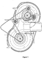
- Typically, center rear discharge ("CRD") decks use two to three blades to cut grass and propel grass clippings out the center/rear of the deck. The grass clippings are propelled to the center/rear of the deck by having the left most (with respect to operator seating position) blade rotate clockwise and the right most blade rotating counter clockwise. The counter rotating blades, along with housing shape, push air and grass clippings towards the center rear of the deck. Generally, the blades are driven by a belt with a clockwise rotating engine. The left blade is usually driven with the inside of the belt causing it to rotate in a first direction. The right hand blade is usually driven by the outside of the belt causing it to rotate in a second direction. In order to drive the right hand blade with the outside of the belt, a double-sided belt and several idler pulleys are typically utilized. It is also common practice to tension the belt system using an idler arm on the right side. This deck pulley system tends to utilize an electric or mechanical clutching system at the engine to drive the belt. As such, typical CRD decks employ complicated belt drive, directional, and tensioning arrangements, such as those shown in
Figure 1 . These complicated systems require expensive belts, electro-mechanical clutching systems, and various other components which increase the cost and maintenance, and reduce the reliability of typical CRD decks. - In accordance with a first aspect of the invention there is provided a center rear discharge deck system in accordance with claim 1.
- Preferably and/or optional features of the first aspect of the invention may be found in claims 2 to 6.
- In accordance with a second aspect of the invention there is provided a lawnmower in accordance with claim 7.
- Preferable and/or optional features of the second aspect of the invention may be found in claim 8 and claim 9.
- In accordance with a third aspect of the invention there is provided a method for operating a lawnmower in accordance with claim 10.
- Preferable and/or optional features of the third aspect of the invention may be found in claim 11 and claim 12.
- In an exemplary embodiment, a center rear discharge deck system comprises a belt, a first cutter, a gearbox and a second cutter. The belt comprises a first side and a second side. The second side may be configured with a plurality of grooves or teeth to engage the first cutter and the second cutter. The first cutter may comprise one blade. The second cutter may comprise one blade or two blades. The gear box may further comprise a rotatable belt engagement. The rotatable belt engagement may be configured to operate as a clutching mechanism and/or a belt tensioning system. Where the rotatable belt engagement is configured as a clutching system, the first cutter and the second cutter may be engaged and disengaged, based on user input. The center rear discharge deck may further comprise a housing and a discharge. The housing may be configured to at least partially enclose the first cutter and the second cutter, such that clippings produced by the first cutter and the second cutter are retained and conducted to the discharge.
- The riding lawnmower may comprise a center rear discharge deck, a frame and a motor. The center rear discharge deck may comprise a belt, a second cutter and a second engagement. The second cutter may be rotatable in a second direction of rotation in response to movement from the belt. The second engagement may be coupled to the second cutter, such that the second engagement is configured to engage the belt at a first position and disengage the belt at a second position. The center rear discharge deck may be coupled to the frame. The motor may also be coupled to the frame and may be configured to provide power and a first movement in a first direction of rotation to the belt.
- The lawnmower may further comprise a gear box operatively coupled to the second engagement. The gear box may comprise an engagement gear configured to move in the first direction of rotation and a drive gear configured to move in the second direction of rotation, in response to a movement of the engagement gear.
- The second engagement of the lawnmower may be configured as a belt tensioning system and/or a clutching system, such that the first cutter and second cutter can be engaged and disengaged in response to a user input.
- An exemplary method for operating a lawnmower may comprise tensioning a belt to a power transfer mechanism of a motor and a second engagement, in response to a user input. The method also includes rotating the second engagement by the belt in a first direction of rotation, wherein the second engagement is coupled to a gear box comprising an engagement gear operatively engaged with a drive gear, and wherein the engagement gear is configured to rotate in the first direction of rotation and the drive gear is configured to rotate in a second direction of rotation. The method further includes rotating a second cutter by the drive gear in the second direction of rotation, wherein the second cutter is at least partially enclosed by a housing. The method further includes rotating a first cutter by the belt at a first engagement in the first direction of rotation, wherein the first cutter is at least partially enclosed by the housing. The method further includes conducting clippings from the first cutter and the second cutter through the housing to a center rear discharge.
- A more complete understanding may be derived by referring to the detailed description and claims when considered in connection with the Figures, wherein like reference numbers refer to similar elements throughout the Figures, and:
-
FIGURE 1 illustrates a prior art center rear discharge deck; -
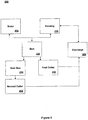
FIGURE 2 illustrates a block diagram of components of an exemplary center rear discharge deck, in accordance with an exemplary embodiment; -
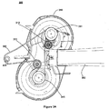
FIGURE 3A illustrates a top view of an exemplary center rear discharge deck, in accordance with an exemplary embodiment; -
FIGURE 3B illustrates a perspective view of an exemplary center rear discharge deck, in accordance with an exemplary embodiment; -
FIGURE 3C illustrates a top view of an exemplary gearbox and belt engagement mechanism of center rear discharge deck, in accordance with an exemplary embodiment; -
FIGURE 3D illustrates a bottom view of an exemplary center rear discharge deck, in accordance with an exemplary embodiment; and -
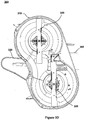
FIGURE 4 illustrates an exemplary center rear discharge deck couple to a riding lawn mower, in accordance with an exemplary embodiment. - The following description is of various exemplary embodiments only, and is not intended to limit the scope, applicability or configuration of the present disclosure in any way. Rather, the following description is intended to provide a convenient illustration for implementing various embodiments including the best mode. As will become apparent, various changes may be made in the function and arrangement of the elements described in these embodiments, without departing from the scope of the appended claims. For example, the steps recited in any of the method or process descriptions may be executed in any order and are not necessarily limited to the order presented. Moreover, many of the manufacturing functions or steps may be outsourced to or performed by one or more third parties. Furthermore, any reference to singular includes plural embodiments, and any reference to more than one component or step may include a singular embodiment or step. Also, any reference to attached, fixed, connected or the like may include permanent, removable, temporary, partial, full and/or any other possible attachment option. As used herein, the terms "coupled", "coupling," or any other variation thereof, are intended to cover a physical connection, an electrical connection, a magnetic connection, an optical connection, a communicative connection, a functional connection, and/or any other connection.
- For the sake of brevity, conventional techniques for mechanical system construction, management, operation, measurement, optimization, and/or control, as well as conventional techniques for mechanical power transfer, modulation, control, and/or use, may not be described in detail herein. Furthermore, the connecting lines shown in various figures contained herein are intended to represent exemplary functional relationships and/or physical couplings between various elements. It should be noted that many alternative or additional functional relationships or physical connections may be present in a CRD deck.
- Principles of the present disclosure reduce and/or eliminate problems with prior center/rear discharge decks for riding lawnmowers. For example, by eliminating the need for complicated pulley arrangements, and electro-mechanical clutching systems, a CRD deck may be produced in a more cost effective manner. The reliability of a CRD deck is improved by reducing the number of mechanical and/or electro-mechanical components. Similarly, the maintenance of a CRD deck is reduced by reducing the number of mechanical and/or electro-mechanical components.
- In various exemplary embodiments, with reference to
Figure 2 , aCRD deck 200 may be any mechanical or electro-mechanical system configured to cut vegetation or other items.CRD deck 200 may comprise ahousing 210, abelt 220, agearbox 230, afirst cutter 240, asecond cutter 250, and/or adischarge 260.CRD deck 200 may also be configured to interface with amotor 205. -
CRD deck 200 may be configured to transfer power frommotor 205 atbelt 220 tofirst cutter 240.Belt 220 may also be configured to transfer power togearbox 230, which in turn provides power tosecond cutter 250. Moreover,belt 220 may be configured to provide power tofirst cutter 240 andsecond cutter 250, such that the cutters rotate in opposing directions. -
First cutter 240 andsecond cutter 250 may be operatively coupled withinhousing 210.First cutter 240 andsecond cutter 250 may also be configured to conduct clippings (e.g. grass clippings, and/or vegetation clippings) within the volume ofhousing 210 to discharge 260.Discharge 260 may be configured to exhaust the clippings fromhousing 210 into a mowed area or into a suitable clipping capture mechanism (e.g. a grass catcher). - In an exemplary embodiment, and with reference to
Figure 3A ,Figure 3B , andFigure 3C , aCRD deck 300 may be any suitable mechanical and/or electro-mechanical structure configured to cut vegetation when used with a riding lawnmower.CRD 300 may be configured to receive power from a motor configured with a motorpower output mechanism 305. Further,CRD deck 300 may comprise ahousing 310, abelt 320, agearbox 330, afirst belt engagement 341, and asecond belt engagement 351.Gearbox 330 may be coupled tohousing 310.First belt engagement 341 may also be coupledhousing 310.Second belt engagement 351 may be configured to engagegearbox 330 and may be coupled tohousing 310.Belt 320 may be configured to couple with motorpower output mechanism 305 and conduct power from a generator to the various components ofCRD deck 300. For example,belt 320 may be configured to engagefirst belt engagement 341 andsecond belt engagement 351, such that the power and corresponding movement provided from motorpower output mechanism 305 to belt 320 causes movement ofsecond belt engagement 351 and movement ofgearbox 330. - Motor
power output mechanism 305 any suitable transfer mechanism coupled to any suitable generator configured to provide output power. Motorpower output mechanism 305 may include, for example, a shaft, a gear, a fly wheel, and/or the like. The generator may be an internal combustion engine, an electric motor, or any other suitable power generator. -
Housing 310 may be any suitable structure configured to contain and conduct a substantial portion of grass clippings to a discharge.Housing 310 may define a volume. The volume may be any suitable shape for retaining and conducting a substantial portion of clippings.Housing 310 may be made of metal, plastic, composite, or any other suitable material that is durable enough for use in lawn maintenance equipment. -
Housing 310 may be monolithic.Housing 310 may comprise multiple components coupled together. Moreover,housing 310 may be cast, pressed, sintered, die-cut, machined, stamped, bonded, laminated, polished, smoothed, bent, rolled, molded, plated, coated, and/or otherwise shaped and/or formed via any suitable method and/or apparatus. -
Belt 320 may be any mechanism suitably configured to conduct power.Belt 320 comprises a first side and a second side. The first side may be substantially smooth such that it freely passes over a transfer mechanism, such as for example a pulley. The second side may comprise a friction mechanism or a friction surface (e.g. grooves, teeth and/or the like).Belt 320 may be operatively coupled to motorpower output mechanism 305 at, for example, a shaft, fly wheel, or other suitable engagement point. Further,belt 320 may operatively couple to engagement mechanisms operatively coupled tofirst cutter 340 andgearbox 330. - In an exemplary embodiment, and with reference to
Figure 3A andFigure 3C ,gearbox 330 may be any suitable power transfer mechanism.Gearbox 330 may be configured as a system of two or more gears, a worm drive, and/or any other suitable power transfer mechanism.Gearbox 330 may comprise anengagement gear 331 and adrive gear 332.Engagement gear 331 may be operatively coupled tosecond engagement 351.Engagement gear 331 may be configured to rotatable couple to or otherwise engagedrive gear 332. This configuration causessecond engagement 351 andengagement gear 331 to rotate in the same direction as the power transfer mechanism of motorpower output mechanism 305. As such, the configuration and coupling ofengagement gear 331 and drivegear 332 causes the gears to rotate in opposing directions, such thatdrive gear 332 rotates in the opposite direction of the power transfer mechanism of motorpower output mechanism 305. Moreover,drive gear 332 may couple to and drive a shaft. The shaft may be couple tosecond cutter 350. In an exemplary embodiment,second engagement 351 may be configured to transfer power and a resulting torque frombelt 320 toengagement gear 331. In turn,engagement gear 331 causes drivegear 332 to rotate. - In an embodiment,
first engagement 341,second engagement 351,engagement gear 331, and drivegear 332 may each be any suitable size.First engagement 341,second engagement 351,engagement gear 331, and drivegear 332 may be proportionally sized to achieve a desired rotational relationship betweenfirst cutter 340 andsecond cutter 350. For example,first engagement 341,second engagement 351,engagement gear 331,drive gear 332 may be sized such thatfirst cutter 340 andsecond cutter 350 rotate at substantially the same rotational speed (e.g. substantially the same rpm). -
Second engagement 351 andgearbox 330 may be configured as a belt tensioning system. As discussed above,drive gear 332 may be coupled to and drive a shaft. The shaft may be coupled tosecond cutter 350 and causessecond cutter 350 to rotate whenbelt 320 engagessecond engagement 351.Second engagement 351 may also be configured to rotate about or with respect to the shaft such thatbelt 320 is loosened or tightened depending on a user selected operating condition. For example,second engagement 351 may be coupled to abelt tensioning mechanism 321. -
Belt tensioning mechanism 321 may be any suitable mechanism or assembly configured to accept a user input and cause the position of at least onefirst engagement 341 andsecond engagement 351 to change position in response to the user input. For example, belt tensioning mechanism may include various linkage assemblies, cables, springs, fasteners, force transfer mechanisms, assemblies, and the like. - Where
belt 320 is loosened based on a user input at thebelt tensioning mechanism 321,belt 320 blossoms (e.g. loosens such thatbelt 320 does not engage and/or rotate thefirst engagement 341 and/or second engagement 351) and the motor is able to run and otherwise drive the riding lawnmower withoutfirst cutter 340 orsecond cutter 350 rotating. Where the user desires to employfirst cutter 340 andsecond cutter 350, the user may provide an input to the belt tensioning mechanism, which causesbelt 320 to rotate, such thatbelt 320 tightens aboutsecond engagement 351. The rotation and resulting tighteningcause belt 320 to engage and drivefirst engagement 340 andsecond engagement 351, which in turn drivesfirst cutter 340 orsecond cutter 350. - The configuration and rotation of
second engagement 351 also acts as a clutching system. As discussed above, this clutching system allows the user to select whether to operatefirst cutter 340 andsecond cutter 350, while still being able to drive a riding lawn mower under the power of the motor. - This configuration also reduces the need for expensive components and a complicated electromechanical system, including for example, idler pulleys, and a motor clutching system. In particular, the configuration of
engagement gear 331 and drivegear 332 provide a rotational movement tosecond cutter 350 in the opposite direction as the rotation of motorpower output mechanism 305. The idler puller (as shown inFigure 1 ) is no longer needed because appropriate tension may be applied tobelt 320 usingsecond engagement 351. The motor clutching system (which is typically employed with a system like that shown inFigure 1 ) is also no longer needed because of the rotating functionality ofsecond engagement 351, which allows the user to engage and disengagefirst cutter 340 andsecond cutter 350. -
CRD 300 may further comprise one of more pulleys, including forexample pulley 311 and/orpulley 312.Pulley 311 and/orpulley 312 may be coupled tohousing 310. Moreover,pulley 311 and/orpulley 312 may be configured to freely rotate, while maintaining their respective position onhousing 310.Pulley 311 may be configured to slidably engage anddirect belt 320. Similarly,pulley 312 may be configured to slidably engage anddirect belt 320.Pulley 311 and/orpulley 312 may be configured to engage the first side ofbelt 320. As such,pulley 311 and/orpulley 312 are configured to allowbelt 320 to freely pass overpulley 311 and/orpulley 312 with minimal friction. - In an embodiment,
pulley 311 and/orpulley 312 may each be any suitable size.Pulley 311 and/orpulley 312 may be proportionally sized to achieve a desired rotational relationship betweenfirst cutter 340 andsecond cutter 350. For example,pulley 311 and/orpulley 312 may be sized such thatfirst cutter 340 andsecond cutter 350 rotate at substantially the same rotational speed (e.g. substantially the same rpm). - In an exemplary embodiment and with reference to
Figure 3C andFigure 3D ,CRD deck 300 may further comprise afirst cutter 340 and asecond cutter 350.First cutter 340 may couple tofirst engagement 341. As such, first cutter may be rotated to belt 320 in the same direction as motorpower output mechanism 305.Second cutter 350 may couple to drivegear 332. As such,second cutter 350 rotates in the opposite direction of the motion of bothfirst cutter 340 and motorpower output mechanism 305. - In an embodiment, the respective swept circles of
first cutter 340 andsecond cutter 350 may not overlap (e.g. the distance between centers offirst cutter 340 andsecond cutter 350 are more than twice the blade radius).First cutter 340 andsecond cutter 350 the cutters may be transversely offset by, for example, approximately 10 degrees to 30 degrees so that no track of uncut grass is left betweenfirst cutter 340 andsecond cutter 350. -
First cutter 340 may be any structure or mechanism configured to cut vegetation or other items.First cutter 340 may comprise at least one blade. In various embodiments,first cutter 340 may comprise more than one blade. In various embodiments,first cutter 340 may comprise more than one blade.First cutter 340 may also be coupled to a shaft, such thatfirst cutter 340 is able to rotate. In an embodiment, afirst cutter 340 is driven bybelt 320 at a belt engagement mechanism, wherein the second side of the belt drives the engagement mechanism. The belt engagement mechanism may couple directly to the shaft, and as suchfirst cutter 340 may be rotated in the same direction as the drive mechanism. - Like
first cutter 340,second cutter 350 may be any structure or mechanism configured to cut vegetation.Second cutter 350 may comprise at least one blade. In various embodiments,second cutter 350 may comprise more than one blade.Second cutter 350 may also be coupled to a shaft, such thatsecond cutter 350 is able to rotate. In an embodiment, asecond cutter 350 is driven bybelt 320 at a belt engagement mechanism throughgearbox 330, wherein the second side of the belt drives the engagement mechanism. The belt engagement mechanism may couple to a first gear in the gearbox which rotates in the same direction as the drive mechanism. The first gear may interface with a second gear. The second gear may be coupled to the shaft which supportssecond cutter 350. Further, the first gear may drive the second gear, causing the second gear to rotate in a direction that is opposite of the rotation of the drive mechanism. As such,second cutter 350 may be rotated in a direction that is opposite of the rotation of the drive mechanism. -
First cutter 340 may have a substantially rectangular shape, having two long sides and two shorter ends. Additionally,first cutter 340 may include various balancing and/or tuning mechanisms and/or structures, including for example, tabs at each end offirst cutter 340.First cutter 340 may be configured with at least one substantially tapered (e.g. substantially sharp) edge along the leading long side (e.g. the long side which engages vegetation based on the direction of rotation of first cutter 340). In various embodiments,first cutter 340 may be configured with a substantially tapered (e.g. substantially sharp) edge along each long side, which allowsfirst cutter 340 to more effectively cut various thickness or vegetation and produce a smaller (e.g. more finely chopped) clipping. Moreover,first cutter 340 may be configured with one or more blades as described above. - Similar to
first cutter 340,second cutter 350 may have a substantially rectangular shape, having two long sides and two shorter ends. Additionally,second cutter 350 may include various balancing and/or tuning mechanisms and/or structures, including for example, tabs at each end ofsecond cutter 350.Second cutter 350 may be configured with at least one substantially tapered (e.g. substantially sharp) edge along the leading long side (e.g. the long side which engages vegetation based on the direction of rotation of second cutter 350).Second cutter 350 may be configured with substantially tapered (e.g. substantially sharp) edge along each long side, which allowssecond cutter 350 to more effectively cut various thickness or vegetation and produce a smaller (e.g. more finely chopped) clipping. Moreover,second cutter 350 may be configured with one or more blades as described above. - In an exemplary embodiment, and with continued reference to
Figure 3A andFigure 3D ,discharge 360 may be any structure suitable for conducting clippings fromhousing 310.Discharge 360 may be coupled tohousing 310. For example, discharge 360 may be a chute, conduit, tube, or any other suitable structure.Discharge 360 may couple at or near the center ofhousing 310 betweenfirst cutter 340 andsecond cutter 350. As such,discharge 360 may be configured to exhaust clippings from the back of a riding lawn mower (e.g. away from the direction of travel of the mower). - In an exemplary embodiment, and with reference to
Figure 4 , theCRD deck 400 may be provided as a component of a mowing system.CRD deck 400 may be coupled to or installed on ariding lawnmower 460. Ridinglawnmower 460 may be any suitable lawnmower or lawn-tractor suitably configured to accept a rear discharge deck. Ridinglawnmower 460 may be configured to accept and obtain power from motor 405. Moreover, the riding lawnmower may comprise aframe 461, abody 462,wheels 463, asteering system 464 and various other components, including for example, gauges, lights, a fuel tank, a starting system, and/or the like. - Riding
lawnmower 460 may be configured with any type ofsteering system 464, including for example, zero-turn steering, a standard steering configuration, or any other suitable configuration now known or hereinafter devised. Moreover, ridinglawnmower 460 may employ any accessory available or otherwise configured to interface withCRD deck 400 including for example, a vacuum system, a bagging system, a blower system, or any other system now known or hereinafter devised. - While the principles of this disclosure have been shown in various embodiments, many modifications of structure, arrangements, proportions, elements, materials and components (which are particularly adapted for a specific environment and operating requirements) may be used without departing from the principles and scope of this disclosure. These and other changes or modifications are intended to be included within the scope of the present disclosure and may be expressed in the following claims.
- The present disclosure has been described with reference to various embodiments. However, one of ordinary skill in the art appreciates that various modifications and changes can be made without departing from the scope of the present disclosure. Accordingly, the specification is to be regarded in an illustrative rather than a restrictive sense, and all such modifications are intended to be included within the scope of the present disclosure. Likewise, benefits, other advantages, and solutions to problems have been described above with regard to various embodiments. However, benefits, advantages, solutions to problems, and any element(s) that may cause any benefit, advantage, or solution to occur or become more pronounced are not to be construed as a critical, required, or essential feature or element of any or all the claims. As used herein, the terms "comprises," "comprising," or any other variation thereof, are intended to cover a non-exclusive inclusion, such that a process, method, article, or apparatus that comprises a list of elements does not include only those elements but may include other elements not expressly listed or inherent to such process, method, article, or apparatus. When language similar to "at least one of A, B, or C" or "at least one of A, B, and C" is used in the claims or specification, the phrase is intended to mean any of the following: (1) at least one of A; (2) at least one of B; (3) at least one of C; (4) at least one of A and at least one of B; (5) at least one of B and at least one of C; (6) at least one of A and at least one of C; or (7) at least one of A, at least one of B, and at least one of C.
Claims (12)
- A center rear discharge deck system (300), comprising:a belt (320) comprising a first side and a second side;a first cutter (340) operatively engaged by the second side of the belt (320);a gearbox (330) comprising a drive gear (332) and an engagement gear (331) operatively engaged with the drive gear (332), wherein the engagement gear (331) is configured to rotate in a first direction of rotation and the drive gear (332) is configured to rotate in a second direction of rotation, and wherein the first and second directions of rotations being opposing directions of rotation;a second cutter (350) coupled to the drive gear (332) so that the first cutter (340) and the second cutter (350) rotate in opposing directions in response to movement from the belt (320);an engagement (351) coupled to the engagement gear (331) so that the engagement (351) is configured to be rotated by the belt (320) in the first direction of rotation;characterised by the gearbox (330) being operatively engaged by the second side of the belt (320) and wherein the engagement (351) and engagement gear (331) are configured to be moved from a first position that engages the belt (320) to a second position that disengages the belt (320).
- The system of claim 1, further comprising a belt tensioning device (321) to move the engagement (351) from the first position to the second position.
- The system of any preceding claim, wherein the engagement (351) comprises a pulley (312) connected with the engagement gear (331), and wherein the pulley (312) is coupled with the belt (320) to rotate the engagement gear (331) when the engagement (351) is in the first position.
- The system of any preceding claim, wherein the second cutter (350) is coupled to a shaft and the shaft is also coupled to the drive gear (332) so that when the drive gear (332) rotates, the second cutter (350) also rotates.
- The system of any preceding claim, wherein the engagement (351) is coupled to the engagement gear (331) along a common shaft such that the engagement gear (331) and the engagement (351) rotate in the same direction.
- The system of any preceding claim, wherein the rotatable belt engagement (351) is configured as a clutching system such that the first cutter (340) and the second cutter (350) may be engaged and disengaged based on user input.
- A lawnmower (460), comprising:a center rear discharge deck (300) comprising:a belt (320),a second cutter (350) movable in response to movement from the belt (320);an engagement gear (331) configured to rotate in a first direction of rotation;a drive gear (332) operatively engaged with the engagement gear (331) and the second cutter (350);an engagement (351) coupled to the engagement gear (331) and rotatably coupled to the second cutter (350);a frame (461) wherein the center rear discharge deck (300) is coupled to the frame (461); anda motor (405) coupled to the frame, wherein the motor (405) is configured to provide power and a first movement in a first direction of rotation to the belt (320);characterised in that the engagement (351) is configured to engage the belt in a first position and disengage the belt (320) in a second position by rotating about the drive gear (332).
- The lawnmower of claim 7,
wherein the engagement (351) and engagement gear (331) are attached to a first common shaft and rotate in a first direction of rotation,
wherein the second cutter (350) and the drive gear (332) are attached to a second common shaft,
wherein the drive gear (332) is coupled to the engagement gear (331) to rotate both the drive gear (332) and second cutter (350) in a second direction of rotation, and
wherein the first and second directions of rotation are substantially opposite. - The lawnmower of claim 8, further comprising a first cutter (340) movable in the first direction of rotation in response to movement from the belt (320), wherein the belt (320) comprises a first side and a second side, and wherein the first side comprises a substantially smooth surface, and wherein the second side comprises a plurality of grooves or a plurality of teeth.
- A method for operating a lawnmower comprising:tensioning a belt (320) to a power transfer mechanism of a motor (405) and a second engagement (351) in response to user input, wherein the second engagement (351) is coupled to an engagement gear (331) via a shaft, and wherein the engagement gear (331) is operatively engaged with a drive gear (332);rotating the second engagement (351) by the belt (320) in a first direction of rotation, thereby rotating the engagement gear (331) in the first direction of rotation and rotating the drive gear (332) in a second direction of rotation;rotating a second cutter (350) by the drive gear (332) in the second direction of rotation, wherein the second cutter (350) is at least partially enclosed by a housing (310); androtating a first cutter (340) by the belt (320) at a first engagement (341) in the first direction of rotation, wherein the first cutter (340) is at least partially enclosed by the housing (310),wherein the second engagement (351) is configured to be moved from a first position to
a second position, wherein the first position corresponds to engaging the belt (320) with the second engagement (351), and wherein the second position corresponds to disengaging the belt (320) with the second engagement (351). - The method of claim 10, wherein the second engagement (351) and engagement gear (331) are attached to a first common shaft and rotate in a first direction of rotation, wherein the second cutter (350) and the drive gear (332) are attached to a second common shaft, wherein the drive gear (332) is coupled to the engagement gear (331) to rotate both the drive gear (332) and second cutter (350) in a second direction of rotation.
- The method of claim 10 or 11, further comprising conducting clippings from the first cutter (340) and the second cutter (350) through the housing (310) to a center rear discharge, and wherein the first direction of rotation is substantially opposite to the second direction of rotation.
Applications Claiming Priority (1)
| Application Number | Priority Date | Filing Date | Title |
|---|---|---|---|
| PCT/US2010/047235 WO2012030325A1 (en) | 2010-08-31 | 2010-08-31 | Center rear discharge deck |
Publications (3)
| Publication Number | Publication Date |
|---|---|
| EP2611277A1 EP2611277A1 (en) | 2013-07-10 |
| EP2611277A4 EP2611277A4 (en) | 2015-09-09 |
| EP2611277B1 true EP2611277B1 (en) | 2018-03-21 |
Family
ID=45773166
Family Applications (1)
| Application Number | Title | Priority Date | Filing Date |
|---|---|---|---|
| EP10856798.3A Active EP2611277B1 (en) | 2010-08-31 | 2010-08-31 | Center rear discharge deck |
Country Status (6)
| Country | Link |
|---|---|
| US (1) | US8635841B2 (en) |
| EP (1) | EP2611277B1 (en) |
| CN (1) | CN103188928B (en) |
| AU (1) | AU2010359872B2 (en) |
| CA (1) | CA2809235C (en) |
| WO (1) | WO2012030325A1 (en) |
Families Citing this family (16)
| Publication number | Priority date | Publication date | Assignee | Title |
|---|---|---|---|---|
| EP2013671B1 (en) | 2006-03-17 | 2018-04-25 | iRobot Corporation | Lawn care robot |
| JP2014060940A (en) * | 2012-09-20 | 2014-04-10 | Honda Motor Co Ltd | Riding-type lawn mower |
| EP3889717A1 (en) | 2014-03-31 | 2021-10-06 | iRobot Corporation | Autonomous mobile robot |
| US9516806B2 (en) | 2014-10-10 | 2016-12-13 | Irobot Corporation | Robotic lawn mowing boundary determination |
| US9510505B2 (en) | 2014-10-10 | 2016-12-06 | Irobot Corporation | Autonomous robot localization |
| US9420741B2 (en) | 2014-12-15 | 2016-08-23 | Irobot Corporation | Robot lawnmower mapping |
| US9538702B2 (en) | 2014-12-22 | 2017-01-10 | Irobot Corporation | Robotic mowing of separated lawn areas |
| JP6386388B2 (en) * | 2015-01-30 | 2018-09-05 | 株式会社クボタ | Mower |
| US11115798B2 (en) | 2015-07-23 | 2021-09-07 | Irobot Corporation | Pairing a beacon with a mobile robot |
| US10034421B2 (en) | 2015-07-24 | 2018-07-31 | Irobot Corporation | Controlling robotic lawnmowers |
| US10021830B2 (en) | 2016-02-02 | 2018-07-17 | Irobot Corporation | Blade assembly for a grass cutting mobile robot |
| US10459063B2 (en) | 2016-02-16 | 2019-10-29 | Irobot Corporation | Ranging and angle of arrival antenna system for a mobile robot |
| JP2017163871A (en) * | 2016-03-15 | 2017-09-21 | 本田技研工業株式会社 | Lawn mower |
| JP2017163872A (en) * | 2016-03-15 | 2017-09-21 | 本田技研工業株式会社 | Lawn mower |
| US11470774B2 (en) | 2017-07-14 | 2022-10-18 | Irobot Corporation | Blade assembly for a grass cutting mobile robot |
| JP7193415B2 (en) | 2019-05-21 | 2022-12-20 | 株式会社クボタ | mower unit |
Family Cites Families (7)
| Publication number | Priority date | Publication date | Assignee | Title |
|---|---|---|---|---|
| FR1500062A (en) * | 1966-06-21 | 1967-11-03 | Heywang Ets | Rotary mower |
| JP3025618B2 (en) | 1993-11-19 | 2000-03-27 | ユニッタ株式会社 | Power transmission belt, and cord and canvas used for the power transmission belt |
| US5669213A (en) * | 1995-11-03 | 1997-09-23 | Allied Products Corporation | Counterrotation mulching mower |
| JPH09187140A (en) * | 1996-01-05 | 1997-07-22 | Honda Motor Co Ltd | Apparatus for driving cutter blade of lawn mower |
| US6176071B1 (en) * | 1999-09-10 | 2001-01-23 | Deere & Company | Tensioning idler assembly for mower deck belt drive |
| JP4096701B2 (en) * | 2002-11-06 | 2008-06-04 | 井関農機株式会社 | Mowing equipment |
| CN201243488Y (en) * | 2008-05-23 | 2009-05-27 | 无锡职业技术学院 | Multifunctional remote control lawn trimmer |
-
2010
- 2010-08-31 CN CN201080069921.3A patent/CN103188928B/en not_active Expired - Fee Related
- 2010-08-31 US US13/819,780 patent/US8635841B2/en active Active
- 2010-08-31 WO PCT/US2010/047235 patent/WO2012030325A1/en active Application Filing
- 2010-08-31 EP EP10856798.3A patent/EP2611277B1/en active Active
- 2010-08-31 CA CA2809235A patent/CA2809235C/en not_active Expired - Fee Related
- 2010-08-31 AU AU2010359872A patent/AU2010359872B2/en active Active
Non-Patent Citations (1)
| Title |
|---|
| None * |
Also Published As
| Publication number | Publication date |
|---|---|
| EP2611277A1 (en) | 2013-07-10 |
| CN103188928B (en) | 2017-05-10 |
| AU2010359872B2 (en) | 2014-12-18 |
| US20130152538A1 (en) | 2013-06-20 |
| AU2010359872A1 (en) | 2013-03-14 |
| CA2809235A1 (en) | 2012-03-08 |
| CN103188928A (en) | 2013-07-03 |
| EP2611277A4 (en) | 2015-09-09 |
| US8635841B2 (en) | 2014-01-28 |
| CA2809235C (en) | 2017-10-24 |
| WO2012030325A1 (en) | 2012-03-08 |
Similar Documents
| Publication | Publication Date | Title |
|---|---|---|
| EP2611277B1 (en) | Center rear discharge deck | |
| US6604348B2 (en) | Mower with engine-driven blade and electrical propulsion | |
| US11102925B2 (en) | All wheel drive, walk behind mower | |
| US6948299B2 (en) | Hybrid power equipment | |
| US10897845B2 (en) | Cutter housing assembly for a lawnmower, lawnmower having same, and convertible lawnmower | |
| US9032701B2 (en) | Grass collection system with through-shaft PTO | |
| US11006573B2 (en) | Cutter housing assembly for a lawnmower, lawnmower having same, and convertible lawnmower | |
| EP1597956A1 (en) | Walk behind mower with clutch | |
| EP2966969B1 (en) | Drive system for walk behind mower | |
| EP1457103B1 (en) | Throttle | |
| JP2003158907A (en) | Sulky lawn mower | |
| EP3370501B1 (en) | Disengagement mechanism for a walk behind mower | |
| KR20170054067A (en) | sub mower for boarding type mower | |
| JPH04299910A (en) | Mowing machine |
Legal Events
| Date | Code | Title | Description |
|---|---|---|---|
| PUAI | Public reference made under article 153(3) epc to a published international application that has entered the european phase |
Free format text: ORIGINAL CODE: 0009012 |
|
| 17P | Request for examination filed |
Effective date: 20130315 |
|
| AK | Designated contracting states |
Kind code of ref document: A1 Designated state(s): AL AT BE BG CH CY CZ DE DK EE ES FI FR GB GR HR HU IE IS IT LI LT LU LV MC MK MT NL NO PL PT RO SE SI SK SM TR |
|
| DAX | Request for extension of the european patent (deleted) | ||
| RAP1 | Party data changed (applicant data changed or rights of an application transferred) |
Owner name: HUSQVARNA AB |
|
| REG | Reference to a national code |
Ref country code: DE Ref legal event code: R079 Ref document number: 602010049417 Country of ref document: DE Free format text: PREVIOUS MAIN CLASS: A01D0034840000 Ipc: A01D0034710000 |
|
| RA4 | Supplementary search report drawn up and despatched (corrected) |
Effective date: 20150807 |
|
| RIC1 | Information provided on ipc code assigned before grant |
Ipc: A01D 34/71 20060101AFI20150803BHEP Ipc: A01D 34/76 20060101ALI20150803BHEP |
|
| 17Q | First examination report despatched |
Effective date: 20170331 |
|
| GRAP | Despatch of communication of intention to grant a patent |
Free format text: ORIGINAL CODE: EPIDOSNIGR1 |
|
| INTG | Intention to grant announced |
Effective date: 20171004 |
|
| RIN1 | Information on inventor provided before grant (corrected) |
Inventor name: CHAPMAN, SETH Inventor name: FISER, JAKE |
|
| GRAJ | Information related to disapproval of communication of intention to grant by the applicant or resumption of examination proceedings by the epo deleted |
Free format text: ORIGINAL CODE: EPIDOSDIGR1 |
|
| GRAR | Information related to intention to grant a patent recorded |
Free format text: ORIGINAL CODE: EPIDOSNIGR71 |
|
| GRAS | Grant fee paid |
Free format text: ORIGINAL CODE: EPIDOSNIGR3 |
|
| GRAA | (expected) grant |
Free format text: ORIGINAL CODE: 0009210 |
|
| INTC | Intention to grant announced (deleted) | ||
| AK | Designated contracting states |
Kind code of ref document: B1 Designated state(s): AL AT BE BG CH CY CZ DE DK EE ES FI FR GB GR HR HU IE IS IT LI LT LU LV MC MK MT NL NO PL PT RO SE SI SK SM TR |
|
| INTG | Intention to grant announced |
Effective date: 20180212 |
|
| REG | Reference to a national code |
Ref country code: GB Ref legal event code: FG4D |
|
| REG | Reference to a national code |
Ref country code: CH Ref legal event code: EP |
|
| REG | Reference to a national code |
Ref country code: AT Ref legal event code: REF Ref document number: 980075 Country of ref document: AT Kind code of ref document: T Effective date: 20180415 |
|
| REG | Reference to a national code |
Ref country code: IE Ref legal event code: FG4D |
|
| REG | Reference to a national code |
Ref country code: DE Ref legal event code: R096 Ref document number: 602010049417 Country of ref document: DE |
|
| REG | Reference to a national code |
Ref country code: FR Ref legal event code: PLFP Year of fee payment: 9 |
|
| REG | Reference to a national code |
Ref country code: NL Ref legal event code: MP Effective date: 20180321 |
|
| PG25 | Lapsed in a contracting state [announced via postgrant information from national office to epo] |
Ref country code: NO Free format text: LAPSE BECAUSE OF FAILURE TO SUBMIT A TRANSLATION OF THE DESCRIPTION OR TO PAY THE FEE WITHIN THE PRESCRIBED TIME-LIMIT Effective date: 20180621 Ref country code: LT Free format text: LAPSE BECAUSE OF FAILURE TO SUBMIT A TRANSLATION OF THE DESCRIPTION OR TO PAY THE FEE WITHIN THE PRESCRIBED TIME-LIMIT Effective date: 20180321 Ref country code: HR Free format text: LAPSE BECAUSE OF FAILURE TO SUBMIT A TRANSLATION OF THE DESCRIPTION OR TO PAY THE FEE WITHIN THE PRESCRIBED TIME-LIMIT Effective date: 20180321 Ref country code: CY Free format text: LAPSE BECAUSE OF FAILURE TO SUBMIT A TRANSLATION OF THE DESCRIPTION OR TO PAY THE FEE WITHIN THE PRESCRIBED TIME-LIMIT Effective date: 20180321 Ref country code: FI Free format text: LAPSE BECAUSE OF FAILURE TO SUBMIT A TRANSLATION OF THE DESCRIPTION OR TO PAY THE FEE WITHIN THE PRESCRIBED TIME-LIMIT Effective date: 20180321 |
|
| REG | Reference to a national code |
Ref country code: LT Ref legal event code: MG4D |
|
| REG | Reference to a national code |
Ref country code: AT Ref legal event code: MK05 Ref document number: 980075 Country of ref document: AT Kind code of ref document: T Effective date: 20180321 |
|
| PG25 | Lapsed in a contracting state [announced via postgrant information from national office to epo] |
Ref country code: GR Free format text: LAPSE BECAUSE OF FAILURE TO SUBMIT A TRANSLATION OF THE DESCRIPTION OR TO PAY THE FEE WITHIN THE PRESCRIBED TIME-LIMIT Effective date: 20180622 Ref country code: LV Free format text: LAPSE BECAUSE OF FAILURE TO SUBMIT A TRANSLATION OF THE DESCRIPTION OR TO PAY THE FEE WITHIN THE PRESCRIBED TIME-LIMIT Effective date: 20180321 Ref country code: SE Free format text: LAPSE BECAUSE OF FAILURE TO SUBMIT A TRANSLATION OF THE DESCRIPTION OR TO PAY THE FEE WITHIN THE PRESCRIBED TIME-LIMIT Effective date: 20180321 Ref country code: BG Free format text: LAPSE BECAUSE OF FAILURE TO SUBMIT A TRANSLATION OF THE DESCRIPTION OR TO PAY THE FEE WITHIN THE PRESCRIBED TIME-LIMIT Effective date: 20180621 |
|
| PG25 | Lapsed in a contracting state [announced via postgrant information from national office to epo] |
Ref country code: PL Free format text: LAPSE BECAUSE OF FAILURE TO SUBMIT A TRANSLATION OF THE DESCRIPTION OR TO PAY THE FEE WITHIN THE PRESCRIBED TIME-LIMIT Effective date: 20180321 Ref country code: EE Free format text: LAPSE BECAUSE OF FAILURE TO SUBMIT A TRANSLATION OF THE DESCRIPTION OR TO PAY THE FEE WITHIN THE PRESCRIBED TIME-LIMIT Effective date: 20180321 Ref country code: AL Free format text: LAPSE BECAUSE OF FAILURE TO SUBMIT A TRANSLATION OF THE DESCRIPTION OR TO PAY THE FEE WITHIN THE PRESCRIBED TIME-LIMIT Effective date: 20180321 Ref country code: IT Free format text: LAPSE BECAUSE OF FAILURE TO SUBMIT A TRANSLATION OF THE DESCRIPTION OR TO PAY THE FEE WITHIN THE PRESCRIBED TIME-LIMIT Effective date: 20180321 Ref country code: ES Free format text: LAPSE BECAUSE OF FAILURE TO SUBMIT A TRANSLATION OF THE DESCRIPTION OR TO PAY THE FEE WITHIN THE PRESCRIBED TIME-LIMIT Effective date: 20180321 Ref country code: NL Free format text: LAPSE BECAUSE OF FAILURE TO SUBMIT A TRANSLATION OF THE DESCRIPTION OR TO PAY THE FEE WITHIN THE PRESCRIBED TIME-LIMIT Effective date: 20180321 Ref country code: RO Free format text: LAPSE BECAUSE OF FAILURE TO SUBMIT A TRANSLATION OF THE DESCRIPTION OR TO PAY THE FEE WITHIN THE PRESCRIBED TIME-LIMIT Effective date: 20180321 |
|
| PG25 | Lapsed in a contracting state [announced via postgrant information from national office to epo] |
Ref country code: CZ Free format text: LAPSE BECAUSE OF FAILURE TO SUBMIT A TRANSLATION OF THE DESCRIPTION OR TO PAY THE FEE WITHIN THE PRESCRIBED TIME-LIMIT Effective date: 20180321 Ref country code: SM Free format text: LAPSE BECAUSE OF FAILURE TO SUBMIT A TRANSLATION OF THE DESCRIPTION OR TO PAY THE FEE WITHIN THE PRESCRIBED TIME-LIMIT Effective date: 20180321 Ref country code: AT Free format text: LAPSE BECAUSE OF FAILURE TO SUBMIT A TRANSLATION OF THE DESCRIPTION OR TO PAY THE FEE WITHIN THE PRESCRIBED TIME-LIMIT Effective date: 20180321 Ref country code: SK Free format text: LAPSE BECAUSE OF FAILURE TO SUBMIT A TRANSLATION OF THE DESCRIPTION OR TO PAY THE FEE WITHIN THE PRESCRIBED TIME-LIMIT Effective date: 20180321 |
|
| PG25 | Lapsed in a contracting state [announced via postgrant information from national office to epo] |
Ref country code: PT Free format text: LAPSE BECAUSE OF FAILURE TO SUBMIT A TRANSLATION OF THE DESCRIPTION OR TO PAY THE FEE WITHIN THE PRESCRIBED TIME-LIMIT Effective date: 20180723 |
|
| REG | Reference to a national code |
Ref country code: DE Ref legal event code: R097 Ref document number: 602010049417 Country of ref document: DE |
|
| PLBE | No opposition filed within time limit |
Free format text: ORIGINAL CODE: 0009261 |
|
| STAA | Information on the status of an ep patent application or granted ep patent |
Free format text: STATUS: NO OPPOSITION FILED WITHIN TIME LIMIT |
|
| PG25 | Lapsed in a contracting state [announced via postgrant information from national office to epo] |
Ref country code: DK Free format text: LAPSE BECAUSE OF FAILURE TO SUBMIT A TRANSLATION OF THE DESCRIPTION OR TO PAY THE FEE WITHIN THE PRESCRIBED TIME-LIMIT Effective date: 20180321 |
|
| 26N | No opposition filed |
Effective date: 20190102 |
|
| PG25 | Lapsed in a contracting state [announced via postgrant information from national office to epo] |
Ref country code: MC Free format text: LAPSE BECAUSE OF FAILURE TO SUBMIT A TRANSLATION OF THE DESCRIPTION OR TO PAY THE FEE WITHIN THE PRESCRIBED TIME-LIMIT Effective date: 20180321 |
|
| REG | Reference to a national code |
Ref country code: CH Ref legal event code: PL |
|
| GBPC | Gb: european patent ceased through non-payment of renewal fee |
Effective date: 20180831 |
|
| PG25 | Lapsed in a contracting state [announced via postgrant information from national office to epo] |
Ref country code: LI Free format text: LAPSE BECAUSE OF NON-PAYMENT OF DUE FEES Effective date: 20180831 Ref country code: CH Free format text: LAPSE BECAUSE OF NON-PAYMENT OF DUE FEES Effective date: 20180831 Ref country code: LU Free format text: LAPSE BECAUSE OF NON-PAYMENT OF DUE FEES Effective date: 20180831 |
|
| REG | Reference to a national code |
Ref country code: BE Ref legal event code: MM Effective date: 20180831 |
|
| PG25 | Lapsed in a contracting state [announced via postgrant information from national office to epo] |
Ref country code: SI Free format text: LAPSE BECAUSE OF FAILURE TO SUBMIT A TRANSLATION OF THE DESCRIPTION OR TO PAY THE FEE WITHIN THE PRESCRIBED TIME-LIMIT Effective date: 20180321 |
|
| PG25 | Lapsed in a contracting state [announced via postgrant information from national office to epo] |
Ref country code: BE Free format text: LAPSE BECAUSE OF NON-PAYMENT OF DUE FEES Effective date: 20180831 |
|
| PG25 | Lapsed in a contracting state [announced via postgrant information from national office to epo] |
Ref country code: GB Free format text: LAPSE BECAUSE OF NON-PAYMENT OF DUE FEES Effective date: 20180831 |
|
| PG25 | Lapsed in a contracting state [announced via postgrant information from national office to epo] |
Ref country code: MT Free format text: LAPSE BECAUSE OF NON-PAYMENT OF DUE FEES Effective date: 20180831 |
|
| PG25 | Lapsed in a contracting state [announced via postgrant information from national office to epo] |
Ref country code: TR Free format text: LAPSE BECAUSE OF FAILURE TO SUBMIT A TRANSLATION OF THE DESCRIPTION OR TO PAY THE FEE WITHIN THE PRESCRIBED TIME-LIMIT Effective date: 20180321 |
|
| PG25 | Lapsed in a contracting state [announced via postgrant information from national office to epo] |
Ref country code: HU Free format text: LAPSE BECAUSE OF FAILURE TO SUBMIT A TRANSLATION OF THE DESCRIPTION OR TO PAY THE FEE WITHIN THE PRESCRIBED TIME-LIMIT; INVALID AB INITIO Effective date: 20100831 |
|
| PG25 | Lapsed in a contracting state [announced via postgrant information from national office to epo] |
Ref country code: IE Free format text: LAPSE BECAUSE OF NON-PAYMENT OF DUE FEES Effective date: 20180831 Ref country code: MK Free format text: LAPSE BECAUSE OF NON-PAYMENT OF DUE FEES Effective date: 20180321 |
|
| PG25 | Lapsed in a contracting state [announced via postgrant information from national office to epo] |
Ref country code: IS Free format text: LAPSE BECAUSE OF FAILURE TO SUBMIT A TRANSLATION OF THE DESCRIPTION OR TO PAY THE FEE WITHIN THE PRESCRIBED TIME-LIMIT Effective date: 20180721 |
|
| P01 | Opt-out of the competence of the unified patent court (upc) registered |
Effective date: 20230419 |
|
| PGFP | Annual fee paid to national office [announced via postgrant information from national office to epo] |
Ref country code: FR Payment date: 20230706 Year of fee payment: 14 Ref country code: DE Payment date: 20230705 Year of fee payment: 14 |