EP2610994A2 - Series-type charging device and charging method thereof - Google Patents
Series-type charging device and charging method thereof Download PDFInfo
- Publication number
- EP2610994A2 EP2610994A2 EP12162198.1A EP12162198A EP2610994A2 EP 2610994 A2 EP2610994 A2 EP 2610994A2 EP 12162198 A EP12162198 A EP 12162198A EP 2610994 A2 EP2610994 A2 EP 2610994A2
- Authority
- EP
- European Patent Office
- Prior art keywords
- power
- series
- upper limit
- limit value
- charging
- Prior art date
- Legal status (The legal status is an assumption and is not a legal conclusion. Google has not performed a legal analysis and makes no representation as to the accuracy of the status listed.)
- Granted
Links
Images


Classifications
-
- H—ELECTRICITY
- H02—GENERATION; CONVERSION OR DISTRIBUTION OF ELECTRIC POWER
- H02J—CIRCUIT ARRANGEMENTS OR SYSTEMS FOR SUPPLYING OR DISTRIBUTING ELECTRIC POWER; SYSTEMS FOR STORING ELECTRIC ENERGY
- H02J7/00—Circuit arrangements for charging or depolarising batteries or for supplying loads from batteries
-
- H—ELECTRICITY
- H02—GENERATION; CONVERSION OR DISTRIBUTION OF ELECTRIC POWER
- H02J—CIRCUIT ARRANGEMENTS OR SYSTEMS FOR SUPPLYING OR DISTRIBUTING ELECTRIC POWER; SYSTEMS FOR STORING ELECTRIC ENERGY
- H02J2207/00—Indexing scheme relating to details of circuit arrangements for charging or depolarising batteries or for supplying loads from batteries
- H02J2207/20—Charging or discharging characterised by the power electronics converter
-
- H—ELECTRICITY
- H02—GENERATION; CONVERSION OR DISTRIBUTION OF ELECTRIC POWER
- H02M—APPARATUS FOR CONVERSION BETWEEN AC AND AC, BETWEEN AC AND DC, OR BETWEEN DC AND DC, AND FOR USE WITH MAINS OR SIMILAR POWER SUPPLY SYSTEMS; CONVERSION OF DC OR AC INPUT POWER INTO SURGE OUTPUT POWER; CONTROL OR REGULATION THEREOF
- H02M3/00—Conversion of dc power input into dc power output
- H02M3/02—Conversion of dc power input into dc power output without intermediate conversion into ac
- H02M3/04—Conversion of dc power input into dc power output without intermediate conversion into ac by static converters
- H02M3/06—Conversion of dc power input into dc power output without intermediate conversion into ac by static converters using resistors or capacitors, e.g. potential divider
- H02M3/07—Conversion of dc power input into dc power output without intermediate conversion into ac by static converters using resistors or capacitors, e.g. potential divider using capacitors charged and discharged alternately by semiconductor devices with control electrode, e.g. charge pumps
- H02M3/072—Conversion of dc power input into dc power output without intermediate conversion into ac by static converters using resistors or capacitors, e.g. potential divider using capacitors charged and discharged alternately by semiconductor devices with control electrode, e.g. charge pumps adapted to generate an output voltage whose value is lower than the input voltage
Definitions
- the present invention relates to a series-type charging device and a charging method thereof, and more particularly to the device and method that use a control unit and a detector unit to adjust an input power, an output power and a next-level power to achieve the effect of completely utilizing the inputted power to charge a battery.
- a charger capable of charging a large quantity of power is developed in form of series-type expandable charger which combines a plurality of charging batteries for charging, but the chargers of this type charge one battery or a set of batteries, and then the next battery or group of batteries will be charged after the previous one or set are fully charged, so that the external inputted charging power is greater than the required charging power for charging the battery, and the remaining power cannot be used further to cause an unnecessary waste.
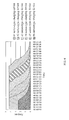
- an adapter capable of supplying a maximum current of 4.35 amperes is provided. Due to the properties of charging batteries, the charging current can only be increased to a maximum of 2.5 amperes, so that the remaining 1.85 amperes cannot be used at the beginning. In other words, the total power supply of the adapter cannot be utilized completely (which is indicated by the difference between the two color lines in the figure), and the whole charging process takes about 3 hours and 2 minutes. In the conventional charging method, it takes approximately 18 hours and 12 minutes to charge a group of six serial batteries.
- the inventor of the present invention designed a series-type charging device and a charging method thereof, wherein a charging control IC is integrated with a power detector to improve the problem of failing to fully utilize the total power, so as to achieve the effect of improving the charging efficiency.
- the present invention provides a series-type charging device, comprising: an input-terminal, an output-terminal, a control unit and a detector unit.
- the input-terminal receives an input power.
- the output-terminal connects the input-terminal and another series-type charging device and provides a next-level power.
- the control unit connects the input-terminal and the output-terminal and stores an upper limit value of the input power, and obtains an output power by a shunt of the input power.
- the control unit generates a charging power according to the output power, and charges a battery.
- the detector unit is connected between the input-terminal and the output-terminal to measure a supply power of the input power.
- the output-terminal connects the other series-type charging device
- the output power is reduced, and the input power is converted completely into the next-level power to charge the battery of another series-type charging device in a first priority
- the supply power of the series-type charging device has not reached the upper limit value
- the remaining input power is distributed immediately to the other series-type charging device to charge the battery of the series-type charging device.
- control unit further comprises a comparator and a modulator, and the modulator controls the control unit based on the comparator to generate the charging power.
- the input power of the input-terminal is supplied by a power supply device, and the upper limit value is equal to a rated power of the power supply device, and the modulator controls the control unit according to the upper limit value to maintain the input power below the upper limit value.
- the comparator stores an upper limit of a charging power according to a specification of the battery, and the modulator controls the control unit according to the upper limit value of the charging power to maintain the charging power below the upper limit of the charging power.
- the modulator when the comparator determines that the difference between the upper limit value and the supply power is greater than or equal to the charging power upper limit value, the modulator will control the control unit to generate the charge power equal to the upper limit value of the charging power.
- the modulator when the comparator determines that the difference between the upper limit value and the supply power is smaller than the upper limit value of the charging power and greater than zero, the modulator will control the control unit to generate the charging power same as the difference between the upper limit value and the supply power.
- the modulator when the comparator determines that the difference between the upper limit value and the supply power is equal to zero, the modulator will control the control unit not to generate the charging power.
- the present invention further provides a charging method of a series-type charging device, and the charging method comprises the steps of: receiving an input power by an input-terminal; connecting to another series-type charging device through an output-terminal to supply a next-level power; measuring a supply power of the input power by a detector unit; obtaining an output power by a current division of the input power, and using a charging control unit to generate a charging power according to the output power to charge a battery; determining whether to connect the output-terminal to another series-type charging device, reducing the output power when another device is connected and converting the input power completely into the next-level power to charge the battery of the other series-type charging device in a first priority; and determine whether the supply power of the series-type charging device has reached an upper limit, when the upper limit value has not been reached then distributing the remaining input power to the other series-type charging device immediately and charging the battery of the series-type charging device.
- control unit further comprises a comparator and a modulator, and the modulator controls the control unit to generate the charging power based on the comparator.
- the input power of the input-terminal is supplied by a power supply device, and the upper limit value is equal to a rated power of the power supply device and the modulator controls the control unit to maintain the input power below the upper limit value.
- the comparator stores an upper limit of a charging power according to a specification of the battery, and the modulator controls the control unit according to the upper limit value of the charging power to maintain the charging power below the upper limit of the charging power.
- the comparator is used to determine a difference between the upper limit value and the supply power and a relation with the upper limit value of the charging power, and the modulator controls the control unit to generate the charging power based on the comparator.
- the modulator when the comparator determines that the difference between the upper limit value and the supply power is greater than or equal to the charging power upper limit value, the modulator will control the control unit to generate the charge power equal to the upper limit value of the charging power.
- the modulator when the comparator determines that the difference between the upper limit value and the supply power is smaller than the upper limit value of the charging power and greater than zero, the modulator will control the control unit to generate the charging power same as the difference between the upper limit value and the supply power.
- the modulator when the comparator determines that the difference between the upper limit value and the supply power is equal to zero, the modulator will control the control unit not to generate the charging power.
- the series-type charging device and the charging method of the present invention have one or more of the following advantages:
- the series-type charging device and the charging method use a control unit and a detector unit to control and adjust the input power, output power and next-level power, so that the farthest charger will charge the battery first, and the remaining power is distributed to other rechargeable batteries, so that the input power can be utilized fully without causing any remaining power in a certain charging device or any unnecessary waste.
- the series-type charging device and the charging method use a detector unit to store the upper limit value of the input power and the upper limit value of the charging power to protect the power supply device and the rechargeable battery from being damaged by an overload of power.
- the series-type charging device and the charging method are not restricted to the application for the same type of rechargeable batteries only, but different types of batteries (such as lithium batteries and nickel-cadmium batteries) or different charging currents (such as No. 5 AA batteries and No 7 AAA batteries) can use this device to achieve the high-efficiency charging effect.
- different types of batteries such as lithium batteries and nickel-cadmium batteries
- different charging currents such as No. 5 AA batteries and No 7 AAA batteries
- FIG. 1 is a graph, showing the charging of a single battery in accordance with a prior art
- FIG. 2 is a block diagram of a series-type charging device in accordance with a first preferred embodiment of the present invention
- FIG. 3 is a flow chart of a charging method of a series-type charging device in accordance with the first preferred embodiment of the present invention
- FIG. 4 is a block diagram of a series-type charging device in accordance with a second preferred embodiment of the present invention.
- FIG. 5 is a graph, showing the charging of a series-type charging device in accordance with the second preferred embodiment of the present invention.
- FIG. 6 is a graph of total electric power versus time of a series-type charging device in accordance with the second preferred embodiment of the present invention.
- the present invention discloses a series-type charging device and a charging method thereof, wherein an input power is fully utilized to charge each of the charging devices, and rechargeable batteries of different specifications can use the device and method for the charging.
- the scope of the invention is not limited to the aforementioned applications only.
- the series-type charging device 1 is coupled to a power supply device 2.
- the series-type charging device 1 comprises: an input-terminal 11, an output-terminal 12, a control unit 13 and a detector unit 14.
- the input-terminal 11 is coupled to a detector unit 14 for receiving an input power 22 inputted by the power supply device 2.
- the power supply device 2 can be a linear power supply device, a switching power supply device, a resonant power supply device or a general utility power, and it also can be a previous-level series-type charging device.
- the output-terminal 12 is coupled to the input-terminal 11, and the other end of the output-terminal 12 is coupled to a next-level series-type charging device 1, and a next-level power 143 is supplied to the other series-type charging device 1.
- the input-terminal 11 and the output-terminal 12 can be general conductive copper wires, universal serial bus (USB) or serial advanced technology attachment (SATA) terminals.
- the control unit 13 is coupled between the input-terminal 11 and output-terminal 12 and an output power 142 is obtained by a shunt of the input power 22.
- the control unit 13 further comprises a comparator 131 and a modulator 132, and the modulator 132 controls the control unit to generate a charging power 133 based on the comparator 131.
- the comparator 131 stores an upper limit value of a charging power 1311 according to a specification of a battery 15 of the series-type charging device 1.
- An end of the detector unit 14 is coupled to the input-terminal 11 and the output-terminal 12, and the other end is coupled to the control unit 13 to measure a supply power 141 of the input power 22.
- the detector unit 14 can be a resistor capable of calculating a current by the potential difference between both ends of the resistor, so that the supply power 141 can be calculated.
- the battery 15 of the series-type charging device can be a lead acid battery, a nickel cadmium battery, a nickel hydrogen battery, a secondary lithium battery, a lithium ion battery or a polymer lithium battery.
- control unit 13 receives the shunt of the input power 22 to obtain an output power 142, and the output power 142 is controlled and adjusted according to the supply power 141 and an upper limit value 21 to generate a next-level power 143 and a charging power 133 of the corresponding output power 142 to charge the battery 15.
- the upper limit value 21 is equal to a rated power of the power supply device 2.
- P_in is the input power 22, which is equal to the sum of P_chgoutput power 142 and P_out of the next-level power 143.
- the modulator 132 in the control unit 13 controls the control unit 13 according to the upper limit value 21 to prevent the input power 22 from exceeding the upper limit value 21 and avoid an overload of the power supply device 2.
- the comparator 131 also stores an upper limit value 1331 of the charging power to control the charging power 133 from exceeding the upper limit value 1331 of the charging power according to the specification of the battery 15 to protect the battery 15. It is noteworthy to point out that if the output-terminal 12 of the series-type charging device 1 is coupled to another series-type charging device 1, the control unit 13 will reduce the output power 142 and convert the input power 22 completely into a next-level power 143 to charge the battery 15 of the other series-type charging device 1 first.
- the next-level power P_out is the power source of the next-level device. If the other series-type charging device 1 is fully charged and there is still some remaining power, the input power 22 of the power supply device 2 (which is also the supply power 141 measured by the detector unit 14) has not reached the upper limit value 21, and the remaining power can be used as a charging power to be distributed to this series-type charging device 1 and any other series-type charging device 1. Until the supply power 141 of the power supply device 2 has reached the upper limit value 21, there will no more remaining power for charging other series-type charging devices 1. In summation, the comparator 131 determines the difference between the upper limit value 21 and supply power 141 to compare with the upper limit value of the charging power 1311.
- the control unit 13 generates the corresponding charging power 133 to charge the battery 15. Therefore, if the comparator 131 determines that the difference between the upper limit value 21 and the supply power 141 is greater than or equal to the upper limit value of the charging power 1311, there is sufficient charging power for charging the battery 15 of the series-type charging device 1, and the modulator 132 controls the control unit 13 to generate the charging power 133 equal to the upper limit value of the charging power 1311 to fully charge the battery 15.
- the comparator 131 determines that the difference between the upper limit value 21 and the supply power 141 is smaller than the upper limit value of the charging power 1311 and greater than zero, the charging power of the battery 15 has not reached the upper limit value of the charging power 1311, and the modulator 132 controls the control unit 13 to generate the charging power 133 the same as the difference between the upper limit value 21 and the supply power 141 to partially charge the battery 15. If the comparator 131 determines that the difference between the upper limit value 21 and the supply power 141 is equal to zero, the input power 22 supplied by the power supply device 2 has reached the upper limit value 21, and there is no remaining power to charge the battery 15 of the series-type charging device 1. In order to avoid any overload of the power supply device 2, the modulator 132 controls the control unit 13 not to generate any charging power 133.
- the method comprises the following steps:
- S12 Determining whether the output-terminal is connected to another series-type charging device.
- S13 Reducing the output power, and convert the input power into a next-level power, and a control unit of another series-type charging device receives the next-level power which is shunt to obtain an output power, if the output-terminal is connected to another series-type charging device.
- S15 Using a comparator to determine the difference between an upper limit value and a supply power, and use the upper limit value of the charging power for a comparison.
- S161 Using a modulator to control the control unit to generate a charging power equal to the upper limit value of the charging power and perform a full charge, if the difference between the upper limit value and the supply power is greater than or equal to the upper limit value of the charging power.
- S162 Using the modulator to control the control unit to generate charging power same as the difference between the upper limit value and the supply power and perform a partial charge, if the difference between the upper limit value and the supply power is smaller than the upper limit value of the charging power and greater than zero.
- FIG. 4 shows a block diagram of a series-type charging device in accordance with the second preferred embodiment of the present invention.
- a series-type charging system 3 is coupled to an adapter 4.
- the series-type charging system 3 is comprised of a plurality of series-type charging devices 1, and each series-type charging device 1 comprises: a first series-type charging device 5, a second series-type charging device 6, a third series-type charging device 7, a fourth series-type charging device 8, a fifth series-type charging device 9, a sixth series-type charging device 10.
- a first series-type charging device 5 comprises: an input-terminal 11, an output-terminal 12, a control unit 13, a detector unit 14 and a battery 15.
- control unit 13 comprises a comparator 131 and a modulator 132.
- the adapter 4 has an upper limit value 21 which is equal to 4.35 amperes in this preferred embodiment and used for avoiding an overload of the series-type charging system 3.
- the comparator stores an upper limit value of the charging power 1311 according to the specification of the battery 15. In this preferred embodiment, the upper limit value of the charging power 1311 is equal to 2.5 amperes for preventing the charging power 133 from exceeding the upper limit value of the charging power 1311 and preventing the battery from being damaged.
- the first series-type charging device 5 to the sixth series-type charging device 10 are series-type charging device 1 of the same type, and each charging device is coupled by a USB cable to transmit electric power, and each charging device has a battery with the same charging specification of 2.5 amperes. Since the first series-type charging device 5 to the sixth series-type charging device 10 are the series-type charging devices 1 of the same type, and the related connection and operation of the series-type charging devices 1 have been described above, and thus will not be repeated.
- the series-type charging system 3 receives an input power 22 supplied from the adapter 4, wherein the input power 22 is equal to 4.35 amperes. The input power 22 is transmitted through a USB cable to the first series-type charging device 5.
- the first series-type charging device 5 reduces the output power 142 and converts the input power 22 completely into a next-level power 143 to be transmitted through the USB cable to the second series-type charging device 6.
- the second series-type charging device 6 converts the input power 22 completely into the next-level power 143 to be transmitted to the third series-type charging device 7, and so forth until the sixth series-type charging device 10.
- the sixth series-type charging device 10 satisfies the following condition:
- P_chg is the input power 142 of the sixth series-type charging device 10.
- the input power 22 of the sixth series-type charging device 10 is equal to the output power 142 used for fully charging the battery 15 of the sixth series-type charging device 10.
- the comparator 131 of the sixth series-type charging device 10 determines that the difference between the upper limit value 21 equal to 4.35 amperes and the supply power 141 equal to 0 amperes is equal to 4.35 amperes, so that the modulator 132 controls the control unit 13 to generate a charging power 133 of 2.5 amperes to fully charge the battery 15.
- the of current (4.35 amperes) of the input power 22 of the adapter 4 minus the current (2.5 amperes) of the charging power 133 of the sixth series-type charging device 10 is equal to the remaining current (1.85 amperes) which can be used by other devices.
- the adapter 4 has already charged the battery 15 of the sixth series-type charging device 10, so that the detector unit 14 of the fifth series-type charging device 9 will detect a supply power of 2.5 amperes (wherein the sixth series-type charging device 10 has used 2.5 amperes), and the comparator 131 of the fifth series-type charging device 9 determines that the difference between the upper limit value 21 (which equals to 4.35 amperes) and the supply power 141 (which equals to 2.5 amperes) is equal to 1.85 amperes, so that the modulator 132 controls the control unit 13 to generate a charging power 133 of 1.85 amperes to partially charge the battery 15.
- the input power 22 of the sixth series-type charging device 10 (which is also the next-level power 143 of the fifth series-type charging device) drops gradually until it reaches zero.
- the fifth series-type charging device 9 can be charged fully, and the remaining power is provided for charging the fourth series-type charging device 8, and so forth, until all charging devices are charged.
- the sixth series-type charging device 10 is charged at a full speed at the beginning, and 2.5 amperes out of the 4.35 amperes of the supply power is used and 1.85 amperes are left for charging the fifth series-type charging device 9.
- the sixth series-type charging device 10 is fully charged, and the fifth series-type charging device 9 is then charged at a full speed, and the remaining power is supplied for the fourth series-type charging device 8, and so forth, until the first series-type charging device 5 is fully charged. In the whole process, there will be no remaining power or any unnecessary waste.
- the time for fully charging the battery of the sixth series-type charging device 10 is equal to 3 hours and 2 minutes. If the same batteries are charged by the conventional method, the total time will take 18 hours and 12 minutes. Since the remaining power is distributed to other devices during the charging process, therefore the total time taken by the invention is reduced by 7 hours 17 minutes and 30 seconds, and 60% of the charging time is saved.
- the total charging current per unit time is equal to 4.35 amperes.
- the total charging current of the charging device being charged is equal to the total charging current supplied from the power adapter 4, and the total charging current starts dropping when the first series-type charging device 5 is gradually charged, and the total charging current drops to zero when the first series-type charging device 5 is fully charged.
Abstract
Description
- This application claims the benefit of Taiwan Patent Application No.
100149358, filed on December 28, 2011 - The present invention relates to a series-type charging device and a charging method thereof, and more particularly to the device and method that use a control unit and a detector unit to adjust an input power, an output power and a next-level power to achieve the effect of completely utilizing the inputted power to charge a battery.
- As science advances, electronic products including mobile phones, remote controllers and flashlights used in our daily life are closely related to batteries. Due to the environmental protection issue, disposable batteries are gradually replaced by rechargeable batteries, so that charger related products are well developed, and parameters such as the charging efficiency and range becomes the targets of the severe competition in the related market.
- A charger capable of charging a large quantity of power is developed in form of series-type expandable charger which combines a plurality of charging batteries for charging, but the chargers of this type charge one battery or a set of batteries, and then the next battery or group of batteries will be charged after the previous one or set are fully charged, so that the external inputted charging power is greater than the required charging power for charging the battery, and the remaining power cannot be used further to cause an unnecessary waste.
- With reference to
FIG. 1 for a curve of the charging curve of a single battery in accordance with a prior art, an adapter capable of supplying a maximum current of 4.35 amperes is provided. Due to the properties of charging batteries, the charging current can only be increased to a maximum of 2.5 amperes, so that the remaining 1.85 amperes cannot be used at the beginning. In other words, the total power supply of the adapter cannot be utilized completely (which is indicated by the difference between the two color lines in the figure), and the whole charging process takes about 3 hours and 2 minutes. In the conventional charging method, it takes approximately 18 hours and 12 minutes to charge a group of six serial batteries. - In view of the aforementioned problem of the conventional charger and charging method, the inventor of the present invention designed a series-type charging device and a charging method thereof, wherein a charging control IC is integrated with a power detector to improve the problem of failing to fully utilize the total power, so as to achieve the effect of improving the charging efficiency.
- In view of the aforementioned problem of the prior art, it is a primary objective of the present invention to provide a series-type charging device and a charging method thereof, and the farthest battery coupled to the charger is charged in a first priority, and then other batteries are charged sequentially to achieve the effects of charging the batteries quickly and fully utilizing the input power.
- To achieve the aforementioned objective, the present invention provides a series-type charging device, comprising: an input-terminal, an output-terminal, a control unit and a detector unit. The input-terminal receives an input power. The output-terminal connects the input-terminal and another series-type charging device and provides a next-level power. The control unit connects the input-terminal and the output-terminal and stores an upper limit value of the input power, and obtains an output power by a shunt of the input power. The control unit generates a charging power according to the output power, and charges a battery. The detector unit is connected between the input-terminal and the output-terminal to measure a supply power of the input power. Wherein, when the output-terminal connects the other series-type charging device, the output power is reduced, and the input power is converted completely into the next-level power to charge the battery of another series-type charging device in a first priority, and when the supply power of the series-type charging device has not reached the upper limit value, the remaining input power is distributed immediately to the other series-type charging device to charge the battery of the series-type charging device.
- Wherein, the control unit further comprises a comparator and a modulator, and the modulator controls the control unit based on the comparator to generate the charging power. the control unit
- Wherein, the input power of the input-terminal is supplied by a power supply device, and the upper limit value is equal to a rated power of the power supply device, and the modulator controls the control unit according to the upper limit value to maintain the input power below the upper limit value.
- Wherein, the comparator stores an upper limit of a charging power according to a specification of the battery, and the modulator controls the control unit according to the upper limit value of the charging power to maintain the charging power below the upper limit of the charging power.
- Wherein, when the comparator determines that the difference between the upper limit value and the supply power is greater than or equal to the charging power upper limit value, the modulator will control the control unit to generate the charge power equal to the upper limit value of the charging power.
- Wherein, when the comparator determines that the difference between the upper limit value and the supply power is smaller than the upper limit value of the charging power and greater than zero, the modulator will control the control unit to generate the charging power same as the difference between the upper limit value and the supply power.
- Wherein, when the comparator determines that the difference between the upper limit value and the supply power is equal to zero, the modulator will control the control unit not to generate the charging power.
- To achieve the aforementioned objective, the present invention further provides a charging method of a series-type charging device, and the charging method comprises the steps of: receiving an input power by an input-terminal; connecting to another series-type charging device through an output-terminal to supply a next-level power; measuring a supply power of the input power by a detector unit; obtaining an output power by a current division of the input power, and using a charging control unit to generate a charging power according to the output power to charge a battery; determining whether to connect the output-terminal to another series-type charging device, reducing the output power when another device is connected and converting the input power completely into the next-level power to charge the battery of the other series-type charging device in a first priority; and determine whether the supply power of the series-type charging device has reached an upper limit, when the upper limit value has not been reached then distributing the remaining input power to the other series-type charging device immediately and charging the battery of the series-type charging device.
- Wherein, the control unit further comprises a comparator and a modulator, and the modulator controls the control unit to generate the charging power based on the comparator.
- Wherein, the input power of the input-terminal is supplied by a power supply device, and the upper limit value is equal to a rated power of the power supply device and the modulator controls the control unit to maintain the input power below the upper limit value.
- Wherein, the comparator stores an upper limit of a charging power according to a specification of the battery, and the modulator controls the control unit according to the upper limit value of the charging power to maintain the charging power below the upper limit of the charging power.
- Wherein, the comparator is used to determine a difference between the upper limit value and the supply power and a relation with the upper limit value of the charging power, and the modulator controls the control unit to generate the charging power based on the comparator.
- Wherein, when the comparator determines that the difference between the upper limit value and the supply power is greater than or equal to the charging power upper limit value, the modulator will control the control unit to generate the charge power equal to the upper limit value of the charging power.
- Wherein, when the comparator determines that the difference between the upper limit value and the supply power is smaller than the upper limit value of the charging power and greater than zero, the modulator will control the control unit to generate the charging power same as the difference between the upper limit value and the supply power.
- Wherein, when the comparator determines that the difference between the upper limit value and the supply power is equal to zero, the modulator will control the control unit not to generate the charging power.
- In summation, the series-type charging device and the charging method of the present invention have one or more of the following advantages:
- (1) The series-type charging device and the charging method use a control unit and a detector unit to control and adjust the input power, output power and next-level power, so that the farthest charger will charge the battery first, and the remaining power is distributed to other rechargeable batteries, so that the input power can be utilized fully without causing any remaining power in a certain charging device or any unnecessary waste.
- (2) The series-type charging device and the charging method use a detector unit to store the upper limit value of the input power and the upper limit value of the charging power to protect the power supply device and the rechargeable battery from being damaged by an overload of power.
- (3) The series-type charging device and the charging method are not restricted to the application for the same type of rechargeable batteries only, but different types of batteries (such as lithium batteries and nickel-cadmium batteries) or different charging currents (such as No. 5 AA batteries and
No 7 AAA batteries) can use this device to achieve the high-efficiency charging effect. -
FIG. 1 is a graph, showing the charging of a single battery in accordance with a prior art; -
FIG. 2 is a block diagram of a series-type charging device in accordance with a first preferred embodiment of the present invention; -
FIG. 3 is a flow chart of a charging method of a series-type charging device in accordance with the first preferred embodiment of the present invention; -
FIG. 4 is a block diagram of a series-type charging device in accordance with a second preferred embodiment of the present invention; -
FIG. 5 is a graph, showing the charging of a series-type charging device in accordance with the second preferred embodiment of the present invention; and -
FIG. 6 is a graph of total electric power versus time of a series-type charging device in accordance with the second preferred embodiment of the present invention. - The foregoing and other objectives, technical characteristics and advantages of the present invention will become apparent with the detailed description of preferred embodiments accompanied with related drawings as follows. It is noteworthy to point out that the drawing are provided for the purpose of illustrating the invention and assisting the specification, but not necessarily drawn in exact scale or precision, and not intended for limiting the scope of the present invention.
- The present invention discloses a series-type charging device and a charging method thereof, wherein an input power is fully utilized to charge each of the charging devices, and rechargeable batteries of different specifications can use the device and method for the charging. However, the scope of the invention is not limited to the aforementioned applications only.
- It is noteworthy to point out that same numerals are used in the following preferred embodiments to represent the same respective elements of the series-type charging device and the charging method in accordance with the present invention.
- With reference to
FIG. 2 for a block diagram of a series-type charging device in accordance with the first preferred embodiment of the present invention, the series-type charging device 1 is coupled to apower supply device 2. The series-type charging device 1 comprises: an input-terminal 11, an output-terminal 12, acontrol unit 13 and adetector unit 14. The input-terminal 11 is coupled to adetector unit 14 for receiving aninput power 22 inputted by thepower supply device 2. Thepower supply device 2 can be a linear power supply device, a switching power supply device, a resonant power supply device or a general utility power, and it also can be a previous-level series-type charging device. An end of the output-terminal 12 is coupled to the input-terminal 11, and the other end of the output-terminal 12 is coupled to a next-level series-type charging device 1, and a next-level power 143 is supplied to the other series-type charging device 1. The input-terminal 11 and the output-terminal 12 can be general conductive copper wires, universal serial bus (USB) or serial advanced technology attachment (SATA) terminals. Thecontrol unit 13 is coupled between the input-terminal 11 and output-terminal 12 and anoutput power 142 is obtained by a shunt of theinput power 22. Thecontrol unit 13 further comprises acomparator 131 and amodulator 132, and themodulator 132 controls the control unit to generate acharging power 133 based on thecomparator 131. Wherein, thecomparator 131 stores an upper limit value of acharging power 1311 according to a specification of abattery 15 of the series-type charging device 1. An end of thedetector unit 14 is coupled to the input-terminal 11 and the output-terminal 12, and the other end is coupled to thecontrol unit 13 to measure asupply power 141 of theinput power 22. Thedetector unit 14 can be a resistor capable of calculating a current by the potential difference between both ends of the resistor, so that thesupply power 141 can be calculated. Wherein, thebattery 15 of the series-type charging device can be a lead acid battery, a nickel cadmium battery, a nickel hydrogen battery, a secondary lithium battery, a lithium ion battery or a polymer lithium battery. As described above, thecontrol unit 13 receives the shunt of theinput power 22 to obtain anoutput power 142, and theoutput power 142 is controlled and adjusted according to thesupply power 141 and anupper limit value 21 to generate a next-level power 143 and a chargingpower 133 of thecorresponding output power 142 to charge thebattery 15. Wherein, theupper limit value 21 is equal to a rated power of thepower supply device 2. The control method follows the following equation: -

- Where, P_in is the
input power 22, which is equal to the sum ofP_chgoutput power 142 and P_out of the next-level power 143. - In this preferred embodiment, the
modulator 132 in thecontrol unit 13 controls thecontrol unit 13 according to theupper limit value 21 to prevent theinput power 22 from exceeding theupper limit value 21 and avoid an overload of thepower supply device 2. In this preferred embodiment, thecomparator 131 also stores an upper limit value 1331 of the charging power to control the chargingpower 133 from exceeding the upper limit value 1331 of the charging power according to the specification of thebattery 15 to protect thebattery 15. It is noteworthy to point out that if the output-terminal 12 of the series-type charging device 1 is coupled to another series-type charging device 1, thecontrol unit 13 will reduce theoutput power 142 and convert theinput power 22 completely into a next-level power 143 to charge thebattery 15 of the other series-type charging device 1 first. In other words, the next-level power P_out is the power source of the next-level device. If the other series-type charging device 1 is fully charged and there is still some remaining power, theinput power 22 of the power supply device 2 (which is also thesupply power 141 measured by the detector unit 14) has not reached theupper limit value 21, and the remaining power can be used as a charging power to be distributed to this series-type charging device 1 and any other series-type charging device 1. Until thesupply power 141 of thepower supply device 2 has reached theupper limit value 21, there will no more remaining power for charging other series-type charging devices 1. In summation, thecomparator 131 determines the difference between theupper limit value 21 andsupply power 141 to compare with the upper limit value of the chargingpower 1311. Thecontrol unit 13 generates the corresponding chargingpower 133 to charge thebattery 15. Therefore, if thecomparator 131 determines that the difference between theupper limit value 21 and thesupply power 141 is greater than or equal to the upper limit value of the chargingpower 1311, there is sufficient charging power for charging thebattery 15 of the series-type charging device 1, and themodulator 132 controls thecontrol unit 13 to generate the chargingpower 133 equal to the upper limit value of the chargingpower 1311 to fully charge thebattery 15. If thecomparator 131 determines that the difference between theupper limit value 21 and thesupply power 141 is smaller than the upper limit value of the chargingpower 1311 and greater than zero, the charging power of thebattery 15 has not reached the upper limit value of the chargingpower 1311, and themodulator 132 controls thecontrol unit 13 to generate the chargingpower 133 the same as the difference between theupper limit value 21 and thesupply power 141 to partially charge thebattery 15. If thecomparator 131 determines that the difference between theupper limit value 21 and thesupply power 141 is equal to zero, theinput power 22 supplied by thepower supply device 2 has reached theupper limit value 21, and there is no remaining power to charge thebattery 15 of the series-type charging device 1. In order to avoid any overload of thepower supply device 2, themodulator 132 controls thecontrol unit 13 not to generate any chargingpower 133. - Even though the charging method of the series-type charging device of the present invention has been described in the section of the series-type charging device of the present invention, a flow chart is provided for illustrating the charging method in details below.
- With reference to
FIG. 3 for a flow chart of a charging method of a series-type charging device in accordance with the first preferred embodiment of the present invention, the method comprises the following steps: - S 11: Using a power supply device to supply an input power, and transmit the input power to an input-terminal.
- S12: Determining whether the output-terminal is connected to another series-type charging device.
- S13: Reducing the output power, and convert the input power into a next-level power, and a control unit of another series-type charging device receives the next-level power which is shunt to obtain an output power, if the output-terminal is connected to another series-type charging device.
- S 14: Setting the input power to be equal to the output power and the control unit receives the output power, if the output-terminal is not connected to another series-type charging device.
- S15: Using a comparator to determine the difference between an upper limit value and a supply power, and use the upper limit value of the charging power for a comparison.
- S161: Using a modulator to control the control unit to generate a charging power equal to the upper limit value of the charging power and perform a full charge, if the difference between the upper limit value and the supply power is greater than or equal to the upper limit value of the charging power.
- S162: Using the modulator to control the control unit to generate charging power same as the difference between the upper limit value and the supply power and perform a partial charge, if the difference between the upper limit value and the supply power is smaller than the upper limit value of the charging power and greater than zero.
- S163: Using the modulator to control the control unit not to generate any charging power, if the difference between the upper limit value and the supply power is equal to zero.
- In
FIGS. 4 to 6 ,FIG. 4 shows a block diagram of a series-type charging device in accordance with the second preferred embodiment of the present invention. InFIG. 4 , a series-type charging system 3 is coupled to anadapter 4. The series-type charging system 3 is comprised of a plurality of series-type charging devices 1, and each series-type charging device 1 comprises: a first series-type charging device 5, a second series-type charging device 6, a third series-type charging device 7, a fourth series-type charging device 8, a fifth series-type charging device 9, a sixth series-type charging device 10. A first series-type charging device 5 comprises: an input-terminal 11, an output-terminal 12, acontrol unit 13, adetector unit 14 and abattery 15. Wherein, thecontrol unit 13 comprises acomparator 131 and amodulator 132. Theadapter 4 has anupper limit value 21 which is equal to 4.35 amperes in this preferred embodiment and used for avoiding an overload of the series-type charging system 3. The comparator stores an upper limit value of the chargingpower 1311 according to the specification of thebattery 15. In this preferred embodiment, the upper limit value of the chargingpower 1311 is equal to 2.5 amperes for preventing the chargingpower 133 from exceeding the upper limit value of the chargingpower 1311 and preventing the battery from being damaged. In this preferred embodiment, the first series-type charging device 5 to the sixth series-type charging device 10 are series-type charging device 1 of the same type, and each charging device is coupled by a USB cable to transmit electric power, and each charging device has a battery with the same charging specification of 2.5 amperes. Since the first series-type charging device 5 to the sixth series-type charging device 10 are the series-type charging devices 1 of the same type, and the related connection and operation of the series-type charging devices 1 have been described above, and thus will not be repeated. The series-type charging system 3 receives aninput power 22 supplied from theadapter 4, wherein theinput power 22 is equal to 4.35 amperes. Theinput power 22 is transmitted through a USB cable to the first series-type charging device 5. Since the output-terminal 12 of the first series-type charging device 5 is coupled to the second series-type charging device 6, therefore the first series-type charging device 5 reduces theoutput power 142 and converts theinput power 22 completely into a next-level power 143 to be transmitted through the USB cable to the second series-type charging device 6. Similarly, the second series-type charging device 6 converts theinput power 22 completely into the next-level power 143 to be transmitted to the third series-type charging device 7, and so forth until the sixth series-type charging device 10. There is no more charging device connected behind the sixth series-type charging device 10, therefore the sixth series-type charging device 10 satisfies the following condition: -

- Where, P_chg is the
input power 142 of the sixth series-type charging device 10. In other words, theinput power 22 of the sixth series-type charging device 10 is equal to theoutput power 142 used for fully charging thebattery 15 of the sixth series-type charging device 10. - From the description above, the
comparator 131 of the sixth series-type charging device 10 determines that the difference between theupper limit value 21 equal to 4.35 amperes and thesupply power 141 equal to 0 amperes is equal to 4.35 amperes, so that themodulator 132 controls thecontrol unit 13 to generate a chargingpower 133 of 2.5 amperes to fully charge thebattery 15. In other words, the of current (4.35 amperes) of theinput power 22 of theadapter 4 minus the current (2.5 amperes) of the chargingpower 133 of the sixth series-type charging device 10 is equal to the remaining current (1.85 amperes) which can be used by other devices. More specifically, there is still aninput power 22 of 1.85 amperes left for charging the fifth series-type charging device 9. In the fifth series-type charging device 9, theadapter 4 has already charged thebattery 15 of the sixth series-type charging device 10, so that thedetector unit 14 of the fifth series-type charging device 9 will detect a supply power of 2.5 amperes (wherein the sixth series-type charging device 10 has used 2.5 amperes), and thecomparator 131 of the fifth series-type charging device 9 determines that the difference between the upper limit value 21 (which equals to 4.35 amperes) and the supply power 141 (which equals to 2.5 amperes) is equal to 1.85 amperes, so that themodulator 132 controls thecontrol unit 13 to generate a chargingpower 133 of 1.85 amperes to partially charge thebattery 15. After thebattery 15 of the sixth series-type charging device 10 is charged gradually, theinput power 22 of the sixth series-type charging device 10 (which is also the next-level power 143 of the fifth series-type charging device) drops gradually until it reaches zero. Now, the fifth series-type charging device 9 can be charged fully, and the remaining power is provided for charging the fourth series-type charging device 8, and so forth, until all charging devices are charged. - With reference to
FIG. 5 for a graph, showing the charging of a series-type charging device in accordance with the second preferred embodiment of the present invention, the sixth series-type charging device 10 is charged at a full speed at the beginning, and 2.5 amperes out of the 4.35 amperes of the supply power is used and 1.85 amperes are left for charging the fifth series-type charging device 9. After an hour, the sixth series-type charging device 10 is fully charged, and the fifth series-type charging device 9 is then charged at a full speed, and the remaining power is supplied for the fourth series-type charging device 8, and so forth, until the first series-type charging device 5 is fully charged. In the whole process, there will be no remaining power or any unnecessary waste. In other words, the time for fully charging the battery of the sixth series-type charging device 10 is equal to 3 hours and 2 minutes. If the same batteries are charged by the conventional method, the total time will take 18 hours and 12 minutes. Since the remaining power is distributed to other devices during the charging process, therefore the total time taken by the invention is reduced by 7 hours 17 minutes and 30 seconds, and 60% of the charging time is saved. - With reference to
FIG. 6 for a graph of total electric power versus time of a series-type charging device in accordance with the second preferred embodiment of the present invention, the total charging current per unit time is equal to 4.35 amperes. In other words, the total charging current of the charging device being charged is equal to the total charging current supplied from thepower adapter 4, and the total charging current starts dropping when the first series-type charging device 5 is gradually charged, and the total charging current drops to zero when the first series-type charging device 5 is fully charged.
Claims (15)
- A series-type charging device (1), comprising:an input-terminal (11), used to receive an input power (22);an output-terminal (12), coupled to the input-terminal (11), and coupled to another series-type charging device (1) to supply a next-level power (143);a control unit (13), coupled between the input-terminal (11) and the output-terminal (12), and provided for obtaining an output power (142) from a shunt of the input power (22), and generating a charging power (133) according to the output power (142) to charge a battery (15); anda detector unit (14), with an end coupled between the input-terminal (11) and the output-terminal (12), and the other end coupled to the control unit (13) to measure a supply power (141) of the input power (22);wherein when the output-terminal (12) is coupled to another series-type charging device (1), the output power (142) is reduced, and the input power (22) is converted completely into the next-level power (143) to charge the battery (15) of another series-type charging device (1) in a first priority, and when the supply power (141) of the series-type charging device (1) has not reached an upper limit value (21), the remaining input power (22) will be distributed to the other series-type charging device (1) immediately to charge the battery (15) of the series-type charging device (1).
- The series-type charging device (1) of claim 1, wherein the control unit (13) further comprises a comparator (131) and a modulator (132), and the modulator (132) controls the control unit (13) based on the comparator (131) to generate the charging power (133).
- The series-type charging device (1) of claim 2, wherein the input power (22) of the input-terminal (11) is supplied by a power supply device (2) and the upper limit value (21) is equal to a rated power of the power supply device (2), and the modulator (132) controls the charging power (133) of the control unit (13) to remain below the upper limit value (21).
- The series-type charging device (1) of claim 3, wherein the comparator (131) stores an upper limit value of the charging power (1311) according to a specification of the battery (15), and the modulator (132) controls the charging power (133) of the control unit (13) below the upper limit value of the charging power (1311).
- The series-type charging device (1) of claim 4, wherein when the comparator (131) determines that the difference between the upper limit value (21) and the supply power (141) is greater than or equal to the charging power (133) upper limit value (21), then the modulator (132) controls the control unit (13) to generate the charging power (133) equal to the upper limit value of the charging power (1311).
- The series-type charging device (1) of claim 4, wherein when the comparator (131) determines that the difference between the upper limit value (21) and the supply power (141) is smaller than the upper limit value of charging power (1311) and greater than zero, the modulator (132) controls the control unit (13) to generate the charging power (133) same as the difference between the upper limit value (21) and the supply power (141).
- The series-type charging device (1) of claim 4, wherein when the comparator (131) determines that the difference between the upper limit value (21) and the supply power (141) is equal to zero, the modulator (132) controls the control unit (13) not to generate the charging power (133).
- A charging method of a series-type charging device (1), comprising the steps of:receiving an input power (22) by an input-terminal (11);connecting to another series-type charging device (1) through an output-terminal (12) to supply a next-level power (143);measuring a supply power (141) of the input power (22) by a detector unit (14);obtaining an output power (142) by a shunt of the input power (22), and using a control unit (13) to generate a charging power (133) according to the output power (142) to charge a battery (15);determining whether to connect the output-terminal (12) to another series-type charging device (1), reducing the output power (142) when another device is connected and converting the input power (22) completely into the next-level power (143) to charge the battery (15) of the other series-type charging device (1) in a first priority; anddetermining whether the supply power (141) of the series-type charging device (1) has reached an upper limit value (21), when the upper limit value (21) has not been reached the remaining input power (22) is distributed to the other series-type charging device (1) immediately to charge the battery (15) of the series-type charging device (1).
- The charging method of a series-type charging device (1) as recited in claim 8, wherein the control unit (13) further comprises a comparator (131) and a modulator (132), and the modulator (132) controls the control unit (13) based on the comparator (131) to generate the charging power (133).
- The charging method of a series-type charging device (1) as recited in claim 9, wherein the input power (22) of the input-terminal (11) is supplied by a power supply device (2), and the upper limit value (21) is equal to a rated power of the power supply device (2), and the modulator (132) controls the control unit (13) according to the upper limit value (21) to maintain the input power (22) equal to or smaller than the upper limit value (21).
- The charging method of a series-type charging device (1) as recited in claim 10, wherein the comparator (131) stores an upper limit value of a charging power (1311) according to a specification of the battery (15), and the modulator (132) controls the control unit (13) according to the upper limit value of the charging power (1311) to maintain the charging power (133) equal to or smaller than the upper limit value of the charging power (1311).
- The charging method of a series-type charging device (1) as recited in claim 11, further comprising the steps of:using the comparator (131) to determine a difference between the upper limit value (21) and the supply power (141) and its relation with the upper limit value of the charging power (1311); andusing the modulator (132) to control the control unit (13) to generate the charging power (133), based on the comparator (131).
- The charging method of a series-type charging device (1) as recited in claim 12, further comprising the step of:using the modulator (132) to control the control unit (13) to generate the charging power (133) equal to the upper limit value of the charging power (1311) when the comparator (131) determines that the difference between the upper limit value (21) and the supply power (141) is greater than or equal to the upper limit value of the charging power (1311).
- The charging method of a series-type charging device (1) as recited in claim 12, further comprising the step of:using the modulator (132) to control the control unit (13) to generate the charging power (133) same as the difference between the upper limit value (21) and the supply power (141) when the comparator (131) determines that the difference between the upper limit value (21) and the supply power (141) is smaller than the upper limit value of the charging power (1311) and greater than zero.
- The charging method of a series-type charging device (1) as recited in claim 12, further comprising the step of:using the modulator (132) to control the control unit (13) not to generate the charging power (133) when the comparator (131) determines that the difference between the upper limit value (21) and the supply power (141) is equal to zero.
Applications Claiming Priority (1)
| Application Number | Priority Date | Filing Date | Title |
|---|---|---|---|
| TW100149358A TWI456863B (en) | 2011-12-28 | 2011-12-28 | Series-type charging device and charging method thereof |
Publications (3)
| Publication Number | Publication Date |
|---|---|
| EP2610994A2 true EP2610994A2 (en) | 2013-07-03 |
| EP2610994A3 EP2610994A3 (en) | 2017-11-08 |
| EP2610994B1 EP2610994B1 (en) | 2020-07-08 |
Family
ID=46087432
Family Applications (1)
| Application Number | Title | Priority Date | Filing Date |
|---|---|---|---|
| EP12162198.1A Active EP2610994B1 (en) | 2011-12-28 | 2012-03-29 | Series-type charging device and charging method thereof |
Country Status (3)
| Country | Link |
|---|---|
| US (1) | US20130169214A1 (en) |
| EP (1) | EP2610994B1 (en) |
| TW (1) | TWI456863B (en) |
Families Citing this family (7)
| Publication number | Priority date | Publication date | Assignee | Title |
|---|---|---|---|---|
| CN202435073U (en) * | 2011-12-26 | 2012-09-12 | 鸿富锦精密工业(深圳)有限公司 | Chargeable battery and power-supply system using same |
| CN103367823B (en) * | 2012-04-09 | 2017-02-22 | 华为终端有限公司 | Charging method of battery and mobile terminal |
| US8751710B2 (en) | 2012-05-08 | 2014-06-10 | Entegra Technologies, Inc. | Reconfigurable modular computing device |
| US9401636B2 (en) * | 2014-05-28 | 2016-07-26 | Gridco Inc. | Multi-function power regulator for prioritizing functions and allocating resources thereof |
| US10784680B2 (en) | 2015-01-23 | 2020-09-22 | Elevate Technologies Corporation | Adaptable recharging and lighting station and methods of using the same |
| JP7007874B2 (en) * | 2017-11-22 | 2022-01-25 | シャープ株式会社 | Electronic devices, control devices, control methods for electronic devices, and control programs |
| JP7040054B2 (en) * | 2018-01-26 | 2022-03-23 | トヨタ自動車株式会社 | How to charge an electric self-supporting moving body |
Family Cites Families (11)
| Publication number | Priority date | Publication date | Assignee | Title |
|---|---|---|---|---|
| US3696283A (en) * | 1970-04-15 | 1972-10-03 | John W Ackley | Modular battery charger |
| JP3577751B2 (en) * | 1993-12-24 | 2004-10-13 | ソニー株式会社 | Battery charging device, battery pack, and battery charging method |
| US5698964A (en) * | 1995-10-20 | 1997-12-16 | Dell Usa, L.P. | Adaptive power battery charging apparatus |
| US5773959A (en) * | 1996-01-11 | 1998-06-30 | Lockheed Martin Corporation | Lithium polymer battery charger methods and apparatus |
| FR2815786B1 (en) * | 2000-10-23 | 2003-01-17 | Cit Alcatel | METHOD, ARRANGEMENT AND INTERFACE ASSEMBLY FOR ALLOWING CHARGING OF NATURAL ELECTRIC BATTERIES USING THE SAME DEVICE |
| JP4047194B2 (en) * | 2003-02-25 | 2008-02-13 | キヤノン株式会社 | Battery charging device and control method thereof |
| US8063606B2 (en) * | 2007-05-11 | 2011-11-22 | Research In Motion Limited | Battery charger for a handheld computing device and an external battery |
| JP4398489B2 (en) * | 2007-05-29 | 2010-01-13 | レノボ・シンガポール・プライベート・リミテッド | Battery pack, device, and charge control method |
| US8179102B2 (en) * | 2007-06-20 | 2012-05-15 | Motorola Mobility, Inc. | Devices, systems, and methods for priority charging of a group of electronic devices |
| US8390254B2 (en) * | 2010-03-31 | 2013-03-05 | Winmate Communication Inc. | Charging apparatus for laptop computer with multi-batteries and method for the same |
| WO2011143158A2 (en) * | 2010-05-13 | 2011-11-17 | Coda Automotive, Inc. | Battery charging using multiple chargers |
-
2011
- 2011-12-28 TW TW100149358A patent/TWI456863B/en active
-
2012
- 2012-03-29 EP EP12162198.1A patent/EP2610994B1/en active Active
- 2012-04-12 US US13/445,533 patent/US20130169214A1/en not_active Abandoned
Non-Patent Citations (1)
| Title |
|---|
| None |
Also Published As
| Publication number | Publication date |
|---|---|
| TW201328112A (en) | 2013-07-01 |
| US20130169214A1 (en) | 2013-07-04 |
| TWI456863B (en) | 2014-10-11 |
| EP2610994B1 (en) | 2020-07-08 |
| EP2610994A3 (en) | 2017-11-08 |
Similar Documents
| Publication | Publication Date | Title |
|---|---|---|
| EP2610994B1 (en) | Series-type charging device and charging method thereof | |
| US8421416B2 (en) | Battery charge compensation | |
| EP3078073B1 (en) | Device and method for controlling a plurality of cells of a battery | |
| CN101816110B (en) | Circuit arrangement with multiple batteries | |
| US8922063B2 (en) | Circuit for rendering energy storage devices parallelable | |
| KR101648889B1 (en) | Apparatus for controlling battery pack, and energy storage system including the battery pack | |
| EP2447729A1 (en) | Battery control apparatus and battery control method | |
| CN112448434B (en) | Charging control method and charging control device | |
| CN210379328U (en) | Battery charging system | |
| CN104821623B (en) | Battery charger | |
| CN104979859A (en) | mobile power supply | |
| CN111095720B (en) | Charging method and charging device | |
| CN103187752B (en) | Tandem connection type charging device and charging method thereof | |
| CN106058961B (en) | A kind of rechargeable battery, charge management circuit, electronic equipment and charger | |
| CN109065973B (en) | Intelligent detection and charging maintenance device for storage battery | |
| WO2019109951A1 (en) | Portable electric energy system, and measurement method for remaining electric quantity of battery pack | |
| CN113098066A (en) | Power adjusting method, power adjusting device and terminal equipment | |
| CN105759210A (en) | Device and method for measuring electric quantity of battery module | |
| CN116260226A (en) | Quick charging system | |
| TW201816415A (en) | Expandable modular battery capacity estimation system using a Coulomb Counting method to accumulate a charging/discharging electric quantity in a charging/discharging mode, and substituting an open-circuit voltage into a relational expression in a rest mode | |
| JP4188981B2 (en) | Nickel metal hydride storage battery charging method and charging apparatus for executing the charging method | |
| CN102175906A (en) | Voltage detection method and charging device using same | |
| JP2004191150A (en) | Remaining capacity operating device and its method for secondary battery | |
| KR101638435B1 (en) | Charge and discharge method of high precision smart charge and discharge apparatus for performance evaluation of redox flow battery | |
| CN102130486A (en) | Charging device and method thereof |
Legal Events
| Date | Code | Title | Description |
|---|---|---|---|
| PUAI | Public reference made under article 153(3) epc to a published international application that has entered the european phase |
Free format text: ORIGINAL CODE: 0009012 |
|
| 17P | Request for examination filed |
Effective date: 20120329 |
|
| AK | Designated contracting states |
Kind code of ref document: A2 Designated state(s): AL AT BE BG CH CY CZ DE DK EE ES FI FR GB GR HR HU IE IS IT LI LT LU LV MC MK MT NL NO PL PT RO RS SE SI SK SM TR |
|
| AX | Request for extension of the european patent |
Extension state: BA ME |
|
| PUAL | Search report despatched |
Free format text: ORIGINAL CODE: 0009013 |
|
| AK | Designated contracting states |
Kind code of ref document: A3 Designated state(s): AL AT BE BG CH CY CZ DE DK EE ES FI FR GB GR HR HU IE IS IT LI LT LU LV MC MK MT NL NO PL PT RO RS SE SI SK SM TR |
|
| AX | Request for extension of the european patent |
Extension state: BA ME |
|
| RIC1 | Information provided on ipc code assigned before grant |
Ipc: H02J 7/00 20060101AFI20171002BHEP Ipc: H02M 3/07 20060101ALI20171002BHEP |
|
| RBV | Designated contracting states (corrected) |
Designated state(s): AL AT BE BG CH CY CZ DE DK EE ES FI FR GB GR HR HU IE IS IT LI LT LU LV MC MK MT NL NO PL PT RO RS SE SI SK SM TR |
|
| STAA | Information on the status of an ep patent application or granted ep patent |
Free format text: STATUS: EXAMINATION IS IN PROGRESS |
|
| 17Q | First examination report despatched |
Effective date: 20190315 |
|
| GRAP | Despatch of communication of intention to grant a patent |
Free format text: ORIGINAL CODE: EPIDOSNIGR1 |
|
| STAA | Information on the status of an ep patent application or granted ep patent |
Free format text: STATUS: GRANT OF PATENT IS INTENDED |
|
| INTG | Intention to grant announced |
Effective date: 20200303 |
|
| GRAS | Grant fee paid |
Free format text: ORIGINAL CODE: EPIDOSNIGR3 |
|
| GRAA | (expected) grant |
Free format text: ORIGINAL CODE: 0009210 |
|
| STAA | Information on the status of an ep patent application or granted ep patent |
Free format text: STATUS: THE PATENT HAS BEEN GRANTED |
|
| AK | Designated contracting states |
Kind code of ref document: B1 Designated state(s): AL AT BE BG CH CY CZ DE DK EE ES FI FR GB GR HR HU IE IS IT LI LT LU LV MC MK MT NL NO PL PT RO RS SE SI SK SM TR |
|
| REG | Reference to a national code |
Ref country code: GB Ref legal event code: FG4D |
|
| REG | Reference to a national code |
Ref country code: CH Ref legal event code: EP Ref country code: AT Ref legal event code: REF Ref document number: 1289507 Country of ref document: AT Kind code of ref document: T Effective date: 20200715 |
|
| REG | Reference to a national code |
Ref country code: DE Ref legal event code: R096 Ref document number: 602012071095 Country of ref document: DE |
|
| REG | Reference to a national code |
Ref country code: IE Ref legal event code: FG4D |
|
| REG | Reference to a national code |
Ref country code: LT Ref legal event code: MG4D |
|
| REG | Reference to a national code |
Ref country code: AT Ref legal event code: MK05 Ref document number: 1289507 Country of ref document: AT Kind code of ref document: T Effective date: 20200708 |
|
| REG | Reference to a national code |
Ref country code: NL Ref legal event code: MP Effective date: 20200708 |
|
| PG25 | Lapsed in a contracting state [announced via postgrant information from national office to epo] |
Ref country code: GR Free format text: LAPSE BECAUSE OF FAILURE TO SUBMIT A TRANSLATION OF THE DESCRIPTION OR TO PAY THE FEE WITHIN THE PRESCRIBED TIME-LIMIT Effective date: 20201009 Ref country code: ES Free format text: LAPSE BECAUSE OF FAILURE TO SUBMIT A TRANSLATION OF THE DESCRIPTION OR TO PAY THE FEE WITHIN THE PRESCRIBED TIME-LIMIT Effective date: 20200708 Ref country code: PT Free format text: LAPSE BECAUSE OF FAILURE TO SUBMIT A TRANSLATION OF THE DESCRIPTION OR TO PAY THE FEE WITHIN THE PRESCRIBED TIME-LIMIT Effective date: 20201109 Ref country code: SE Free format text: LAPSE BECAUSE OF FAILURE TO SUBMIT A TRANSLATION OF THE DESCRIPTION OR TO PAY THE FEE WITHIN THE PRESCRIBED TIME-LIMIT Effective date: 20200708 Ref country code: BG Free format text: LAPSE BECAUSE OF FAILURE TO SUBMIT A TRANSLATION OF THE DESCRIPTION OR TO PAY THE FEE WITHIN THE PRESCRIBED TIME-LIMIT Effective date: 20201008 Ref country code: LT Free format text: LAPSE BECAUSE OF FAILURE TO SUBMIT A TRANSLATION OF THE DESCRIPTION OR TO PAY THE FEE WITHIN THE PRESCRIBED TIME-LIMIT Effective date: 20200708 Ref country code: HR Free format text: LAPSE BECAUSE OF FAILURE TO SUBMIT A TRANSLATION OF THE DESCRIPTION OR TO PAY THE FEE WITHIN THE PRESCRIBED TIME-LIMIT Effective date: 20200708 Ref country code: FI Free format text: LAPSE BECAUSE OF FAILURE TO SUBMIT A TRANSLATION OF THE DESCRIPTION OR TO PAY THE FEE WITHIN THE PRESCRIBED TIME-LIMIT Effective date: 20200708 Ref country code: AT Free format text: LAPSE BECAUSE OF FAILURE TO SUBMIT A TRANSLATION OF THE DESCRIPTION OR TO PAY THE FEE WITHIN THE PRESCRIBED TIME-LIMIT Effective date: 20200708 Ref country code: NO Free format text: LAPSE BECAUSE OF FAILURE TO SUBMIT A TRANSLATION OF THE DESCRIPTION OR TO PAY THE FEE WITHIN THE PRESCRIBED TIME-LIMIT Effective date: 20201008 |
|
| PG25 | Lapsed in a contracting state [announced via postgrant information from national office to epo] |
Ref country code: RS Free format text: LAPSE BECAUSE OF FAILURE TO SUBMIT A TRANSLATION OF THE DESCRIPTION OR TO PAY THE FEE WITHIN THE PRESCRIBED TIME-LIMIT Effective date: 20200708 Ref country code: PL Free format text: LAPSE BECAUSE OF FAILURE TO SUBMIT A TRANSLATION OF THE DESCRIPTION OR TO PAY THE FEE WITHIN THE PRESCRIBED TIME-LIMIT Effective date: 20200708 Ref country code: LV Free format text: LAPSE BECAUSE OF FAILURE TO SUBMIT A TRANSLATION OF THE DESCRIPTION OR TO PAY THE FEE WITHIN THE PRESCRIBED TIME-LIMIT Effective date: 20200708 Ref country code: IS Free format text: LAPSE BECAUSE OF FAILURE TO SUBMIT A TRANSLATION OF THE DESCRIPTION OR TO PAY THE FEE WITHIN THE PRESCRIBED TIME-LIMIT Effective date: 20201108 |
|
| PG25 | Lapsed in a contracting state [announced via postgrant information from national office to epo] |
Ref country code: NL Free format text: LAPSE BECAUSE OF FAILURE TO SUBMIT A TRANSLATION OF THE DESCRIPTION OR TO PAY THE FEE WITHIN THE PRESCRIBED TIME-LIMIT Effective date: 20200708 |
|
| REG | Reference to a national code |
Ref country code: DE Ref legal event code: R097 Ref document number: 602012071095 Country of ref document: DE |
|
| PG25 | Lapsed in a contracting state [announced via postgrant information from national office to epo] |
Ref country code: EE Free format text: LAPSE BECAUSE OF FAILURE TO SUBMIT A TRANSLATION OF THE DESCRIPTION OR TO PAY THE FEE WITHIN THE PRESCRIBED TIME-LIMIT Effective date: 20200708 Ref country code: CZ Free format text: LAPSE BECAUSE OF FAILURE TO SUBMIT A TRANSLATION OF THE DESCRIPTION OR TO PAY THE FEE WITHIN THE PRESCRIBED TIME-LIMIT Effective date: 20200708 Ref country code: DK Free format text: LAPSE BECAUSE OF FAILURE TO SUBMIT A TRANSLATION OF THE DESCRIPTION OR TO PAY THE FEE WITHIN THE PRESCRIBED TIME-LIMIT Effective date: 20200708 Ref country code: IT Free format text: LAPSE BECAUSE OF FAILURE TO SUBMIT A TRANSLATION OF THE DESCRIPTION OR TO PAY THE FEE WITHIN THE PRESCRIBED TIME-LIMIT Effective date: 20200708 Ref country code: RO Free format text: LAPSE BECAUSE OF FAILURE TO SUBMIT A TRANSLATION OF THE DESCRIPTION OR TO PAY THE FEE WITHIN THE PRESCRIBED TIME-LIMIT Effective date: 20200708 Ref country code: SM Free format text: LAPSE BECAUSE OF FAILURE TO SUBMIT A TRANSLATION OF THE DESCRIPTION OR TO PAY THE FEE WITHIN THE PRESCRIBED TIME-LIMIT Effective date: 20200708 |
|
| PLBE | No opposition filed within time limit |
Free format text: ORIGINAL CODE: 0009261 |
|
| STAA | Information on the status of an ep patent application or granted ep patent |
Free format text: STATUS: NO OPPOSITION FILED WITHIN TIME LIMIT |
|
| PG25 | Lapsed in a contracting state [announced via postgrant information from national office to epo] |
Ref country code: AL Free format text: LAPSE BECAUSE OF FAILURE TO SUBMIT A TRANSLATION OF THE DESCRIPTION OR TO PAY THE FEE WITHIN THE PRESCRIBED TIME-LIMIT Effective date: 20200708 |
|
| 26N | No opposition filed |
Effective date: 20210409 |
|
| PG25 | Lapsed in a contracting state [announced via postgrant information from national office to epo] |
Ref country code: SK Free format text: LAPSE BECAUSE OF FAILURE TO SUBMIT A TRANSLATION OF THE DESCRIPTION OR TO PAY THE FEE WITHIN THE PRESCRIBED TIME-LIMIT Effective date: 20200708 |
|
| PG25 | Lapsed in a contracting state [announced via postgrant information from national office to epo] |
Ref country code: SI Free format text: LAPSE BECAUSE OF FAILURE TO SUBMIT A TRANSLATION OF THE DESCRIPTION OR TO PAY THE FEE WITHIN THE PRESCRIBED TIME-LIMIT Effective date: 20200708 |
|
| PG25 | Lapsed in a contracting state [announced via postgrant information from national office to epo] |
Ref country code: MC Free format text: LAPSE BECAUSE OF FAILURE TO SUBMIT A TRANSLATION OF THE DESCRIPTION OR TO PAY THE FEE WITHIN THE PRESCRIBED TIME-LIMIT Effective date: 20200708 |
|
| REG | Reference to a national code |
Ref country code: CH Ref legal event code: PL |
|
| REG | Reference to a national code |
Ref country code: BE Ref legal event code: MM Effective date: 20210331 |
|
| PG25 | Lapsed in a contracting state [announced via postgrant information from national office to epo] |
Ref country code: CH Free format text: LAPSE BECAUSE OF NON-PAYMENT OF DUE FEES Effective date: 20210331 Ref country code: LI Free format text: LAPSE BECAUSE OF NON-PAYMENT OF DUE FEES Effective date: 20210331 Ref country code: LU Free format text: LAPSE BECAUSE OF NON-PAYMENT OF DUE FEES Effective date: 20210329 Ref country code: IE Free format text: LAPSE BECAUSE OF NON-PAYMENT OF DUE FEES Effective date: 20210329 |
|
| PG25 | Lapsed in a contracting state [announced via postgrant information from national office to epo] |
Ref country code: BE Free format text: LAPSE BECAUSE OF NON-PAYMENT OF DUE FEES Effective date: 20210331 |
|
| PGFP | Annual fee paid to national office [announced via postgrant information from national office to epo] |
Ref country code: FR Payment date: 20230320 Year of fee payment: 12 |
|
| PG25 | Lapsed in a contracting state [announced via postgrant information from national office to epo] |
Ref country code: HU Free format text: LAPSE BECAUSE OF FAILURE TO SUBMIT A TRANSLATION OF THE DESCRIPTION OR TO PAY THE FEE WITHIN THE PRESCRIBED TIME-LIMIT; INVALID AB INITIO Effective date: 20120329 Ref country code: CY Free format text: LAPSE BECAUSE OF FAILURE TO SUBMIT A TRANSLATION OF THE DESCRIPTION OR TO PAY THE FEE WITHIN THE PRESCRIBED TIME-LIMIT Effective date: 20200708 |
|
| PGFP | Annual fee paid to national office [announced via postgrant information from national office to epo] |
Ref country code: GB Payment date: 20230323 Year of fee payment: 12 Ref country code: DE Payment date: 20230317 Year of fee payment: 12 |