EP2610940A1 - Battery rack - Google Patents
Battery rack Download PDFInfo
- Publication number
- EP2610940A1 EP2610940A1 EP11819695.5A EP11819695A EP2610940A1 EP 2610940 A1 EP2610940 A1 EP 2610940A1 EP 11819695 A EP11819695 A EP 11819695A EP 2610940 A1 EP2610940 A1 EP 2610940A1
- Authority
- EP
- European Patent Office
- Prior art keywords
- rack
- struts
- fitting
- installation
- battery
- Prior art date
- Legal status (The legal status is an assumption and is not a legal conclusion. Google has not performed a legal analysis and makes no representation as to the accuracy of the status listed.)
- Granted
Links
Images


Classifications
-
- A—HUMAN NECESSITIES
- A47—FURNITURE; DOMESTIC ARTICLES OR APPLIANCES; COFFEE MILLS; SPICE MILLS; SUCTION CLEANERS IN GENERAL
- A47F—SPECIAL FURNITURE, FITTINGS, OR ACCESSORIES FOR SHOPS, STOREHOUSES, BARS, RESTAURANTS OR THE LIKE; PAYING COUNTERS
- A47F1/00—Racks for dispensing merchandise; Containers for dispensing merchandise
-
- H—ELECTRICITY
- H01—ELECTRIC ELEMENTS
- H01M—PROCESSES OR MEANS, e.g. BATTERIES, FOR THE DIRECT CONVERSION OF CHEMICAL ENERGY INTO ELECTRICAL ENERGY
- H01M50/00—Constructional details or processes of manufacture of the non-active parts of electrochemical cells other than fuel cells, e.g. hybrid cells
- H01M50/20—Mountings; Secondary casings or frames; Racks, modules or packs; Suspension devices; Shock absorbers; Transport or carrying devices; Holders
- H01M50/204—Racks, modules or packs for multiple batteries or multiple cells
-
- H—ELECTRICITY
- H01—ELECTRIC ELEMENTS
- H01M—PROCESSES OR MEANS, e.g. BATTERIES, FOR THE DIRECT CONVERSION OF CHEMICAL ENERGY INTO ELECTRICAL ENERGY
- H01M50/00—Constructional details or processes of manufacture of the non-active parts of electrochemical cells other than fuel cells, e.g. hybrid cells
- H01M50/20—Mountings; Secondary casings or frames; Racks, modules or packs; Suspension devices; Shock absorbers; Transport or carrying devices; Holders
- H01M50/262—Mountings; Secondary casings or frames; Racks, modules or packs; Suspension devices; Shock absorbers; Transport or carrying devices; Holders with fastening means, e.g. locks
-
- H—ELECTRICITY
- H01—ELECTRIC ELEMENTS
- H01M—PROCESSES OR MEANS, e.g. BATTERIES, FOR THE DIRECT CONVERSION OF CHEMICAL ENERGY INTO ELECTRICAL ENERGY
- H01M50/00—Constructional details or processes of manufacture of the non-active parts of electrochemical cells other than fuel cells, e.g. hybrid cells
- H01M50/20—Mountings; Secondary casings or frames; Racks, modules or packs; Suspension devices; Shock absorbers; Transport or carrying devices; Holders
- H01M50/258—Modular batteries; Casings provided with means for assembling
-
- Y—GENERAL TAGGING OF NEW TECHNOLOGICAL DEVELOPMENTS; GENERAL TAGGING OF CROSS-SECTIONAL TECHNOLOGIES SPANNING OVER SEVERAL SECTIONS OF THE IPC; TECHNICAL SUBJECTS COVERED BY FORMER USPC CROSS-REFERENCE ART COLLECTIONS [XRACs] AND DIGESTS
- Y02—TECHNOLOGIES OR APPLICATIONS FOR MITIGATION OR ADAPTATION AGAINST CLIMATE CHANGE
- Y02E—REDUCTION OF GREENHOUSE GAS [GHG] EMISSIONS, RELATED TO ENERGY GENERATION, TRANSMISSION OR DISTRIBUTION
- Y02E60/00—Enabling technologies; Technologies with a potential or indirect contribution to GHG emissions mitigation
- Y02E60/10—Energy storage using batteries
Definitions
- the present invention relates to a rack for battery packs used for transporting, storing in a warehouse, or installing NaS batteries or other battery packs.
- a battery pack such as a NaS battery, a lithium-ion battery, or a Ni-H 2 battery is formed as a battery module by densely arranging a plurality of unit cells in a case. Examples thereof are described in Patent Documents 1 and 2, and the like. Although there is a case where such a battery module is used alone, there are many other cases where a plurality of battery modules is combined together for storing a large amount of power.
- Patent Document 3 describes an example in which battery modules are stored inside a container provided with shelf boards so that the battery modules can be pulled out.
- an actual facility for storing a large amount of power is a large facility that uses several dozens of batter modules.
- a steel-framed installation rack capable of storing therein several dozens of battery modules is installed at an installation site, and the battery modules transported from a factory are set inside the installation rack one by one using a dedicated tool provided with a hoisting and push-in function.
- a dedicated tool is not necessary after completion of the installation, it causes a waste in the cost. Further, constructing the installation rack requires many days and much cost.
- the battery modules are heavy, they are shipped from the factory in a state of being stored with cushioning materials in a steel-framed transportation rack. Since the NaS batteries are often exported overseas, the transportation rack having a sufficient strength to avoid troubles during transportation is used. However, such a transportation rack becomes unnecessary after installing the battery modules in the installation rack, and this involves a lot of cost regardless of whether it is scrapped locally or it is sent back to Japan.
- a rack includes a bottom frame and struts erected at four corners of the bottom frame, and is used for transporting battery modules stored therein.
- a fitting projection is formed at an upper end of each of the struts and a fitting hole into which the fitting projection is fitted is formed in a bottom part of each of the struts.
- the rack can be used as an installation rack when stacked one on top of another by fitting the fitting projection of each of the struts of a lower rack into the projection hole of each of the struts of an upper rack.
- an upper portion of the fitting projection be tapered.
- a plate-like member for load distribution be arranged between lower ends of the struts that make a pair. It is preferable, as recited in claim 4, that the plate-like member have a U-shaped cross section with rounded bottom corners thereof.
- a spacer inserted between each of the struts of the lower rack and each of the struts of the upper rack be provided during transportation or during storage in a warehouse.
- the racks for battery packs according to the present invention can be used as the installation racks by stacking up the transportation racks as they are. Therefore, there is no need to install separate installation racks in advance as in the conventional case. Accordingly, it is possible to reduce the manufacturing cost of the installation racks and also to shorten the construction period. In addition, scrapping or returning the transportation racks is not necessary, and therefore the cost incurred in this respect can be also reduced. Furthermore, since the racks for battery packs can be stacked up by using a forklift, the dedicated tool as required in the conventional case is not necessary.
- the plate-like member As recited in claim 3, by disposing the plate-like member for load distribution between the lower ends of the struts that make a pair, the wooden floor of the container is not damaged during transportation as recited in claim 4, by arranging the plate-like member to have a U-shaped cross section with rounded bottom corners thereof, the rack tends to slip when pushed into the container or pulled out of the container.
- cushioning members are used when the battery modules are transported or stored in a warehouse, it is necessary to increase a vertical distance between the battery modules than in the case of installation.
- a height can be adjusted by using the spacer recited in claim 5. This spacer can be removed during installation.
- a rack for battery packs is a steel rack for storing therein a battery module 1, and is provided with struts 3 at four corners of a bottom frame 2 that supports the battery module 1.
- the battery module 1 in this embodiment is a NaS battery, but may be a battery pack of a lithium-ion battery, a Ni-H 2 battery, or the like as described earlier.
- the battery module 1 has a rectangular parallelepiped case storing therein several hundred unit cells and hence is heavy.
- Reference numeral 4 represents a coupling member for connecting between upper parts of the struts 3, an arrangement thereof is free, and a diagonal coupling member such as a brace may be added.
- the battery module 1 is transported in a state of being stored in such a rack for battery packs.
- the strut 3 of the rack for battery packs according to the present invention is formed of a square steel pipe having a substantially square shape in cross section as illustrated in Fig. 3 , a fitting projection 5 is provided at an upper end of each of the struts 3 in a protruding manner.
- the fitting projection 5 has a structure in which an upper part of a circular cylinder is arranged as a tapered portion 6, and a transverse hole 7 penetrates therethrough.
- the fitting projection 5 is welded to the upper end of the strut 3.
- a fitting hole 9 into which the fitting projection 5 is fitted is formed in a bottom plate 8 welded to a bottom part of each of the struts 3.
- a transverse hole 10 is formed in the vicinity of a lower end of the strut 3.
- the racks for battery packs can be stacked up together by stacking the racks for battery packs vertically, and fitting the fitting projection 5 of the strut 3 of a lower rack into the fitting hole 9 of the strut 3 of an upper rack, as illustrated in Fig. 4 .
- This kind of stacking can be made by lifting the rack for battery pack while the battery modules 1 are stored therein by a forklift, and does not require a dedicated tool as used in the conventional case.
- Fig. 5 illustrates a state of a three-tier stacking. However, the number of tiers can be arbitrarily increased or decreased.
- the racks for battery packs according to the present invention use the transportation racks as installation racks by stacking up the transportation racks as they are. For this reason, there is no need to install separate installation racks in advance as in the conventional case. Accordingly, it is possible to reduce the manufacturing cost of the installation racks and also to shorten the construction period. In addition, conventionally, the transportation racks which are no longer necessary after removing the battery modules 1 are scrapped locally or sent back. However, according to the present invention, such a process is not necessary, and the cost incurred in this respect can be reduced. Further, since the racks for battery packs according to the present invention can be stacked up by using a forklift, the dedicated tool for mounting as required in the conventional case is not necessary, which contributes to further cost reduction.
- the racks for battery packs of the present invention are used as transportation racks and as installation racks, and a container is used during transportation by ship. Since the floor of the container is made of wood, if the rack has a structure in which the four struts 3 jut out downwardly, a load concentrates thereto, and the floor surface tends to be damaged. Further, when the racks are carried into or out of the long container, the racks for battery packs are pushed in or pulled out by a forklift. However, the struts 3 dig into the floor surface, and therefore such a work may not be smoothly carried out.
- a plate-like member 13 for load distribution between lower ends of the struts 3 which make a pair (front and rear struts, or right and left struts).
- a steel stock having a U-shaped cross section is fixed between the right and left struts 3 with bolts. It is also preferable that bottom corners thereof be rounded.
- the plate-like member 13 is useful during transportation, but is not always necessary during installation. Accordingly, it is possible to remove the plate-like member 13 prior to the installation. However, if a fitting hole which is the same as the fitting hole 9 is provided therein, it is possible to install the racks in a state where the plate-like member 13 is fitted thereto.
- cushioning materials 20 are sandwiched between the upper and lower battery modules 1 to prevent damage.
- the battery module 1 is raised by an amount of the cushioning material 20, and may interfere with the bottom frame 2 of the upper rack.
- the cushioning materials 20 are removed during installation. Therefore, during transportation and storage in the warehouse, it is preferable that a spacer 21 illustrated in Figs. 8 and 9 be inserted between the strut 3 of the lower rack and the strut 3 of the upper rack to thereby increase a distance between the upper and lower racks, and the spacer 21 be removed during installation to thereby restore the original distance between the upper and lower racks.
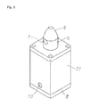
- the spacer 21 has a structure in which the fitting projection 5 is provided at an upper end thereof as in the case of the strut 3 described earlier, the fitting hole 9 is provided in the bottom plate 8, and a height thereof corresponds to a height of the cushioning material 20. Accordingly, by fitting the fitting projection 5 of the strut 3 of the lower rack into the fitting hole 9 of the spacer 21, and fitting the fitting projection 5 of the spacer 21 into the fitting hole 9 of the strut 3 of the upper rack, it is possible to increase the distance between the upper and lower racks by an amount corresponding to the height of the cushioning material 20.
Landscapes
- Chemical & Material Sciences (AREA)
- Chemical Kinetics & Catalysis (AREA)
- Electrochemistry (AREA)
- General Chemical & Material Sciences (AREA)
- Battery Mounting, Suspending (AREA)
- Pallets (AREA)
Abstract
Description
- The present invention relates to a rack for battery packs used for transporting, storing in a warehouse, or installing NaS batteries or other battery packs.
- A battery pack such as a NaS battery, a lithium-ion battery, or a Ni-H2 battery is formed as a battery module by densely arranging a plurality of unit cells in a case. Examples thereof are described in
Patent Documents -
Patent Document 3 describes an example in which battery modules are stored inside a container provided with shelf boards so that the battery modules can be pulled out. However, an actual facility for storing a large amount of power is a large facility that uses several dozens of batter modules. For this reason, when such a facility is newly built, a steel-framed installation rack capable of storing therein several dozens of battery modules is installed at an installation site, and the battery modules transported from a factory are set inside the installation rack one by one using a dedicated tool provided with a hoisting and push-in function. However, since such a dedicated tool is not necessary after completion of the installation, it causes a waste in the cost. Further, constructing the installation rack requires many days and much cost. - Further, since the battery modules are heavy, they are shipped from the factory in a state of being stored with cushioning materials in a steel-framed transportation rack. Since the NaS batteries are often exported overseas, the transportation rack having a sufficient strength to avoid troubles during transportation is used. However, such a transportation rack becomes unnecessary after installing the battery modules in the installation rack, and this involves a lot of cost regardless of whether it is scrapped locally or it is sent back to Japan.
-
- Patent Document 1:
JP 1993-275072 A - Patent Document 2:
JP 1993-275113 A - Patent Document 3:
JP 1993-275114 A - It is an object of the present invention to provide a rack for battery packs which can solve the foregoing conventional problem, reduce a cost necessary for producing an installation rack, reduce a cost incurred in scrapping or returning a transportation rack, and further make possible installation without using a dedicated tool for hoisting and pushing battery modules as in the conventional case.
- According to the present invention achieved to solve the foregoing problem, a rack includes a bottom frame and struts erected at four corners of the bottom frame, and is used for transporting battery modules stored therein. In the rack, a fitting projection is formed at an upper end of each of the struts and a fitting hole into which the fitting projection is fitted is formed in a bottom part of each of the struts. The rack can be used as an installation rack when stacked one on top of another by fitting the fitting projection of each of the struts of a lower rack into the projection hole of each of the struts of an upper rack.
- It is preferable, as recited in
claim 2, that an upper portion of the fitting projection be tapered. - It is preferable, as recited in
claim 3, that a plate-like member for load distribution be arranged between lower ends of the struts that make a pair. It is preferable, as recited inclaim 4, that the plate-like member have a U-shaped cross section with rounded bottom corners thereof. - Further, it is preferable, as recited in
claim 5, that a spacer inserted between each of the struts of the lower rack and each of the struts of the upper rack be provided during transportation or during storage in a warehouse. - The racks for battery packs according to the present invention can be used as the installation racks by stacking up the transportation racks as they are. Therefore, there is no need to install separate installation racks in advance as in the conventional case. Accordingly, it is possible to reduce the manufacturing cost of the installation racks and also to shorten the construction period. In addition, scrapping or returning the transportation racks is not necessary, and therefore the cost incurred in this respect can be also reduced. Furthermore, since the racks for battery packs can be stacked up by using a forklift, the dedicated tool as required in the conventional case is not necessary.
- As recited in
claim 2, by arranging the upper part of the fitting projection in a tapered shape, even if the lower rack and the upper rack slightly deviate from each other, it is easy to fit the fitting projection of the strut of the lower rack into the fitting hole of the strut of the upper rack, and stacking is made possible by positioning the racks. - As recited in
claim 3, by disposing the plate-like member for load distribution between the lower ends of the struts that make a pair, the wooden floor of the container is not damaged during transportation as recited inclaim 4, by arranging the plate-like member to have a U-shaped cross section with rounded bottom corners thereof, the rack tends to slip when pushed into the container or pulled out of the container. - Further, since cushioning members are used when the battery modules are transported or stored in a warehouse, it is necessary to increase a vertical distance between the battery modules than in the case of installation. A height can be adjusted by using the spacer recited in
claim 5. This spacer can be removed during installation. -
-
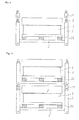
Fig. 1 is a plan view illustrating an embodiment of the present invention. -
Fig. 2 is a front view illustrating the embodiment of the present invention. -
Fig. 3 is a cross sectional view of a strut. -
Fig. 4 is a cross sectional view illustrating a coupling state. -
Fig. 5 is a front view illustrating a stacking state. -
Fig. 6 is a front view of a plate-like member for load distribution. -
Fig. 7 is a perspective view of the plate-like member for load distribution. -
Fig. 8 is a perspective view of a spacer. -
Fig. 9 is a descriptive diagram illustrating attachment of the spacer. -
Fig. 10 is a front view illustrating a state during transportation or storage in a warehouse. - Hereinafter, an embodiment of the present invention will be described with reference to the drawings.
As illustrated inFigs. 1 and 2 , a rack for battery packs according to the present invention is a steel rack for storing therein abattery module 1, and is provided withstruts 3 at four corners of abottom frame 2 that supports thebattery module 1. Thebattery module 1 in this embodiment is a NaS battery, but may be a battery pack of a lithium-ion battery, a Ni-H2 battery, or the like as described earlier. Thebattery module 1 has a rectangular parallelepiped case storing therein several hundred unit cells and hence is heavy.Reference numeral 4 represents a coupling member for connecting between upper parts of thestruts 3, an arrangement thereof is free, and a diagonal coupling member such as a brace may be added. Thebattery module 1 is transported in a state of being stored in such a rack for battery packs. - The
strut 3 of the rack for battery packs according to the present invention is formed of a square steel pipe having a substantially square shape in cross section as illustrated inFig. 3 , afitting projection 5 is provided at an upper end of each of thestruts 3 in a protruding manner. Thefitting projection 5 has a structure in which an upper part of a circular cylinder is arranged as atapered portion 6, and atransverse hole 7 penetrates therethrough. Thefitting projection 5 is welded to the upper end of thestrut 3. Further, afitting hole 9 into which thefitting projection 5 is fitted is formed in abottom plate 8 welded to a bottom part of each of thestruts 3. Also, atransverse hole 10 is formed in the vicinity of a lower end of thestrut 3. - Since the rack for battery packs according to the present invention has the
struts 3 having the structure as described above, the racks for battery packs can be stacked up together by stacking the racks for battery packs vertically, and fitting thefitting projection 5 of thestrut 3 of a lower rack into thefitting hole 9 of thestrut 3 of an upper rack, as illustrated inFig. 4 . This kind of stacking can be made by lifting the rack for battery pack while thebattery modules 1 are stored therein by a forklift, and does not require a dedicated tool as used in the conventional case.Fig. 5 illustrates a state of a three-tier stacking. However, the number of tiers can be arbitrarily increased or decreased. - For this, by arranging the upper part of the
fitting projection 5 as the taperedportion 6, even if the lower rack and the upper rack slightly deviate from each other, it becomes easier to fit thefitting projection 5 of thestrut 3 of the lower rack into thefitting hole 9 of thestrut 3 of the upper rack. Further, stacking is made possible by positioning the upper and lower racks while the taperedportion 6 serves as a guide portion. Thereafter, as illustrated inFig. 4 , abolt 11 is inserted into thetransverse hole 7 of thefitting projection 5 and thetransverse hole 10 at the lower end of thestrut 3, and is fixed by anut 12. Then, a firm stacking without concern about dropping is made possible, and the installation is completed in this state. Although this is not illustrated inFig. 5 , it is also possible to closely arrange the racks for battery packs according to the present invention continuously in a horizontal direction. - As described above, the racks for battery packs according to the present invention use the transportation racks as installation racks by stacking up the transportation racks as they are. For this reason, there is no need to install separate installation racks in advance as in the conventional case. Accordingly, it is possible to reduce the manufacturing cost of the installation racks and also to shorten the construction period. In addition, conventionally, the transportation racks which are no longer necessary after removing the
battery modules 1 are scrapped locally or sent back. However, according to the present invention, such a process is not necessary, and the cost incurred in this respect can be reduced. Further, since the racks for battery packs according to the present invention can be stacked up by using a forklift, the dedicated tool for mounting as required in the conventional case is not necessary, which contributes to further cost reduction. - As described above, the racks for battery packs of the present invention are used as transportation racks and as installation racks, and a container is used during transportation by ship. Since the floor of the container is made of wood, if the rack has a structure in which the four
struts 3 jut out downwardly, a load concentrates thereto, and the floor surface tends to be damaged. Further, when the racks are carried into or out of the long container, the racks for battery packs are pushed in or pulled out by a forklift. However, thestruts 3 dig into the floor surface, and therefore such a work may not be smoothly carried out. - In view of this, as illustrated in
Figs. 6 and 7 , it is preferable to arrange a plate-like member 13 for load distribution between lower ends of thestruts 3 which make a pair (front and rear struts, or right and left struts). In this embodiment, a steel stock having a U-shaped cross section is fixed between the right and leftstruts 3 with bolts. It is also preferable that bottom corners thereof be rounded. When such a plate-like member 13 is used, the wooden floor of the container is not damaged during transportation, and the racks do not dig into the wooden floor when the racks are pushed in or pulled out. - The plate-
like member 13 is useful during transportation, but is not always necessary during installation. Accordingly, it is possible to remove the plate-like member 13 prior to the installation. However, if a fitting hole which is the same as thefitting hole 9 is provided therein, it is possible to install the racks in a state where the plate-like member 13 is fitted thereto. - As illustrated in
Fig. 10 , during transportation and storage in the warehouse,cushioning materials 20 are sandwiched between the upper andlower battery modules 1 to prevent damage. However, thebattery module 1 is raised by an amount of thecushioning material 20, and may interfere with thebottom frame 2 of the upper rack. In addition, thecushioning materials 20 are removed during installation. Therefore, during transportation and storage in the warehouse, it is preferable that aspacer 21 illustrated inFigs. 8 and9 be inserted between thestrut 3 of the lower rack and thestrut 3 of the upper rack to thereby increase a distance between the upper and lower racks, and thespacer 21 be removed during installation to thereby restore the original distance between the upper and lower racks. - The
spacer 21 has a structure in which thefitting projection 5 is provided at an upper end thereof as in the case of thestrut 3 described earlier, thefitting hole 9 is provided in thebottom plate 8, and a height thereof corresponds to a height of thecushioning material 20. Accordingly, by fitting thefitting projection 5 of thestrut 3 of the lower rack into thefitting hole 9 of thespacer 21, and fitting thefitting projection 5 of thespacer 21 into thefitting hole 9 of thestrut 3 of the upper rack, it is possible to increase the distance between the upper and lower racks by an amount corresponding to the height of thecushioning material 20. -
REFERENCE MARKS IN THE DRAWINGS 1 Battery module 2 Bottom frame 3 Strut 4 Coupling member 5 Fitting projection 6 Tapered portion 7 Transverse hole 8 Bottom plate 9 Fitting hole 10 Transverse hole 11 Bolt 12 Nut 13 Plate- like member 20 Cushioning material 21 Spacer
Claims (5)
- A rack for battery pack comprising:a bottom frame; andstruts erected at four corners of the bottom frame, the rack storing therein battery modules to be transported,wherein a fitting projection is formed at an upper end of each of the struts,a fitting hole into which the fitting projection is fitted is formed in a bottom part of each of the struts,the rack for battery pack can be used as an installation rack when stacked one on top of another by fitting the fitting projection of each of the struts of a lower rack into the projection hole of each of the struts of an upper rack.
- The rack for battery pack according to claim 1,
wherein an upper portion of the fitting projection is tapered. - The rack for battery pack according to claim 1,
wherein a plate-like member for load distribution is arranged between lower ends of the struts that make a pair. - The rack for battery pack according to claim 3,
wherein the plate-like member has a U-shaped cross section with rounded bottom corners thereof. - The rack for battery pack according to claim 1,
Wherein a spacer is provided, the spacer being inserted between each of the struts of the lower rack and each of the struts of the upper rack during transportation or during storage in a warehouse.
Applications Claiming Priority (2)
| Application Number | Priority Date | Filing Date | Title |
|---|---|---|---|
| JP2010187216 | 2010-08-24 | ||
| PCT/JP2011/065582 WO2012026224A1 (en) | 2010-08-24 | 2011-07-07 | Battery rack |
Publications (3)
| Publication Number | Publication Date |
|---|---|
| EP2610940A1 true EP2610940A1 (en) | 2013-07-03 |
| EP2610940A4 EP2610940A4 (en) | 2014-08-06 |
| EP2610940B1 EP2610940B1 (en) | 2016-11-23 |
Family
ID=45723237
Family Applications (1)
| Application Number | Title | Priority Date | Filing Date |
|---|---|---|---|
| EP11819695.5A Active EP2610940B1 (en) | 2010-08-24 | 2011-07-07 | Battery rack |
Country Status (5)
| Country | Link |
|---|---|
| US (1) | US9214654B2 (en) |
| EP (1) | EP2610940B1 (en) |
| JP (1) | JP5793765B2 (en) |
| CN (1) | CN103053045B (en) |
| WO (1) | WO2012026224A1 (en) |
Families Citing this family (14)
| Publication number | Priority date | Publication date | Assignee | Title |
|---|---|---|---|---|
| JP5880722B2 (en) * | 2012-09-18 | 2016-03-09 | 日産自動車株式会社 | Assembled battery |
| WO2017056407A1 (en) * | 2015-09-30 | 2017-04-06 | パナソニックIpマネジメント株式会社 | Cell module |
| CN105235691B (en) * | 2015-11-16 | 2017-10-20 | 中车资阳机车有限公司 | A kind of locomotive storage batteries mounting bracket |
| JP6601254B2 (en) * | 2016-02-19 | 2019-11-06 | 株式会社豊田自動織機 | Battery module assembly method and battery module |
| EP3252848B1 (en) | 2016-02-24 | 2019-10-09 | NGK Insulators, Ltd. | Cell device, cell unit, and cell device installation method |
| AU2017201690B2 (en) | 2016-03-14 | 2022-09-15 | The Raymond Corporation | Battery counterweight system |
| JP6698484B2 (en) * | 2016-09-21 | 2020-05-27 | 株式会社エンビジョンAescジャパン | Battery pack |
| CN108550748A (en) * | 2018-06-05 | 2018-09-18 | 安徽艾伊德动力科技有限公司 | A kind of novel power battery echelon utilizes preceding stacking structure |
| DE102018128977B4 (en) * | 2018-11-19 | 2025-02-06 | Dr. Ing. H.C. F. Porsche Aktiengesellschaft | Traction battery arrangement for an electric vehicle and method for assembling such a traction battery arrangement |
| CN110112339B (en) * | 2019-04-10 | 2024-11-12 | 河南超力新能源有限公司 | Power box for starting power supply, starting power supply and preparation method thereof |
| WO2021230542A1 (en) * | 2020-05-11 | 2021-11-18 | 주식회사 엘지에너지솔루션 | Battery module, battery pack comprising same battery module, and vehicle |
| KR102878343B1 (en) * | 2020-09-28 | 2025-10-29 | 주식회사 엘지에너지솔루션 | Battery Rack, Energy Storage System, and Power Generation System |
| JP7622680B2 (en) * | 2022-03-14 | 2025-01-28 | トヨタ自動車株式会社 | Battery case |
| US20240258807A1 (en) * | 2023-01-26 | 2024-08-01 | Global Industrial Distribution Inc. | Modular power system |
Family Cites Families (14)
| Publication number | Priority date | Publication date | Assignee | Title |
|---|---|---|---|---|
| US1355486A (en) * | 1920-10-12 | Cobneb-stay fob beceptacles | ||
| JPS60145550U (en) * | 1984-03-02 | 1985-09-27 | 株式会社ユアサコーポレーション | Storage battery storage device |
| JPH0516051A (en) * | 1991-03-20 | 1993-01-26 | Mitsubishi Electric Corp | Autowork Chain |
| JPH05275114A (en) | 1992-03-24 | 1993-10-22 | Ngk Insulators Ltd | Assembled-type battery |
| JP2552056B2 (en) | 1992-03-24 | 1996-11-06 | 日本碍子株式会社 | High temperature operation type assembled battery |
| JP2554223B2 (en) | 1992-03-25 | 1996-11-13 | 日本碍子株式会社 | Assembled battery |
| DE69304617T2 (en) * | 1992-06-15 | 1997-03-27 | Gnb Ind Battery Co | Modular housing structure for batteries |
| JPH08726U (en) * | 1993-09-22 | 1996-04-23 | 古河電池株式会社 | Storage battery mount |
| US5814968A (en) * | 1995-06-26 | 1998-09-29 | Long Range Systems, Inc. | Battery charger and rechargeable electronic paging device assembly |
| JPH1159688A (en) * | 1997-08-21 | 1999-03-02 | Nissin Electric Co Ltd | Leg body for transfer of heavy box |
| KR100393407B1 (en) | 1998-04-10 | 2003-08-02 | 가부시키가이샤 리코 | An apparatus for transporting and storaging products and the transported products thereby |
| JP3320660B2 (en) * | 1998-08-10 | 2002-09-03 | 株式会社せきづか | Battery tray made of foamed resin |
| JP2000079961A (en) * | 1998-09-01 | 2000-03-21 | Misawa Homes Co Ltd | Method for transporting roof panel with solar battery and device for transporting the same |
| JP2000315521A (en) * | 1999-05-06 | 2000-11-14 | Hitachi Ltd | High temperature sodium secondary battery module and module assembly using the same |
-
2011
- 2011-07-07 CN CN201180038084.2A patent/CN103053045B/en active Active
- 2011-07-07 EP EP11819695.5A patent/EP2610940B1/en active Active
- 2011-07-07 JP JP2012530583A patent/JP5793765B2/en active Active
- 2011-07-07 WO PCT/JP2011/065582 patent/WO2012026224A1/en not_active Ceased
-
2013
- 2013-02-01 US US13/756,762 patent/US9214654B2/en active Active
Also Published As
| Publication number | Publication date |
|---|---|
| JP5793765B2 (en) | 2015-10-14 |
| US20130143092A1 (en) | 2013-06-06 |
| EP2610940A4 (en) | 2014-08-06 |
| JPWO2012026224A1 (en) | 2013-10-28 |
| CN103053045A (en) | 2013-04-17 |
| US9214654B2 (en) | 2015-12-15 |
| WO2012026224A1 (en) | 2012-03-01 |
| EP2610940B1 (en) | 2016-11-23 |
| CN103053045B (en) | 2016-03-30 |
Similar Documents
| Publication | Publication Date | Title |
|---|---|---|
| US9214654B2 (en) | Transportion, storage and installation rack for battery packs | |
| KR101278979B1 (en) | Battery storage device and sub-storage device for the same and battery pack using the same | |
| US8529175B2 (en) | Method for transporting concentrated mass loads by container | |
| JP6484443B2 (en) | Heavy goods transportation and lifting system | |
| CN206610847U (en) | Battery support | |
| KR101350171B1 (en) | The tire moving kit for loading container | |
| CN203372494U (en) | Pipe goods shelf | |
| CN211088333U (en) | Battery rack | |
| CN210654061U (en) | White automobile body loading work or material rest | |
| CN223778795U (en) | Material rack for storing tubular materials | |
| CN104058169B (en) | A kind of tool car Special carrier | |
| CN203937989U (en) | Rolling cart Special carrier | |
| JP2021123865A (en) | Panel loading rack and panel construction method | |
| CN217348688U (en) | Metal packaging frame for generator | |
| CN217515633U (en) | Tray for modularized logistics distribution center | |
| CN219688224U (en) | Goods shelf | |
| CN221419024U (en) | A three-dimensional stacking pallet | |
| CN221189842U (en) | Auxiliary structure for stacking photovoltaic assembly trays | |
| CN220616654U (en) | Turnover frame for battery pack | |
| CN219524618U (en) | Stacked metal particle spare and accessory part containing device | |
| CN214113227U (en) | Universal tray for cylindrical long and high parts | |
| JP2017073231A (en) | Battery stand and battery unit having the same | |
| CN211495232U (en) | Double-deck frame of piling up of superimposed sheet | |
| CN212912314U (en) | Stacked Shelves | |
| CN101085648A (en) | Tray and method for piling cargo using the same |
Legal Events
| Date | Code | Title | Description |
|---|---|---|---|
| PUAI | Public reference made under article 153(3) epc to a published international application that has entered the european phase |
Free format text: ORIGINAL CODE: 0009012 |
|
| 17P | Request for examination filed |
Effective date: 20130215 |
|
| AK | Designated contracting states |
Kind code of ref document: A1 Designated state(s): AL AT BE BG CH CY CZ DE DK EE ES FI FR GB GR HR HU IE IS IT LI LT LU LV MC MK MT NL NO PL PT RO RS SE SI SK SM TR |
|
| DAX | Request for extension of the european patent (deleted) | ||
| A4 | Supplementary search report drawn up and despatched |
Effective date: 20140707 |
|
| RIC1 | Information provided on ipc code assigned before grant |
Ipc: H01M 2/02 20060101ALN20140701BHEP Ipc: A47F 1/00 20060101ALI20140701BHEP Ipc: H01M 2/10 20060101AFI20140701BHEP Ipc: B65D 21/00 20060101ALI20140701BHEP |
|
| GRAP | Despatch of communication of intention to grant a patent |
Free format text: ORIGINAL CODE: EPIDOSNIGR1 |
|
| RIC1 | Information provided on ipc code assigned before grant |
Ipc: H01M 2/10 20060101AFI20160504BHEP Ipc: A47F 1/00 20060101ALI20160504BHEP Ipc: H01M 2/02 20060101ALN20160504BHEP |
|
| RIC1 | Information provided on ipc code assigned before grant |
Ipc: H01M 2/10 20060101AFI20160509BHEP Ipc: A47F 1/00 20060101ALI20160509BHEP Ipc: H01M 2/02 20060101ALN20160509BHEP |
|
| INTG | Intention to grant announced |
Effective date: 20160602 |
|
| RIN1 | Information on inventor provided before grant (corrected) |
Inventor name: TAKEYAMA MIKINE Inventor name: KAMIYA HITOSHI Inventor name: NAGATANI YUTA |
|
| GRAS | Grant fee paid |
Free format text: ORIGINAL CODE: EPIDOSNIGR3 |
|
| GRAA | (expected) grant |
Free format text: ORIGINAL CODE: 0009210 |
|
| AK | Designated contracting states |
Kind code of ref document: B1 Designated state(s): AL AT BE BG CH CY CZ DE DK EE ES FI FR GB GR HR HU IE IS IT LI LT LU LV MC MK MT NL NO PL PT RO RS SE SI SK SM TR |
|
| REG | Reference to a national code |
Ref country code: GB Ref legal event code: FG4D |
|
| REG | Reference to a national code |
Ref country code: CH Ref legal event code: EP |
|
| REG | Reference to a national code |
Ref country code: IE Ref legal event code: FG4D |
|
| REG | Reference to a national code |
Ref country code: AT Ref legal event code: REF Ref document number: 848619 Country of ref document: AT Kind code of ref document: T Effective date: 20161215 |
|
| REG | Reference to a national code |
Ref country code: DE Ref legal event code: R096 Ref document number: 602011032783 Country of ref document: DE |
|
| PG25 | Lapsed in a contracting state [announced via postgrant information from national office to epo] |
Ref country code: LV Free format text: LAPSE BECAUSE OF FAILURE TO SUBMIT A TRANSLATION OF THE DESCRIPTION OR TO PAY THE FEE WITHIN THE PRESCRIBED TIME-LIMIT Effective date: 20161123 |
|
| REG | Reference to a national code |
Ref country code: LT Ref legal event code: MG4D |
|
| REG | Reference to a national code |
Ref country code: NL Ref legal event code: MP Effective date: 20161123 |
|
| REG | Reference to a national code |
Ref country code: AT Ref legal event code: MK05 Ref document number: 848619 Country of ref document: AT Kind code of ref document: T Effective date: 20161123 |
|
| PG25 | Lapsed in a contracting state [announced via postgrant information from national office to epo] |
Ref country code: LT Free format text: LAPSE BECAUSE OF FAILURE TO SUBMIT A TRANSLATION OF THE DESCRIPTION OR TO PAY THE FEE WITHIN THE PRESCRIBED TIME-LIMIT Effective date: 20161123 Ref country code: NL Free format text: LAPSE BECAUSE OF FAILURE TO SUBMIT A TRANSLATION OF THE DESCRIPTION OR TO PAY THE FEE WITHIN THE PRESCRIBED TIME-LIMIT Effective date: 20161123 Ref country code: SE Free format text: LAPSE BECAUSE OF FAILURE TO SUBMIT A TRANSLATION OF THE DESCRIPTION OR TO PAY THE FEE WITHIN THE PRESCRIBED TIME-LIMIT Effective date: 20161123 Ref country code: NO Free format text: LAPSE BECAUSE OF FAILURE TO SUBMIT A TRANSLATION OF THE DESCRIPTION OR TO PAY THE FEE WITHIN THE PRESCRIBED TIME-LIMIT Effective date: 20170223 Ref country code: GR Free format text: LAPSE BECAUSE OF FAILURE TO SUBMIT A TRANSLATION OF THE DESCRIPTION OR TO PAY THE FEE WITHIN THE PRESCRIBED TIME-LIMIT Effective date: 20170224 |
|
| PG25 | Lapsed in a contracting state [announced via postgrant information from national office to epo] |
Ref country code: RS Free format text: LAPSE BECAUSE OF FAILURE TO SUBMIT A TRANSLATION OF THE DESCRIPTION OR TO PAY THE FEE WITHIN THE PRESCRIBED TIME-LIMIT Effective date: 20161123 Ref country code: HR Free format text: LAPSE BECAUSE OF FAILURE TO SUBMIT A TRANSLATION OF THE DESCRIPTION OR TO PAY THE FEE WITHIN THE PRESCRIBED TIME-LIMIT Effective date: 20161123 Ref country code: AT Free format text: LAPSE BECAUSE OF FAILURE TO SUBMIT A TRANSLATION OF THE DESCRIPTION OR TO PAY THE FEE WITHIN THE PRESCRIBED TIME-LIMIT Effective date: 20161123 Ref country code: PL Free format text: LAPSE BECAUSE OF FAILURE TO SUBMIT A TRANSLATION OF THE DESCRIPTION OR TO PAY THE FEE WITHIN THE PRESCRIBED TIME-LIMIT Effective date: 20161123 Ref country code: ES Free format text: LAPSE BECAUSE OF FAILURE TO SUBMIT A TRANSLATION OF THE DESCRIPTION OR TO PAY THE FEE WITHIN THE PRESCRIBED TIME-LIMIT Effective date: 20161123 Ref country code: PT Free format text: LAPSE BECAUSE OF FAILURE TO SUBMIT A TRANSLATION OF THE DESCRIPTION OR TO PAY THE FEE WITHIN THE PRESCRIBED TIME-LIMIT Effective date: 20170323 Ref country code: FI Free format text: LAPSE BECAUSE OF FAILURE TO SUBMIT A TRANSLATION OF THE DESCRIPTION OR TO PAY THE FEE WITHIN THE PRESCRIBED TIME-LIMIT Effective date: 20161123 |
|
| REG | Reference to a national code |
Ref country code: FR Ref legal event code: PLFP Year of fee payment: 7 |
|
| PG25 | Lapsed in a contracting state [announced via postgrant information from national office to epo] |
Ref country code: SK Free format text: LAPSE BECAUSE OF FAILURE TO SUBMIT A TRANSLATION OF THE DESCRIPTION OR TO PAY THE FEE WITHIN THE PRESCRIBED TIME-LIMIT Effective date: 20161123 Ref country code: DK Free format text: LAPSE BECAUSE OF FAILURE TO SUBMIT A TRANSLATION OF THE DESCRIPTION OR TO PAY THE FEE WITHIN THE PRESCRIBED TIME-LIMIT Effective date: 20161123 Ref country code: EE Free format text: LAPSE BECAUSE OF FAILURE TO SUBMIT A TRANSLATION OF THE DESCRIPTION OR TO PAY THE FEE WITHIN THE PRESCRIBED TIME-LIMIT Effective date: 20161123 Ref country code: RO Free format text: LAPSE BECAUSE OF FAILURE TO SUBMIT A TRANSLATION OF THE DESCRIPTION OR TO PAY THE FEE WITHIN THE PRESCRIBED TIME-LIMIT Effective date: 20161123 Ref country code: CZ Free format text: LAPSE BECAUSE OF FAILURE TO SUBMIT A TRANSLATION OF THE DESCRIPTION OR TO PAY THE FEE WITHIN THE PRESCRIBED TIME-LIMIT Effective date: 20161123 |
|
| REG | Reference to a national code |
Ref country code: DE Ref legal event code: R097 Ref document number: 602011032783 Country of ref document: DE |
|
| PG25 | Lapsed in a contracting state [announced via postgrant information from national office to epo] |
Ref country code: BG Free format text: LAPSE BECAUSE OF FAILURE TO SUBMIT A TRANSLATION OF THE DESCRIPTION OR TO PAY THE FEE WITHIN THE PRESCRIBED TIME-LIMIT Effective date: 20170223 Ref country code: BE Free format text: LAPSE BECAUSE OF FAILURE TO SUBMIT A TRANSLATION OF THE DESCRIPTION OR TO PAY THE FEE WITHIN THE PRESCRIBED TIME-LIMIT Effective date: 20161123 Ref country code: SM Free format text: LAPSE BECAUSE OF FAILURE TO SUBMIT A TRANSLATION OF THE DESCRIPTION OR TO PAY THE FEE WITHIN THE PRESCRIBED TIME-LIMIT Effective date: 20161123 Ref country code: IT Free format text: LAPSE BECAUSE OF FAILURE TO SUBMIT A TRANSLATION OF THE DESCRIPTION OR TO PAY THE FEE WITHIN THE PRESCRIBED TIME-LIMIT Effective date: 20161123 |
|
| PLBE | No opposition filed within time limit |
Free format text: ORIGINAL CODE: 0009261 |
|
| STAA | Information on the status of an ep patent application or granted ep patent |
Free format text: STATUS: NO OPPOSITION FILED WITHIN TIME LIMIT |
|
| 26N | No opposition filed |
Effective date: 20170824 |
|
| PG25 | Lapsed in a contracting state [announced via postgrant information from national office to epo] |
Ref country code: SI Free format text: LAPSE BECAUSE OF FAILURE TO SUBMIT A TRANSLATION OF THE DESCRIPTION OR TO PAY THE FEE WITHIN THE PRESCRIBED TIME-LIMIT Effective date: 20161123 |
|
| REG | Reference to a national code |
Ref country code: CH Ref legal event code: PL |
|
| REG | Reference to a national code |
Ref country code: IE Ref legal event code: MM4A |
|
| PG25 | Lapsed in a contracting state [announced via postgrant information from national office to epo] |
Ref country code: CH Free format text: LAPSE BECAUSE OF NON-PAYMENT OF DUE FEES Effective date: 20170731 Ref country code: IE Free format text: LAPSE BECAUSE OF NON-PAYMENT OF DUE FEES Effective date: 20170707 Ref country code: LI Free format text: LAPSE BECAUSE OF NON-PAYMENT OF DUE FEES Effective date: 20170731 |
|
| REG | Reference to a national code |
Ref country code: FR Ref legal event code: PLFP Year of fee payment: 8 |
|
| PG25 | Lapsed in a contracting state [announced via postgrant information from national office to epo] |
Ref country code: LU Free format text: LAPSE BECAUSE OF NON-PAYMENT OF DUE FEES Effective date: 20170707 |
|
| PG25 | Lapsed in a contracting state [announced via postgrant information from national office to epo] |
Ref country code: MT Free format text: LAPSE BECAUSE OF NON-PAYMENT OF DUE FEES Effective date: 20170707 |
|
| PG25 | Lapsed in a contracting state [announced via postgrant information from national office to epo] |
Ref country code: MC Free format text: LAPSE BECAUSE OF FAILURE TO SUBMIT A TRANSLATION OF THE DESCRIPTION OR TO PAY THE FEE WITHIN THE PRESCRIBED TIME-LIMIT Effective date: 20161123 Ref country code: HU Free format text: LAPSE BECAUSE OF FAILURE TO SUBMIT A TRANSLATION OF THE DESCRIPTION OR TO PAY THE FEE WITHIN THE PRESCRIBED TIME-LIMIT; INVALID AB INITIO Effective date: 20110707 |
|
| PG25 | Lapsed in a contracting state [announced via postgrant information from national office to epo] |
Ref country code: CY Free format text: LAPSE BECAUSE OF NON-PAYMENT OF DUE FEES Effective date: 20161123 |
|
| PG25 | Lapsed in a contracting state [announced via postgrant information from national office to epo] |
Ref country code: MK Free format text: LAPSE BECAUSE OF FAILURE TO SUBMIT A TRANSLATION OF THE DESCRIPTION OR TO PAY THE FEE WITHIN THE PRESCRIBED TIME-LIMIT Effective date: 20161123 |
|
| PG25 | Lapsed in a contracting state [announced via postgrant information from national office to epo] |
Ref country code: TR Free format text: LAPSE BECAUSE OF FAILURE TO SUBMIT A TRANSLATION OF THE DESCRIPTION OR TO PAY THE FEE WITHIN THE PRESCRIBED TIME-LIMIT Effective date: 20161123 |
|
| PG25 | Lapsed in a contracting state [announced via postgrant information from national office to epo] |
Ref country code: AL Free format text: LAPSE BECAUSE OF FAILURE TO SUBMIT A TRANSLATION OF THE DESCRIPTION OR TO PAY THE FEE WITHIN THE PRESCRIBED TIME-LIMIT Effective date: 20161123 Ref country code: IS Free format text: LAPSE BECAUSE OF FAILURE TO SUBMIT A TRANSLATION OF THE DESCRIPTION OR TO PAY THE FEE WITHIN THE PRESCRIBED TIME-LIMIT Effective date: 20170323 |
|
| PGFP | Annual fee paid to national office [announced via postgrant information from national office to epo] |
Ref country code: FR Payment date: 20200611 Year of fee payment: 10 |
|
| REG | Reference to a national code |
Ref country code: DE Ref legal event code: R079 Ref document number: 602011032783 Country of ref document: DE Free format text: PREVIOUS MAIN CLASS: H01M0002100000 Ipc: H01M0050200000 |
|
| PG25 | Lapsed in a contracting state [announced via postgrant information from national office to epo] |
Ref country code: FR Free format text: LAPSE BECAUSE OF NON-PAYMENT OF DUE FEES Effective date: 20210731 |
|
| PGFP | Annual fee paid to national office [announced via postgrant information from national office to epo] |
Ref country code: GB Payment date: 20250529 Year of fee payment: 15 |
|
| PGFP | Annual fee paid to national office [announced via postgrant information from national office to epo] |
Ref country code: DE Payment date: 20250528 Year of fee payment: 15 |