EP2610693B1 - Method and apparatus for optimizing energy efficiency of pumping system - Google Patents
Method and apparatus for optimizing energy efficiency of pumping system Download PDFInfo
- Publication number
- EP2610693B1 EP2610693B1 EP11195777.5A EP11195777A EP2610693B1 EP 2610693 B1 EP2610693 B1 EP 2610693B1 EP 11195777 A EP11195777 A EP 11195777A EP 2610693 B1 EP2610693 B1 EP 2610693B1
- Authority
- EP
- European Patent Office
- Prior art keywords
- pump
- head
- basis
- rotational speed
- energy efficiency
- Prior art date
- Legal status (The legal status is an assumption and is not a legal conclusion. Google has not performed a legal analysis and makes no representation as to the accuracy of the status listed.)
- Active
Links
Images




Classifications
-
- F—MECHANICAL ENGINEERING; LIGHTING; HEATING; WEAPONS; BLASTING
- F04—POSITIVE - DISPLACEMENT MACHINES FOR LIQUIDS; PUMPS FOR LIQUIDS OR ELASTIC FLUIDS
- F04B—POSITIVE-DISPLACEMENT MACHINES FOR LIQUIDS; PUMPS
- F04B49/00—Control, e.g. of pump delivery, or pump pressure of, or safety measures for, machines, pumps, or pumping installations, not otherwise provided for, or of interest apart from, groups F04B1/00 - F04B47/00
-
- F—MECHANICAL ENGINEERING; LIGHTING; HEATING; WEAPONS; BLASTING
- F04—POSITIVE - DISPLACEMENT MACHINES FOR LIQUIDS; PUMPS FOR LIQUIDS OR ELASTIC FLUIDS
- F04D—NON-POSITIVE-DISPLACEMENT PUMPS
- F04D13/00—Pumping installations or systems
-
- F—MECHANICAL ENGINEERING; LIGHTING; HEATING; WEAPONS; BLASTING
- F04—POSITIVE - DISPLACEMENT MACHINES FOR LIQUIDS; PUMPS FOR LIQUIDS OR ELASTIC FLUIDS
- F04D—NON-POSITIVE-DISPLACEMENT PUMPS
- F04D15/00—Control, e.g. regulation, of pumps, pumping installations or systems
- F04D15/0066—Control, e.g. regulation, of pumps, pumping installations or systems by changing the speed, e.g. of the driving engine
-
- G—PHYSICS
- G05—CONTROLLING; REGULATING
- G05B—CONTROL OR REGULATING SYSTEMS IN GENERAL; FUNCTIONAL ELEMENTS OF SUCH SYSTEMS; MONITORING OR TESTING ARRANGEMENTS FOR SUCH SYSTEMS OR ELEMENTS
- G05B13/00—Adaptive control systems, i.e. systems automatically adjusting themselves to have a performance which is optimum according to some preassigned criterion
- G05B13/02—Adaptive control systems, i.e. systems automatically adjusting themselves to have a performance which is optimum according to some preassigned criterion electric
Definitions
- the present invention relates to pumps that control fluid level in a reservoir, and particularly to optimizing the energy efficiency of a pumping process.
- a typical application for a pump is filling or emptying a reservoir, such as a water tank, by transferring fluid according to requirements set for the pumping process.
- a reservoir such as a water tank
- Such an application operates on the basis of sensing two surface levels: a high surface level and a low surface level.
- a pump may be started when the high surface level of the reservoir is reached and, correspondingly, the pump may be stopped at the low surface level.
- Fullness or emptiness of the reservoir is typically detected by means of external low- and high-level sensors installed into the reservoir. Fixed-speed pumps are typically used in such applications.
- the energy efficiency of such applications may, however, be poor.
- the fixed-speed pump may be oversized for safety reasons. This may increase the energy consumption of the pumping task unnecessarily. It may be difficult to avoid over-dimensioning when trying to comply with safety requirements for the pumping process. Further, a static head of the pumping process may change during the pumping task. For the above reasons, it can be practically impossible to achieve minimal energy consumption with a fixed-speed operation of a pumping system.
- the energy efficiency can be improved, for instance, by optimizing the pumping process and/or the pumping system components.
- the energy efficiency can also be improved by using an energy-efficient control of the pump operation, for instance, by using a variable-speed drive.
- US patent publication US 2010/0312400 A1 discloses a method and a system for optimizing energy efficiency of a pump arrangement.
- the energy efficiency of the pumping operation is quantified with the term "energy consumption” representing a required amount of energy (or power) to transfer a unit volume of the fluid (this term is also known as the specific energy consumption, E s , in the literature).
- the method tries to find a rotational speed at which the resulting energy consumption of a pumping system is minimal.
- the method and system disclosed in patent publication US 2010/0312400 A1 utilize a permanent or a temporarily installed flow sensor, which is used to determine the energy consumption characteristics of the pump arrangement.
- Flow sensors can, however, be expensive and prone to failure.
- the method disclosed in the US patent publication also does not take into account the effects of changing process parameters, such as the changing static head during pumping, in the selection of the optimum rotational speed.
- a change in the system characteristics may have an effect on the energy consumption characteristics of the pump system and the location of the energy consumption minimum.
- An object of the present invention is to provide a method and an apparatus for implementing the method so as to alleviate the above disadvantages.
- the objects of the invention are achieved by a method and an apparatus, which are characterized by what is stated in the independent claims. Some embodiments of the invention are disclosed in the dependent claims.
- the energy efficiency of a traditional fixed-speed pumping system can be improved by using the disclosed method.
- the disclosed method can be used to improve the operation and energy efficiency of variable-speed-driven pumping systems already equipped with a frequency converter.
- the pumping process is first identified. On the basis of the identified process, energy efficiency optimization characteristics can be formed.
- the pumping system optimization characteristics may, for instance, be represented by the specific energy consumption of the pumping system as a function of the rotational speed of the pump and the static head of the pumping system.
- static head is used for the system static head that the pump needs to overcome to provide flow.
- the optimization characteristics can then be used to minimize energy consumption, for instance, by adjusting the rotational speed of the pump on the basis of the present static head.
- the method can, for instance, be used to compensate possible over-sizing of the pump. Further, the method can be used to adapt the rotational speed of the pump to the changing static head.
- the pumping process identification can be performed without any extra sensors, such as flow rate or pressure difference sensors.
- the implementation of the disclosed method may only require installation of a frequency converter or, alternatively, installation a new firmware into the frequency converter, if it already controls the pumping system operation. Other changes in the pump system are not necessarily required. Both the system identification and rotational speed optimization can be fully automatic operations.
- the energy efficiency of a traditional fixed- or variable-speed pumping system may be improved by using a method capable of adapting to different system characteristics and operating conditions.
- a method for the optimizing energy efficiency of a pumping system that comprises at least one pump controlling a fluid level of a reservoir is disclosed in the following paragraphs. The disclosed method can compensate for possible over-dimensioning of the pump. It can also adapt the operation of the pump to the changing static head, for instance, during the filling up or emptying a reservoir.
- the utilization of the present method does not necessarily require any other major modifications to the existing traditional fixed-speed system. If the operation of the pumping system is already controlled by a frequency converter, updating the firmware of the frequency converter may be enough.
- the disclosed method comprises two stages: a system identification stage and an energy efficiency optimization stage.
- the pumping process is first identified in the system identification stage.
- the system identification stage may be a modified version of the method disclosed in European patent application EP 2 354 556 A1 [1], [2].
- the pumping process can be identified, for instance, by determining pump characteristics for the pump, operating the pump with a range of flow rate conditions, and determining a set of data points, wherein a data point in the set contains information on the system head and the flow rate within the range.
- pump characteristics can be found in the data sheet of the pump published by the manufacturer.
- energy efficiency optimization characteristics can be calculated.
- the optimization characteristics may, for instance, be represented by the specific energy consumption as a function of rotational speed and static head.
- the energy efficiency optimization stage can be performed.
- the optimization characteristics can be used to minimize energy consumption by adjusting a pump control parameter, such as rotational speed or torque, of the pump on the basis of the static head.
- the present static head may, for instance, be determined on the basis of a present system head value. Then, a value for the pump control parameter minimizing the energy consumption can be chosen on the basis of at least the optimization characteristics and the present static head value.
- a frequency converter may, for instance, control the pump on the basis of a chosen rotational speed.
- the pump characteristics and general performance of a pump can be presented by characteristics curves for the head H , shaft power consumption P and efficiency ⁇ as a function of the flow rate Q at a constant rotational speed n 0 .
- Figures 1 a and 1 b illustrate an example of pump characteristics.
- Figure 1a shows a pump QH characteristics curve where the total head of a pump at a nominal rotational speed is represented as a function of flow rate.
- Figure 1b shows a pump QP characteristics curve where the pump shaft power consumption at a nominal rotational speed is represented as a function of flow rate.
- energy efficiency optimization characteristics can be calculated on the basis of the pump characteristics and a set of data points describing system characteristics of the pumping system in question.
- System characteristics of a pumping system may also depend on other parts of the pumping system, such as reservoirs and piping.
- the system characteristics of the pumping system can be described by a curve representing the effect of a vertical fluid lift requirement set for the pump (i.e., static head H st ), and the effect of flow-rate-dependent flow losses (i.e., dynamic head H dyn ) on the system head.
- the static head H st is a term for a vertical fluid lift requirement that can, for instance, comprise a vertical distance between fluid levels of two reservoirs in the pumping system and possibly an ambient pressure difference between the start and end points of the fluid flow.
- the dynamic head H dyn describes the effect of flow-rate-dependent flow losses on the system head.
- the dynamic head has a squared relationship with the flow rate Q of the pump, which is often described using the variable k for flow losses.
- a two-reservoir pumping system that comprises a pump and an interconnecting piping connecting the reservoirs can be regarded as a typical pumping process.
- fluid level of at least one of the reservoirs is changed by transferring the fluid according to the process requirements.
- the system characteristics curve may represent the effect of the vertical distance between the fluid levels of the two reservoirs and the effect of flow-rate-dependent flow losses in the piping on the system head.
- fluid levels may change resulting in a change in static head. Consequently, this may affect the energy efficiency optimization characteristics of a pumping system during the process of filling or emptying a reservoir.
- calculating energy efficiency optimization characteristics may comprise calculating the system characteristics.
- the pump In order to determine the system characteristics, the pump can be operated with a range of flow rate conditions. While operating the pump within a range of conditions, a set of data points can be gathered. The flow rate of the pump can, for instance, be ramped up at startup in the system identification stage in order to scan through a sufficient amount of different flow rate conditions.
- the data points may, for instance, contain information on the system head and a flow rate within the range. This information can, in some cases, be directly obtainable from sensors, such as pressure and flow sensors.
- the flow rate and/or the system head can be determined on the basis of the pump power, pump characteristics, and rotational speed.
- the pump shaft power may first be determined by using Equation 6.
- the flow rate may then be determined with the estimated pump power, pump QP characteristics curve, the estimated rotational speed, and affinity laws.
- the flow rate produced by the pump can be determined from Figure 1b , when the pump shaft power is known.
- the system head may, for instance, be then determined on the basis of the flow rate, pump QH characteristics curve, rotational speed, and affinity laws.
- the model-based estimation method for the pump operating location is well-known [3, 4], and is not further discussed in this disclosure.
- the operation point of the pump can be estimated by utilizing a pressure measurement and the pump characteristics curves.
- the estimation procedure is almost identical to that illustrated in Figure 1b , but the flow rate is instead estimated using the measured head and a given QH curve (see Figure 1a ).
- the QH -curve-based method is already used in frequency converters [4, 5].
- the energy efficiency optimization characteristics of the pump can then be calculated.
- the energy efficiency optimization characteristics can, for instance, be represented by the energy consumption per transferred fluid volume, i.e., the specific energy consumption, as a function of the static head and rotational speed of the pump.
- the energy efficiency optimization stage can be performed.
- the energy consumption can be automatically optimized and monitored.
- the energy efficiency optimization stage comprises choosing a value for a pump control parameter in order to achieve minimum energy consumption.
- the pump control parameter in the energy efficiency optimization stage may, for instance, be the rotational speed or torque of the pump.
- the pump control parameter can, for instance, be chosen on the basis of at least the optimization characteristics and the present static head value.
- the present static head value can be determined, for instance, in a similar manner as the value of the static head during the system identification stage.
- the pump can be operated on the basis of the pump control parameter, thus minimizing the energy consumption.
- Figures 2a and 2b illustrate an exemplary embodiment for emptying a reservoir, in which a pump is started when the fluid level rises to a high limit, and the pump is stopped when the fluid level reaches a low limit.
- Figure 2a shows the pumping system, where a pump 20 is used to pump fluid from a lower reservoir 21 to an upper reservoir 22.
- the fluid level in the upper reservoir 22 is assumed to remain constant.
- the pump 20 controls the fluid level of the lower reservoir.
- a frequency converter 23 operates the pump 20 in the disclosed method. The static head of the system increases when the lower reservoir is being emptied. This results in a change in the most energy efficient rotational speed. The frequency converter 23 is then used to optimize energy-efficiency of the pumping system.
- the disclosed method is also applicable to other reservoir systems, if the system has a typical operating range H st ,1 ... H st ,2 for the static head H st .
- the variable k should also remain constant during the operation of the pump system. In Figure 2a , this means that there should be no flow controlling valves in the pumping system, or the existing valves should not vary k during normal pumping system operation.
- Figure 2b shows the system characteristics curves at the upper and lower limits of the static head (dashed lines identified with H st, 2 and H st, 1 , respectively).
- a change in the static head changes the location of the pump operating point (see arrow B), if the pump is driven at a constant rotational speed.
- the process is first identified in the system identification stage.
- pump characteristics are inputted to the frequency converter.
- the frequency converter also operates the pump within a range of flow rate conditions.
- FIG. 2b further illustrates the system identification stage of the embodiment.
- the system identification stage is divided into two phases.
- the pump 20 is automatically started when the water level reaches a high-level indicator 24.
- the frequency converter 23 ramps up slowly the flow rate of the pump 20 to the nominal rotational speed of the pump, for example. This is shown as phase A in Figure 2b .
- samples of rotational speed and torque estimates ( n est ,1, i , T est ,1, i ) are stored. In Figure 2b , the samples are represented by circles.
- phase B in Figure 2b the pump 20 is run at constant rotational speed until a low-level indicator 25 (in Figure 2a ) signals that the pump 20 should be stopped.
- the rotational speed and torque estimates are sampled at the moment when the low-level indicator 25 in Figure 2a signals the frequency converter 23 to stop pumping.
- the frequency converter 23 can be used to determine a set of data points during the first and the second phase of the system identification stage.
- a data point in the set contains information on a system head and a flow rate within the range. Estimates of the flow rate, Q est,i , and head, H est,i , are formed for each stored data point utilizing, for example, the estimation methods disclosed above.
- the data points can be saved in the memory of a controller of the frequency converter.
- the energy efficiency optimization characteristics can be calculated on the basis of the pump characteristics and the set of data points.
- the frequency converter 23 calculates the energy efficiency optimization characteristics.
- the energy efficiency optimization characteristics are calculated on the on the basis of the pump characteristics and system characteristics.
- the system characteristics represent the limits of the static head ( H st ,1 , H st, 2 ) and the effect of flow rate on the system head (variable k ).
- the system characteristics are calculated on the basis of the set of values of flow rate and system head.
- system characteristics parameters H st ,1 and k can be calculated from stored estimates of rotational speed and torque ( n est ,1, i , T est ,1, i ).
- the static head H st changes as the surface level of the reservoir drops.
- the static head is at its upper limit H st ,2 , thus, having an effect on the location of the pump operating point (now Q est, 2 , H est ,2 ).
- the goal is to minimize the total energy consumption of a pumping task, i.e., the emptying or filling up of a reservoir.
- the energy efficiency optimization automatically compensates for the excessive energy consumption caused by an over-sized pump.
- the rotational speed of the pump is also automatically adjusted according to the current static head.
- a set of curves representing specific energy consumption E s as a function of flow rate Q and rotational speed n can be formed for a range of static head values from H st, 1 to H st, 2 on the basis of the identified system characteristics.
- the pump power consumption P can be defined by utilizing the pump QP characteristics curve, the system characteristics, and the affinity equations.
- the simulation itself is discussed in more detail later in this disclosure.
- the curves represent energy efficiency in the form of specific energy consumption (for instance in Wh/m 3 ) as a function of rotational speed (in rpm).
- each energy efficiency curve has a single rotational speed that results in the minimum specific energy consumption. Consequently, a table of energy efficiency optimization characteristics can be formed, which contains an energy efficiency optimizing rotational speed, or other control parameter values, for each static head.
- the system identification stage is finished, and the energy efficiency optimization stage can be performed.
- the user may have given system limits for the minimum and maximum rotational speed. These may be a result, for example, of a minimum allowed flow velocity of the pumped fluid in the piping, a risk of cavitation, or a maximum time available for the emptying (or filling up) of the reservoir. These are taken into account in the selection of the used rotational speed. If an optimal rotational speed n opt is less than a minimum speed allowed, n min , the minimum allowed rotational speed n min is selected. Correspondingly, if the optimal rotational n opt speed exceeds a maximum speed n max , the maximum rotational speed n max is then selected.
- the optimized operation in the energy efficiency optimization stage in the embodiment of Figures 2a and 2b is as follows.
- the high-level indicator 24 signals the startup of the pump 20.
- the frequency converter 23 starts up, and optimal rotational speed is selected for use on the basis of the minimum static head H st ,1 and possible constraints (i.e., n min and n max ).
- the frequency converter 23 determines a present static head value H st,i periodically by using the pump QP and QH characteristics curves, affinity equations, and identified k (see Equation 8). The frequency converter 23 then chooses the energy consumption minimizing value for a pump control parameter on the basis of at least the optimization characteristics and the present static head value, and operates the pump on the basis of the pump control parameter. Finally, when the reservoir is empty, the low level indicator 25 signals the pump 20 to stop.
- the total energy consumption of each pumping task can be calculated and stored by the frequency converter 23.
- This information in a form of a trend, can be used to detect changes in operating conditions. For example, in sewage systems, mechanical wear and blocking of the pump impeller or piping system may degrade the pumping energy efficiency, thus, leading to an energy consumption that is higher than in normal conditions.
- the frequency converter 23 can be used to detect degradation in pump condition and performance on the basis of a comparison between the present energy consumption and stored information.
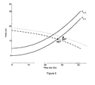
- Figure 3 illustrates energy efficiency curves determined on the basis of the simulation.
- the curves represent energy efficiency in the form of the specific energy consumption, which is here represented by the energy consumption per transferred volume of fluid as a function of rotational speed (in rpm).
- a pump transferred fluid from a lower reservoir to a higher reservoir, thus resulting in a static head H st starting at 5 meters and eventually finishing at 10 meters.
- a constant k of the value 0.0149 was used to represent the flow loss factor.
- the cross-sectional area of the reservoir was 0.75 m 2 , meaning that approximately 3.75 m 3 of water was transferred during a single reservoir emptying task.
- Figures 5a and 5b illustrate the energy consumptions of the proposed linear ramp speed profile and a set of constant rotational speeds between 1000 and 1450 rpm.
- Figure 5b illustrates the durations of a single reservoir emptying task, when using the proposed linear ramp speed profile and a set of constant rotational speeds.
- FIG. 6 illustrates system characteristics curves with the minimum and maximum static heads, and the effect of pump over-sizing on the operating point locations, which are at the intersection of the pump and system head curves.
- the original pump QH characteristics curve is plotted with a dashed line, and the QH curve of the over-sized pump is plotted with a dotted line.
- FIG. 7a illustrates results for the energy consumption of a single reservoir emptying task with different rotational speed profiles.
- Figure 7b illustrates results for the duration of a single reservoir emptying task with the same rotational speed profiles.
- Figure 8a shows the results for a correctly sized pump.
- Figure 8b shows the results for an over-sized pump.
Landscapes
- Engineering & Computer Science (AREA)
- Mechanical Engineering (AREA)
- General Engineering & Computer Science (AREA)
- Health & Medical Sciences (AREA)
- Artificial Intelligence (AREA)
- Computer Vision & Pattern Recognition (AREA)
- Evolutionary Computation (AREA)
- Medical Informatics (AREA)
- Software Systems (AREA)
- Physics & Mathematics (AREA)
- General Physics & Mathematics (AREA)
- Automation & Control Theory (AREA)
- Control Of Non-Positive-Displacement Pumps (AREA)
- Structures Of Non-Positive Displacement Pumps (AREA)
Description
- The present invention relates to pumps that control fluid level in a reservoir, and particularly to optimizing the energy efficiency of a pumping process.
- Pumps are widely used in industrial and municipal applications. A typical application for a pump is filling or emptying a reservoir, such as a water tank, by transferring fluid according to requirements set for the pumping process. Typically, such an application operates on the basis of sensing two surface levels: a high surface level and a low surface level.
- For example, in a wastewater storage system, a pump may be started when the high surface level of the reservoir is reached and, correspondingly, the pump may be stopped at the low surface level. Fullness or emptiness of the reservoir is typically detected by means of external low- and high-level sensors installed into the reservoir. Fixed-speed pumps are typically used in such applications.
- The energy efficiency of such applications may, however, be poor. The fixed-speed pump may be oversized for safety reasons. This may increase the energy consumption of the pumping task unnecessarily. It may be difficult to avoid over-dimensioning when trying to comply with safety requirements for the pumping process. Further, a static head of the pumping process may change during the pumping task. For the above reasons, it can be practically impossible to achieve minimal energy consumption with a fixed-speed operation of a pumping system.
- The energy efficiency can be improved, for instance, by optimizing the pumping process and/or the pumping system components. The energy efficiency can also be improved by using an energy-efficient control of the pump operation, for instance, by using a variable-speed drive.
- US patent publication
US 2010/0312400 A1 discloses a method and a system for optimizing energy efficiency of a pump arrangement. In the publication, the energy efficiency of the pumping operation is quantified with the term "energy consumption" representing a required amount of energy (or power) to transfer a unit volume of the fluid (this term is also known as the specific energy consumption, E s, in the literature). The method tries to find a rotational speed at which the resulting energy consumption of a pumping system is minimal. The method and system disclosed in patent publicationUS 2010/0312400 A1 utilize a permanent or a temporarily installed flow sensor, which is used to determine the energy consumption characteristics of the pump arrangement. - Flow sensors can, however, be expensive and prone to failure. The method disclosed in the US patent publication also does not take into account the effects of changing process parameters, such as the changing static head during pumping, in the selection of the optimum rotational speed. In practice, a change in the system characteristics may have an effect on the energy consumption characteristics of the pump system and the location of the energy consumption minimum.
- An object of the present invention is to provide a method and an apparatus for implementing the method so as to alleviate the above disadvantages. The objects of the invention are achieved by a method and an apparatus, which are characterized by what is stated in the independent claims. Some embodiments of the invention are disclosed in the dependent claims.
- The energy efficiency of a traditional fixed-speed pumping system can be improved by using the disclosed method. In addition, the disclosed method can be used to improve the operation and energy efficiency of variable-speed-driven pumping systems already equipped with a frequency converter.
- In the disclosed method, the pumping process is first identified. On the basis of the identified process, energy efficiency optimization characteristics can be formed. The pumping system optimization characteristics may, for instance, be represented by the specific energy consumption of the pumping system as a function of the rotational speed of the pump and the static head of the pumping system. In the following paragraphs, the term "static head" is used for the system static head that the pump needs to overcome to provide flow.
- The optimization characteristics can then be used to minimize energy consumption, for instance, by adjusting the rotational speed of the pump on the basis of the present static head. The method can, for instance, be used to compensate possible over-sizing of the pump. Further, the method can be used to adapt the rotational speed of the pump to the changing static head.
- By using the disclosed method, the pumping process identification can be performed without any extra sensors, such as flow rate or pressure difference sensors. Thus, the implementation of the disclosed method may only require installation of a frequency converter or, alternatively, installation a new firmware into the frequency converter, if it already controls the pumping system operation. Other changes in the pump system are not necessarily required. Both the system identification and rotational speed optimization can be fully automatic operations.
- In the following, the invention will be described in greater detail by means of preferred embodiments with reference to the attached drawings, in which
-
Figures 1 a and 1 b illustrate an example of pump characteristics; -
Figures 2a and 2b illustrate an exemplary embodiment for emptying a reservoir; -
Figure 3 illustrates simulated specific energy consumption curves; -
Figure 4 illustrates a rotational speed ramp profile used in an embodiment of the disclosed method; -
Figures 5a and 5b illustrate simulated energy consumptions and durations of an exemplary reservoir-emptying application with a linear ramp speed profile and with a set of constant rotational speeds; -
Figure 6 illustrates system characteristics curves and the effect of pump over-sizing on the operating point locations; -
Figures 7a and 7b illustrate energy consumption and duration of a single reservoir-emptying application with different rotational speed profiles; and -
Figures 8a and 8b illustrate simulation results represented as specific energy consumption magnitudes with different rotational speed profiles. - The energy efficiency of a traditional fixed- or variable-speed pumping system may be improved by using a method capable of adapting to different system characteristics and operating conditions. A method for the optimizing energy efficiency of a pumping system that comprises at least one pump controlling a fluid level of a reservoir is disclosed in the following paragraphs.The disclosed method can compensate for possible over-dimensioning of the pump. It can also adapt the operation of the pump to the changing static head, for instance, during the filling up or emptying a reservoir.
- Apart from adding a frequency converter for controlling the pump, the utilization of the present method does not necessarily require any other major modifications to the existing traditional fixed-speed system. If the operation of the pumping system is already controlled by a frequency converter, updating the firmware of the frequency converter may be enough.
- Both the system identification and rotational speed optimization can be fully automatic operations.
- The disclosed method comprises two stages: a system identification stage and an energy efficiency optimization stage. The pumping process is first identified in the system identification stage. The system identification stage may be a modified version of the method disclosed in European
patent application EP 2 354 556 A1 [1], [2]. The pumping process can be identified, for instance, by determining pump characteristics for the pump, operating the pump with a range of flow rate conditions, and determining a set of data points, wherein a data point in the set contains information on the system head and the flow rate within the range. Typically, pump characteristics can be found in the data sheet of the pump published by the manufacturer. - On the basis of the pump characteristics and the set of data points, energy efficiency optimization characteristics can be calculated. The optimization characteristics may, for instance, be represented by the specific energy consumption as a function of rotational speed and static head.
- After the system identification phase, the energy efficiency optimization stage can be performed. At this stage, the optimization characteristics can be used to minimize energy consumption by adjusting a pump control parameter, such as rotational speed or torque, of the pump on the basis of the static head.
- The present static head may, for instance, be determined on the basis of a present system head value. Then, a value for the pump control parameter minimizing the energy consumption can be chosen on the basis of at least the optimization characteristics and the present static head value.
- Finally, the pump can be operated on the basis of the pump control parameter. A frequency converter may, for instance, control the pump on the basis of a chosen rotational speed.
- The pump characteristics and general performance of a pump can be presented by characteristics curves for the head H, shaft power consumption P and efficiency η as a function of the flow rate Q at a constant rotational speed n 0.
Figures 1 a and 1 b illustrate an example of pump characteristics.Figure 1a shows a pump QH characteristics curve where the total head of a pump at a nominal rotational speed is represented as a function of flow rate.Figure 1b shows a pump QP characteristics curve where the pump shaft power consumption at a nominal rotational speed is represented as a function of flow rate. - Since a frequency-converter-driven pump can be operated at various rotational speeds, it may be necessary to convert the pump characteristics curves into the instantaneous rotational speed. This can be performed with affinity laws:


- In order to minimize energy consumption, energy efficiency optimization characteristics can be calculated on the basis of the pump characteristics and a set of data points describing system characteristics of the pumping system in question.
- System characteristics of a pumping system may also depend on other parts of the pumping system, such as reservoirs and piping. The system characteristics of the pumping system can be described by a curve representing the effect of a vertical fluid lift requirement set for the pump (i.e., static head Hst ), and the effect of flow-rate-dependent flow losses (i.e., dynamic head Hdyn ) on the system head.
- The static head Hst is a term for a vertical fluid lift requirement that can, for instance, comprise a vertical distance between fluid levels of two reservoirs in the pumping system and possibly an ambient pressure difference between the start and end points of the fluid flow.
- The dynamic head Hdyn describes the effect of flow-rate-dependent flow losses on the system head. With Newtonian liquids, the dynamic head has a squared relationship with the flow rate Q of the pump, which is often described using the variable k for flow losses.
- Thus, the calculated system characteristics can describe the head requirement set for a pump as a function of flow rate. This requirement is later referred to as the system head Hsys , and it can be calculated as follows:


- A two-reservoir pumping system that comprises a pump and an interconnecting piping connecting the reservoirs can be regarded as a typical pumping process. In the process of filling or emptying a reservoir, fluid level of at least one of the reservoirs is changed by transferring the fluid according to the process requirements.
- In this case, the system characteristics curve may represent the effect of the vertical distance between the fluid levels of the two reservoirs and the effect of flow-rate-dependent flow losses in the piping on the system head. As fluid is transferred from one reservoir to another, fluid levels may change resulting in a change in static head. Consequently, this may affect the energy efficiency optimization characteristics of a pumping system during the process of filling or emptying a reservoir.
- Since the system characteristics are seldom precisely known, calculating energy efficiency optimization characteristics may comprise calculating the system characteristics. In order to determine the system characteristics, the pump can be operated with a range of flow rate conditions. While operating the pump within a range of conditions, a set of data points can be gathered. The flow rate of the pump can, for instance, be ramped up at startup in the system identification stage in order to scan through a sufficient amount of different flow rate conditions. The data points may, for instance, contain information on the system head and a flow rate within the range. This information can, in some cases, be directly obtainable from sensors, such as pressure and flow sensors.
- Alternatively, it is possible to estimate the flow rate and the head. Pump characteristics curves make possible the sensorless estimation of the pump operating point location and efficiency. For instance, determining the set of data points may comprise first determining a rotational speed and a torque of a pump. Estimates of the rotational speed and shaft torque may be available from a frequency converter. The power of the pump can then be determined on the basis of the rotational speed and the torque. Estimated pump power Pest can be, for instance, determined on the basis of the estimated rotational speed nest (in rpm) and the estimated shaft torque Test :

- The flow rate and/or the system head can be determined on the basis of the pump power, pump characteristics, and rotational speed.
- For instance, the pump shaft power may first be determined by using
Equation 6. The flow rate may then be determined with the estimated pump power, pump QP characteristics curve, the estimated rotational speed, and affinity laws. For example, the flow rate produced by the pump can be determined fromFigure 1b , when the pump shaft power is known. The system head may, for instance, be then determined on the basis of the flow rate, pump QH characteristics curve, rotational speed, and affinity laws. The model-based estimation method for the pump operating location is well-known [3, 4], and is not further discussed in this disclosure. - Alternatively, the operation point of the pump can be estimated by utilizing a pressure measurement and the pump characteristics curves. The estimation procedure is almost identical to that illustrated in
Figure 1b , but the flow rate is instead estimated using the measured head and a given QH curve (seeFigure 1a ). The QH-curve-based method is already used in frequency converters [4, 5]. - On the basis of the pump characteristics and system characteristics, the energy efficiency optimization characteristics of the pump can then be calculated. The energy efficiency optimization characteristics can, for instance, be represented by the energy consumption per transferred fluid volume, i.e., the specific energy consumption, as a function of the static head and rotational speed of the pump.
- After the system identification stage is completed, the energy efficiency optimization stage can be performed. During the energy efficiency optimization stage, the energy consumption can be automatically optimized and monitored. The energy efficiency optimization stage comprises choosing a value for a pump control parameter in order to achieve minimum energy consumption. The pump control parameter in the energy efficiency optimization stage may, for instance, be the rotational speed or torque of the pump. The pump control parameter can, for instance, be chosen on the basis of at least the optimization characteristics and the present static head value. The present static head value can be determined, for instance, in a similar manner as the value of the static head during the system identification stage.
- Finally, the pump can be operated on the basis of the pump control parameter, thus minimizing the energy consumption.
-
Figures 2a and 2b illustrate an exemplary embodiment for emptying a reservoir, in which a pump is started when the fluid level rises to a high limit, and the pump is stopped when the fluid level reaches a low limit. -
Figure 2a shows the pumping system, where apump 20 is used to pump fluid from alower reservoir 21 to anupper reservoir 22. The fluid level in theupper reservoir 22 is assumed to remain constant. In other words, thepump 20 controls the fluid level of the lower reservoir. Afrequency converter 23 operates thepump 20 in the disclosed method. The static head of the system increases when the lower reservoir is being emptied. This results in a change in the most energy efficient rotational speed. Thefrequency converter 23 is then used to optimize energy-efficiency of the pumping system. - The assumption that the fluid level in the
upper reservoir 22 remains constant simplifies the determination of the system characteristics, as the static head Hst is then only affected by the change of the fluid level in the lower reservoir. The static head Hst changes within the range H st,1...H st,2. - However, the disclosed method is also applicable to other reservoir systems, if the system has a typical operating range H st,1...H st,2 for the static head Hst . In order to utilize
Equations Figure 2a , this means that there should be no flow controlling valves in the pumping system, or the existing valves should not vary k during normal pumping system operation. -
Figure 2b shows the system characteristics curves at the upper and lower limits of the static head (dashed lines identified with H st,2 and H st,1, respectively). A change in the static head changes the location of the pump operating point (see arrow B), if the pump is driven at a constant rotational speed. - According to the disclosed method, the process is first identified in the system identification stage. For the system identification stage, pump characteristics are inputted to the frequency converter. The frequency converter also operates the pump within a range of flow rate conditions.
-
Figure 2b further illustrates the system identification stage of the embodiment. The system identification stage is divided into two phases. - In the first phase, the
pump 20 is automatically started when the water level reaches a high-level indicator 24. When the startup signal is received, thefrequency converter 23 ramps up slowly the flow rate of thepump 20 to the nominal rotational speed of the pump, for example. This is shown as phase A inFigure 2b . During the first phase, samples of rotational speed and torque estimates (n est,1, i, T est,1,i ) are stored. InFigure 2b , the samples are represented by circles. - In the second phase (phase B in
Figure 2b ) of the system identification stage, thepump 20 is run at constant rotational speed until a low-level indicator 25 (inFigure 2a ) signals that thepump 20 should be stopped. The rotational speed and torque estimates are sampled at the moment when the low-level indicator 25 inFigure 2a signals thefrequency converter 23 to stop pumping. - As estimates of both the rotational speed and the torque are available from the
frequency converter 23 in the embodiment, thefrequency converter 23 can be used to determine a set of data points during the first and the second phase of the system identification stage. A data point in the set contains information on a system head and a flow rate within the range. Estimates of the flow rate, Qest,i , and head, Hest,i , are formed for each stored data point utilizing, for example, the estimation methods disclosed above. The data points can be saved in the memory of a controller of the frequency converter. - After a sufficient amount of data is gathered, the energy efficiency optimization characteristics can be calculated on the basis of the pump characteristics and the set of data points.
- In this embodiment, the
frequency converter 23 calculates the energy efficiency optimization characteristics. The energy efficiency optimization characteristics are calculated on the on the basis of the pump characteristics and system characteristics. The system characteristics represent the limits of the static head (H st,1, H st,2) and the effect of flow rate on the system head (variable k). The system characteristics are calculated on the basis of the set of values of flow rate and system head. - During the first phase of the system identification stage, the static head Hst is at its lowest level and can be considered to be approximately constant. Thus, system characteristics parameters H st,1 and k can be calculated from stored estimates of rotational speed and torque (n est,1,i , T est,1,i ). The calculation can, for instance, be accomplished with the use of a least squares and Simplex method, which minimizes the following equation:

- Correspondingly, during the second phase of the system identification stage, the static head Hst , changes as the surface level of the reservoir drops. When the low surface level is reached, the static head is at its upper limit H st,2 , thus, having an effect on the location of the pump operating point (now Q est,2, H est,2). Because the variable k representing flow friction losses is assumed to remain constant, the upper limit Hst,2 of the static head can be calculated as follows:

- As the upper limit H st,2 and lower limit H st,1 for the static head, together with the variable k representing flow friction are now known, the system characteristics are sufficiently identified for this embodiment to calculate the energy efficiency optimization characteristics.
- In the task of energy efficiency optimization of this embodiment, the goal is to minimize the total energy consumption of a pumping task, i.e., the emptying or filling up of a reservoir. The energy efficiency optimization automatically compensates for the excessive energy consumption caused by an over-sized pump. The rotational speed of the pump is also automatically adjusted according to the current static head.
- A set of curves representing specific energy consumption Es as a function of flow rate Q and rotational speed n can be formed for a range of static head values from H st,1 to H st,2 on the basis of the identified system characteristics. The energy consumption can be calculated as follows:

-
Figure 3 illustrates simulated energy efficiency curves calculated for the process which has a static head ranging between H st,1 = 5 m and H st,2 = 10 m. The simulation itself is discussed in more detail later in this disclosure. The curves represent energy efficiency in the form of specific energy consumption (for instance in Wh/m3) as a function of rotational speed (in rpm). As shown inFigure 3 , each energy efficiency curve has a single rotational speed that results in the minimum specific energy consumption. Consequently, a table of energy efficiency optimization characteristics can be formed, which contains an energy efficiency optimizing rotational speed, or other control parameter values, for each static head. - After the energy efficiency optimization characteristics have been formed, the system identification stage is finished, and the energy efficiency optimization stage can be performed.
- In practice, the user may have given system limits for the minimum and maximum rotational speed. These may be a result, for example, of a minimum allowed flow velocity of the pumped fluid in the piping, a risk of cavitation, or a maximum time available for the emptying (or filling up) of the reservoir. These are taken into account in the selection of the used rotational speed. If an optimal rotational speed nopt is less than a minimum speed allowed, nmin , the minimum allowed rotational speed nmin is selected. Correspondingly, if the optimal rotational nopt speed exceeds a maximum speed nmax , the maximum rotational speed nmax is then selected.
- The optimized operation in the energy efficiency optimization stage in the embodiment of
Figures 2a and 2b is as follows. The high-level indicator 24 signals the startup of thepump 20. Thefrequency converter 23 starts up, and optimal rotational speed is selected for use on the basis of the minimum static head H st,1 and possible constraints (i.e., nmin and nmax ). - The
frequency converter 23 determines a present static head value Hst,i periodically by using the pump QP and QH characteristics curves, affinity equations, and identified k (see Equation 8). Thefrequency converter 23 then chooses the energy consumption minimizing value for a pump control parameter on the basis of at least the optimization characteristics and the present static head value, and operates the pump on the basis of the pump control parameter. Finally, when the reservoir is empty, thelow level indicator 25 signals thepump 20 to stop. - In addition to the conducted rotational speed optimization, the total energy consumption of each pumping task can be calculated and stored by the
frequency converter 23. This information, in a form of a trend, can be used to detect changes in operating conditions. For example, in sewage systems, mechanical wear and blocking of the pump impeller or piping system may degrade the pumping energy efficiency, thus, leading to an energy consumption that is higher than in normal conditions. Thefrequency converter 23 can be used to detect degradation in pump condition and performance on the basis of a comparison between the present energy consumption and stored information. - An implementation of the disclosed method in a reservoir emptying application was simulated using MATLAB software.
Figure 3 illustrates energy efficiency curves determined on the basis of the simulation. The curves represent energy efficiency in the form of the specific energy consumption, which is here represented by the energy consumption per transferred volume of fluid as a function of rotational speed (in rpm). - In the simulation, a pump transferred fluid from a lower reservoir to a higher reservoir, thus resulting in a static head Hst starting at 5 meters and eventually finishing at 10 meters. A constant k of the value 0.0149 was used to represent the flow loss factor. In the simulation, the cross-sectional area of the reservoir was 0.75 m2, meaning that approximately 3.75 m3 of water was transferred during a single reservoir emptying task. The pump was driven by an induction motor and a frequency converter, whose effect on the resulting specific energy consumption Es was ignored in the simulations by selecting η dt = 1 for the drive train efficiency (Equation 9).
- In the simulation, the pump characteristics of a Sulzer APP22-80 centrifugal pump with a 255 mm impeller were used for the pump transferring the fluid to the higher reservoir. Pump characteristics related to the process were such that the pump operated at its best efficiency point (BEP), when the static head Hst was 5 meters and the pump was driven at 1450 rpm. The resulting energy efficiency curves indicate that the optimum rotational speed for the pump was between 815 and 1155 rpm during the reservoir emptying. The constant rotational speed simulations were carried out using a set of constant rotational speeds ranging from 1000 to 1450 rpm. In comparison, a simulation with the linear speed ramp based on the static head Hst of the system and the table of optimum rotational speeds was also carried out.
Figure 4 illustrates the used rotational speed ramp profile. - The use of a ramp-shaped rotational speed profile influenced by the static head Hst seemed to provide further energy savings in comparison to the use of a constant rotational speed during a single reservoir emptying task. Results in respect of the energy consumption and duration with different rotational speed profiles are introduced in
Figures 5a and 5b. Figure 5a illustrates the energy consumptions of the proposed linear ramp speed profile and a set of constant rotational speeds between 1000 and 1450 rpm.Figure 5b illustrates the durations of a single reservoir emptying task, when using the proposed linear ramp speed profile and a set of constant rotational speeds. - Results clearly indicate that the pump operation at the rotational speed of 1450 rpm was not recommendable in terms of energy efficiency, if the process allowed pump operation at a smaller rotational speed. On the other hand, the rotational speed of the pump had to be high enough so that the pump did not operate in a region with a low efficiency and a small flow rate, since the low efficiency and the small flow rate increased the energy consumption and the duration of emptying the reservoir. An example of high-energy consumption and a long duration can be found at constant rotational speed of 1000 rpm in
Figure 5 . - The results also show that the optimum constant (fixed) rotational speed for this application was 1050 rpm where the energy consumption was approximately 161 Wh per emptied reservoir. At this rotational speed, the reservoir was emptied in 307 seconds.
- In comparison with the constant rotational speed of 1050 rpm, the use of a linear ramp speed reference decreased the energy consumption by approximately 11 Wh (7%) per emptied reservoir, resulting in an energy consumption of 150 Wh. On the other hand, emptying the reservoir also took longer, 341 seconds.
- The effect of over-sizing on pump operation, and its compensation by the disclosed method, was studied by using a similar simulation process where a larger impeller with a diameter of 265 mm was used on the pump. Compared with the previous tests, the use of the larger impeller resulted in a 12% increase in the flow rate and a 8% increase in the head produced by the pump.
Figure 6 illustrates system characteristics curves with the minimum and maximum static heads, and the effect of pump over-sizing on the operating point locations, which are at the intersection of the pump and system head curves. The original pump QH characteristics curve is plotted with a dashed line, and the QH curve of the over-sized pump is plotted with a dotted line. Both system characteristics curves (indicated by H st,1 and H st,1) are plotted with solid lines.Figure 6 shows how over-sizing moved the pump operating point locations further away from the best efficiency point BEP denoted by a circle. - The pump specific energy consumption for different static heads was again determined in order to calculate a table of optimal rotational speeds. The table was used to determine an optimum rotational speed profile for the pump during the reservoir emptying.
Figure 7a illustrates results for the energy consumption of a single reservoir emptying task with different rotational speed profiles.Figure 7b illustrates results for the duration of a single reservoir emptying task with the same rotational speed profiles. - The results clearly show the benefits of upgrading a fixed-speed and over-sized pump with a frequency converter that allows an energy efficient control of the pump operation. Compared with the results of
Figure 5 , energy consumption at 1450 rpm was 265 Wh, being 25 Wh (10 %) higher because of the pump over-dimensioning. This difference decreased with a decreasing rotational speed: at optimum constant rotational speed of this system, 1025 rpm, the energy consumption was approximately 167 Wh per emptied reservoir (6 Wh more than in the previous case). At this speed, the reservoir emptied in 286 seconds. - In comparison with the constant rotational speed of 1025 rpm, the use of a linear speed ramp reference ranging from 790 to 1115 rpm decreased the energy consumption by approximately 10 Wh (6%) per emptied reservoir, resulting in an energy consumption of 157 Wh. On the other hand, emptying the reservoir took longer, 318 seconds.
- For a better comparison of the results introduced in
Figures 5 and7 , the results are given as average specific energy consumption magnitudes inFigures 8a and 8b. Figure 8a shows the results for a correctly sized pump.Figure 8b shows the results for an over-sized pump. - It will be obvious to a person skilled in the art that the inventive concept can be implemented in various ways. The invention and its embodiments are not limited to the examples described above, but may vary within the scope of the claims.
-
- [1]
T. Ahonen, J. Tamminen, J. Ahola, ,307 B2, Method in connection with a pump driven with a frequency converter and a frequency converter, Aug. 10, 2011.EP 2 354 556 A1 - [2] T. Ahonen, J. Tamminen, J. Ahola, and J. Kestilä, "Frequency-Converter-Based Hybrid Estimation Method for the Centrifugal Pump Operational State", in IEEE Transactions on Industrial Electronics, Published in IEEE Xplore on Nov. 18, 2011.
- [3]
B. Ohlsson, U. Windecker, S. Zahrai, US 6,918,307 B2 , Device, System and Method for On-line Monitoring of Flow Quantities, Jul. 19, 2005. - [4] T. Ahonen, J. Tamminen, J. Ahola, J. Viholainen, N. Aranto, and J. Kestilä, "Estimation of Pump Operational State With Model-Based Methods", in Energy Conversion and Management Journal, June 2010.
- [5] ABB ACS800 Pump Application Program
Claims (10)
- A method for optimizing energy efficiency of a pumping system comprising at least one pump controlling a fluid level of a reservoir, characterized in that the method comprising a system identification stage and an energy efficiency optimization stage, wherein the system identification stage comprises
determining pump characteristics for the pump,
operating the pump with a range of flow rate conditions, determining a set of data points, wherein a data point in the set contains information on a system head and a flow rate within the range, wherein the system head is a sum of a static head and a dynamic head, where the static head is a vertical fluid lift requirement set for the pump and the dynamic head is an effect of flow-rate dependant flow losses,
calculating system characteristics representing the effects of the static head and the dynamic head on the system head on the basis of the set of data points,
calculating energy efficiency optimization characteristics of the pump on the basis of the pump characteristics and system characteristics, and wherein the energy efficiency optimizing stage is performed after the system identification phase and comprises
determining a present static head value,
choosing an energy consumption minimizing value for a pump control parameter on the basis of at least the optimization characteristics and the present head value,
operating the pump on the pump control parameter. - A method according to claim 1, wherein the energy efficiency optimization characteristics represent energy consumption per volume transferred by the pump as a function of the static head and rotational speed of the pump.
- A method according to claim 1 or 2, wherein determining the set of data points comprises
determining a rotational speed and a torque of a pump,
determining a power of the pump on the basis of the rotational speed and the torque,
determining the flow rate on the basis of the power, pump characteristics, and rotational speed. - A method according to any one of claims 1 to 3, wherein determining the set of data points comprises
determining the system head on the basis of the flow rate, pump characteristics, and rotational speed. - A method according to claim 3, wherein determining the flow rate comprises
determining the flow rate on the basis of the power, pump QP characteristics curve, rotational speed, and affinity laws. - A method according to claim 4, wherein determining the system head comprises
determining the system head on the basis of the flow rate, pump QH characteristics curve, rotational speed, and affinity laws. - A method according to any one of claims 1 to 6, wherein the pump control parameter in the energy efficiency optimization stage is the rotational speed of the pump.
- A method according to any one of claims 1 to 7, wherein operating the pump in the system identification stage comprises ramping up the flow rate of the pump at startup.
- A method according to any one of claims 1 to 8, wherein the method comprises
calculating a present energy consumption during a pumping task,
storing information on the present energy consumption, and
detecting degradation in pump condition and performance on the basis of comparison between the present energy consumption and stored information. - An apparatus for optimizing energy efficiency of a pump system comprising at least one pump controlling a fluid level of a container, characterized by the apparatus comprising, for a system identification stage,
means for determining pump characteristics for the pump,
means for operating the pump with a range of flow rate conditions,
means for determining a set of data points, wherein a data point in the set contains information on a system head and a flow rate within the range, wherein the system head is a sum of a static head and a dynamic head, where the static head is a vertical fluid lift requirement set for the pump and the dynamic head is an effect of flow-rate dependant flow losses,
means for calculating energy efficiency optimization characteristics on the basis of the pump characteristics and the set of data points,
means for calculating system characteristics representing the effects of the static head and the dynamic head on the system head on the basis of the set of data points,
means for calculating energy efficiency optimization characteristics of the pump on the basis of the pump characteristics and system characteristics, and,
for an energy efficiency optimization stage to be performed after the system identification phase,
means for determining a present static head value,
means for choosing an energy consumption minimizing value for a pump control parameter on the basis of at least the optimization characteristics and the present static head value,
means for operating the pump on the basis of the pump control parameter.
Priority Applications (4)
| Application Number | Priority Date | Filing Date | Title |
|---|---|---|---|
| DK11195777.5T DK2610693T3 (en) | 2011-12-27 | 2011-12-27 | Process and apparatus for optimizing energy efficiency of pump system |
| EP11195777.5A EP2610693B1 (en) | 2011-12-27 | 2011-12-27 | Method and apparatus for optimizing energy efficiency of pumping system |
| CN201210576636.1A CN103185003B (en) | 2011-12-27 | 2012-12-26 | For the method and apparatus of the energy efficiency of optimization pumping system |
| US13/728,319 US9382903B2 (en) | 2011-12-27 | 2012-12-27 | Method and apparatus for optimizing energy efficiency of pumping system |
Applications Claiming Priority (1)
| Application Number | Priority Date | Filing Date | Title |
|---|---|---|---|
| EP11195777.5A EP2610693B1 (en) | 2011-12-27 | 2011-12-27 | Method and apparatus for optimizing energy efficiency of pumping system |
Publications (2)
| Publication Number | Publication Date |
|---|---|
| EP2610693A1 EP2610693A1 (en) | 2013-07-03 |
| EP2610693B1 true EP2610693B1 (en) | 2014-12-03 |
Family
ID=45440320
Family Applications (1)
| Application Number | Title | Priority Date | Filing Date |
|---|---|---|---|
| EP11195777.5A Active EP2610693B1 (en) | 2011-12-27 | 2011-12-27 | Method and apparatus for optimizing energy efficiency of pumping system |
Country Status (4)
| Country | Link |
|---|---|
| US (1) | US9382903B2 (en) |
| EP (1) | EP2610693B1 (en) |
| CN (1) | CN103185003B (en) |
| DK (1) | DK2610693T3 (en) |
Cited By (2)
| Publication number | Priority date | Publication date | Assignee | Title |
|---|---|---|---|---|
| US10670024B2 (en) | 2015-06-04 | 2020-06-02 | Fluid Handling Llc | Direct numeric affinity pumps sensorless converter |
| EP4279745A1 (en) | 2022-05-18 | 2023-11-22 | Wilo Se | Method for determining the static head of a pump |
Families Citing this family (21)
| Publication number | Priority date | Publication date | Assignee | Title |
|---|---|---|---|---|
| EP2733358A1 (en) | 2012-11-15 | 2014-05-21 | ABB Oy | Method for approximating the static head downstream of a pump |
| US10138882B1 (en) * | 2013-06-10 | 2018-11-27 | Villicus, Inc. | Controlling a pump |
| FR3014961B1 (en) * | 2013-12-16 | 2019-01-25 | Schneider Toshiba Inverter Europe Sas | CONTROL METHOD FOR MINIMIZING THE CONSUMPTION OF ELECTRICAL ENERGY OF PUMPING EQUIPMENT |
| EP2910788B1 (en) * | 2014-02-25 | 2018-04-04 | TACO ITALIA S.r.l. | Method for controlling a pumping station within a fluid circulation system, related circulation system and pumping station for realizing said method |
| DE102014006828A1 (en) * | 2014-05-13 | 2015-11-19 | Wilo Se | Method for energy-optimal speed control of a pump set |
| EP2947325B1 (en) | 2014-05-23 | 2019-12-04 | Grundfos Holding A/S | Pump control method |
| EP3048305B1 (en) * | 2015-01-20 | 2019-08-21 | Magnussen EMSR-Technik GmbH | Reduction of the energy consumption of a variable speed water pump taking into account the current system load |
| EP3256728B1 (en) | 2015-02-13 | 2021-04-07 | Fluid Handling LLC. | No flow detection means for sensorless pumping control applications |
| DE102017203990A1 (en) * | 2017-03-10 | 2018-09-13 | KSB SE & Co. KGaA | Method for controlling the speed of a centrifugal pump |
| GB201707479D0 (en) * | 2017-05-10 | 2017-06-21 | Severn Trent Water Ltd | Control system for waste water pumping station |
| TR201709660A2 (en) | 2017-06-30 | 2019-01-21 | Deniz Kazanci | FLUID FLOW CONTROLLED SYSTEM INCLUDING AN EXERGY BASED OPTIMAL OUTPUT |
| US11841025B2 (en) * | 2018-03-20 | 2023-12-12 | Enersize Oy | Method for analyzing, monitoring, optimizing and/or comparing energy efficiency in a multiple compressor system |
| ES3041905T3 (en) * | 2018-05-11 | 2025-11-17 | Grundfos Holding As | A monitoring module and method for identifying an operating scenario in a wastewater pumping station |
| DE102018212876A1 (en) * | 2018-08-02 | 2020-02-06 | KSB SE & Co. KGaA | Control method for machine with converter-driven electric drive |
| CN111597687B (en) * | 2020-04-17 | 2024-03-29 | 西安理工大学 | Variable-speed pumped storage unit water pump working condition efficiency optimizing method |
| EP3904682B1 (en) | 2020-04-27 | 2023-11-29 | Xylem Europe GmbH | Method for monitoring and controlling the operation of a pump station |
| US12305650B2 (en) | 2020-07-24 | 2025-05-20 | Eaton Intelligent Power Limited | Control system for a fluid management system |
| EP4293230A1 (en) * | 2022-06-14 | 2023-12-20 | Abb Schweiz Ag | Method for estimating system curve for pump assembly, and power converter system for pump assembly utilizing said method |
| JP7769601B2 (en) * | 2022-12-26 | 2025-11-13 | 株式会社クボタ | Pump control method and pump control device |
| CN119333406B (en) * | 2024-12-24 | 2025-02-28 | 毅飞泵业(福州)有限公司 | Water pump control system based on intelligent water pump data acquisition function |
| BE1032829B1 (en) * | 2025-03-05 | 2026-03-03 | Wilo Se | Method for clearing a blockage in a centrifugal pump |
Family Cites Families (7)
| Publication number | Priority date | Publication date | Assignee | Title |
|---|---|---|---|---|
| SE0103371D0 (en) | 2001-10-09 | 2001-10-09 | Abb Ab | Flow measurements |
| US20100312400A1 (en) | 2007-10-23 | 2010-12-09 | Niels Peder Ledgard Steffensen | Method and pump management system for optimizing the energy consumption in a running fluid transporting pipe system with pumps |
| EP2157317B2 (en) * | 2008-08-19 | 2019-07-24 | ABB Research LTD | Thermoelectric energy storage system and method for storing thermoelectric energy |
| FI20095352A0 (en) * | 2009-04-01 | 2009-04-01 | Abb Oy | Procedure and arrangements for permit monitoring |
| US9181953B2 (en) * | 2009-10-01 | 2015-11-10 | Specific Energy | Controlling pumps for improved energy efficiency |
| EP2354556A1 (en) * | 2010-02-10 | 2011-08-10 | ABB Oy | Method in connection with a pump driven with a frequency converter and a frequency converter |
| CN102052564A (en) * | 2010-10-27 | 2011-05-11 | 杨宝良 | Method for optimizing circulating cooling water convey system |
-
2011
- 2011-12-27 DK DK11195777.5T patent/DK2610693T3/en active
- 2011-12-27 EP EP11195777.5A patent/EP2610693B1/en active Active
-
2012
- 2012-12-26 CN CN201210576636.1A patent/CN103185003B/en active Active
- 2012-12-27 US US13/728,319 patent/US9382903B2/en active Active
Cited By (3)
| Publication number | Priority date | Publication date | Assignee | Title |
|---|---|---|---|---|
| US10670024B2 (en) | 2015-06-04 | 2020-06-02 | Fluid Handling Llc | Direct numeric affinity pumps sensorless converter |
| EP4279745A1 (en) | 2022-05-18 | 2023-11-22 | Wilo Se | Method for determining the static head of a pump |
| LU502112B1 (en) | 2022-05-18 | 2023-12-01 | Wilo Se | Method for determining the static head |
Also Published As
| Publication number | Publication date |
|---|---|
| DK2610693T3 (en) | 2015-02-02 |
| EP2610693A1 (en) | 2013-07-03 |
| US20130164146A1 (en) | 2013-06-27 |
| US9382903B2 (en) | 2016-07-05 |
| CN103185003A (en) | 2013-07-03 |
| CN103185003B (en) | 2015-10-21 |
Similar Documents
| Publication | Publication Date | Title |
|---|---|---|
| EP2610693A1 (en) | Method and apparatus for optimizing energy efficiency of pumping system | |
| RU2702827C2 (en) | Device and method of pump control | |
| US10352293B2 (en) | Fluid system | |
| JP4812327B2 (en) | Water supply equipment | |
| Ahonen et al. | Energy efficiency optimizing speed control method for reservoir pumping applications | |
| JP6848470B2 (en) | Hydropower system | |
| KR102502146B1 (en) | Variable pressure control method of inverter booster pump | |
| JP5323796B2 (en) | Pump device | |
| JP4514558B2 (en) | Pump system | |
| KR101672129B1 (en) | Booster pump control method | |
| JP2009008035A (en) | Variable speed water supply device | |
| JP2000027788A (en) | Operating method of vertical pump and vertical pump | |
| JP2020143626A (en) | Water supply device | |
| JP3556017B2 (en) | Constant flow pump device | |
| EP2562424A2 (en) | Method and equipment for controlling a multipoint fluid distribution system | |
| JPH08159079A (en) | Revolution control water supply system with pressure fluctuation restraining function | |
| KR102330150B1 (en) | Method for shutting off a pump as well as pump station arrangement | |
| JP6490416B2 (en) | Control process for reducing electrical energy consumption of pump equipment | |
| JPH08159078A (en) | Revolution control water supply system with small water quantity stop function | |
| JP4741312B2 (en) | Variable speed water supply device | |
| KR102409922B1 (en) | Inverter for pumps applying sensorless algorithm | |
| KR101605111B1 (en) | Apparatus and method of driving booster pump for saving power | |
| KR101993758B1 (en) | Inverter for pumps applying pressure sensorless algorithm | |
| JP2008101556A (en) | pump | |
| JP4675057B2 (en) | Operation control method for centrifugal pump |
Legal Events
| Date | Code | Title | Description |
|---|---|---|---|
| PUAI | Public reference made under article 153(3) epc to a published international application that has entered the european phase |
Free format text: ORIGINAL CODE: 0009012 |
|
| AK | Designated contracting states |
Kind code of ref document: A1 Designated state(s): AL AT BE BG CH CY CZ DE DK EE ES FI FR GB GR HR HU IE IS IT LI LT LU LV MC MK MT NL NO PL PT RO RS SE SI SK SM TR |
|
| AX | Request for extension of the european patent |
Extension state: BA ME |
|
| 17P | Request for examination filed |
Effective date: 20131219 |
|
| RBV | Designated contracting states (corrected) |
Designated state(s): AL AT BE BG CH CY CZ DE DK EE ES FI FR GB GR HR HU IE IS IT LI LT LU LV MC MK MT NL NO PL PT RO RS SE SI SK SM TR |
|
| RIC1 | Information provided on ipc code assigned before grant |
Ipc: G05B 13/02 20060101AFI20140528BHEP Ipc: F04D 15/00 20060101ALI20140528BHEP Ipc: F04D 13/00 20060101ALI20140528BHEP |
|
| GRAP | Despatch of communication of intention to grant a patent |
Free format text: ORIGINAL CODE: EPIDOSNIGR1 |
|
| INTG | Intention to grant announced |
Effective date: 20140710 |
|
| GRAS | Grant fee paid |
Free format text: ORIGINAL CODE: EPIDOSNIGR3 |
|
| GRAA | (expected) grant |
Free format text: ORIGINAL CODE: 0009210 |
|
| AK | Designated contracting states |
Kind code of ref document: B1 Designated state(s): AL AT BE BG CH CY CZ DE DK EE ES FI FR GB GR HR HU IE IS IT LI LT LU LV MC MK MT NL NO PL PT RO RS SE SI SK SM TR |
|
| REG | Reference to a national code |
Ref country code: GB Ref legal event code: FG4D |
|
| REG | Reference to a national code |
Ref country code: AT Ref legal event code: REF Ref document number: 699712 Country of ref document: AT Kind code of ref document: T Effective date: 20141215 Ref country code: CH Ref legal event code: EP |
|
| REG | Reference to a national code |
Ref country code: IE Ref legal event code: FG4D |
|
| REG | Reference to a national code |
Ref country code: DE Ref legal event code: R096 Ref document number: 602011011868 Country of ref document: DE Effective date: 20150115 |
|
| REG | Reference to a national code |
Ref country code: DK Ref legal event code: T3 Effective date: 20150129 |
|
| REG | Reference to a national code |
Ref country code: NL Ref legal event code: VDEP Effective date: 20141203 |
|
| REG | Reference to a national code |
Ref country code: AT Ref legal event code: MK05 Ref document number: 699712 Country of ref document: AT Kind code of ref document: T Effective date: 20141203 |
|
| PG25 | Lapsed in a contracting state [announced via postgrant information from national office to epo] |
Ref country code: NL Free format text: LAPSE BECAUSE OF FAILURE TO SUBMIT A TRANSLATION OF THE DESCRIPTION OR TO PAY THE FEE WITHIN THE PRESCRIBED TIME-LIMIT Effective date: 20141203 Ref country code: LT Free format text: LAPSE BECAUSE OF FAILURE TO SUBMIT A TRANSLATION OF THE DESCRIPTION OR TO PAY THE FEE WITHIN THE PRESCRIBED TIME-LIMIT Effective date: 20141203 Ref country code: NO Free format text: LAPSE BECAUSE OF FAILURE TO SUBMIT A TRANSLATION OF THE DESCRIPTION OR TO PAY THE FEE WITHIN THE PRESCRIBED TIME-LIMIT Effective date: 20150303 Ref country code: ES Free format text: LAPSE BECAUSE OF FAILURE TO SUBMIT A TRANSLATION OF THE DESCRIPTION OR TO PAY THE FEE WITHIN THE PRESCRIBED TIME-LIMIT Effective date: 20141203 |
|
| REG | Reference to a national code |
Ref country code: LT Ref legal event code: MG4D |
|
| PG25 | Lapsed in a contracting state [announced via postgrant information from national office to epo] |
Ref country code: LV Free format text: LAPSE BECAUSE OF FAILURE TO SUBMIT A TRANSLATION OF THE DESCRIPTION OR TO PAY THE FEE WITHIN THE PRESCRIBED TIME-LIMIT Effective date: 20141203 Ref country code: RS Free format text: LAPSE BECAUSE OF FAILURE TO SUBMIT A TRANSLATION OF THE DESCRIPTION OR TO PAY THE FEE WITHIN THE PRESCRIBED TIME-LIMIT Effective date: 20141203 Ref country code: CY Free format text: LAPSE BECAUSE OF FAILURE TO SUBMIT A TRANSLATION OF THE DESCRIPTION OR TO PAY THE FEE WITHIN THE PRESCRIBED TIME-LIMIT Effective date: 20141203 Ref country code: SE Free format text: LAPSE BECAUSE OF FAILURE TO SUBMIT A TRANSLATION OF THE DESCRIPTION OR TO PAY THE FEE WITHIN THE PRESCRIBED TIME-LIMIT Effective date: 20141203 Ref country code: GR Free format text: LAPSE BECAUSE OF FAILURE TO SUBMIT A TRANSLATION OF THE DESCRIPTION OR TO PAY THE FEE WITHIN THE PRESCRIBED TIME-LIMIT Effective date: 20150304 Ref country code: HR Free format text: LAPSE BECAUSE OF FAILURE TO SUBMIT A TRANSLATION OF THE DESCRIPTION OR TO PAY THE FEE WITHIN THE PRESCRIBED TIME-LIMIT Effective date: 20141203 Ref country code: AT Free format text: LAPSE BECAUSE OF FAILURE TO SUBMIT A TRANSLATION OF THE DESCRIPTION OR TO PAY THE FEE WITHIN THE PRESCRIBED TIME-LIMIT Effective date: 20141203 |
|
| PG25 | Lapsed in a contracting state [announced via postgrant information from national office to epo] |
Ref country code: BE Free format text: LAPSE BECAUSE OF NON-PAYMENT OF DUE FEES Effective date: 20141231 |
|
| PG25 | Lapsed in a contracting state [announced via postgrant information from national office to epo] |
Ref country code: RO Free format text: LAPSE BECAUSE OF FAILURE TO SUBMIT A TRANSLATION OF THE DESCRIPTION OR TO PAY THE FEE WITHIN THE PRESCRIBED TIME-LIMIT Effective date: 20141203 Ref country code: SK Free format text: LAPSE BECAUSE OF FAILURE TO SUBMIT A TRANSLATION OF THE DESCRIPTION OR TO PAY THE FEE WITHIN THE PRESCRIBED TIME-LIMIT Effective date: 20141203 Ref country code: PT Free format text: LAPSE BECAUSE OF FAILURE TO SUBMIT A TRANSLATION OF THE DESCRIPTION OR TO PAY THE FEE WITHIN THE PRESCRIBED TIME-LIMIT Effective date: 20150403 Ref country code: CZ Free format text: LAPSE BECAUSE OF FAILURE TO SUBMIT A TRANSLATION OF THE DESCRIPTION OR TO PAY THE FEE WITHIN THE PRESCRIBED TIME-LIMIT Effective date: 20141203 Ref country code: EE Free format text: LAPSE BECAUSE OF FAILURE TO SUBMIT A TRANSLATION OF THE DESCRIPTION OR TO PAY THE FEE WITHIN THE PRESCRIBED TIME-LIMIT Effective date: 20141203 |
|
| REG | Reference to a national code |
Ref country code: CH Ref legal event code: PL |
|
| PG25 | Lapsed in a contracting state [announced via postgrant information from national office to epo] |
Ref country code: PL Free format text: LAPSE BECAUSE OF FAILURE TO SUBMIT A TRANSLATION OF THE DESCRIPTION OR TO PAY THE FEE WITHIN THE PRESCRIBED TIME-LIMIT Effective date: 20141203 Ref country code: IS Free format text: LAPSE BECAUSE OF FAILURE TO SUBMIT A TRANSLATION OF THE DESCRIPTION OR TO PAY THE FEE WITHIN THE PRESCRIBED TIME-LIMIT Effective date: 20150403 |
|
| REG | Reference to a national code |
Ref country code: DE Ref legal event code: R097 Ref document number: 602011011868 Country of ref document: DE |
|
| REG | Reference to a national code |
Ref country code: IE Ref legal event code: MM4A |
|
| PG25 | Lapsed in a contracting state [announced via postgrant information from national office to epo] |
Ref country code: MC Free format text: LAPSE BECAUSE OF FAILURE TO SUBMIT A TRANSLATION OF THE DESCRIPTION OR TO PAY THE FEE WITHIN THE PRESCRIBED TIME-LIMIT Effective date: 20141203 |
|
| PLBE | No opposition filed within time limit |
Free format text: ORIGINAL CODE: 0009261 |
|
| STAA | Information on the status of an ep patent application or granted ep patent |
Free format text: STATUS: NO OPPOSITION FILED WITHIN TIME LIMIT |
|
| PG25 | Lapsed in a contracting state [announced via postgrant information from national office to epo] |
Ref country code: CH Free format text: LAPSE BECAUSE OF NON-PAYMENT OF DUE FEES Effective date: 20141231 Ref country code: IE Free format text: LAPSE BECAUSE OF NON-PAYMENT OF DUE FEES Effective date: 20141227 Ref country code: LI Free format text: LAPSE BECAUSE OF NON-PAYMENT OF DUE FEES Effective date: 20141231 |
|
| 26N | No opposition filed |
Effective date: 20150904 |
|
| REG | Reference to a national code |
Ref country code: FR Ref legal event code: PLFP Year of fee payment: 5 |
|
| PG25 | Lapsed in a contracting state [announced via postgrant information from national office to epo] |
Ref country code: SI Free format text: LAPSE BECAUSE OF FAILURE TO SUBMIT A TRANSLATION OF THE DESCRIPTION OR TO PAY THE FEE WITHIN THE PRESCRIBED TIME-LIMIT Effective date: 20141203 |
|
| PG25 | Lapsed in a contracting state [announced via postgrant information from national office to epo] |
Ref country code: SM Free format text: LAPSE BECAUSE OF FAILURE TO SUBMIT A TRANSLATION OF THE DESCRIPTION OR TO PAY THE FEE WITHIN THE PRESCRIBED TIME-LIMIT Effective date: 20141203 |
|
| PG25 | Lapsed in a contracting state [announced via postgrant information from national office to epo] |
Ref country code: BE Free format text: LAPSE BECAUSE OF FAILURE TO SUBMIT A TRANSLATION OF THE DESCRIPTION OR TO PAY THE FEE WITHIN THE PRESCRIBED TIME-LIMIT Effective date: 20141203 |
|
| PG25 | Lapsed in a contracting state [announced via postgrant information from national office to epo] |
Ref country code: BG Free format text: LAPSE BECAUSE OF FAILURE TO SUBMIT A TRANSLATION OF THE DESCRIPTION OR TO PAY THE FEE WITHIN THE PRESCRIBED TIME-LIMIT Effective date: 20141203 |
|
| PG25 | Lapsed in a contracting state [announced via postgrant information from national office to epo] |
Ref country code: MT Free format text: LAPSE BECAUSE OF FAILURE TO SUBMIT A TRANSLATION OF THE DESCRIPTION OR TO PAY THE FEE WITHIN THE PRESCRIBED TIME-LIMIT Effective date: 20141203 Ref country code: HU Free format text: LAPSE BECAUSE OF FAILURE TO SUBMIT A TRANSLATION OF THE DESCRIPTION OR TO PAY THE FEE WITHIN THE PRESCRIBED TIME-LIMIT; INVALID AB INITIO Effective date: 20111227 Ref country code: TR Free format text: LAPSE BECAUSE OF FAILURE TO SUBMIT A TRANSLATION OF THE DESCRIPTION OR TO PAY THE FEE WITHIN THE PRESCRIBED TIME-LIMIT Effective date: 20141203 Ref country code: LU Free format text: LAPSE BECAUSE OF NON-PAYMENT OF DUE FEES Effective date: 20141227 |
|
| REG | Reference to a national code |
Ref country code: FR Ref legal event code: PLFP Year of fee payment: 6 |
|
| REG | Reference to a national code |
Ref country code: FR Ref legal event code: PLFP Year of fee payment: 7 |
|
| PG25 | Lapsed in a contracting state [announced via postgrant information from national office to epo] |
Ref country code: MK Free format text: LAPSE BECAUSE OF FAILURE TO SUBMIT A TRANSLATION OF THE DESCRIPTION OR TO PAY THE FEE WITHIN THE PRESCRIBED TIME-LIMIT Effective date: 20141203 |
|
| REG | Reference to a national code |
Ref country code: GB Ref legal event code: 732E Free format text: REGISTERED BETWEEN 20180823 AND 20180829 |
|
| REG | Reference to a national code |
Ref country code: DE Ref legal event code: R081 Ref document number: 602011011868 Country of ref document: DE Owner name: ABB SCHWEIZ AG, CH Free format text: FORMER OWNER: ABB OY, HELSINKI, FI |
|
| PG25 | Lapsed in a contracting state [announced via postgrant information from national office to epo] |
Ref country code: AL Free format text: LAPSE BECAUSE OF FAILURE TO SUBMIT A TRANSLATION OF THE DESCRIPTION OR TO PAY THE FEE WITHIN THE PRESCRIBED TIME-LIMIT Effective date: 20141203 |
|
| PGFP | Annual fee paid to national office [announced via postgrant information from national office to epo] |
Ref country code: DE Payment date: 20251211 Year of fee payment: 15 |
|
| PGFP | Annual fee paid to national office [announced via postgrant information from national office to epo] |
Ref country code: GB Payment date: 20251219 Year of fee payment: 15 |
|
| PGFP | Annual fee paid to national office [announced via postgrant information from national office to epo] |
Ref country code: IT Payment date: 20251223 Year of fee payment: 15 Ref country code: FI Payment date: 20251223 Year of fee payment: 15 Ref country code: DK Payment date: 20251224 Year of fee payment: 15 |
|
| PGFP | Annual fee paid to national office [announced via postgrant information from national office to epo] |
Ref country code: FR Payment date: 20251223 Year of fee payment: 15 |