EP2610556A2 - Odour filter for a range hood, and related range hood - Google Patents
Odour filter for a range hood, and related range hood Download PDFInfo
- Publication number
- EP2610556A2 EP2610556A2 EP12199492.5A EP12199492A EP2610556A2 EP 2610556 A2 EP2610556 A2 EP 2610556A2 EP 12199492 A EP12199492 A EP 12199492A EP 2610556 A2 EP2610556 A2 EP 2610556A2
- Authority
- EP
- European Patent Office
- Prior art keywords
- filter
- housings
- hood
- air
- inlet
- Prior art date
- Legal status (The legal status is an assumption and is not a legal conclusion. Google has not performed a legal analysis and makes no representation as to the accuracy of the status listed.)
- Withdrawn
Links
- 238000001914 filtration Methods 0.000 claims abstract description 51
- OKTJSMMVPCPJKN-UHFFFAOYSA-N Carbon Chemical compound [C] OKTJSMMVPCPJKN-UHFFFAOYSA-N 0.000 claims description 33
- 239000003517 fume Substances 0.000 claims description 14
- 229920000877 Melamine resin Polymers 0.000 claims description 6
- 239000011358 absorbing material Substances 0.000 claims description 6
- IVJISJACKSSFGE-UHFFFAOYSA-N formaldehyde;1,3,5-triazine-2,4,6-triamine Chemical compound O=C.NC1=NC(N)=NC(N)=N1 IVJISJACKSSFGE-UHFFFAOYSA-N 0.000 claims description 6
- 239000006260 foam Substances 0.000 claims description 4
- 239000004480 active ingredient Substances 0.000 claims 1
- 230000003134 recirculating effect Effects 0.000 description 8
- 238000009423 ventilation Methods 0.000 description 4
- 238000000605 extraction Methods 0.000 description 3
- 239000000463 material Substances 0.000 description 3
- 239000002245 particle Substances 0.000 description 3
- 230000007423 decrease Effects 0.000 description 2
- 238000012423 maintenance Methods 0.000 description 2
- 239000000126 substance Substances 0.000 description 2
- TVEXGJYMHHTVKP-UHFFFAOYSA-N 6-oxabicyclo[3.2.1]oct-3-en-7-one Chemical compound C1C2C(=O)OC1C=CC2 TVEXGJYMHHTVKP-UHFFFAOYSA-N 0.000 description 1
- 241000826860 Trapezium Species 0.000 description 1
- 230000005534 acoustic noise Effects 0.000 description 1
- 239000003242 anti bacterial agent Substances 0.000 description 1
- 230000000844 anti-bacterial effect Effects 0.000 description 1
- 230000033228 biological regulation Effects 0.000 description 1
- 229910052799 carbon Inorganic materials 0.000 description 1
- 238000010411 cooking Methods 0.000 description 1
- 230000003247 decreasing effect Effects 0.000 description 1
- 239000002781 deodorant agent Substances 0.000 description 1
- 238000007599 discharging Methods 0.000 description 1
- 230000008030 elimination Effects 0.000 description 1
- 238000003379 elimination reaction Methods 0.000 description 1
- 230000007613 environmental effect Effects 0.000 description 1
- 238000003780 insertion Methods 0.000 description 1
- 230000037431 insertion Effects 0.000 description 1
- 238000009434 installation Methods 0.000 description 1
- 239000007788 liquid Substances 0.000 description 1
- 239000002304 perfume Substances 0.000 description 1
- 239000007787 solid Substances 0.000 description 1
Images



Classifications
-
- F—MECHANICAL ENGINEERING; LIGHTING; HEATING; WEAPONS; BLASTING
- F24—HEATING; RANGES; VENTILATING
- F24C—DOMESTIC STOVES OR RANGES ; DETAILS OF DOMESTIC STOVES OR RANGES, OF GENERAL APPLICATION
- F24C15/00—Details
- F24C15/20—Removing cooking fumes
- F24C15/2035—Arrangement or mounting of filters
Definitions
- the present invention relates to the field of extraction or recirculating hoods, in particular for treating fumes and odours in household environments, e.g. a range hood.
- the invention relates in particular to an odour filter for a hood, as well as to an associated hood.
- Aspirating and/or filtering devices are known which are to be installed near places where fumes or odours are generated.
- such aspirating and/or filtering devices are called “hoods” and are typically installed in household environments, such as a kitchen.
- the term "fumes” designates an aeriform substance, typically air, contaminated by suspended liquid, solid or ethereal particles.
- the aspirated fumes typically transport suspended greasy particles and odours generated by food being cooked.
- hoods take in fumes from the environment, discharging the aspirated air into a ventilation duct, which then evacuates both fumes and odours out in the open; such hoods are hence referred to as "extraction hoods”.
- hoods collect fumes from the environment, filter them, and then reintroduce purified air into the same environment; hoods of this latter type are called “recirculating hoods", and the present invention proves to be especially advantageous for such recirculating hoods.
- a recirculating hood is known from document WO2009062809A2 , which describes a hood that comprises an air inlet opening connected to a chimney-like discharge element.
- the discharge element comprises a filter for filtering aspirated fumes/odours; the filter comprises activated-carbon elements for odour elimination, and the filter area is increased in order to ensure the utmost efficiency.
- a hood filter is known from document WO2011064083A1 , which describes a filter comprising an activated-carbon odour filter in which there are a plurality of recesses for improving the filtering performance.
- the filter elements in particular activated-carbon filter elements, used in known hood filters have however a tendency to lose effectiveness after a certain number of working hours, since the adsorbing power of the activated carbon decreases as air keeps flowing through the odour filter, leading to reduced effectiveness of the filter as a whole.
- the user must therefore take action by replacing or reconditioning the exhausted filter elements, so as to restore the filter to its full effectiveness.
- Prior-art filters are, in fact, not easily accessible to the user, and require the user to carry out delicate and uncomfortable operations in order to install and remove the filters and replace the filter elements.
- hood filters known in the art also suffer from the drawback that they cannot fully exploit their filter elements.
- activated-carbon filters have a tendency to lose effectiveness after a certain number of working hours, since the adsorbing power of the activated carbon decreases as air keeps flowing through the odour filter, leading to reduced effectiveness of the filter as a whole.
- a hood filter which comprises a plurality of housings, each adapted to receive a respective filter element, wherein said plurality of housings are in side-by-side relation and define a filtering surface, and an air inlet for introducing air the be filtered into said filter.
- the plurality of housings are arranged in the filter around at least a part of the perimeter of said air inlet, thereby defining a side filtering surface, wherein each one of the housings comprises a pair of longitudinal guides adapted to hold the respective filter element in place, and an opening for inserting the filter element into the pair of guides, the opening being located at the guides' end which is opposite to the air inlet.
- This solution allows to obtain a filter having a simple and compact configuration, wherein the filter elements can be inserted without difficulty into the filter structure and can be replaced quickly.
- the filter comprises a closing surface opposite to said air inlet, said closing surface being removable by the user.
- the filter structure ensures effective air filtering as well as, when removed, easy access to the filter elements.
- each one of the housings face towards the closing surface. In this manner, when the user opens the filter by removing the closing surface, he/she will gain easy access to the openings for replacing the filter elements.
- the side filtering surface is divergent, the width of said housings at the closing surface being greater than the width of the housings at the air inlet.
- the filter can house trapezoidal filter elements with their major base located at the housing opening, thus making the filter elements themselves easier to replace.
- a hood filter which comprises a plurality of housings, each adapted to receive a respective filter element, wherein said plurality of housings are in side-by-side relation and define a filtering surface, and an inlet for introducing air the be filtered into said filter.
- the filter further comprises an internal baffle element adapted to fluid-dynamically interact with the air coming from said inlet and direct it towards said filtering surface.
- the baffle element allows to convey the air to be filtered directly towards the filter elements, so as to use the whole surface thereof. This ensures a more effective utilization of each filter element, reducing wear and maintenance thereof. At the same time, the filtering performance of the filter is increased when installed in a hood, since its filtering area is maximized.
- the plurality of housings are arranged at least partially with cylindrical symmetry within the filter, thereby defining a side filtering surface, wherein said inlet is in a transverse position at an edge of said side filtering surface, and said baffle element has a pyramidal shape, with its base attached to a surface of said filter opposite to said inlet.
- the side filtering surface is divergent, a diameter thereof at said surface opposite to said inlet being greater than the diameter at said inlet.
- the baffle element preferably comprises a plurality of side faces respectively facing towards each one of said filter elements.
- the baffle element is made of sound-absorbing material.
- the filter when installed in a recirculating hood, it will contribute to dampening the noise generated by the ventilation means associated with the hood, thus reducing the noise produced by the hood as a whole when in operation.
- the sound-absorbing material comprises a melamine-formaldehyde foam, which is particularly suited for household use.
- the filter elements comprise active carbon on their surfaces, so as to further remove any odours from the filtered air.
- the filter is to be installed in a hood, preferably by positioning it downstream of the ventilation means.
- the hood comprises an access to a ventilation chimney, whereon the filter is located, with the air inlet in fluidic connection with the chimney and the filter closing surface facing outwards.
- FIG 1 shows one example of a range hood 101 of the recirculating type.
- the hood 101 comprises a converging fume collector 102 to be typically positioned above a cooking top, in the case of a range hood.
- the fume collector 102 may comprise at its inlet further filter elements (not shown) adapted to filter any greasy particles dragged along by the air, which elements are filters in accordance with the teachings of the prior art.
- the hood 101 is of the "island” type, i.e. it is installed at a distance from the room walls and is accessible on all four sides.
- the hood 101 further comprises air circulating means 103, e.g. a compressor or a fan, adapted to collect air from the fume collector 102 and convey it into the chimney 104.
- air circulating means 103 e.g. a compressor or a fan
- the filter 105 comprises a plurality of filter elements adapted to create a filtering surface, in particular in order to purify the air collected by the hood 101 from any ethereal substances carrying unpleasant odours.
- the filter 105 is masked by the aesthetic appendix 106, which hides it from view to any users in the room where the hood 101 is located.
- the hood 101 is of the "recirculating" type; therefore, the air collected by the fume collector 102, once purified, is reintroduced into the same environment.
- the filter 105 comprises a structure adapted to house a plurality of filter elements, preferably flat activated-carbon cartridges.
- the filter 105 comprises six flat filter elements, such as cartridges, arranged in an hexagonal pattern to form a side filtering surface.
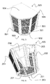
- FIG. 2 shows in detail the filter 105, which comprises, on its six faces, six respective flat filter elements 201, such as activated-carbon cartridges, arranged in an hexagonal pattern to form a side filtering surface.
- filter elements 201 such as activated-carbon cartridges
- the filter 105 comprises a frame 202, in which a plurality of housings have been obtained, each one adapted to receive a respective filter element 201.
- the housings are arranged in the filter around the perimeter of the air inlet 203, thereby defining a side filtering surface by means of the filter elements 201.
- the side filtering surface is complemented by a cover 205 located in a position opposite to the air inlet 203; in this manner, the filter takes a closed configuration which is adapted to effectively filter the air introduced into the air inlet 203.
- the closing surface 205 is preferably hermetically sealed, but it may alternatively be an at least partially filtering surface, provided that it is still adapted to close the structure of the filter 105.
- the filter elements 201 are so positioned as to cause the filter 105 to diverge with respect to the air inlet 203, i.e. the filter diameter at the closing surface 205 is greater than the diameter at the inlet 203.
- the air flow is thus distributed more evenly over the side filtering surface defined by the plurality of filter elements 201.
- Figure 3 illustrates the filter 103 without five of the six filter elements 201.
- the filter elements 201 comprise activated-carbon cartridges which allow filtering any odours from the air collected by the hood, but need to be replaced when no longer effective.
- Figure 3 shows a typical configuration of the filter 103 while replacing the filter elements 201.
- the frame 202 comprises, as aforesaid, a plurality of housings, each adapted to house a respective filter element 201.
- each one of the housings comprises a pair of guides 301a and 301b arranged longitudinally relative to the axis of the filter 105 and adapted to hold the respective filter element 201 in place.
- the frame 202 further comprises, at the base of each pair of guides 301a and 301b, a catch 302 adapted to stop the sliding movement of the filter element 201 at the end of its travel, thus holding it in a firm position.
- the catch 302 comprises a system for retaining the filter elements 201, so as to lock them in position when in use. The user can thus operate the retaining system to decouple the various elements and remove the filter elements for replacement.
- the retaining system is of the type comprising at least one hook/elongated hole pair, which can be pressed or anyway operated by the user in order to disengage the two elements.
- the guides 301a and 301b preferably have a "C" cross-section, with the concave part facing towards the filter element 201 when the latter is housed therein.
- the guides 301a and 301b also form an opening 303 in the upper part of the filter 105, into which the filter element must be inserted during installation, or from which it must be extracted during removal.
- This opening 303 into which the filter element 201 must be inserted is located at that end of the guides which is opposite to the air inlet.
- the closing surface 205 can be removed by the user by using known means such as fastening pins or one or more hinges; the user can thus easily gain access to the filter elements 201 of the filter 105 in order to replace them, by simply lifting the cover 205 (and also, if necessary, by removing or setting aside the aesthetic cover 106 of the hood 101, if the filter has been installed in such a hood).
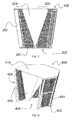
- Figure 4 shows in more detail one of the filter elements 201, which is shaped like an isosceles trapezium, the minor base of which must be inserted into the opening 303 in order to install the element into the filter 105.
- This shape is particularly suitable for insertion into or removal from a housing, and further simplifies replacement by the user.
- the housings obtained in the frame 202 will be wider at the closing surface (i.e. at the top, see figure) than at the air inlet (i.e. at the bottom, see figure).
- each one of the filter elements 201 comprises a plurality of modular filter elements.
- each one of the filter elements 201 comprises one or more layers of filtering material performing different functions, thus being a filter element offering improved capabilities.
- each filter element can be replaced with another element having the same shape and thickness but performing a different function, such as, for example, a perfuming or hygienizing function.
- Modules e.g. white or pigmented, may also be added to the filter elements to indicate the state and level of effectiveness of the filtering material, so that the user can more easily determine when the filter elements need replacing or reconditioning.
- the respective housing will have such a shape and such dimensions as to be suitable for housing the filter element and holding it in place.
- FIG. 4 shows a second embodiment of a filter 505.
- the filter 505 comprises a bearing structure 502 adapted to house five filter elements 501 (which are only partially visible in the drawing) defining a side filtering surface.
- the symmetry of the filter 505 is therefore only partially cylindrical, in that in the bearing structure 502 there is a side face 506 (not shown in the drawing) which is unoccupied by any filter elements and can therefore be closed by a suitable cover or mounted to a flat surface.
- the filter 505 has been conceived, in fact, for use in a "wall-mounted" range hood, i.e. with one side adjacent to a wall.
- the filter 505 comprises an air inlet 503 at the bottom, and a closing element 504 at the top, in a position opposite to the air inlet 503, which closing element 504 can be removed (or opened through suitable hinges) by the user.
- the filter 505 will be installed in a hood in a position similar to that of the filter 105 of Figure 1 ; however, the hood of the filter 505 will be a wall-mounted one, i.e. with a side surface adjacent and secured to a wall.
- Figure 6 shows in detail the filter 105, from which three of the six cartridges 201 have been removed in order to allow observing the inside of the filter 105.
- the filter 105 comprises a bearing structure 202 that creates six housings, wherein each one of these housings is adapted to receive a respective filter element 201, such as an activated-carbon cartridge.
- Activated-carbon cartridges allow filtering odours from the air collected by the hood, and need to be replaced when they lose their effectiveness, e.g. because they have become clogged or have lost their filtering power.
- each housing preferably comprises longitudinal guides, into which the filter elements 201 can be inserted, thus being removable and replaceable by the user.
- each housing preferably comprises a pair of longitudinal guides adapted to hold a respective filter element in place, and a guide access opening for inserting the filter element, said opening preferably facing upwards.
- the bearing structure 202 also comprises retaining means (not shown) that allow fitting the filter elements and replacing them as necessary.
- the bearing structure 202 has a shape that defines an inlet 203 at the lower edge of the side filtering surface, which inlet is in a transverse position relative to the structure with cylindrical symmetry of the filter 105; from the inlet 203, the air can enter the filter 105 to be then filtered by passing through the filter elements 201.
- the filter 105 further comprises a baffle element 204 having a pyramidal shape with a hexagonal base.
- the base of the baffle 204 is mounted on the upper surface 205 of the filter 105, which is closed by a suitable cover.
- the baffle element 204 is positioned centrally with respect to the filter elements 201, i.e. centrally with respect to the bearing structure 202 itself.
- each one of the six side faces of the pyramid of the baffle element 204 faces a respective filter element 201.
- the baffle element 204 can fluid-dynamically interact with the air flow introduced into the filter 105 through the inlet 203, distributing it evenly over the whole filtering surface defined by the filter elements 201.
- the baffle element 204 is made of a sound-absorbing material, such as a known melamine-formaldehyde (MF) foam.
- MF melamine-formaldehyde
- the baffle element has a substantially pyramidal shape, or substantially conical, if it has a circular base.
- the side faces of the baffle element are preferably flat, like those of the baffle element 204, but they may also be curved.
- an alternative embodiment may be conceived wherein the side faces of the baffle element are more or less concave towards the inside of the baffle element itself.
- the leading vertex of the baffle element i.e. the vertex facing towards the inlet 203
- Figure 7 is a sectional view of the filter 105, showing more clearly the arrangement of the baffle element 203 within the bearing structure 202, i.e. central with respect to the side filtering surface defined by the filter elements 201.
- the filter elements 201 are so positioned as to cause the filter 105 to diverge with respect to the inlet 203, i.e. the diameter at the surface 205, which is opposite to the inlet 203 and preferably closed, is greater than the diameter at the inlet 203.
- the air flow is thus distributed more evenly over the side filtering surface defined by the plurality of filter elements 201.
- the surfaces of the filter elements 201 have a divergence angle, calculated with respect to the axis of the filter 105, which is smaller than the divergence angle of the surfaces of the baffle element 204.
- the surfaces of the filter elements 201 preferably have a divergence angle, calculated with respect to the axis of the filter 105, comprised between 0° (straight filter) and 30°, preferably of 15°.
- the surfaces of the baffle elements 204 have a divergence angle, still calculated with respect to the axis of the filter 105, which is greater than the above-described angle, i.e. preferably comprised between 15° and 45°, preferably of 30°.
- the divergence angle of the baffle element is greater by about 15° than the divergence angle of the surfaces of the filter elements 201, so as to create, within the filter 105, an air channel having a decreasing cross-section in order to compensate for the air flow lost through the surfaces of the filter elements 201.
- the filter comprises a baffle element 204 having a divergence angle which is greater than the divergence angle of the filter element 201.
- the different divergence angles contribute to improving the fluid-dynamic characteristics of the filter 105, by reducing the internal load losses and contributing to evenly distributing the air flow over the whole surface of the filter elements 201, thereby improving the effectiveness and life thereof.
- FIG 8 shows a second embodiment of a filter 405.
- the filter 405 comprises a bearing structure 402 adapted to house five filter elements 401 (which are only partially visible in the drawing) defining a side filtering surface.
- the symmetry of the filter 405 is only partially cylindrical, in that in the bearing structure 302 there is a side face 406 which is unoccupied by any filter elements and can be closed by a suitable cover or mounted to a flat surface.
- the filter 405 has been conceived, in fact, for use in a "wall-mounted" range hood, i.e. with one side adjacent to a wall.
- the filter 405 comprises a baffle element 404 positioned centrally with respect to the filter elements 201, wherein the baffle element 404 has a substantially pyramidal shape, but its side faces are inwardly concave.
- Figure 9 is a side view of the filter 404, showing the shape of the baffle element 404, the cross-section of which grows so as to occupy, moving farther from the inlet 403, an increasing volume in the filter 405, and to direct the air flow towards the side filtering surface defined by the filter elements 401.
- the surface 415 is closed, just like the surface 406, which preferably abuts against a wall.
- FIG 10 shows in detail the baffle element 404, which is preferably made of a sound-absorbing material, such as a known melamine-formaldehyde (MF) foam.
- MF melamine-formaldehyde
- the filter 405 will be installed in a hood in a position similar to that of the filter 105 of Figure 1 ; however, the hood of the filter 405 will be a wall-mounted one, i.e. with a side surface adjacent and secured to a wall.
- the baffle element may have alternative shapes, so long as it is still adapted to fluid-dynamically interact with and change the air flow by directing it towards the filtering surface: in this case, further teachings of good fluid-dynamics engineering practice can be applied.
- a filter according to the present invention may be used in hoods of any kind, i.e. without being limited to range hoods, such as industrial or laboratory hoods.
Landscapes
- Engineering & Computer Science (AREA)
- Chemical & Material Sciences (AREA)
- Combustion & Propulsion (AREA)
- Mechanical Engineering (AREA)
- General Engineering & Computer Science (AREA)
- Filtering Of Dispersed Particles In Gases (AREA)
- Ventilation (AREA)
Abstract
Description
- The present invention relates to the field of extraction or recirculating hoods, in particular for treating fumes and odours in household environments, e.g. a range hood.
- The invention relates in particular to an odour filter for a hood, as well as to an associated hood.
- Aspirating and/or filtering devices are known which are to be installed near places where fumes or odours are generated. For example, such aspirating and/or filtering devices are called "hoods" and are typically installed in household environments, such as a kitchen. Within the context of the present invention, the term "fumes" designates an aeriform substance, typically air, contaminated by suspended liquid, solid or ethereal particles. As far as range hoods are concerned, the aspirated fumes typically transport suspended greasy particles and odours generated by food being cooked.
- Some hoods take in fumes from the environment, discharging the aspirated air into a ventilation duct, which then evacuates both fumes and odours out in the open; such hoods are hence referred to as "extraction hoods".
- Some other hoods collect fumes from the environment, filter them, and then reintroduce purified air into the same environment; hoods of this latter type are called "recirculating hoods", and the present invention proves to be especially advantageous for such recirculating hoods.
- One example of a recirculating hood is known from document
WO2009062809A2 , which describes a hood that comprises an air inlet opening connected to a chimney-like discharge element. The discharge element comprises a filter for filtering aspirated fumes/odours; the filter comprises activated-carbon elements for odour elimination, and the filter area is increased in order to ensure the utmost efficiency. - One example of a hood filter is known from document
WO2011064083A1 , which describes a filter comprising an activated-carbon odour filter in which there are a plurality of recesses for improving the filtering performance. - The filter elements, in particular activated-carbon filter elements, used in known hood filters have however a tendency to lose effectiveness after a certain number of working hours, since the adsorbing power of the activated carbon decreases as air keeps flowing through the odour filter, leading to reduced effectiveness of the filter as a whole. The user must therefore take action by replacing or reconditioning the exhausted filter elements, so as to restore the filter to its full effectiveness.
- The Applicant has noticed that the prior art suffers from a particular problem related to difficult replacement of the filter elements. Prior-art filters are, in fact, not easily accessible to the user, and require the user to carry out delicate and uncomfortable operations in order to install and remove the filters and replace the filter elements.
- The hood filters known in the art also suffer from the drawback that they cannot fully exploit their filter elements. As a matter of fact, activated-carbon filters have a tendency to lose effectiveness after a certain number of working hours, since the adsorbing power of the activated carbon decreases as air keeps flowing through the odour filter, leading to reduced effectiveness of the filter as a whole.
- It is the object of the present invention to overcome some of the problems of the prior art. In particular, it is one object of the present invention to provide a hood filter wherein the filter elements can be replaced more easily and quickly.
- It is another object of the present invention to provide a hood filter wherein the filter elements are more effectively exploited.
- It is a further object of the present invention to provide a hood filter wherein the activated-carbon filter elements last longer, the activated-carbon content being equal, thus having a longer life and requiring less maintenance.
- It is yet another object of the present invention to provide a hood filter which improves the hood's performance in terms of filtering capacity and quietness.
- These and other objects of the present invention are achieved through a hood filter and a related hood incorporating the features set out in the appended claims, which are intended to be an integral part of the present description.
- One idea at the basis of the present invention is to provide a hood filter which comprises a plurality of housings, each adapted to receive a respective filter element, wherein said plurality of housings are in side-by-side relation and define a filtering surface, and an air inlet for introducing air the be filtered into said filter. The plurality of housings are arranged in the filter around at least a part of the perimeter of said air inlet, thereby defining a side filtering surface, wherein each one of the housings comprises a pair of longitudinal guides adapted to hold the respective filter element in place, and an opening for inserting the filter element into the pair of guides, the opening being located at the guides' end which is opposite to the air inlet.
- This solution allows to obtain a filter having a simple and compact configuration, wherein the filter elements can be inserted without difficulty into the filter structure and can be replaced quickly.
- Preferably, the filter comprises a closing surface opposite to said air inlet, said closing surface being removable by the user. Thus, the filter structure ensures effective air filtering as well as, when removed, easy access to the filter elements.
- Preferably, the openings of each one of the housings face towards the closing surface. In this manner, when the user opens the filter by removing the closing surface, he/she will gain easy access to the openings for replacing the filter elements.
- Preferably, the side filtering surface is divergent, the width of said housings at the closing surface being greater than the width of the housings at the air inlet. In this manner, the filter can house trapezoidal filter elements with their major base located at the housing opening, thus making the filter elements themselves easier to replace.
- According to a further aspect of the present invention, a hood filter is provided which comprises a plurality of housings, each adapted to receive a respective filter element, wherein said plurality of housings are in side-by-side relation and define a filtering surface, and an inlet for introducing air the be filtered into said filter. The filter further comprises an internal baffle element adapted to fluid-dynamically interact with the air coming from said inlet and direct it towards said filtering surface.
- The baffle element allows to convey the air to be filtered directly towards the filter elements, so as to use the whole surface thereof. This ensures a more effective utilization of each filter element, reducing wear and maintenance thereof. At the same time, the filtering performance of the filter is increased when installed in a hood, since its filtering area is maximized.
- Preferably, the plurality of housings are arranged at least partially with cylindrical symmetry within the filter, thereby defining a side filtering surface, wherein said inlet is in a transverse position at an edge of said side filtering surface, and said baffle element has a pyramidal shape, with its base attached to a surface of said filter opposite to said inlet.
- This solution allows to obtain a filter having a simple and compact configuration, thus limiting the outer dimensions thereof. In addition, the presence of an pyramidal baffle element further improves the fluid-dynamics of the filter by preventing any air recirculation therewithin.
- Preferably, the side filtering surface is divergent, a diameter thereof at said surface opposite to said inlet being greater than the diameter at said inlet.
- Furthermore, the baffle element preferably comprises a plurality of side faces respectively facing towards each one of said filter elements.
- These preferred solutions allow to improve air evacuation from within the filter, as well as to more effectively utilize the whole filtering surface available.
- Preferably, the baffle element is made of sound-absorbing material. In this manner, when the filter is installed in a recirculating hood, it will contribute to dampening the noise generated by the ventilation means associated with the hood, thus reducing the noise produced by the hood as a whole when in operation.
- Preferably, the sound-absorbing material comprises a melamine-formaldehyde foam, which is particularly suited for household use.
- Preferably, the filter elements comprise active carbon on their surfaces, so as to further remove any odours from the filtered air.
- According to the present invention, the filter is to be installed in a hood, preferably by positioning it downstream of the ventilation means.
- The hood comprises an access to a ventilation chimney, whereon the filter is located, with the air inlet in fluidic connection with the chimney and the filter closing surface facing outwards.
- Further objects and advantages of the present invention will become more apparent from the following detailed description and from the annexed drawings.
- Some preferred and advantageous embodiments will now be described by way of non-limiting example with reference to the annexed drawings, wherein:
-
Figure 1 shows an example of embodiment of a hood comprising a filter according to the present invention. -
Figure 2 shows a first embodiment of a filter according to the present invention. -
Figure 3 shows how the filter elements are installed into the filter ofFigure 2 . -
Figure 4 shows in detail one of the filter elements of the filter ofFigure 2 . -
Figure 5 shows a second embodiment of a filter according to the present invention. -
Figure 6 shows a third embodiment of a filter according to the present invention. -
Figure 7 is a sectional view of the filter ofFigure 6 . -
Figure 8 shows a fourth embodiment of a filter according to the present invention. -
Figure 9 is a side view of the filter ofFigure 8 . -
Figure 10 shows in detail the baffle element of the filter ofFigure 8 . - The drawings show different aspects and embodiments of the present invention and, where appropriate, similar structures, components, materials and/or elements in the various drawings are designated by the same reference numerals.
-
Figure 1 shows one example of arange hood 101 of the recirculating type. Thehood 101 comprises a convergingfume collector 102 to be typically positioned above a cooking top, in the case of a range hood. Thefume collector 102 may comprise at its inlet further filter elements (not shown) adapted to filter any greasy particles dragged along by the air, which elements are filters in accordance with the teachings of the prior art. - The
hood 101 is of the "island" type, i.e. it is installed at a distance from the room walls and is accessible on all four sides. - The
hood 101 further comprises air circulating means 103, e.g. a compressor or a fan, adapted to collect air from thefume collector 102 and convey it into thechimney 104. At the outlet of thechimney 104, i.e. at the upper end of thehood 101, there is afilter 105. Thefilter 105 comprises a plurality of filter elements adapted to create a filtering surface, in particular in order to purify the air collected by thehood 101 from any ethereal substances carrying unpleasant odours. Thefilter 105 is masked by theaesthetic appendix 106, which hides it from view to any users in the room where thehood 101 is located. In fact, thehood 101 is of the "recirculating" type; therefore, the air collected by thefume collector 102, once purified, is reintroduced into the same environment. - The
filter 105 comprises a structure adapted to house a plurality of filter elements, preferably flat activated-carbon cartridges. In the example ofFigure 1 , thefilter 105 comprises six flat filter elements, such as cartridges, arranged in an hexagonal pattern to form a side filtering surface. -
Figure 2 shows in detail thefilter 105, which comprises, on its six faces, six respectiveflat filter elements 201, such as activated-carbon cartridges, arranged in an hexagonal pattern to form a side filtering surface. - In particular, the
filter 105 comprises aframe 202, in which a plurality of housings have been obtained, each one adapted to receive arespective filter element 201. - Under the
filter 105, not shown in the drawing, there is an opening that defines anair inlet 203, through which the air to be filtered can enter after having been aspirated by thehood 105 and conveyed into thechimney 104. - The housings are arranged in the filter around the perimeter of the
air inlet 203, thereby defining a side filtering surface by means of thefilter elements 201. The side filtering surface is complemented by acover 205 located in a position opposite to theair inlet 203; in this manner, the filter takes a closed configuration which is adapted to effectively filter the air introduced into theair inlet 203. - The
closing surface 205 is preferably hermetically sealed, but it may alternatively be an at least partially filtering surface, provided that it is still adapted to close the structure of thefilter 105. - The
filter elements 201 are so positioned as to cause thefilter 105 to diverge with respect to theair inlet 203, i.e. the filter diameter at theclosing surface 205 is greater than the diameter at theinlet 203. The air flow is thus distributed more evenly over the side filtering surface defined by the plurality offilter elements 201. -
Figure 3 illustrates thefilter 103 without five of the sixfilter elements 201. Thefilter elements 201 comprise activated-carbon cartridges which allow filtering any odours from the air collected by the hood, but need to be replaced when no longer effective.Figure 3 shows a typical configuration of thefilter 103 while replacing thefilter elements 201. - The
frame 202 comprises, as aforesaid, a plurality of housings, each adapted to house arespective filter element 201. In particular, each one of the housings comprises a pair ofguides filter 105 and adapted to hold therespective filter element 201 in place. - The
frame 202 further comprises, at the base of each pair ofguides catch 302 adapted to stop the sliding movement of thefilter element 201 at the end of its travel, thus holding it in a firm position. Preferably, thecatch 302 comprises a system for retaining thefilter elements 201, so as to lock them in position when in use. The user can thus operate the retaining system to decouple the various elements and remove the filter elements for replacement. Preferably, the retaining system is of the type comprising at least one hook/elongated hole pair, which can be pressed or anyway operated by the user in order to disengage the two elements. - The
guides filter element 201 when the latter is housed therein. - The
guides opening 303 in the upper part of thefilter 105, into which the filter element must be inserted during installation, or from which it must be extracted during removal. Thisopening 303 into which thefilter element 201 must be inserted is located at that end of the guides which is opposite to the air inlet. In addition, theclosing surface 205 can be removed by the user by using known means such as fastening pins or one or more hinges; the user can thus easily gain access to thefilter elements 201 of thefilter 105 in order to replace them, by simply lifting the cover 205 (and also, if necessary, by removing or setting aside theaesthetic cover 106 of thehood 101, if the filter has been installed in such a hood). -
Figure 4 shows in more detail one of thefilter elements 201, which is shaped like an isosceles trapezium, the minor base of which must be inserted into theopening 303 in order to install the element into thefilter 105. This shape is particularly suitable for insertion into or removal from a housing, and further simplifies replacement by the user. - Consequently, the housings obtained in the
frame 202 will be wider at the closing surface (i.e. at the top, see figure) than at the air inlet (i.e. at the bottom, see figure). - Preferably, each one of the
filter elements 201 comprises a plurality of modular filter elements. For example, each one of thefilter elements 201 comprises one or more layers of filtering material performing different functions, thus being a filter element offering improved capabilities. In this way, one can create a filter element which, besides activated-carbon, also comprises other deodorant, antibacterial or perfuming agents and the like. It is also conceivable that each filter element can be replaced with another element having the same shape and thickness but performing a different function, such as, for example, a perfuming or hygienizing function. - Modules, e.g. white or pigmented, may also be added to the filter elements to indicate the state and level of effectiveness of the filtering material, so that the user can more easily determine when the filter elements need replacing or reconditioning.
- It is clear that, whatever the shape and thickness of a filter element, the respective housing will have such a shape and such dimensions as to be suitable for housing the filter element and holding it in place.
-
Figure 4 shows a second embodiment of afilter 505. Thefilter 505 comprises abearing structure 502 adapted to house five filter elements 501 (which are only partially visible in the drawing) defining a side filtering surface. - The symmetry of the
filter 505 is therefore only partially cylindrical, in that in thebearing structure 502 there is a side face 506 (not shown in the drawing) which is unoccupied by any filter elements and can therefore be closed by a suitable cover or mounted to a flat surface. - The
filter 505 has been conceived, in fact, for use in a "wall-mounted" range hood, i.e. with one side adjacent to a wall. - In accordance with the above description, the
filter 505 comprises anair inlet 503 at the bottom, and aclosing element 504 at the top, in a position opposite to theair inlet 503, which closingelement 504 can be removed (or opened through suitable hinges) by the user. - Preferably, the
filter 505 will be installed in a hood in a position similar to that of thefilter 105 ofFigure 1 ; however, the hood of thefilter 505 will be a wall-mounted one, i.e. with a side surface adjacent and secured to a wall. -
Figure 6 shows in detail thefilter 105, from which three of the sixcartridges 201 have been removed in order to allow observing the inside of thefilter 105. - The
filter 105 comprises abearing structure 202 that creates six housings, wherein each one of these housings is adapted to receive arespective filter element 201, such as an activated-carbon cartridge. Activated-carbon cartridges allow filtering odours from the air collected by the hood, and need to be replaced when they lose their effectiveness, e.g. because they have become clogged or have lost their filtering power. - To this end, as aforementioned, the housings preferably comprise longitudinal guides, into which the
filter elements 201 can be inserted, thus being removable and replaceable by the user. In particular, each housing preferably comprises a pair of longitudinal guides adapted to hold a respective filter element in place, and a guide access opening for inserting the filter element, said opening preferably facing upwards. - The bearing
structure 202 also comprises retaining means (not shown) that allow fitting the filter elements and replacing them as necessary. - The bearing
structure 202 has a shape that defines aninlet 203 at the lower edge of the side filtering surface, which inlet is in a transverse position relative to the structure with cylindrical symmetry of thefilter 105; from theinlet 203, the air can enter thefilter 105 to be then filtered by passing through thefilter elements 201. - The
filter 105 further comprises abaffle element 204 having a pyramidal shape with a hexagonal base. The base of thebaffle 204 is mounted on theupper surface 205 of thefilter 105, which is closed by a suitable cover. - The
baffle element 204 is positioned centrally with respect to thefilter elements 201, i.e. centrally with respect to thebearing structure 202 itself. In particular, each one of the six side faces of the pyramid of thebaffle element 204 faces arespective filter element 201. Thebaffle element 204 can fluid-dynamically interact with the air flow introduced into thefilter 105 through theinlet 203, distributing it evenly over the whole filtering surface defined by thefilter elements 201. - Preferably, the
baffle element 204 is made of a sound-absorbing material, such as a known melamine-formaldehyde (MF) foam. In this manner, when thefilter 105 is installed in thehood 101, the sound-absorbing material will contribute to reducing the acoustic noise dispersed in the environment by the air circulating means 103, which would otherwise flow through thechimney 104, thus disturbing the user present in the same environment. Preferably, the baffle element has a substantially pyramidal shape, or substantially conical, if it has a circular base. The side faces of the baffle element are preferably flat, like those of thebaffle element 204, but they may also be curved. - For example, an alternative embodiment may be conceived wherein the side faces of the baffle element are more or less concave towards the inside of the baffle element itself. These variants are selectable on the basis of the fluid-dynamic characteristics verified in different filters, from case to case, in order to improve the performance of the baffle element.
- In an embodiment not shown in the drawing, the leading vertex of the baffle element, i.e. the vertex facing towards the
inlet 203, is prevalently pointed and thin, its angle being preferably smaller than 15°, advantageously of approx. 7°. In this way it is possible to locally improve the fluid-dynamic performance of the baffle element hit by an air flow.Figure 7 is a sectional view of thefilter 105, showing more clearly the arrangement of thebaffle element 203 within the bearingstructure 202, i.e. central with respect to the side filtering surface defined by thefilter elements 201. - The
filter elements 201 are so positioned as to cause thefilter 105 to diverge with respect to theinlet 203, i.e. the diameter at thesurface 205, which is opposite to theinlet 203 and preferably closed, is greater than the diameter at theinlet 203. The air flow is thus distributed more evenly over the side filtering surface defined by the plurality offilter elements 201. - In
Figure 7 one can also appreciate the different angles between the surfaces of thefilter elements 201 and the surfaces of thebaffle element 204. In fact, the surfaces of thefilter elements 201 have a divergence angle, calculated with respect to the axis of thefilter 105, which is smaller than the divergence angle of the surfaces of thebaffle element 204. - In particular, the surfaces of the
filter elements 201 preferably have a divergence angle, calculated with respect to the axis of thefilter 105, comprised between 0° (straight filter) and 30°, preferably of 15°. Instead, the surfaces of thebaffle elements 204 have a divergence angle, still calculated with respect to the axis of thefilter 105, which is greater than the above-described angle, i.e. preferably comprised between 15° and 45°, preferably of 30°. Preferably, the divergence angle of the baffle element is greater by about 15° than the divergence angle of the surfaces of thefilter elements 201, so as to create, within thefilter 105, an air channel having a decreasing cross-section in order to compensate for the air flow lost through the surfaces of thefilter elements 201. - In other words, the filter comprises a
baffle element 204 having a divergence angle which is greater than the divergence angle of thefilter element 201. - The different divergence angles contribute to improving the fluid-dynamic characteristics of the
filter 105, by reducing the internal load losses and contributing to evenly distributing the air flow over the whole surface of thefilter elements 201, thereby improving the effectiveness and life thereof. -
Figure 8 shows a second embodiment of afilter 405. Thefilter 405 comprises abearing structure 402 adapted to house five filter elements 401 (which are only partially visible in the drawing) defining a side filtering surface. - The symmetry of the
filter 405 is only partially cylindrical, in that in thebearing structure 302 there is aside face 406 which is unoccupied by any filter elements and can be closed by a suitable cover or mounted to a flat surface. Thefilter 405 has been conceived, in fact, for use in a "wall-mounted" range hood, i.e. with one side adjacent to a wall. - In accordance with the above description, the
filter 405 comprises abaffle element 404 positioned centrally with respect to thefilter elements 201, wherein thebaffle element 404 has a substantially pyramidal shape, but its side faces are inwardly concave. -
Figure 9 is a side view of thefilter 404, showing the shape of thebaffle element 404, the cross-section of which grows so as to occupy, moving farther from theinlet 403, an increasing volume in thefilter 405, and to direct the air flow towards the side filtering surface defined by thefilter elements 401. Thesurface 415 is closed, just like thesurface 406, which preferably abuts against a wall. -
Figure 10 shows in detail thebaffle element 404, which is preferably made of a sound-absorbing material, such as a known melamine-formaldehyde (MF) foam. - Preferably, the
filter 405 will be installed in a hood in a position similar to that of thefilter 105 ofFigure 1 ; however, the hood of thefilter 405 will be a wall-mounted one, i.e. with a side surface adjacent and secured to a wall. - It is clear that the man skilled in the art may conceive further variants of the present invention, without however departing from the protection scope as defined by the appended claims.
- For example, a plurality of embodiments of the bearing structure are conceivable, which are so designed as to define side-by-side housings defining filtering surfaces having many different shapes. It should be understood, in fact, that the embodiments with five or six filter elements have been described herein by way of non-limiting, explanatory example only: a different number of filter elements may in fact be used, whether smaller than five or greater than six.
- In addition, the baffle element may have alternative shapes, so long as it is still adapted to fluid-dynamically interact with and change the air flow by directing it towards the filtering surface: in this case, further teachings of good fluid-dynamics engineering practice can be applied.
- It is apparent that the present invention, although it has been described herein with reference to a preferred application to recirculating hoods, may likewise be used in combination with extraction hoods, in particular should this be required by specific environmental regulations.
- Furthermore, it should be understood that a filter according to the present invention may be used in hoods of any kind, i.e. without being limited to range hoods, such as industrial or laboratory hoods.
Claims (15)
- A filter (105, 505) configured for use in a hood (101), comprising a plurality of housings, each adapted to receive a respective filter element (201), wherein said plurality of housings are in side-by-side relation and define a filtering surface, and an air inlet (203) for introducing air to be filtered into said filter (105, 505), characterized in that said plurality of housings are arranged in said filter (105, 501) around at least a part of the perimeter of said air inlet (203), thereby defining a side filtering surface, wherein each one of said housings comprises a pair of longitudinal guides (303a, 303b) adapted to hold said respective filter element (201) in place, and an opening (303) for inserting said filter element (201) into said pair of guides (303a, 303b), said opening (303) being located at the end of said guides (303a, 303b) opposite to said air inlet (203).
- A filter according to claim 1, further comprising a closing surface (205) opposite to said air inlet (203), said closing surface (205) being adapted to be removed or opened by a user.
- A filter according to claim 2, wherein said openings (303) of each one of said housings face towards said closing surface (205).
- A filter according to any one of claims 1 to 3, wherein said side filtering surface is divergent, a width of said housings at said closing surface (205) being greater than the width of said housings at said air inlet (203).
- A filter according to any one of claims 1 to 4, wherein said filter elements (201) comprise activated carbon on their surfaces.
- A filter according to claim 5, wherein each one of said filter elements (201) comprises a plurality of filter modules, preferably arranged in layers, which comprise different active ingredients for each layer.
- A filter (105, 405) configured for use in a hood (101), comprising a plurality of housings, each one adapted to receive a respective filter element (201, 401), wherein said housings are in side-by-side relation and define a filtering surface and an inlet (203, 403) for introducing air to be filtered into said filter (105, 405), characterized in that said filter (105, 405) further comprises an internal baffle element (204, 404) adapted to fluid-dynamically interact with air coming from said inlet (203, 403) and direct it towards said filtering surface.
- A filter according to claim 7, wherein said plurality of housings are arranged at least partially with cylindrical symmetry within the filter (105, 405), thereby defining a side filtering surface, wherein said inlet (203, 403) is in a transverse position at an edge of said side filtering surface, and said baffle element (204, 404) has a substantially pyramidal shape, with its base attached to a surface (205, 415) of said filter (105, 405) opposite to said inlet (203, 403).
- A filter according to claim 8, wherein said side filtering surface is divergent, a diameter of said filter (105, 405) at said surface (205, 415) opposite to said inlet (203, 403) being greater than the diameter of said filter (105, 405) at said inlet (203, 403).
- A filter according to claim 8 or 9, wherein said baffle element (204, 404) comprises a plurality of side faces respectively facing towards each one of said filter elements (201, 401).
- A filter according to any one of claims 7 to 10, wherein said baffle element (204, 404) is made of sound-absorbing material, which preferably comprises a melamine-formaldehyde foam.
- A filter according to any one of claims 7 to 11, wherein said filter elements comprise activated carbon on their surfaces.
- A hood (101) comprising a fume collector (102) in fluidic connection with a chimney (104), and air circulating means (103) for collecting air through said fume collector (102) and conveying it into said chimney (104), and further comprising a filter (105) for filtering said air, characterized in that said filter (105) is a filter according to any one of claims 1 to 6 or a filter according to any one of claims 7 to 12.
- A hood according to claim 13, wherein said filter (105) is in fluidic connection with said chimney (104) and is located downstream of said air circulating means (103).
- A hood according to claim 14, wherein said air inlet (203) of said filter (101) is in fluidic connection with said chimney (104), and wherein said filter comprises a closing surface (205) opposite to said air inlet (203) and facing towards the outside of said hood (101).
Applications Claiming Priority (2)
| Application Number | Priority Date | Filing Date | Title |
|---|---|---|---|
| IT001224A ITTO20111224A1 (en) | 2011-12-29 | 2011-12-29 | ODOR FILTER FOR KITCHEN HOOD AND RELATED KITCHEN HOOD |
| IT001223A ITTO20111223A1 (en) | 2011-12-29 | 2011-12-29 | ODOR FILTER FOR KITCHEN HOOD AND RELATED KITCHEN HOOD |
Publications (2)
| Publication Number | Publication Date |
|---|---|
| EP2610556A2 true EP2610556A2 (en) | 2013-07-03 |
| EP2610556A3 EP2610556A3 (en) | 2013-09-11 |
Family
ID=47358582
Family Applications (1)
| Application Number | Title | Priority Date | Filing Date |
|---|---|---|---|
| EP12199492.5A Withdrawn EP2610556A3 (en) | 2011-12-29 | 2012-12-27 | Odour filter for a range hood, and related range hood |
Country Status (1)
| Country | Link |
|---|---|
| EP (1) | EP2610556A3 (en) |
Cited By (5)
| Publication number | Priority date | Publication date | Assignee | Title |
|---|---|---|---|---|
| EP2848869A1 (en) * | 2013-09-13 | 2015-03-18 | BSH Bosch und Siemens Hausgeräte GmbH | Air circulation module for an extractor hood and extractor hood |
| CN104676697A (en) * | 2015-03-09 | 2015-06-03 | 广东美的厨房电器制造有限公司 | Exhaust hood |
| CN108731065A (en) * | 2018-07-14 | 2018-11-02 | 佛山市云米电器科技有限公司 | A kind of kitchen ventilator with noise filtering function guiding subassembly |
| CN117053246A (en) * | 2022-05-05 | 2023-11-14 | 芜湖美的智能厨电制造有限公司 | Nakashima range hood |
| EP4644783A1 (en) * | 2024-05-02 | 2025-11-05 | BSH Hausgeräte GmbH | Circulating air deflector for an extractor hood and extractor hood |
Citations (5)
| Publication number | Priority date | Publication date | Assignee | Title |
|---|---|---|---|---|
| WO2000059606A1 (en) * | 1999-03-31 | 2000-10-12 | Yugen Gaisha Infinity Kenkyusho | Air filter for air conditioner |
| WO2009062809A2 (en) | 2007-11-12 | 2009-05-22 | BSH Bosch und Siemens Hausgeräte GmbH | Extractor device |
| DE102008033792A1 (en) * | 2008-07-18 | 2010-01-21 | BSH Bosch und Siemens Hausgeräte GmbH | Recirculation module and extractor device |
| JP2011020095A (en) * | 2009-07-17 | 2011-02-03 | Nippon Muki Co Ltd | Filter device |
| WO2011064083A1 (en) | 2009-11-30 | 2011-06-03 | BSH Bosch und Siemens Hausgeräte GmbH | Filter element for an extractor hood and extractor hood |
Family Cites Families (7)
| Publication number | Priority date | Publication date | Assignee | Title |
|---|---|---|---|---|
| SE314788B (en) * | 1966-01-13 | 1969-09-15 | Electrolux Ab | |
| DE19838648B4 (en) * | 1998-07-18 | 2004-07-15 | Sirius S.r.l | Hoods system |
| CA2465319A1 (en) * | 2002-08-23 | 2005-04-03 | Access Systems Ltd. | Filter matrix and casings |
| ITRN20030035A1 (en) * | 2003-10-28 | 2005-04-29 | Alfredo Pellegrini | MODULAR FILTER FOR APPLIANCES, IN PARTICULAR FOR FILTER HOODS. |
| EP1705430B1 (en) * | 2005-07-04 | 2016-09-21 | V-Zug AG | Extracting hood with grease filter |
| ITAN20080005A1 (en) * | 2008-02-18 | 2009-08-19 | Ennio Mezzopera | MONOBLOCK STRUCTURE OF A SUCTION HOOD |
| DE102008014283B4 (en) * | 2008-03-06 | 2021-06-10 | Blanco Professional Gmbh + Co Kg | Fume extraction device and such a comprehensive receiving device for at least one food preparation unit |
-
2012
- 2012-12-27 EP EP12199492.5A patent/EP2610556A3/en not_active Withdrawn
Patent Citations (5)
| Publication number | Priority date | Publication date | Assignee | Title |
|---|---|---|---|---|
| WO2000059606A1 (en) * | 1999-03-31 | 2000-10-12 | Yugen Gaisha Infinity Kenkyusho | Air filter for air conditioner |
| WO2009062809A2 (en) | 2007-11-12 | 2009-05-22 | BSH Bosch und Siemens Hausgeräte GmbH | Extractor device |
| DE102008033792A1 (en) * | 2008-07-18 | 2010-01-21 | BSH Bosch und Siemens Hausgeräte GmbH | Recirculation module and extractor device |
| JP2011020095A (en) * | 2009-07-17 | 2011-02-03 | Nippon Muki Co Ltd | Filter device |
| WO2011064083A1 (en) | 2009-11-30 | 2011-06-03 | BSH Bosch und Siemens Hausgeräte GmbH | Filter element for an extractor hood and extractor hood |
Cited By (5)
| Publication number | Priority date | Publication date | Assignee | Title |
|---|---|---|---|---|
| EP2848869A1 (en) * | 2013-09-13 | 2015-03-18 | BSH Bosch und Siemens Hausgeräte GmbH | Air circulation module for an extractor hood and extractor hood |
| CN104676697A (en) * | 2015-03-09 | 2015-06-03 | 广东美的厨房电器制造有限公司 | Exhaust hood |
| CN108731065A (en) * | 2018-07-14 | 2018-11-02 | 佛山市云米电器科技有限公司 | A kind of kitchen ventilator with noise filtering function guiding subassembly |
| CN117053246A (en) * | 2022-05-05 | 2023-11-14 | 芜湖美的智能厨电制造有限公司 | Nakashima range hood |
| EP4644783A1 (en) * | 2024-05-02 | 2025-11-05 | BSH Hausgeräte GmbH | Circulating air deflector for an extractor hood and extractor hood |
Also Published As
| Publication number | Publication date |
|---|---|
| EP2610556A3 (en) | 2013-09-11 |
Similar Documents
| Publication | Publication Date | Title |
|---|---|---|
| US11885505B2 (en) | Filter device and fume extraction device comprising filter device | |
| EP3380791B1 (en) | A hood for domestic use | |
| EP2610555B1 (en) | Hood with a grease filter | |
| KR20180047424A (en) | Dust collector comprising cylindrical filter | |
| US20140056764A1 (en) | Odour control unit | |
| WO2015179670A9 (en) | Multi-stage hood filter system | |
| EP3163175B1 (en) | Filtering hood with filters facing the impeller | |
| KR20110012038U (en) | Kitchen Range Hood Unit with Auxiliary Intake | |
| EP2839220B1 (en) | Range hood comprising an odour filter | |
| JP3849065B2 (en) | Range hood fan with built-in filter | |
| KR102657265B1 (en) | Ventilation system for kitchen hood in which air curtain is formed to prevent the spread of contaminated air and ventilation by introduction of clean outdoor air is possible | |
| CN118856391B (en) | Air duct structure, range hood and range hood integrated machine | |
| CN210485817U (en) | Graded module oil smoke purification device | |
| EP2966363A1 (en) | Improved filtering hood | |
| US8529669B2 (en) | Method and apparatus for collecting grease from a rooftop exhaust fan | |
| EP4067754B1 (en) | Air treatment device | |
| JP2009127890A (en) | Range hood | |
| KR102149319B1 (en) | Grease Filter | |
| KR20220094974A (en) | Range hood | |
| KR100903752B1 (en) | Indoor ventilation | |
| KR102816200B1 (en) | Hood detachable auxiliary device | |
| CN201959694U (en) | Oil fume filter | |
| KR102793289B1 (en) | Kitchen hood for home use | |
| EP2839218A1 (en) | Grease filter for a range hood | |
| KR200383643Y1 (en) | A hood of gas range |
Legal Events
| Date | Code | Title | Description |
|---|---|---|---|
| PUAI | Public reference made under article 153(3) epc to a published international application that has entered the european phase |
Free format text: ORIGINAL CODE: 0009012 |
|
| AK | Designated contracting states |
Kind code of ref document: A2 Designated state(s): AL AT BE BG CH CY CZ DE DK EE ES FI FR GB GR HR HU IE IS IT LI LT LU LV MC MK MT NL NO PL PT RO RS SE SI SK SM TR |
|
| AX | Request for extension of the european patent |
Extension state: BA ME |
|
| PUAL | Search report despatched |
Free format text: ORIGINAL CODE: 0009013 |
|
| AK | Designated contracting states |
Kind code of ref document: A3 Designated state(s): AL AT BE BG CH CY CZ DE DK EE ES FI FR GB GR HR HU IE IS IT LI LT LU LV MC MK MT NL NO PL PT RO RS SE SI SK SM TR |
|
| AX | Request for extension of the european patent |
Extension state: BA ME |
|
| RIC1 | Information provided on ipc code assigned before grant |
Ipc: F24C 15/20 20060101AFI20130808BHEP |
|
| 17P | Request for examination filed |
Effective date: 20140310 |
|
| RBV | Designated contracting states (corrected) |
Designated state(s): AL AT BE BG CH CY CZ DE DK EE ES FI FR GB GR HR HU IE IS IT LI LT LU LV MC MK MT NL NO PL PT RO RS SE SI SK SM TR |
|
| 17Q | First examination report despatched |
Effective date: 20160411 |
|
| STAA | Information on the status of an ep patent application or granted ep patent |
Free format text: STATUS: THE APPLICATION IS DEEMED TO BE WITHDRAWN |
|
| 18D | Application deemed to be withdrawn |
Effective date: 20160823 |