EP2610488A1 - Wind turbine device and method for constructing tower for blade wheel - Google Patents
Wind turbine device and method for constructing tower for blade wheel Download PDFInfo
- Publication number
- EP2610488A1 EP2610488A1 EP10787984.3A EP10787984A EP2610488A1 EP 2610488 A1 EP2610488 A1 EP 2610488A1 EP 10787984 A EP10787984 A EP 10787984A EP 2610488 A1 EP2610488 A1 EP 2610488A1
- Authority
- EP
- European Patent Office
- Prior art keywords
- tower
- wind turbine
- double
- tube structure
- outer cylinder
- Prior art date
- Legal status (The legal status is an assumption and is not a legal conclusion. Google has not performed a legal analysis and makes no representation as to the accuracy of the status listed.)
- Withdrawn
Links
- 241000736911 Turritella communis Species 0.000 claims abstract description 41
- 230000005404 monopole Effects 0.000 claims abstract description 6
- 239000004567 concrete Substances 0.000 claims description 37
- 238000010276 construction Methods 0.000 claims description 29
- 230000004048 modification Effects 0.000 description 7
- 238000012986 modification Methods 0.000 description 7
- 238000005304 joining Methods 0.000 description 2
- 229910000831 Steel Inorganic materials 0.000 description 1
- 230000004075 alteration Effects 0.000 description 1
- 238000004873 anchoring Methods 0.000 description 1
- 230000005540 biological transmission Effects 0.000 description 1
- 230000006835 compression Effects 0.000 description 1
- 238000007906 compression Methods 0.000 description 1
- 230000000694 effects Effects 0.000 description 1
- 238000004519 manufacturing process Methods 0.000 description 1
- 239000011150 reinforced concrete Substances 0.000 description 1
- 239000010959 steel Substances 0.000 description 1
- 238000005728 strengthening Methods 0.000 description 1
- 238000003466 welding Methods 0.000 description 1
Images



Classifications
-
- E—FIXED CONSTRUCTIONS
- E04—BUILDING
- E04H—BUILDINGS OR LIKE STRUCTURES FOR PARTICULAR PURPOSES; SWIMMING OR SPLASH BATHS OR POOLS; MASTS; FENCING; TENTS OR CANOPIES, IN GENERAL
- E04H12/00—Towers; Masts or poles; Chimney stacks; Water-towers; Methods of erecting such structures
-
- E—FIXED CONSTRUCTIONS
- E04—BUILDING
- E04H—BUILDINGS OR LIKE STRUCTURES FOR PARTICULAR PURPOSES; SWIMMING OR SPLASH BATHS OR POOLS; MASTS; FENCING; TENTS OR CANOPIES, IN GENERAL
- E04H12/00—Towers; Masts or poles; Chimney stacks; Water-towers; Methods of erecting such structures
- E04H12/18—Towers; Masts or poles; Chimney stacks; Water-towers; Methods of erecting such structures movable or with movable sections, e.g. rotatable or telescopic
- E04H12/185—Towers; Masts or poles; Chimney stacks; Water-towers; Methods of erecting such structures movable or with movable sections, e.g. rotatable or telescopic with identical elements
-
- E—FIXED CONSTRUCTIONS
- E04—BUILDING
- E04H—BUILDINGS OR LIKE STRUCTURES FOR PARTICULAR PURPOSES; SWIMMING OR SPLASH BATHS OR POOLS; MASTS; FENCING; TENTS OR CANOPIES, IN GENERAL
- E04H12/00—Towers; Masts or poles; Chimney stacks; Water-towers; Methods of erecting such structures
- E04H12/02—Structures made of specified materials
- E04H12/08—Structures made of specified materials of metal
-
- E—FIXED CONSTRUCTIONS
- E04—BUILDING
- E04H—BUILDINGS OR LIKE STRUCTURES FOR PARTICULAR PURPOSES; SWIMMING OR SPLASH BATHS OR POOLS; MASTS; FENCING; TENTS OR CANOPIES, IN GENERAL
- E04H12/00—Towers; Masts or poles; Chimney stacks; Water-towers; Methods of erecting such structures
- E04H12/02—Structures made of specified materials
- E04H12/12—Structures made of specified materials of concrete or other stone-like material, with or without internal or external reinforcements, e.g. with metal coverings, with permanent form elements
-
- F—MECHANICAL ENGINEERING; LIGHTING; HEATING; WEAPONS; BLASTING
- F03—MACHINES OR ENGINES FOR LIQUIDS; WIND, SPRING, OR WEIGHT MOTORS; PRODUCING MECHANICAL POWER OR A REACTIVE PROPULSIVE THRUST, NOT OTHERWISE PROVIDED FOR
- F03D—WIND MOTORS
- F03D13/00—Assembly, mounting or commissioning of wind motors; Arrangements specially adapted for transporting wind motor components
- F03D13/10—Assembly of wind motors; Arrangements for erecting wind motors
-
- F—MECHANICAL ENGINEERING; LIGHTING; HEATING; WEAPONS; BLASTING
- F03—MACHINES OR ENGINES FOR LIQUIDS; WIND, SPRING, OR WEIGHT MOTORS; PRODUCING MECHANICAL POWER OR A REACTIVE PROPULSIVE THRUST, NOT OTHERWISE PROVIDED FOR
- F03D—WIND MOTORS
- F03D13/00—Assembly, mounting or commissioning of wind motors; Arrangements specially adapted for transporting wind motor components
- F03D13/20—Arrangements for mounting or supporting wind motors; Masts or towers for wind motors
-
- F—MECHANICAL ENGINEERING; LIGHTING; HEATING; WEAPONS; BLASTING
- F03—MACHINES OR ENGINES FOR LIQUIDS; WIND, SPRING, OR WEIGHT MOTORS; PRODUCING MECHANICAL POWER OR A REACTIVE PROPULSIVE THRUST, NOT OTHERWISE PROVIDED FOR
- F03D—WIND MOTORS
- F03D13/00—Assembly, mounting or commissioning of wind motors; Arrangements specially adapted for transporting wind motor components
- F03D13/20—Arrangements for mounting or supporting wind motors; Masts or towers for wind motors
- F03D13/22—Foundations specially adapted for wind motors
-
- F—MECHANICAL ENGINEERING; LIGHTING; HEATING; WEAPONS; BLASTING
- F03—MACHINES OR ENGINES FOR LIQUIDS; WIND, SPRING, OR WEIGHT MOTORS; PRODUCING MECHANICAL POWER OR A REACTIVE PROPULSIVE THRUST, NOT OTHERWISE PROVIDED FOR
- F03D—WIND MOTORS
- F03D9/00—Adaptations of wind motors for special use; Combinations of wind motors with apparatus driven thereby; Wind motors specially adapted for installation in particular locations
- F03D9/20—Wind motors characterised by the driven apparatus
- F03D9/25—Wind motors characterised by the driven apparatus the apparatus being an electrical generator
-
- F—MECHANICAL ENGINEERING; LIGHTING; HEATING; WEAPONS; BLASTING
- F05—INDEXING SCHEMES RELATING TO ENGINES OR PUMPS IN VARIOUS SUBCLASSES OF CLASSES F01-F04
- F05B—INDEXING SCHEME RELATING TO WIND, SPRING, WEIGHT, INERTIA OR LIKE MOTORS, TO MACHINES OR ENGINES FOR LIQUIDS COVERED BY SUBCLASSES F03B, F03D AND F03G
- F05B2240/00—Components
- F05B2240/90—Mounting on supporting structures or systems
- F05B2240/91—Mounting on supporting structures or systems on a stationary structure
- F05B2240/912—Mounting on supporting structures or systems on a stationary structure on a tower
-
- Y—GENERAL TAGGING OF NEW TECHNOLOGICAL DEVELOPMENTS; GENERAL TAGGING OF CROSS-SECTIONAL TECHNOLOGIES SPANNING OVER SEVERAL SECTIONS OF THE IPC; TECHNICAL SUBJECTS COVERED BY FORMER USPC CROSS-REFERENCE ART COLLECTIONS [XRACs] AND DIGESTS
- Y02—TECHNOLOGIES OR APPLICATIONS FOR MITIGATION OR ADAPTATION AGAINST CLIMATE CHANGE
- Y02E—REDUCTION OF GREENHOUSE GAS [GHG] EMISSIONS, RELATED TO ENERGY GENERATION, TRANSMISSION OR DISTRIBUTION
- Y02E10/00—Energy generation through renewable energy sources
- Y02E10/70—Wind energy
- Y02E10/72—Wind turbines with rotation axis in wind direction
-
- Y—GENERAL TAGGING OF NEW TECHNOLOGICAL DEVELOPMENTS; GENERAL TAGGING OF CROSS-SECTIONAL TECHNOLOGIES SPANNING OVER SEVERAL SECTIONS OF THE IPC; TECHNICAL SUBJECTS COVERED BY FORMER USPC CROSS-REFERENCE ART COLLECTIONS [XRACs] AND DIGESTS
- Y02—TECHNOLOGIES OR APPLICATIONS FOR MITIGATION OR ADAPTATION AGAINST CLIMATE CHANGE
- Y02E—REDUCTION OF GREENHOUSE GAS [GHG] EMISSIONS, RELATED TO ENERGY GENERATION, TRANSMISSION OR DISTRIBUTION
- Y02E10/00—Energy generation through renewable energy sources
- Y02E10/70—Wind energy
- Y02E10/728—Onshore wind turbines
Definitions
- the present invention relates to a wind turbine generator having a nacelle installed at a top portion of a wind turbine tower to generate power, and to a construction method for a wind turbine tower.
- a wind turbine generator is a device in which a hub equipped with turbine blades rotates upon receiving wind power, and a generator that is driven by, for example, accelerating this rotation with a gearbox, generates power.
- the above-described hub is attached at an end portion of a nacelle, which is installed on top of a wind turbine tower (hereinafter referred to as "tower") in a manner that allows yawing, and is supported so as to be rotatable in a lateral direction about a substantially horizontal rotation axis.
- a steel-monopole type tower using a cylindrical tower shell is often employed in the above-described wind turbine tower, having a structure in which a base plate provided at the bottom end of the tower shell is secured to a steel-reinforced concrete base with anchoring bolts, or a structure in which the shell is directly embedded into the base.
- the above-described tower shell employed herein is a steel plate that is bent into a cylindrical form and welded together at edge portions thereof.
- Patent Literature mentioned below discloses a base structure that is applied to a pile type tower structure, like a tower structure for a wind turbine generator, for example.
- concrete at the joining portions between the base and the tower structure has to set before proceeding to the next step.
- the tower of a typical wind turbine generator is fabricated at a factory as a plurality of parts, which are divided in the length direction, etc., and the individual parts are transported to a construction site for assembly. Therefore, transportation limits established for public roads, etc. for transporting individual parts from the factory to a construction site restrict increases in the size and height of the tower.
- the present invention has been conceived in light of the above-described situation, and an object thereof is to provide a wind turbine generator, having a tower structure that can cope with increases in the size and height thereof while avoiding the restrictions of transportation limits, as well as a construction method for a wind turbine tower.
- a wind turbine generator of the present invention is a wind turbine generator in which a nacelle is installed at a top portion of a monopole type wind turbine tower, in which cylindrical tower shells are connected together, to generate power, wherein the wind turbine tower is provided with a double-tube structure at least at the bottom end of the tower.
- the wind turbine tower is provided with the double-tube structure at least at the bottom end of the tower, it is possible to cope with increases in the height and the diameter by increasing the rigidity of the wind turbine tower.
- the double-tube structure preferably has the tower shell serving as an inner cylinder, an outer cylinder is provided so as to surround the outer circumference of the inner cylinder, and the inner cylinder and the outer cylinder are connected together.
- the outer cylinder may be shaped like a circular truncated cone, which is connected at a top end thereof with an outer circumferential surface of the inner cylinder, and the diameter thereof gradually increases toward a bottom end thereof.
- the outer cylinder can be divided into a plurality of sections in the circumferential direction and can be transported separately from the inner cylinder. That is, when the diameter of the wind turbine tower is increased, it is desirable that the outer cylinder and the inner cylinder should be structured as separate pieces, and a more preferable structure of the outer cylinder is one that allows transportation to the construction site as a plurality of sections divided in the circumferential direction, enabling assembly at the construction site.
- the double-tube structure is preferably provided with a concrete-filled layer in which a space between the inner cylinder and the outer cylinder is filled with concrete, and, accordingly, the rigidity can be further increased.
- a protruding portion that protrudes into the concrete-filled layer from wall surfaces of the inner cylinder and the outer cylinder be provided.
- a construction method for the wind turbine tower of the wind turbine generator of the present invention is a construction method for a wind turbine tower of a wind turbine generator in which a nacelle is installed at a top portion of a monopole type wind turbine tower, in which cylindrical tower shells are connected together, to generate power, the wind turbine tower being provided with a double-tube structure in which a space between an inner cylinder and an outer cylinder is filled with concrete at least at the bottom end of the tower, wherein a tower-shell connecting step, in which the tower shells are connected upward on the double-tube structure, is performed in parallel with a concrete pouring step, in which the double-tube structure is filled with concrete.
- the rigidity of the wind turbine tower can be increased with substantially the same construction period as with a conventional structure.
- the rigidity of the wind turbine tower can be increased, it becomes possible to cope with increases in the size and height thereof, while avoiding the restrictions of transportation limits.
- the construction method for the wind turbine tower of the wind turbine generator of the present invention even with a wind turbine tower whose rigidity can be further increased by performing the concrete pouring step, construction with substantially the same construction period as with the conventional construction is possible.
- a wind turbine generator 1 shown in Fig. 10 includes a wind turbine tower (hereinafter, referred to as "tower") 2 erected on a base B, a nacelle 3 that is installed at the top end of the tower 2, and a hub 4, which is provided at the front end of the nacelle 3 while being supported so as to be rotatable in a lateral direction about a substantially horizontal rotation axis.
- tower wind turbine tower
- nacelle 3 that is installed at the top end of the tower 2
- hub 4 which is provided at the front end of the nacelle 3 while being supported so as to be rotatable in a lateral direction about a substantially horizontal rotation axis.
- a plurality of (for example, three) turbine blades 5 are attached to the hub 4 in a radiating pattern around the rotation axis thereof. Accordingly, the force of wind striking the turbine blades 5 in the rotation axis direction of the hub 4 is converted to motive power that rotates the hub 4 about the rotation axis thereof.
- the tower 2 of the above-described wind turbine generator 1 is a monopole type tower in which a plurality of cylindrical tower shells are connected, and, for example, as shown in Figs. 1 and 2 , a double-tube structure 20 is provided at least at the bottom end of the tower.
- the double-tube structure 20 has a tower shell 2a of the tower 2 serving as an inner cylinder, and an outer cylinder 21 is provided so as to surround the outer circumference of the tower shell 2a, and, by providing connecting members such as ribs 22 and flanges 23, etc. at appropriate locations, the tower shell 2a and the outer cylinder 21 are integrally connected together by welding, bolting, or the like.
- the tower shell 2a at the bottom-most level and the outer cylinder 21 are secured to a common base plate 10 in the example configuration shown in Fig. 2 , it is desirable, especially when the tower diameter is large, to have a structure in which independent base plates are employed in a separate-piece structure, and the outer cylinder 21 is mounted at the construction site.
- the thus-configured double-tube structure 20 is secured to the base B by inserting anchor bolts 12 into bolt holes 11, a number of which are provided in the base plate 10, and by tightening nuts 13 on the anchor bolts 12.
- the bolt holes 11 are provided on both the inside and outside of the tower shells 2a and the outer cylinder 21 in the illustrated example configuration, it is not limited thereto.
- reference sign 2b denotes flanges for connecting the tower shells 2a
- reference sign 14 denotes a grouting layer.
- the above-described double-tube structure 20 enables transmission of force by being connected with the outer cylinder 21, which is larger in diameter than the tower shell 2a, at the bottom end of the tower 2, the cross-sectional area of the double-tube structure 20 is increased, and the tower shell 2a and the outer cylinder 21 cope with the applied force as an integrated strengthening member, thereby increasing the rigidity of the tower 2.
- Increasing the rigidity of the tower 2 in this way makes it easier to increase the height and diameter of the tower 2 as the output power of the wind turbine generator 1 is increased.
- the increased rigidity of the tower 2 makes it possible to reduce the diameter and the plate thickness of the tower shell 2a, by amounts corresponding to the increased rigidity due to the the double-tube structure 20.
- the outer cylinder 21 when the outer cylinder 21 is configured as the separate-piece structure which is mounted on site, the required rigidity can be ensured by manufacturing the tower shells 2a to be transported from the factory to the construction site within the restrictions of transportation limits and by finally mounting the outer cylinder 21 at the construction site.
- a bolted structure in which, for example, as in an outer cylinder 21' shown in Fig. 7 , the outer cylinder 21 is divided into a plurality of sections (four sections in the illustrated example) in the circumferential direction of the cylindrical shape, which are transported to the construction site, and the flanges 21a are joined with nuts and bolts 24.
- a welded structure may be employed, in which edges of members at corner portions of a rectangular cross-section are bonded, on site, with welded portions 25 to form a cylindrical shape.
- the outer cylinder 21, having a larger diameter than the tower shell 2a can readily avoid the restrictions of the transportation limits; therefore, the above-described double-tube structure 20 can increase the rigidity in accordance with increase in diameter of the tower 2.
- outer cylinder 21 has been described as having a cylindrical shape with a diameter larger than the tower shell 2a, which has a cylindrical shape, for example, an outer cylinder 21A with a rectangular cross-section shown in Fig. 5 , as a first modification, or an outer cylinder 21B with a hexagonal cross-section shown in Fig. 6 , as a second modification, is permissible, and the cross-sectional shape thereof is not particularly limited.
- the tower rigidity can be increased to an equivalent level as compared with a configuration having the same cross-sectional shape in the height direction.
- the above-described double-tube structure 20 should be provided with a concrete-filled layer 30 wherein a space between the tower shell 2a, serving as the inner cylinder, and the outer cylinder 21 is filled with concrete. That is, because the double-tube structure specifically has increased strength against compression stress due to the properties of concrete, the double-tube structure 20A provided with the concrete-filled layer 30 has an even greater rigidity as compared with the double-tube structure 20 in which a space therein is left hollow without filling it with concrete.
- the above-described concrete layer 30 is preferably provided with protruding portions like stud dowels 31 that protrude into the concrete-filled layer 30 from an outer-wall surface of the tower shell 2a and an inner-wall surface of the outer cylinder 21. Because such stud dowels 31 integrate the tower shell 2a and the outer cylinder 21, with the concrete-filled layer 30 firmly joining them, a further increase in rigidity becomes possible. Note that the concrete-filled layer 30 as described above can also be formed between the tower shell 2a and the outer cylinders 21A to 21c in the above-described modifications.
- the tower 2 of the wind turbine generator 1 provided with the above-described double-tube structure 20A is constructed by a construction method described below. That is, in the construction method for the wind turbine tower provided with the double-tube structure 20A in which the concrete-filled layer 30 is formed, at least at the bottom end of the tower, by filling the space between the tower shells 2a and the outer cylinder 21 with concrete, a tower-shell connecting step, in which the tower shells 2a are connected upward on the double-tube structure 20A, is performed in parallel with a concrete pouring step, in which the double-tube structure 20A is filled with concrete.
- the wind turbine tower construction method described above is possible because the tower-shell connecting step is not affected by setting of the concrete poured in the concrete-filled layer 30.
- the tower-shell connecting step in which the tower shells 2a are connected upward on the double-tube structure 20A, can be performed in parallel with and is affected little by the concrete pouring step for the double-tube structure 20A, which requires time for concrete to set, the construction period is almost never extended. Therefore, with substantially the same construction period as with a conventional structure without the the double-tube structure 20A, the tower 2 with increased rigidity can be constructed with a structure provided with the the double-tube structure 20A, which achieves superior, increased rigidity.
- the rigidity of the tower 2 can be increased by the double-tube structure 20 or 20A, it is possible to cope with an increase in the size of the wind turbine generator 1 and an increase in the height of the tower 2, while avoiding the restrictions of transportation limits.
- the wind turbine tower construction method of the above-described embodiment even with the tower 2 provided with the double-tube structure 20A which makes it possible to further increase the rigidity by performing the concrete pouring step, construction is possible with substantially the same construction period as with the conventional construction. Note that the present invention is not limited to the above-described embodiment, and appropriate alterations are permissible within a range that does not depart from the gist of the present invention.
Landscapes
- Engineering & Computer Science (AREA)
- Architecture (AREA)
- Life Sciences & Earth Sciences (AREA)
- Chemical & Material Sciences (AREA)
- Structural Engineering (AREA)
- Civil Engineering (AREA)
- Sustainable Energy (AREA)
- General Engineering & Computer Science (AREA)
- Mechanical Engineering (AREA)
- Combustion & Propulsion (AREA)
- Sustainable Development (AREA)
- Materials Engineering (AREA)
- Wood Science & Technology (AREA)
- Wind Motors (AREA)
Abstract
Provided is a wind turbine generator having a tower structure that can cope with increases in the size and height thereof while avoiding the restrictions of transportation limits. In a wind turbine generator in which a nacelle is installed at a top portion of a monopole type wind turbine tower, in which tower shells (2a) having circular cylindrical shapes are connected together, to generate power, the tower (2) is provided with a double-tube structure (20) at least at the bottom end of the tower.
Description
- The present invention relates to a wind turbine generator having a nacelle installed at a top portion of a wind turbine tower to generate power, and to a construction method for a wind turbine tower.
- A wind turbine generator is a device in which a hub equipped with turbine blades rotates upon receiving wind power, and a generator that is driven by, for example, accelerating this rotation with a gearbox, generates power.
The above-described hub is attached at an end portion of a nacelle, which is installed on top of a wind turbine tower (hereinafter referred to as "tower") in a manner that allows yawing, and is supported so as to be rotatable in a lateral direction about a substantially horizontal rotation axis. - Generally, a steel-monopole type tower using a cylindrical tower shell is often employed in the above-described wind turbine tower, having a structure in which a base plate provided at the bottom end of the tower shell is secured to a steel-reinforced concrete base with anchoring bolts, or a structure in which the shell is directly embedded into the base. Note that the above-described tower shell employed herein is a steel plate that is bent into a cylindrical form and welded together at edge portions thereof.
- The Patent Literature mentioned below discloses a base structure that is applied to a pile type tower structure, like a tower structure for a wind turbine generator, for example. In this case, concrete at the joining portions between the base and the tower structure has to set before proceeding to the next step.
-
- {PTL 1}
U.S. Patent Application Publication No. 2006/0185279 {Summary of Invention} - In recent years, because wind turbine generators tend to have increased output power, it has become necessary to increase the size and height of the tower. In general, such increases in the size and height of the tower result in increased tower diameter and increased plate thickness thereof.
On the other hand, the tower of a typical wind turbine generator is fabricated at a factory as a plurality of parts, which are divided in the length direction, etc., and the individual parts are transported to a construction site for assembly. Therefore, transportation limits established for public roads, etc. for transporting individual parts from the factory to a construction site restrict increases in the size and height of the tower. - Accordingly, there is a natural limit to increasing the size and height of the tower due to the above-described restrictions of transportation limits.
The present invention has been conceived in light of the above-described situation, and an object thereof is to provide a wind turbine generator, having a tower structure that can cope with increases in the size and height thereof while avoiding the restrictions of transportation limits, as well as a construction method for a wind turbine tower. - In order to solve the above-described problems, the present invention employs the following solutions.
A wind turbine generator of the present invention is a wind turbine generator in which a nacelle is installed at a top portion of a monopole type wind turbine tower, in which cylindrical tower shells are connected together, to generate power, wherein the wind turbine tower is provided with a double-tube structure at least at the bottom end of the tower. - With the wind turbine generator described above, because the wind turbine tower is provided with the double-tube structure at least at the bottom end of the tower, it is possible to cope with increases in the height and the diameter by increasing the rigidity of the wind turbine tower.
- In this case, the the double-tube structure preferably has the tower shell serving as an inner cylinder, an outer cylinder is provided so as to surround the outer circumference of the inner cylinder, and the inner cylinder and the outer cylinder are connected together.
In addition, the outer cylinder may be shaped like a circular truncated cone, which is connected at a top end thereof with an outer circumferential surface of the inner cylinder, and the diameter thereof gradually increases toward a bottom end thereof. - In the above-described invention, preferably, the outer cylinder can be divided into a plurality of sections in the circumferential direction and can be transported separately from the inner cylinder.
That is, when the diameter of the wind turbine tower is increased, it is desirable that the outer cylinder and the inner cylinder should be structured as separate pieces, and a more preferable structure of the outer cylinder is one that allows transportation to the construction site as a plurality of sections divided in the circumferential direction, enabling assembly at the construction site. - In the above-described invention, the double-tube structure is preferably provided with a concrete-filled layer in which a space between the inner cylinder and the outer cylinder is filled with concrete, and, accordingly, the rigidity can be further increased.
In this case, it is preferable that a protruding portion that protrudes into the concrete-filled layer from wall surfaces of the inner cylinder and the outer cylinder be provided. - A construction method for the wind turbine tower of the wind turbine generator of the present invention is a construction method for a wind turbine tower of a wind turbine generator in which a nacelle is installed at a top portion of a monopole type wind turbine tower, in which cylindrical tower shells are connected together, to generate power, the wind turbine tower being provided with a double-tube structure in which a space between an inner cylinder and an outer cylinder is filled with concrete at least at the bottom end of the tower, wherein a tower-shell connecting step, in which the tower shells are connected upward on the double-tube structure, is performed in parallel with a concrete pouring step, in which the double-tube structure is filled with concrete.
- With the construction method for the wind turbine tower of the wind turbine generator described above, because the tower-shell connecting step, in which the tower shells are connected upward on the double-tube structure, is performed in parallel with the concrete pouring step, in which the double-tube structure is filled with concrete, the rigidity of the wind turbine tower can be increased with substantially the same construction period as with a conventional structure.
- With the wind turbine generator of the present invention, because the rigidity of the wind turbine tower can be increased, it becomes possible to cope with increases in the size and height thereof, while avoiding the restrictions of transportation limits.
In addition, with the construction method for the wind turbine tower of the wind turbine generator of the present invention, even with a wind turbine tower whose rigidity can be further increased by performing the concrete pouring step, construction with substantially the same construction period as with the conventional construction is possible. -
- {
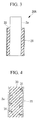
Fig. 1} Fig. 1 is a schematic perspective view showing an embodiment of a double-tube structure in a wind turbine tower for a wind turbine generator according to the present invention. - {
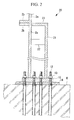
Fig. 2} Fig. 2 is a longitudinal sectional view showing the double-tube structure inFig. 1 . - {
Fig. 3} Fig. 3 is a longitudinal sectional view showing a double-tube structure in which a concrete-filled layer is formed. - {
Fig. 4} Fig. 4 is a partial enlarged sectional view of the double-tube structure equipped with protruding portions that protrude into the concrete-filled layer. - {
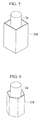
Fig. 5} Fig. 5 is a schematic perspective view of a first modification of the double-tube structure, wherein an outer cylinder has a rectangular cross-section. - {
Fig. 6} Fig. 6 is a schematic perspective view of a second modification of the double-tube structure, wherein the outer cylinder has a hexagonal cross-section. - {
Fig. 7} Fig. 7 is a sectional view showing a bolt joint structure as an example of a divided structure of the outer cylinder. - {
Fig. 8} Fig. 8 is a sectional view showing a welded structure as an example of the divided structure of the outer cylinder. - {
Fig. 9} Fig. 9 is a schematic perspective view of a third modification of the double-tube structure, wherein the outer cylinder is shaped like a circular truncated cone. - {
Fig. 10} Fig. 10 is a side view showing an outline of the wind turbine generator. - A wind turbine generator and a construction method for a wind turbine tower according to an embodiment of the present invention will be described below on the basis of the drawings.
A wind turbine generator 1 shown inFig. 10 includes a wind turbine tower (hereinafter, referred to as "tower") 2 erected on a base B, a nacelle 3 that is installed at the top end of thetower 2, and a hub 4, which is provided at the front end of the nacelle 3 while being supported so as to be rotatable in a lateral direction about a substantially horizontal rotation axis. - A plurality of (for example, three)
turbine blades 5 are attached to the hub 4 in a radiating pattern around the rotation axis thereof. Accordingly, the force of wind striking theturbine blades 5 in the rotation axis direction of the hub 4 is converted to motive power that rotates the hub 4 about the rotation axis thereof. - The
tower 2 of the above-described wind turbine generator 1 is a monopole type tower in which a plurality of cylindrical tower shells are connected, and, for example, as shown inFigs. 1 and2 , a double-tube structure 20 is provided at least at the bottom end of the tower.
The double-tube structure 20 has atower shell 2a of thetower 2 serving as an inner cylinder, and anouter cylinder 21 is provided so as to surround the outer circumference of thetower shell 2a, and, by providing connecting members such asribs 22 andflanges 23, etc. at appropriate locations, thetower shell 2a and theouter cylinder 21 are integrally connected together by welding, bolting, or the like. - Although the
tower shell 2a at the bottom-most level and theouter cylinder 21 are secured to acommon base plate 10 in the example configuration shown inFig. 2 , it is desirable, especially when the tower diameter is large, to have a structure in which independent base plates are employed in a separate-piece structure, and theouter cylinder 21 is mounted at the construction site.
The thus-configured double-tube structure 20 is secured to the base B by insertinganchor bolts 12 intobolt holes 11, a number of which are provided in thebase plate 10, and by tighteningnuts 13 on theanchor bolts 12. Although thebolt holes 11 are provided on both the inside and outside of thetower shells 2a and theouter cylinder 21 in the illustrated example configuration, it is not limited thereto. Note that, in the figures,reference sign 2b denotes flanges for connecting thetower shells 2a, andreference sign 14 denotes a grouting layer. - Because the above-described double-
tube structure 20 enables transmission of force by being connected with theouter cylinder 21, which is larger in diameter than thetower shell 2a, at the bottom end of thetower 2, the cross-sectional area of the double-tube structure 20 is increased, and thetower shell 2a and theouter cylinder 21 cope with the applied force as an integrated strengthening member, thereby increasing the rigidity of thetower 2.
Increasing the rigidity of thetower 2 in this way makes it easier to increase the height and diameter of thetower 2 as the output power of the wind turbine generator 1 is increased. In addition, the increased rigidity of thetower 2 makes it possible to reduce the diameter and the plate thickness of thetower shell 2a, by amounts corresponding to the increased rigidity due to the the double-tube structure 20. - Specifically, when the
outer cylinder 21 is configured as the separate-piece structure which is mounted on site, the required rigidity can be ensured by manufacturing thetower shells 2a to be transported from the factory to the construction site within the restrictions of transportation limits and by finally mounting theouter cylinder 21 at the construction site.
In this case it is desirable to have a bolted structure in which, for example, as in an outer cylinder 21' shown inFig. 7 , theouter cylinder 21 is divided into a plurality of sections (four sections in the illustrated example) in the circumferential direction of the cylindrical shape, which are transported to the construction site, and theflanges 21a are joined with nuts andbolts 24. Alternatively, for example, as in theouter cylinder 21" shown inFig. 8 , a welded structure may be employed, in which edges of members at corner portions of a rectangular cross-section are bonded, on site, withwelded portions 25 to form a cylindrical shape. - That is, by having a structure that is divided in the circumferential direction to allow assembly on site, the
outer cylinder 21, having a larger diameter than thetower shell 2a, can readily avoid the restrictions of the transportation limits; therefore, the above-described double-tube structure 20 can increase the rigidity in accordance with increase in diameter of thetower 2. - Incidentally, although the above-described
outer cylinder 21 has been described as having a cylindrical shape with a diameter larger than thetower shell 2a, which has a cylindrical shape, for example, anouter cylinder 21A with a rectangular cross-section shown inFig. 5 , as a first modification, or anouter cylinder 21B with a hexagonal cross-section shown inFig. 6 , as a second modification, is permissible, and the cross-sectional shape thereof is not particularly limited.
In addition, anouter cylinder 21c of a third modification shown inFig. 9 is shaped like a circular truncated cone, wherein the top end thereof is connected to an outer circumferential surface of thetower shell 2a, which serves as an inner cylinder, and the diameter thereof gradually increases toward the bottom end, which is the base B side. In theouter cylinder 21c having such a circular truncated cone shape, even with a low height, the tower rigidity can be increased to an equivalent level as compared with a configuration having the same cross-sectional shape in the height direction. - It is desirable that, for example, as in a double-
tube structure 20A shownFig. 3 , the above-described double-tube structure 20 should be provided with a concrete-filledlayer 30 wherein a space between thetower shell 2a, serving as the inner cylinder, and theouter cylinder 21 is filled with concrete. That is, because the double-tube structure specifically has increased strength against compression stress due to the properties of concrete, the double-tube structure 20A provided with the concrete-filledlayer 30 has an even greater rigidity as compared with the double-tube structure 20 in which a space therein is left hollow without filling it with concrete. - As shown in
Fig. 4 , for example, the above-describedconcrete layer 30 is preferably provided with protruding portions like stud dowels 31 that protrude into the concrete-filledlayer 30 from an outer-wall surface of thetower shell 2a and an inner-wall surface of theouter cylinder 21. Because such stud dowels 31 integrate thetower shell 2a and theouter cylinder 21, with the concrete-filledlayer 30 firmly joining them, a further increase in rigidity becomes possible.
Note that the concrete-filledlayer 30 as described above can also be formed between thetower shell 2a and theouter cylinders 21A to 21c in the above-described modifications. - The
tower 2 of the wind turbine generator 1 provided with the above-described double-tube structure 20A is constructed by a construction method described below.
That is, in the construction method for the wind turbine tower provided with the double-tube structure 20A in which the concrete-filledlayer 30 is formed, at least at the bottom end of the tower, by filling the space between thetower shells 2a and theouter cylinder 21 with concrete, a tower-shell connecting step, in which thetower shells 2a are connected upward on the double-tube structure 20A, is performed in parallel with a concrete pouring step, in which the double-tube structure 20A is filled with concrete. - The wind turbine tower construction method described above is possible because the tower-shell connecting step is not affected by setting of the concrete poured in the concrete-filled
layer 30.
As a result, because the tower-shell connecting step, in which thetower shells 2a are connected upward on the double-tube structure 20A, can be performed in parallel with and is affected little by the concrete pouring step for the double-tube structure 20A, which requires time for concrete to set, the construction period is almost never extended. Therefore, with substantially the same construction period as with a conventional structure without the the double-tube structure 20A, thetower 2 with increased rigidity can be constructed with a structure provided with the the double-tube structure 20A, which achieves superior, increased rigidity. - In this way, with the wind turbine generator 1 of the above-described embodiment, because the rigidity of the
tower 2 can be increased by the double-tube structure tower 2, while avoiding the restrictions of transportation limits.
In addition, by employing the wind turbine tower construction method of the above-described embodiment, even with thetower 2 provided with the double-tube structure 20A which makes it possible to further increase the rigidity by performing the concrete pouring step, construction is possible with substantially the same construction period as with the conventional construction.
Note that the present invention is not limited to the above-described embodiment, and appropriate alterations are permissible within a range that does not depart from the gist of the present invention. -
{Reference Signs List} 1: wind turbine generator 2: wind turbine tower (tower) 2a: tower shell (inner cylinder) 3: nacelle 10: base plate 20, 20A: the double- tube structure 21, 21A to 21c: outer cylinder 30: concrete-filled layer 31: stud dowel (protruding portion)
Claims (7)
- A wind turbine generator in which a nacelle is installed at a top portion of a monopole type wind turbine tower, in which cylindrical tower shells are connected together, to generate power,
wherein the wind turbine tower is provided with a double-tube structure at least at the bottom end of the tower. - A wind turbine generator according to Claim 1, wherein the double-tube structure has the tower shell serving as an inner cylinder, an outer cylinder is provided so as to surround the outer circumference of the inner cylinder, and the inner cylinder and the outer cylinder are connected together.
- A wind turbine generator according to Claim 2, wherein the outer cylinder is shaped like a circular truncated cone, which is connected at a top end thereof with an outer circumferential surface of the inner cylinder, and the diameter thereof gradually increases toward a bottom end thereof.
- A wind turbine generator according to Claim 2, wherein the outer cylinder can be divided into a plurality of sections in the circumferential direction and can be transported separately from the inner cylinder.
- A wind turbine generator according to Claim 2, wherein the double-tube structure is provided with a concrete-filled layer in which a space between the inner cylinder and the outer cylinder is filled with concrete.
- A wind turbine generator according to Claim 5, further comprising a protruding portion that protrudes into the concrete-filled layer from wall surfaces of the inner cylinder and the outer cylinder.
- A construction method for a wind turbine tower of a wind turbine generator in which a nacelle is installed at a top portion of a monopole type wind turbine tower, in which cylindrical tower shells are connected together, to generate power,
the wind turbine tower being provided with a double-tube structure in which a space between an inner cylinder and an outer cylinder is filled with concrete at least at the bottom end of the tower,
wherein a tower-shell connecting step, in which the tower shells are connected upward on the double-tube structure, is performed in parallel with a concrete pouring step, in which the double-tube structure is filled with concrete.
Applications Claiming Priority (1)
| Application Number | Priority Date | Filing Date | Title |
|---|---|---|---|
| PCT/JP2010/064231 WO2012025985A1 (en) | 2010-08-24 | 2010-08-24 | Wind turbine device and method for constructing tower for blade wheel |
Publications (1)
| Publication Number | Publication Date |
|---|---|
| EP2610488A1 true EP2610488A1 (en) | 2013-07-03 |
Family
ID=44141366
Family Applications (1)
| Application Number | Title | Priority Date | Filing Date |
|---|---|---|---|
| EP10787984.3A Withdrawn EP2610488A1 (en) | 2010-08-24 | 2010-08-24 | Wind turbine device and method for constructing tower for blade wheel |
Country Status (9)
| Country | Link |
|---|---|
| US (1) | US20110138731A1 (en) |
| EP (1) | EP2610488A1 (en) |
| JP (1) | JP5314708B2 (en) |
| KR (1) | KR20120073154A (en) |
| CN (1) | CN102713277A (en) |
| AU (1) | AU2010249278A1 (en) |
| BR (1) | BRPI1004557A2 (en) |
| CA (1) | CA2722226A1 (en) |
| WO (1) | WO2012025985A1 (en) |
Families Citing this family (16)
| Publication number | Priority date | Publication date | Assignee | Title |
|---|---|---|---|---|
| DE102012024412A1 (en) * | 2012-12-14 | 2014-06-18 | Senvion Se | Method for anchoring a foundation structure and foundation structure |
| CN103114568A (en) * | 2013-03-17 | 2013-05-22 | 浙江海洋学院 | Building supporting equipment applied to oceanographic engineering |
| US10519685B2 (en) * | 2014-02-28 | 2019-12-31 | University Of Maine System Board Of Trustees | Hybrid concrete-composite tower for a wind turbine and method of manufacturing |
| DE102015209661A1 (en) * | 2015-05-27 | 2016-12-01 | Rwe Innogy Gmbh | Method for founding a tower construction as well as onshore tower construction |
| DE102015216444A1 (en) * | 2015-08-27 | 2017-03-02 | Wobben Properties Gmbh | Wind turbine |
| KR101742752B1 (en) * | 2016-03-14 | 2017-06-01 | 한국해양과학기술원 | Hybrid wind power tower combined with steel tower and dsct tower |
| DE102016206755A1 (en) * | 2016-04-21 | 2017-10-26 | Thyssenkrupp Ag | Transition body for a tower of a wind turbine, tower with these and method for its construction |
| CN105888986B (en) * | 2016-06-21 | 2019-02-19 | 湖南科技大学 | A kind of fan tower tube assembly, tower tube and tower tube installation method |
| US20210148339A1 (en) * | 2017-05-26 | 2021-05-20 | Envision Energy (Jiangsu) Co., Ltd. | A Cone Shaped Pin for Tower Wall Attachment |
| CN108798189B (en) * | 2018-04-20 | 2020-04-14 | 合肥海银杆塔有限公司 | Novel high-strength cement tower |
| CN108868285A (en) * | 2018-05-07 | 2018-11-23 | 南京宁风能源科技有限公司 | A kind of wind-powered electricity generation place anemometer tower suitable for different terrain |
| ES2951288T3 (en) * | 2018-06-14 | 2023-10-19 | Vestas Wind Sys As | Wind turbine power train connection |
| CN113070987B (en) * | 2019-01-04 | 2023-01-24 | 上海电气风电集团股份有限公司 | Molds for making wind power concrete towers and wind power concrete towers |
| CN110080272A (en) * | 2019-04-25 | 2019-08-02 | 上海交通大学 | Offshore wind farm single-pile foundation and offshore wind farm device suitable for greater coasting area |
| CN111765042A (en) * | 2020-07-15 | 2020-10-13 | 刘亚民 | Wind wheel with tower barrel as shaft |
| CN117514629A (en) * | 2022-07-29 | 2024-02-06 | 广东金风科技有限公司 | Wind turbine tower and wind turbine generator including the wind turbine tower |
Family Cites Families (34)
| Publication number | Priority date | Publication date | Assignee | Title |
|---|---|---|---|---|
| US3942296A (en) * | 1974-10-07 | 1976-03-09 | International Telephone And Telegraph Corporation | Tubular pole with base connection |
| US4242851A (en) * | 1979-04-16 | 1981-01-06 | Pohlman Joe C | Pole construction |
| JPS55138566A (en) * | 1979-04-17 | 1980-10-29 | Shiroyama Seisakusho Kk | Method of reinforcing prestressed concrete pole |
| EP0191016A1 (en) * | 1984-08-15 | 1986-08-20 | Utilitech, Inc. | Portable apparatus for and method of pole reinforcement |
| US6176062B1 (en) * | 1996-02-05 | 2001-01-23 | Osmose Wood Preserving, Inc. | Pole protector |
| US6705058B1 (en) * | 1999-02-12 | 2004-03-16 | Newmark International Inc. | Multiple-part pole |
| ES2160539B1 (en) * | 2000-02-10 | 2003-04-01 | Jimenez Belinchon S A | APPLICABLE CAMOUFLAGE PROVISION ON TOWERS SUPPORT OF ANTENNAS OF TECHNELOMUNICATIONS OR SIMILAR. |
| JP2002061564A (en) * | 2000-08-22 | 2002-02-28 | Mitsubishi Heavy Ind Ltd | Windmill for wind power generation |
| JP3648146B2 (en) * | 2000-10-16 | 2005-05-18 | 株式会社ピーエス三菱 | Wind power tower |
| US6470645B1 (en) * | 2000-11-09 | 2002-10-29 | Beaird Industries, Inc. | Method for making and erecting a wind tower |
| JP4590810B2 (en) * | 2001-09-19 | 2010-12-01 | パナソニック電工株式会社 | Pole with collapse prevention function |
| DE10152550A1 (en) * | 2001-10-24 | 2003-05-08 | Gen Electric | module |
| DK200200178A (en) * | 2002-02-06 | 2003-08-07 | Vestas Wind Sys As | Wind turbine tower suspension means |
| WO2004099609A1 (en) * | 2003-05-09 | 2004-11-18 | Vestas Wind Systems A/S | Wind turbine tower suspension arrangement |
| US20040020160A1 (en) * | 2002-08-01 | 2004-02-05 | Durocher Russell A. | Concrete forming system |
| JP4355949B2 (en) * | 2002-10-01 | 2009-11-04 | ゼネラル・エレクトリック・カンパニイ | Modular kit for wind turbine tower |
| DE60317372T2 (en) * | 2003-03-19 | 2008-08-21 | Vestas Wind Systems A/S | LARGE DESIGNED TOWERS FOR WIND POWER PLANTS AND METHOD FOR BUILDING SUCH TOWERS |
| EP1616066B1 (en) * | 2003-04-09 | 2010-04-07 | General Electric Company | Method for generating a substantially uninterrupted connection of the peripheral wall portions of two adjacent tubular segments |
| DE10330963A1 (en) | 2003-07-08 | 2005-01-27 | Repower Systems Ag | Foundation for buildings |
| US7116282B2 (en) * | 2003-10-14 | 2006-10-03 | John Trankina | Tower reinforcement |
| EP1561883B1 (en) * | 2004-02-04 | 2007-10-10 | Corus Staal BV | Tower for a wind turbine, prefabricated metal wall part for use in tower for a wind turbine and method for constructing a tower for a wind turbine |
| US7464512B1 (en) * | 2004-03-10 | 2008-12-16 | Perina Mark J | Hollow structural member |
| DE102004017006B4 (en) * | 2004-04-02 | 2012-03-29 | Aloys Wobben | Method of erecting a tower |
| CN2714970Y (en) * | 2004-06-23 | 2005-08-03 | 上海同济高科技发展有限公司 | Double-layer steel cylinder |
| ES1058539Y (en) * | 2004-10-11 | 2005-04-01 | Inneo21 S L | PERFECTED MODULAR TOWER STRUCTURE FOR WIND TURBINES AND OTHER APPLICATIONS. |
| US20060185729A1 (en) * | 2005-02-18 | 2006-08-24 | Ingram Thomas L | Double-walled flexible dispenser sump connection system |
| ES2246734B1 (en) * | 2005-04-21 | 2007-04-16 | STRUCTURAL CONCRETE & STEEL, S.L. | PREFABRICATED MODULAR TOWER. |
| US8051627B2 (en) * | 2006-04-30 | 2011-11-08 | General Electric Company | Tower adapter, method of producing a tower foundation and tower foundation |
| ES2326010B2 (en) * | 2006-08-16 | 2011-02-18 | Inneo21, S.L. | STRUCTURE AND PROCEDURE FOR ASSEMBLING CONCRETE TOWERS FOR WIND TURBINES. |
| WO2009056898A1 (en) * | 2007-11-02 | 2009-05-07 | Alejandro Cortina-Cordero | Post-tensioned concrete tower for wind turbines |
| DE102008010660B3 (en) * | 2008-02-22 | 2009-09-24 | Repower Systems Ag | Construction of a wind turbine |
| PL2727813T3 (en) * | 2008-04-23 | 2018-07-31 | Principle Power, Inc. | Column-stabilized offshore platform with water-entrapment plates and asymmetric mooring system for support of offshore wind turbines |
| CN201187421Y (en) * | 2008-07-03 | 2009-01-28 | 浙江华仪风能开发有限公司 | Tower frame of wind generating set |
| US8106528B2 (en) * | 2009-07-08 | 2012-01-31 | Houly Co., Ltd. | Horizontal axis wind turbine with rotatable tower |
-
2010
- 2010-08-24 CN CN2010800027485A patent/CN102713277A/en active Pending
- 2010-08-24 CA CA2722226A patent/CA2722226A1/en not_active Abandoned
- 2010-08-24 BR BRPI1004557A patent/BRPI1004557A2/en not_active IP Right Cessation
- 2010-08-24 KR KR1020117007104A patent/KR20120073154A/en not_active Ceased
- 2010-08-24 EP EP10787984.3A patent/EP2610488A1/en not_active Withdrawn
- 2010-08-24 AU AU2010249278A patent/AU2010249278A1/en not_active Abandoned
- 2010-08-24 WO PCT/JP2010/064231 patent/WO2012025985A1/en not_active Ceased
- 2010-08-24 JP JP2010547776A patent/JP5314708B2/en not_active Expired - Fee Related
- 2010-12-09 US US12/964,089 patent/US20110138731A1/en not_active Abandoned
Non-Patent Citations (1)
| Title |
|---|
| See references of WO2012025985A1 * |
Also Published As
| Publication number | Publication date |
|---|---|
| CN102713277A (en) | 2012-10-03 |
| CA2722226A1 (en) | 2012-02-24 |
| WO2012025985A1 (en) | 2012-03-01 |
| AU2010249278A1 (en) | 2012-03-08 |
| US20110138731A1 (en) | 2011-06-16 |
| JPWO2012025985A1 (en) | 2013-10-28 |
| KR20120073154A (en) | 2012-07-04 |
| BRPI1004557A2 (en) | 2016-03-22 |
| JP5314708B2 (en) | 2013-10-16 |
Similar Documents
| Publication | Publication Date | Title |
|---|---|---|
| US20110138731A1 (en) | Wind turbine generator and construction method for wind turbine tower | |
| JP5148689B2 (en) | Monopole tower and wind turbine generator equipped with monopole tower | |
| CN111456909B (en) | Central tube component, central tube having the same, and tower tube foundation | |
| US7805895B2 (en) | Foundation for enabling anchoring of a wind turbine tower thereto by means of replaceable through-bolts | |
| EP1947328B1 (en) | Joining device for hybrid wind turbine towers | |
| US10822764B2 (en) | Method of connecting a tower to a foundation | |
| US20160265514A1 (en) | Support device and methods for improving and constructing a support device | |
| US20180320400A1 (en) | Joining device of a metal segment to a concrete segment in a hybrid hollow tower | |
| EP3290692B1 (en) | Wind-turbine tower, wind turbine, and method of assembling wind-turbine tower | |
| CN210766856U (en) | Prefabricated spliced center cylinder and tower cylinder foundation with same | |
| JP2010236224A (en) | Basic structure of tower structure | |
| JP2021042590A (en) | Hybrid structure | |
| KR20150076789A (en) | Transition pieces of offshore wind turbines and whole structure of wind turbines having it | |
| CN218816765U (en) | Support structure for wind turbines | |
| JP2020186522A (en) | Foundation structure of tower-like structure | |
| JP2024165024A (en) | Seismic control structure for underwater tower-type structures | |
| TW201124618A (en) | Single-column type tower post and wind-powered electricity generating device having the same. |
Legal Events
| Date | Code | Title | Description |
|---|---|---|---|
| PUAI | Public reference made under article 153(3) epc to a published international application that has entered the european phase |
Free format text: ORIGINAL CODE: 0009012 |
|
| STAA | Information on the status of an ep patent application or granted ep patent |
Free format text: STATUS: THE APPLICATION HAS BEEN WITHDRAWN |
|
| 17P | Request for examination filed |
Effective date: 20101209 |
|
| AK | Designated contracting states |
Kind code of ref document: A1 Designated state(s): AL AT BE BG CH CY CZ DE DK EE ES FI FR GB GR HR HU IE IS IT LI LT LU LV MC MK MT NL NO PL PT RO SE SI SK SM TR |
|
| 18W | Application withdrawn |
Effective date: 20130621 |