EP2610079B1 - Tire - Google Patents
Tire Download PDFInfo
- Publication number
- EP2610079B1 EP2610079B1 EP11820055.9A EP11820055A EP2610079B1 EP 2610079 B1 EP2610079 B1 EP 2610079B1 EP 11820055 A EP11820055 A EP 11820055A EP 2610079 B1 EP2610079 B1 EP 2610079B1
- Authority
- EP
- European Patent Office
- Prior art keywords
- tire
- protrusion
- tread
- portions
- land
- Prior art date
- Legal status (The legal status is an assumption and is not a legal conclusion. Google has not performed a legal analysis and makes no representation as to the accuracy of the status listed.)
- Not-in-force
Links
Images


Classifications
-
- B—PERFORMING OPERATIONS; TRANSPORTING
- B60—VEHICLES IN GENERAL
- B60C—VEHICLE TYRES; TYRE INFLATION; TYRE CHANGING; CONNECTING VALVES TO INFLATABLE ELASTIC BODIES IN GENERAL; DEVICES OR ARRANGEMENTS RELATED TO TYRES
- B60C13/00—Tyre sidewalls; Protecting, decorating, marking, or the like, thereof
- B60C13/02—Arrangement of grooves or ribs
-
- B—PERFORMING OPERATIONS; TRANSPORTING
- B60—VEHICLES IN GENERAL
- B60C—VEHICLE TYRES; TYRE INFLATION; TYRE CHANGING; CONNECTING VALVES TO INFLATABLE ELASTIC BODIES IN GENERAL; DEVICES OR ARRANGEMENTS RELATED TO TYRES
- B60C11/00—Tyre tread bands; Tread patterns; Anti-skid inserts
- B60C11/01—Shape of the shoulders between tread and sidewall, e.g. rounded, stepped or cantilevered
-
- B—PERFORMING OPERATIONS; TRANSPORTING
- B60—VEHICLES IN GENERAL
- B60C—VEHICLE TYRES; TYRE INFLATION; TYRE CHANGING; CONNECTING VALVES TO INFLATABLE ELASTIC BODIES IN GENERAL; DEVICES OR ARRANGEMENTS RELATED TO TYRES
- B60C11/00—Tyre tread bands; Tread patterns; Anti-skid inserts
- B60C11/03—Tread patterns
- B60C11/11—Tread patterns in which the raised area of the pattern consists only of isolated elements, e.g. blocks
-
- B—PERFORMING OPERATIONS; TRANSPORTING
- B60—VEHICLES IN GENERAL
- B60C—VEHICLE TYRES; TYRE INFLATION; TYRE CHANGING; CONNECTING VALVES TO INFLATABLE ELASTIC BODIES IN GENERAL; DEVICES OR ARRANGEMENTS RELATED TO TYRES
- B60C11/00—Tyre tread bands; Tread patterns; Anti-skid inserts
- B60C11/03—Tread patterns
- B60C11/13—Tread patterns characterised by the groove cross-section, e.g. for buttressing or preventing stone-trapping
- B60C11/1307—Tread patterns characterised by the groove cross-section, e.g. for buttressing or preventing stone-trapping with special features of the groove walls
- B60C2011/1338—Tread patterns characterised by the groove cross-section, e.g. for buttressing or preventing stone-trapping with special features of the groove walls comprising protrusions
Landscapes
- Engineering & Computer Science (AREA)
- Mechanical Engineering (AREA)
- Tires In General (AREA)
Description
- The present invention relates to a tire including: a bead portion; a sidewall portion continuously extended from the bead portion; a tread portion configured to come into contact with a road surface; and a buttress portion extending inward in a tire radial direction from a tread end portion and continuously extended from the sidewall portion, the tread end portion being an outer end portion of the tread portion in a tread width direction.
- Rubber materials having viscoelastic properties exhibit hysteresis behavior. Thus, a tire's tread portion generates heat as it deforms and contracts repeatedly through rotation. Increase in the amount of the rubber material constituting the tread portion leads to increase in the hysteresis loss due to the bending deformation and shearing deformation in rotation of the tire. Accordingly, a tire with a thicker tread portion is more likely to experience temperature increase.
- Specifically, large-sized tires designed for large-sized vehicles for use in mines, construction sites, etc. contain a large amount of rubber material used therein and, in addition, are used with heavy loads thereon on rough road surfaces under harsh traction conditions. Since tires deform and contact repeatedly, large tires are characterized as being more likely to generate heat. If a tire's temperature becomes high during travel, that temperature can lead, for example, to separation of the rubber material forming the tread portion from the belt layer, which in turn shortens the tire replacement cycle.
- In this respect, methods have heretofore been known in which sub-grooves extending in the tread width direction are formed in the tread portion to reduce the amount of the rubber material being a source of the heat generation, and also to increase the surface area of the tread portion to thereby facilitate heat dissipation of the tread portion (
Patent Document 1, for example). - Attention is drawn to the disclosure of
JP 2007-030547 JP 2009-268809 - Patent Document 1: Japanese Patent Application Publication No.
2003-205706 Fig. 1 and the like - However, the conventional tires have the following problem. The heat dissipation can be facilitated by forming lateral grooves (sub-grooves) crossing the tire circumferential direction and thus increasing the groove area. Increasing the groove area, however, leads to reduction in the rigidity of the tread portion and reduction in the wear resistance thereof. As described above, there is a trade-off between the heat dissipation performance of a tire and the rigidity of the tire. Hence, there is a limitation in securing the heat dissipation performance by increasing the groove area.
- Therefore, an object of the present invention is to provide a tire capable of securely achieving improved heat dissipation performance without impairing the rigidity and wear resistance of its tread portion.
- To solve the above problem, one aspect of the present invention provides a tire according to
claim 1. - In the tire according to the first aspect of the invention, the first protrusions are formed in the buttress. Thus, an airflow around the tire is disturbed by the protrusions and taken into the corresponding lateral groove portions, thereby increasing the flow volume of air flowing inside the lateral grooves. As a result, the heat transfer coefficient inside the lateral grooves is improved. Accordingly, the temperature of the land portions can be reduced. Further, the temperature of the tread portion can be lowered.
- A second aspect of the present provides a tire according to
claim 2. - In the tire according to the second aspect of the present invention, the protrusion is formed on the side surface of each of the land portions that crosses the width direction of the tread portion. Thus, air flowing over the surface of the tire hits the protrusion and gets disturbed. Since the protrusion is located near each of the lateral grooves formed between the land portions, an airflow around the tire is disturbed by the protrusion and thereby taken into the lateral groove.
- The air gap is formed between the most protruded portion of the protrusion from the side surface in the tread width direction and the side surface of the adjacent land portion in the width direction of the tread portion crossing the width direction of the tread portion. Thus, air taken into the circumferential groove portion flows into the lateral groove portion. As a result, the heat transfer coefficient inside the lateral groove is improved. Accordingly, the temperature of the land portions can be reduced. Further, the temperature of the tread portion can be lowered.
- Each protrusion may be formed near the lateral or lateral groove portion located on one side with respect to a center of the corresponding land portion in the circumferential direction, and the other side of the side surface with respect to the center of the corresponding land portion in the circumferential direction may be almost flat and smooth.
- Each protrusion may have a rectangular shape extending in the tire radial direction, and p < 0.4W may be satisfied, where p is a length, within a section of the land portion defined by the lateral grooves or lateral groove portions, from an end portion of the side surface in the tire circumferential direction to a protrusion center line set at a center of the corresponding protrusion in the tire circumferential direction and extending in a lengthwise direction of the corresponding protrusion, and W is a pitch of the lateral grooves or lateral groove portions between the land portions.
- An angle θ between the protrusion center line and a tire normal line may satisfy |θ| ≤ 60°.
- The tire normal line may coincide with the lengthwise direction of the rectangular shape.
- 2.00 ≤ W/Lw may be satisfied, where Lw is a length of each protrusion in the tread width direction, and W is a pitch of the lateral grooves or lateral groove portions.
- 0 ≤ Lr < WB/2 may be satisfied, where WB is a length of each of the land portions in the tire circumferential direction, and Lr is a length of each protrusion in the tire circumferential direction.
- 0.10 ≤ Lh/H may be satisfied, where Lh is a length of each protrusion in the tire radial direction, and H is a length of each of the land portions in the tire radial direction from a groove bottom of each of the lateral grooves or lateral groove portions defining the land portions.
- The lateral grooves or lateral groove portions may be tilted with respect to a tread-width-direction line extending in the tread width direction, and each protrusion may be provided in an end-portion region including an end portion of the corresponding land portion on a side where an angle between a side surface of the land portion extending in the tire circumferential direction and a wall surface of the corresponding lateral groove or lateral groove portion is an acute angle.
- [DELETED]
-
- [
Fig. 1] Fig. 1 is a perspective view of a pneumatic tire according to an embodiment, which is not according to the invention, but which is useful for understanding the invention. - [
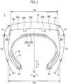
Fig. 2] Fig. 2 is a cross-sectional view of the pneumatic tire according to the embodiment taken along the tread width direction and the tire radial direction. - [
Fig. 3] Fig. 3 is an enlarged perspective view of an enlarged version of the tread of the pneumatic tire. - [
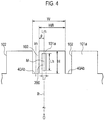
Fig. 4] Fig. 4 is a side view seen in the direction of an arrow A inFig. 3 . - [
Fig. 5] Fig. 5 is a plan view seen in the direction of an arrow B inFig. 3 . Portion (a) ofFig. 5 is a schematic view describing airflows generated when thepneumatic tire 1 is rotated in a rotation direction R1, while Portion (b) ofFig. 5 is a schematic view describing airflows generated when thepneumatic tire 1 is rotated in a rotation direction R2. - [
Fig. 6 ] Portion (a) ofFig. 6 is a schematic view describing airflows generated when apneumatic tire 2, which is not according to the invention, but which is useful for understanding the invention, is rotated in the rotation direction R1, while Portion (b) ofFig. 6 is a schematic view describing airflows generated when thepneumatic tire 2 is rotated in the rotation direction R2. - [
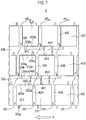
Fig. 7] Fig. 7 is a plan view of a pneumatic tire, which is according to the present invention, seen in a direction perpendicular to its tread surface, the pneumatic tire being shown as a modification of the embodiment. - [
Fig. 8] Fig. 8 is a view describing modifications of the shape of protrusions of the embodiment. - Embodiments of a
pneumatic tire 1 will be described with reference to the drawings. Specifically, description will be given of (1) Inner Configuration of Pneumatic Tire, (2) Description of Protrusions, (3) Operations and Effects, (4) Modifications, and (5) Other Embodiments. - Note that, in the following description of the drawings, the same or similar reference numerals denote the same or similar portions. However, it should be noted that the drawings are schematic, and dimensional ratios and the like are different from the actual ones. Therefore, specific dimensions and the like should be determined in consideration of the following description. Moreover, the drawings also include portions having different dimensional relationships and ratios from each other.
-
Fig. 1 is a perspective view of thepneumatic tire 1 according to an embodiment.Fig. 2 is a cross-sectional view of thepneumatic tire 1 taken along a tread width direction tw and a tire radial direction tr. - As shown in
Fig. 2 , thepneumatic tire 1 includes:bead portions 11 in contact with rims;sidewall portions 12 forming the side surfaces of the tire; atread portion 13 configured to come into contact with the road surface; and buttressportions 14 located between thesidewall portions 12 and thetread portion 13, respectively. - The buttress
portions 14 are located as extensions of the sidewall [Fig. 8] Fig. 8 is a view describing modifications of the shape of protrusions of the embodiment. - Embodiments of a
pneumatic tire 1 according to the present invention will be described with reference to the drawings. Specifically, description will be given of (1) Inner Configuration of Pneumatic Tire, (2) Description of Protrusions, (3) Operations and Effects, (4) Modifications, and (5) Other Embodiments. - Note that, in the following description of the drawings, the same or similar reference numerals denote the same or similar portions. However, it should be noted that the drawings are schematic, and dimensional ratios and the like are different from the actual ones. Therefore, specific dimensions and the like should be determined in consideration of the following description. Moreover, the drawings also include portions having different dimensional relationships and ratios from each other.
-
Fig. 1 is a perspective view of thepneumatic tire 1 according to an embodiment.Fig. 2 is a cross-sectional view of thepneumatic tire 1 taken along a tread width direction tw and a tire radial direction tr. - As shown in
Fig. 2 , thepneumatic tire 1 includes:bead portions 11 in contact with rims;sidewall portions 12 forming the side surfaces of the tire; atread portion 13 configured to come into contact with the road surface; and buttressportions 14 located between thesidewall portions 12 and thetread portion 13, respectively. - The buttress
portions 14 are located as extensions of thesidewall portions 12 in the tire radial direction and are portions that connect to the side surfaces of thetread portion 13, respectively. The buttressportions 14 extend inward in the tire radial direction tr fromtread end portions 13e which are outer end portions of thetread portion 13 in the tread width direction, respectively. The buttressportions 14 are portions configured not to come into contact with the ground during normal travel. -
Circumferential grooves tread portion 13. Moreover,circumferential land portions circumferential grooves - As show in
Fig. 1 ,lateral grooves 40A crossing the tire circumferential direction are formed in thecircumferential land portion 30A.Lateral grooves 40B crossing the tire circumferential direction are formed in thecircumferential land portion 30B.Lateral grooves 40C crossing the tire circumferential direction are formed in thecircumferential land portion 30C. Thecircumferential land portions lateral grooves portion blocks lateral grooves circumferential groove - The
pneumatic tire 1 includes acarcass layer 51 serving as a frame of thepneumatic tire 1. Provided on the inner side, in the tire radial direction, of thecarcass layer 51 is aninner liner 52 being a highly airtight rubber layer equivalent to a tube. Both ends of thecarcass layer 51 are supported by a pair ofbeads 53. - A
belt layer 54 is arranged on the outer side, in the tire radial direction, of thecarcass layer 51. Thebelt layer 54 includes afirst belt layer 54a and asecond belt layer 54b which are rubber-coated steel cords. The steel cords forming thefirst belt layer 54a and thesecond belt layer 54b are each arranged at a certain angle with respect to a tire equator line CL. Thetread portion 13 is arranged on the outer side, in the tire radial direction, of the belt layer 54 (thefirst belt layer 54a andsecond belt layer 54b). - The
pneumatic tire 1 includes, in each buttressportion 14,protrusions 200 protruding in the tread width direction. - SW represents the total width of the pneumatic tire in the tread width direction. TW represents the width of the
tread portion 13 of thepneumatic tire 1 in the tread width direction. Thepneumatic tire 1 may be filled with an inert gas such as nitrogen gas instead of air. In the embodiment, thepneumatic tire 1 is, for example, a radial tire having an aspect ratio of 80% or smaller, a rim diameter of 57" or greater, a load bearing capacity of 60 mton or greater, and a load factor (k-factor) of 1.7 or greater. -
Fig. 3 is an enlarged perspective view of an enlarged version of thetread portion 13 of thepneumatic tire 1.Fig. 4 is a side view seen in the direction of an arrow A inFig. 3 . - Each
protrusion 200 is formed on aside surface 101 of the land-portion block 100 near the lateral groove located on one side with respect to the center of the land-portion block 100 in the tire circumferential direction. Specifically, theprotrusion 200 is provided in an end-portion region 101a including anend portion 102 of theside surface 101 of the land-portion block 100 in the tire circumferential direction. The other side of theside surface 101 with respect to the center of the land-portion block 100 in the circumferential direction is almost flat and smooth. Here, being almost flat and smooth refers to a state where slight asperities due to manufacturing errors are tolerated. The slight asperities refer, for example, to asperities within ±10% of a length Zs of the land-portion block 100 in the tread width direction. - The length of the
protrusion 200 in the tire circumferential direction is smaller than a length WB of the land-portion block 100, which is defined by thelateral grooves 40A formed in thecircumferential land portion 30A, in the tire circumferential direction. - The
protrusion 200 has a rectangular shape extending straightly in the tire radial direction. The lengthwise direction of the rectangular shape may be tilted with respect to the tire radial direction. In this case, an angle θ between a protrusion center line Lm set at a center M of theprotrusion 200 in the tire circumferential direction and a tire normal line lh may be |θ| ≤ 60°. In the embodiment, theprotrusion 200 is arranged such that the tire radial direction and the lengthwise direction of the rectangular shape coincide with each other and that the tread width direction and the widthwise direction of the rectangular shape coincide with each other. - The
pneumatic tire 1 satisfies the following formula, where Lw is the length of theprotrusion 200 in the tread width direction from theside surface 101 of the land-portion block 100, SW is the total width of thepneumatic tire 1, and TW is the width of the tread portion 13 (seeFig. 1 ).
- Moreover, the
pneumatic tire 1 satisfies the following formula, where Lh is defined as the length of theprotrusion 200 in the tire radial direction, and H is defined as the length of the land-portion block 100 in the tire radial direction from a groove bottom 40Ab.
- Furthermore, the
pneumatic tire 1 satisfies the following formulas, where p is the length from theend portion 102 of theside surface 101 of the land-portion block 100 in the tire circumferential direction to the protrusion center line Lm set at the center M of theprotrusion 200 in the tire circumferential direction, Lw is the length of theprotrusion 200 in the tread width direction, W is the pitch of the lateral grooves 40, WB is the length of the land-portion block 100 in the tire circumferential direction, and Lr is the length of theprotrusion 200 in the tire circumferential direction.


- In the
pneumatic tire 1, theprotrusions 200 are formed in each buttressportion 14 being a side surface of each land-portion 100 parallel to the tire circumferential direction. Thus, theprotrusions 200 receive relative winds generated by rotation of thepneumatic tire 1 in the direction opposite to the direction of the rotation. Airflows passing over the surface of thepneumatic tire 1 are disturbed by hitting theprotrusions 200 and taken into the lateral grooves 40 formed between the land-portion blocks 100. - Portion (a) of
Fig. 5 is a plan view seen in the direction of an arrow B inFig. 3 and is a schematic view describing airflows generated when thepneumatic tire 1 is rotated in a rotation direction R1. Portion (b) ofFig. 5 is a plan view seen in the direction of the arrow B inFig. 3 and is a schematic view describing airflows generated when thepneumatic tire 1 is rotated in a rotation direction R2. - As shown in Portion (a) of
Fig. 5 , when thepneumatic tire 1 is rotated in the rotation direction R1, airflows (relative winds) AR resulting from the rotation hitside surfaces 200a of theprotrusions 200 formed in the buttressportion 14 and are taken into thelateral grooves 40A. As described above, the airflows AR around thepneumatic tire 1 are taken into thelateral grooves 40A, thereby increasing the flow volumes of air flowing inside thelateral grooves 40A. As a result, the heat transfer coefficient inside thelateral grooves 40A is improved. Accordingly, increase in the temperature of the land-portion blocks 100 can be reduced. Further, increase in the temperature of thetread portion 13 can be reduced. - Moreover, as shown in Portion (b) of
Fig. 5 , when thepneumatic tire 1 is rotated in the rotation direction R2, airflows (relative winds) AR resulting from the rotation hit side surfaces 200b of theprotrusions 200 formed in the buttressportion 14 and flow over theprotrusions 200. When this occurs, an airflow toward the outer side in the width direction is generated in the rear, in the rotation direction, of theside surface 200b of each of theprotrusions 200. These airflows suck air through thelateral grooves 40A and thecircumferential groove 20A and thus generate the airflows AR flowing outward from thelateral grooves 40A. As a result, the heat transfer coefficient inside thelateral grooves 40A is improved. Accordingly, increase in the temperature of the land-portion blocks 100 can be reduced. Further, increase in the temperature of thetread portion 13 can be reduced. - Each
protrusion 200 has a rectangular shape extending straightly in the tire radial direction, and the tire radial direction and the lengthwise direction of the rectangular shape may be tilted from each other. In this case, the angle θ between the protrusion center line Lm set at the center M of theprotrusion 200 in the tire circumferential direction and the tire normal line may be |θ| ≤ 60°. - Moreover, each
protrusion 200 may be arranged such that the lengthwise direction of the rectangular shape of theprotrusion 200 and the tire radial direction (i.e. the tire normal line lh) coincide with each other and that the tread width direction and the widthwise direction of the rectangular shape coincide with each other. By such an arrangement, it is possible to efficiently produce a pressure difference between the front and rear of theprotrusion 200. - The length Lw of each
protrusion 200 in the tread width direction satisfies Lw ≤ (SW-TW)/2. That is, theprotrusion 200 does not protrude beyond the total width SW of thepneumatic tire 1 outwardly in the tread width direction. It is undesirable for theprotrusion 200 to have its end beyond the total width SW of thepneumatic tire 1 because such a state increases the risk of the end contacting obstacles or the like. - The length Lh of each
protrusion 200 in the tire radial direction satisfies 0.10 ≤ Lh/H. That is, when the length Lh of theprotrusion 200 in the tire radial direction is below 10% of that of the land-portion block 100, the effect of generating the airflows AR upon the rotations of thepneumatic tire 1 in the directions R1 and R2 becomes low. This makes it difficult to improve the heat transfer coefficient inside eachlateral groove 40A. - The length Lw of each
protrusion 200 in the tread width direction from the side surface of the land-portion block 100 satisfies 0 ≤ p/Lw < 20. When p/LW exceeds this range, i.e. when theprotrusion 200 is too far from the lateral groove 40, the effect of generating the airflows AR becomes low. Moreover, theprotrusion 200 is such that the length p from theend portion 102 of theside surface 101 of the land-portion block 100 in the tire circumferential direction to the protrusion center line Lm set at the center M of theprotrusion 200 in the tire circumferential direction and extending in the lengthwise direction of theprotrusion 200 satisfies p < 0.4W. Alternatively, p < 0.3W may be employed. p < 0.3W can increase the amount of airflow AR flowing from the outside to the inside of thelateral groove 40A during the rotation in the direction R1 described in Portion (a) ofFig. 5 . p < 0.4W can increase the amount of airflow AR flowing from thelateral groove 40A to the outside during the rotation in the direction R2 described in Portion (b) ofFig. 5 . - 2.00 ≤ W/Lw and 0 < Lr/W ≤ 0.5 are satisfied, where W is the pitch of the lateral grooves 40, LW is the length of the
protrusion 200 in the tread width direction, and Lr is the length of theprotrusion 200 in the tire circumferential direction. It is undesirable to reduce the pitch of the lateral grooves 40 because such reduction makes it difficult for air to enter the lateral groove 40. Moreover, since theprotrusion 200 is made of rubber, excessively increasing the width of theprotrusion 200 may lead to poor heat dissipation performance. -
Fig. 6 is a plan view of apneumatic tire 2 seen in a direction perpendicular to its tread portion, thepneumatic tire 2 being shown as a modification of the embodiment. In thepneumatic tire 2,lateral grooves 41A are formed in each of thecircumferential land portions lateral groove 41A extending in the extending direction of thelateral groove 41A is tilted at anangle 0 with respect to a tread-width-direction line TL extending in the tread width direction. Moreover, aprotrusion 201 is provided in an end-portion region 301a of each land-portion block 300 on a side where an angle ϕ between a side surface 300s and aside surface 300a (a wall surface 41Aa of thelateral groove 41A) of the land-portion block 300 is an acute angle. - Portion (a) of
Fig. 6 is a schematic view describing airflows generated when thepneumatic tire 2 is rotated in the rotation direction R1, while Portion (b) ofFig. 6 is a schematic view describing airflows generated when thepneumatic tire 2 is rotated in the rotation direction R2. - As shown in Portion (a) of
Fig. 6 , when thepneumatic tire 2 is rotated in the rotation direction R1, airflows (relative winds) AR resulting from the rotation hitside surfaces 201a of theprotrusions 201 and are taken into thelateral grooves 41A. Since thelateral grooves 41A are tilted, the airflows AR are more likely to be taken into thelateral grooves 41A. - Moreover, as shown in Portion (b) of
Fig. 6 , when thepneumatic tire 1 is rotated in the rotation direction R2, airflows (relative winds) AR resulting from the rotation hit side surfaces 201b of theprotrusions 201 and flow over theprotrusions 201. When this occurs, an airflow toward the outer side in the width direction is generated in the rear, in the rotation direction, of theside surface 201b of each of theprotrusions 201. These airflows draw air through thelateral grooves 41A and thus generate the airflows AR flowing outward from thelateral grooves 41A. Moreover, since thelateral grooves 41A are tilted, the air is more likely to flow outward from thelateral grooves 41A. As a result, the heat transfer coefficient inside thelateral grooves 41A is improved. Accordingly, the effect of lowering the temperature of the land-portion blocks 300 can be enhanced. -
Fig. 7 is a plan view of apneumatic tire 3 seen in a direction perpendicular to its tread portion, thepneumatic tire 3 being shown as a modification of the embodiment. Thepneumatic tire 3 includes: bead portions; sidewall portions continuously extended from the bead portions, respectively; a tread portion configured to come into contact with the road surface; and buttress portions extending inward in the tire radial direction from tread end portions, which are outer end portions of the tread portion in the tread width direction, and continuously extended from the sidewall portions, respectively. - Formed in the tread portion of the
pneumatic tire 3 are: multiplelateral grooves circumferential grooves land portions lateral grooves circumferential grooves - In the
pneumatic tire 3,protrusions 203 are formed on the side surfaces of theland portions protrusions 203 protrudes in the tread width direction W from the side surfaces of theland portions - An air gap dw2 is formed between an
outermost portion 203a which is the most protruded portion of theprotrusion 203 from aside surface 400a of itsland portion 400 in the tread width direction, and aside surface 410a of theland portion 410 adjacent in the tread width direction, theside surface 410a crossing the tread width direction. - Similarly, an air gap dw1 is formed between an
outermost portion 204a and theside surface 400a. Moreover, an air gap dw4 is formed between the otheroutermost portion 204a and aside surface 420a. Furthermore, an air gap dw3 between anoutermost portion 205a and theother side surface 410a. - As described above, in the
pneumatic tire 3, theprotrusions side surfaces land portions circumferential grooves protrusions protrusions lateral grooves land portions protrusions lateral grooves - The air gaps dw1 to dw4 are formed between the
outermost portions side surfaces circumferential grooves lateral grooves lateral grooves land portions - The
protrusion 203 can be provided on one side of the side surface of the land-portion block 400 at a position where an airflow AR is more likely to be taken in, and also on the other side of the side surface of the land-portion block 400 at a position where an airflow AR is more likely to be formed in a direction to suck air out. The air gaps dw1 to dw4 may all be the same or different. - As described above, the contents of the present invention have been disclosed through a modification of the embodiment. However, it should not be understood that the description and drawings which constitute part of this disclosure limit the present invention. From this disclosure, various alternative embodiments and examples will be apparent to those skilled in the art. For example, the embodiment of the present invention can be changed in the following ways.
- The pneumatic tire according to the embodiment can be significantly effective when applied to what is called a giant tire, but the pneumatic tire can be applied to a general-purpose tire. By forming protrusions protruding in the tread width direction in each buttress portion, it is possible to improve the heat transfer coefficient of the pneumatic tire and thus reduce increase in the temperature of the tread surface under a situation such as traveling at a high speed or traveling on a rough road in which the tread is more likely to generate heat.
- The above embodiment has described that the lateral groove portions (the lateral grooves 40, the lateral grooves 41, the lateral grooves 42, etc.) are all formed at the same angle with respect to the tire circumferential direction. However, in the same pneumatic tire, the angles of the lateral groove portions with respect to the tire circumferential direction may not necessarily be the same. For example, they may be formed at angles that differ among the
circumferential land portions circumferential land portion 30A. -
Figs. 1 to 5 mentioned above have shown that the shape of each protrusion is rectangular. However, the protrusion can be modified as below. Portions (a) to (g) ofFig. 8 are perspective views showing modifications of the shape of the protrusion. - In the case of a
protrusion 210 shown in Portion (a) ofFig. 8 , the cross-sectional shape perpendicular to the lengthwise direction of theprotrusion 210 is a triangular shape. In the case of a protrusion 211 shown in Portion (b) ofFig. 8 , the cross-sectional shape perpendicular to the lengthwise direction of the protrusion 211 is a trapezoidal shape with its long side being the root of the protrusion 211 attached to the buttressportion 14. In the case of aprotrusion 212 shown in Portion (c) ofFig. 8 , the cross-sectional shape perpendicular to the lengthwise direction of theprotrusion 212 is a trapezoidal shape with its short side being the root of theprotrusion 212 attached to the buttressportion 14. In the case of aprotrusion 213 shown in Portion (d) ofFig. 8 , the cross-sectional shape perpendicular to the lengthwise direction of theprotrusion 213 is a shape having a slope facing one side in a rotation direction. Aprotrusion 214 shown in Portion (e) ofFig. 8 has a parallelogram shape in a plan view seen in a direction along the axis of rotation of the tire. Aprotrusion 215 shown in Portion (f) ofFig. 8 has a shape having a smaller width at a center portion in the lengthwise direction than at end portions in the lengthwise direction, in a plan view seen in the direction along the axis of rotation of the tire. Aprotrusion 216 shown in Portion (g) ofFig. 8 has an elliptical shape in a plan view seen in the direction along the axis of rotation of the tire. Structures other than those described in the above examples can be employed as long as they can produce the effect of disturbing air flowing over the surface of the tire. - As described above, the present invention naturally includes various embodiments and the like which are not described herein. Accordingly, the technical scope of the present invention is determined only by the matters to define the invention in the claims regarded as appropriate based on the above description.
- The present invention can provide a tire capable of securely achieving improved heat dissipation performance without impairing the rigidity and wear resistance of its tread portion.
Claims (10)
- A tire (1) comprising:a bead portion (11);a sidewall portion (12) continuously extended from the bead portion (11);a tread portion (13) that comes into contact with a road surface; anda buttress portion (14) extending inward in a tire radial direction from a tread end portion (13e) and continuously extended from the sidewall portion (12), the tread end portion (13e) being an outer end portion of the tread portion (13) in a tread width direction (W), whereinfirst protrusions (203, 205) protruding in the tread width direction (W) are formed in the buttress portions (14), and whereinthe first protrusions (203, 205) are configured not to come into contact with the ground during normal travel when the tire (1) is in brand-new condition,the tread portion (13) comprising:circumferential grooves (20A, 20B) extending in the tire circumferential direction;lateral grooves (42A, 42B, 42C) extending in the tire width direction (W) crossing the circumferential grooves (20A, 20B);land portions (400, 410, 420) defined by the circumferential grooves (20A, 20B) and the lateral grooves (42A, 42B, 42C), the first protrusions (203, 205) being formed on and protruding in the tread width direction (W) from first side surfaces (400a, 420a) of the land portions (400, 410, 420); andsecond protrusions (203, 204, 205) formed on and protruding in the tread width direction (W) from second side surfaces (400a, 410a, 420a) of the land portions (400, 420, 430), the second side surfaces (400a, 410a, 420a) crossing the tread width direction (W).
- A tire (1) comprising:a bead portion (11);a sidewall portion (12) continuously extended from the bead portion (11);a tread portion (13) that comes into contact with a road surface; anda buttress portion (14) extending inward in a tire radial direction from a tread end portion (13e) and continuously extended from the sidewall portion (12), the tread end portion (13e) being an outer end portion of the tread portion (13) in a tread width direction (W), whereina rotation direction of the tire during forward travel of a vehicle is fixed,a plurality of lateral groove portions (42A, 42B, 42C), a circumferential groove portion (20A, 20B), and land portions (400, 410, 420) are formed in the tread portion (13), the lateral groove portions (42A, 42B, 42C) crossing a tire circumferential direction, the circumferential groove portion (20A, 20B) extending in the tire circumferential direction, the land portions (400, 410, 420) being defined by the lateral groove portions (42A, 42B, 42C) and the circumferential groove portion (20A, 20B),a protrusion (203, 204, 205) is formed on a side surface (400a, 410a, 420a) of each of the land portions (400, 410, 420) that crosses the tread width direction (W), the protrusion (203, 204, 205) protruding in the tread width direction (W) from the side surface (400a, 410a, 420a) and extending in the tire radial direction, andan air gap (dw1, dw2, dw3, dw4) is formed between a most protruded portion (203a, 204a, 205a) of the protrusion (203, 204, 205) from the side surface (400a, 410a, 420a) in the tread width direction (W) and a side surface (400a, 410a, 420a) of an adjacent land portion (400, 410, 420) in the tread width direction (W), and whereinthe protrusion (203, 204, 205) is configured not to come into contact with the ground during normal travel when the tire (1) is in brand-new condition.
- The tire (1) according to claim 1 or 2, wherein
each protrusion (203, 204, 205) is formed near the lateral groove or lateral groove portion (42A, 42B, 42C) located on one side with respect to a center of the corresponding land portion (400, 410, 420) in the circumferential direction, and
the other side of the side surface (400a, 410a, 420a) with respect to the center of the corresponding land portion (400, 410, 420) in the circumferential direction is almost flat and smooth. - The tire (1) according to claim 1 or 2, wherein,
each protrusion (203, 204, 205) has a rectangular shape extending in the tire radial direction, and
p < 0.4W is satisfied, where p is a length, within a section of the land portion (400, 410, 420) defined by the lateral grooves or lateral groove portions (42A, 42B, 42C), from an end portion of the side surface (400a, 410a, 420a) in the tire circumferential direction to a protrusion center line set at a center of the corresponding protrusion (203, 204, 205) in the tire circumferential direction and extending in a lengthwise direction of the corresponding protrusion (203, 204, 205), and W is a pitch of the lateral grooves or lateral groove portions (42A, 42B, 42C) between the land portions (400, 410, 420). - The tire (1) according to claim 4, wherein an angle θ between the protrusion center line and a tire normal line satisfies |θ| ≤ 60°.
- The tire (1) according to claim 5, wherein the tire normal line coincides with the lengthwise direction of the rectangular shape.
- The tire (1) according to claim 1 or 2, wherein 2.00 ≤ W/Lw is satisfied, where Lw is a length of each protrusion (203, 204, 205) in the tread width direction, and W is a pitch of the lateral grooves or lateral groove portions (42A, 42B, 42C).
- The tire (1) according to claim 1 or 2, wherein 0 ≤ Lr < WB/2 is satisfied, where WB is a length of each of the land portions (400, 410, 420) in the tire circumferential direction, and Lr is a length of each protrusion (203, 204, 205) in the tire circumferential direction.
- The tire (1) according to claim 1 or 2, wherein 0.10 ≤ Lh/H is satisfied, where Lh is a length of each protrusion (203, 204, 205) in the tire radial direction, and H is a length of each of the land portions (400, 410, 420) in the tire radial direction from a groove bottom of each of the lateral grooves or lateral groove portions (42A, 42B, 42C) defining the land portions (400, 410, 420).
- The tire (1) according to claim 1 or 2, wherein
the lateral grooves or lateral groove portions (42A, 42B, 42C) are tilted with respect to a tread-width-direction line extending in the tread width direction (W), and
each protrusion (203, 204, 205) is provided in an end-portion region including an end portion of the corresponding land portion (400, 410, 420) on a side where an angle (φ) between a side surface of the land portion (400, 410, 420) extending in the tire circumferential direction and a wall surface of the corresponding lateral groove or lateral groove portion (42A, 42B, 42C) is an acute angle.
Applications Claiming Priority (2)
| Application Number | Priority Date | Filing Date | Title |
|---|---|---|---|
| JP2010189647A JP5687456B2 (en) | 2010-08-26 | 2010-08-26 | tire |
| PCT/JP2011/069336 WO2012026595A1 (en) | 2010-08-26 | 2011-08-26 | Tire |
Publications (3)
| Publication Number | Publication Date |
|---|---|
| EP2610079A1 EP2610079A1 (en) | 2013-07-03 |
| EP2610079A4 EP2610079A4 (en) | 2014-08-13 |
| EP2610079B1 true EP2610079B1 (en) | 2017-04-19 |
Family
ID=45723584
Family Applications (1)
| Application Number | Title | Priority Date | Filing Date |
|---|---|---|---|
| EP11820055.9A Not-in-force EP2610079B1 (en) | 2010-08-26 | 2011-08-26 | Tire |
Country Status (6)
| Country | Link |
|---|---|
| US (1) | US20130220498A1 (en) |
| EP (1) | EP2610079B1 (en) |
| JP (1) | JP5687456B2 (en) |
| CN (1) | CN103079840B (en) |
| ES (1) | ES2632193T3 (en) |
| WO (1) | WO2012026595A1 (en) |
Families Citing this family (9)
| Publication number | Priority date | Publication date | Assignee | Title |
|---|---|---|---|---|
| JP5753014B2 (en) * | 2011-07-13 | 2015-07-22 | 株式会社ブリヂストン | tire |
| US9566830B2 (en) * | 2012-02-24 | 2017-02-14 | Bridgestone Corporation | Pneumatic tire |
| JP2016501777A (en) * | 2012-12-20 | 2016-01-21 | ブリヂストン アメリカズ タイヤ オペレーションズ、 エルエルシー | Tire heat exchange characteristics |
| JP6284829B2 (en) * | 2014-06-02 | 2018-02-28 | 株式会社ブリヂストン | Agricultural tires |
| JP7094071B2 (en) * | 2016-02-15 | 2022-07-01 | Toyo Tire株式会社 | Pneumatic tires |
| FR3060455A1 (en) * | 2016-12-20 | 2018-06-22 | Compagnie Generale Des Etablissements Michelin | PNEUMATIC REINFORCED FLANKS |
| JP6891556B2 (en) * | 2017-03-14 | 2021-06-18 | 住友ゴム工業株式会社 | tire |
| JP2020131919A (en) * | 2019-02-19 | 2020-08-31 | 横浜ゴム株式会社 | Pneumatic tire |
| JP7126987B2 (en) * | 2019-06-14 | 2022-08-29 | 株式会社ブリヂストン | tire |
Family Cites Families (10)
| Publication number | Priority date | Publication date | Assignee | Title |
|---|---|---|---|---|
| JP5060687B2 (en) * | 2001-03-29 | 2012-10-31 | 東洋ゴム工業株式会社 | Pneumatic radial tire |
| JP3999521B2 (en) * | 2002-01-15 | 2007-10-31 | 株式会社ブリヂストン | Pneumatic tire |
| JP4234468B2 (en) * | 2003-03-11 | 2009-03-04 | 横浜ゴム株式会社 | Pneumatic tire |
| JP2006111088A (en) * | 2004-10-13 | 2006-04-27 | Bridgestone Corp | Pneumatic tire |
| JP4723939B2 (en) * | 2005-07-22 | 2011-07-13 | 株式会社ブリヂストン | Pneumatic tire |
| ES2389586T3 (en) * | 2005-09-13 | 2012-10-29 | Bridgestone Corporation | Tire |
| JP4780796B2 (en) * | 2007-08-09 | 2011-09-28 | 東洋ゴム工業株式会社 | Pneumatic tire manufacturing method |
| DE102008007548A1 (en) * | 2008-02-05 | 2009-08-06 | Continental Aktiengesellschaft | Vehicle tires |
| JP4654301B2 (en) * | 2009-02-06 | 2011-03-16 | 東洋ゴム工業株式会社 | Pneumatic tire |
| JP5307059B2 (en) | 2010-03-10 | 2013-10-02 | 住友ゴム工業株式会社 | Rubber composition and pneumatic tire using the same |
-
2010
- 2010-08-26 JP JP2010189647A patent/JP5687456B2/en active Active
-
2011
- 2011-08-26 WO PCT/JP2011/069336 patent/WO2012026595A1/en active Application Filing
- 2011-08-26 EP EP11820055.9A patent/EP2610079B1/en not_active Not-in-force
- 2011-08-26 CN CN201180041208.2A patent/CN103079840B/en not_active Expired - Fee Related
- 2011-08-26 ES ES11820055.9T patent/ES2632193T3/en active Active
- 2011-08-26 US US13/819,041 patent/US20130220498A1/en not_active Abandoned
Non-Patent Citations (1)
| Title |
|---|
| None * |
Also Published As
| Publication number | Publication date |
|---|---|
| ES2632193T3 (en) | 2017-09-11 |
| CN103079840A (en) | 2013-05-01 |
| JP5687456B2 (en) | 2015-03-18 |
| JP2012046066A (en) | 2012-03-08 |
| EP2610079A4 (en) | 2014-08-13 |
| US20130220498A1 (en) | 2013-08-29 |
| CN103079840B (en) | 2016-01-20 |
| EP2610079A1 (en) | 2013-07-03 |
| WO2012026595A1 (en) | 2012-03-01 |
Similar Documents
| Publication | Publication Date | Title |
|---|---|---|
| EP2610079B1 (en) | Tire | |
| US9586445B2 (en) | Heavy duty tire | |
| JP6786794B2 (en) | Pneumatic tires | |
| JP5603670B2 (en) | tire | |
| WO2009084634A1 (en) | Pneumatic tire | |
| JP5451753B2 (en) | Pneumatic tire | |
| JP2017121876A (en) | Pneumatic tire | |
| US10173476B2 (en) | Pneumatic tire | |
| JP2009160994A (en) | Pneumatic tire | |
| JP5785010B2 (en) | tire | |
| BRPI0713032A2 (en) | pneumatic | |
| WO2014162607A1 (en) | Pneumatic tyre | |
| JP5193593B2 (en) | Pneumatic tire | |
| US9145032B2 (en) | Tire | |
| JP2016101885A (en) | Heavy duty tire | |
| JP2006240591A (en) | Pneumatic tire/rim wheel assembly body, and pneumatic tire | |
| JP5781852B2 (en) | tire | |
| JP5597350B2 (en) | tire | |
| JP2018012484A (en) | tire | |
| JP5827381B2 (en) | tire | |
| JP6294792B2 (en) | Pneumatic tire | |
| JP2011143795A (en) | Pneumatic tire | |
| JP2019217968A (en) | Pneumatic tire | |
| JP2023119951A (en) | pneumatic tire | |
| JP5366660B2 (en) | Pneumatic tire |
Legal Events
| Date | Code | Title | Description |
|---|---|---|---|
| PUAI | Public reference made under article 153(3) epc to a published international application that has entered the european phase |
Free format text: ORIGINAL CODE: 0009012 |
|
| 17P | Request for examination filed |
Effective date: 20130228 |
|
| AK | Designated contracting states |
Kind code of ref document: A1 Designated state(s): AL AT BE BG CH CY CZ DE DK EE ES FI FR GB GR HR HU IE IS IT LI LT LU LV MC MK MT NL NO PL PT RO RS SE SI SK SM TR |
|
| DAX | Request for extension of the european patent (deleted) | ||
| A4 | Supplementary search report drawn up and despatched |
Effective date: 20140710 |
|
| RIC1 | Information provided on ipc code assigned before grant |
Ipc: B60C 11/11 20060101ALI20140704BHEP Ipc: B60C 11/01 20060101AFI20140704BHEP |
|
| 17Q | First examination report despatched |
Effective date: 20160128 |
|
| GRAP | Despatch of communication of intention to grant a patent |
Free format text: ORIGINAL CODE: EPIDOSNIGR1 |
|
| RIC1 | Information provided on ipc code assigned before grant |
Ipc: B60C 11/01 20060101AFI20161005BHEP Ipc: B60C 11/13 20060101ALI20161005BHEP Ipc: B60C 11/11 20060101ALI20161005BHEP |
|
| INTG | Intention to grant announced |
Effective date: 20161102 |
|
| GRAS | Grant fee paid |
Free format text: ORIGINAL CODE: EPIDOSNIGR3 |
|
| GRAA | (expected) grant |
Free format text: ORIGINAL CODE: 0009210 |
|
| AK | Designated contracting states |
Kind code of ref document: B1 Designated state(s): AL AT BE BG CH CY CZ DE DK EE ES FI FR GB GR HR HU IE IS IT LI LT LU LV MC MK MT NL NO PL PT RO RS SE SI SK SM TR |
|
| REG | Reference to a national code |
Ref country code: GB Ref legal event code: FG4D |
|
| REG | Reference to a national code |
Ref country code: CH Ref legal event code: EP |
|
| REG | Reference to a national code |
Ref country code: AT Ref legal event code: REF Ref document number: 885569 Country of ref document: AT Kind code of ref document: T Effective date: 20170515 |
|
| REG | Reference to a national code |
Ref country code: IE Ref legal event code: FG4D |
|
| REG | Reference to a national code |
Ref country code: DE Ref legal event code: R096 Ref document number: 602011037212 Country of ref document: DE |
|
| REG | Reference to a national code |
Ref country code: FR Ref legal event code: PLFP Year of fee payment: 7 |
|
| REG | Reference to a national code |
Ref country code: NL Ref legal event code: MP Effective date: 20170419 |
|
| REG | Reference to a national code |
Ref country code: ES Ref legal event code: FG2A Ref document number: 2632193 Country of ref document: ES Kind code of ref document: T3 Effective date: 20170911 Ref country code: LT Ref legal event code: MG4D |
|
| REG | Reference to a national code |
Ref country code: AT Ref legal event code: MK05 Ref document number: 885569 Country of ref document: AT Kind code of ref document: T Effective date: 20170419 |
|
| PG25 | Lapsed in a contracting state [announced via postgrant information from national office to epo] |
Ref country code: NL Free format text: LAPSE BECAUSE OF FAILURE TO SUBMIT A TRANSLATION OF THE DESCRIPTION OR TO PAY THE FEE WITHIN THE PRESCRIBED TIME-LIMIT Effective date: 20170419 |
|
| PG25 | Lapsed in a contracting state [announced via postgrant information from national office to epo] |
Ref country code: NO Free format text: LAPSE BECAUSE OF FAILURE TO SUBMIT A TRANSLATION OF THE DESCRIPTION OR TO PAY THE FEE WITHIN THE PRESCRIBED TIME-LIMIT Effective date: 20170719 Ref country code: FI Free format text: LAPSE BECAUSE OF FAILURE TO SUBMIT A TRANSLATION OF THE DESCRIPTION OR TO PAY THE FEE WITHIN THE PRESCRIBED TIME-LIMIT Effective date: 20170419 Ref country code: GR Free format text: LAPSE BECAUSE OF FAILURE TO SUBMIT A TRANSLATION OF THE DESCRIPTION OR TO PAY THE FEE WITHIN THE PRESCRIBED TIME-LIMIT Effective date: 20170720 Ref country code: LT Free format text: LAPSE BECAUSE OF FAILURE TO SUBMIT A TRANSLATION OF THE DESCRIPTION OR TO PAY THE FEE WITHIN THE PRESCRIBED TIME-LIMIT Effective date: 20170419 Ref country code: AT Free format text: LAPSE BECAUSE OF FAILURE TO SUBMIT A TRANSLATION OF THE DESCRIPTION OR TO PAY THE FEE WITHIN THE PRESCRIBED TIME-LIMIT Effective date: 20170419 Ref country code: HR Free format text: LAPSE BECAUSE OF FAILURE TO SUBMIT A TRANSLATION OF THE DESCRIPTION OR TO PAY THE FEE WITHIN THE PRESCRIBED TIME-LIMIT Effective date: 20170419 |
|
| PG25 | Lapsed in a contracting state [announced via postgrant information from national office to epo] |
Ref country code: RS Free format text: LAPSE BECAUSE OF FAILURE TO SUBMIT A TRANSLATION OF THE DESCRIPTION OR TO PAY THE FEE WITHIN THE PRESCRIBED TIME-LIMIT Effective date: 20170419 Ref country code: BG Free format text: LAPSE BECAUSE OF FAILURE TO SUBMIT A TRANSLATION OF THE DESCRIPTION OR TO PAY THE FEE WITHIN THE PRESCRIBED TIME-LIMIT Effective date: 20170719 Ref country code: LV Free format text: LAPSE BECAUSE OF FAILURE TO SUBMIT A TRANSLATION OF THE DESCRIPTION OR TO PAY THE FEE WITHIN THE PRESCRIBED TIME-LIMIT Effective date: 20170419 Ref country code: SE Free format text: LAPSE BECAUSE OF FAILURE TO SUBMIT A TRANSLATION OF THE DESCRIPTION OR TO PAY THE FEE WITHIN THE PRESCRIBED TIME-LIMIT Effective date: 20170419 Ref country code: IS Free format text: LAPSE BECAUSE OF FAILURE TO SUBMIT A TRANSLATION OF THE DESCRIPTION OR TO PAY THE FEE WITHIN THE PRESCRIBED TIME-LIMIT Effective date: 20170819 Ref country code: PL Free format text: LAPSE BECAUSE OF FAILURE TO SUBMIT A TRANSLATION OF THE DESCRIPTION OR TO PAY THE FEE WITHIN THE PRESCRIBED TIME-LIMIT Effective date: 20170419 |
|
| REG | Reference to a national code |
Ref country code: DE Ref legal event code: R097 Ref document number: 602011037212 Country of ref document: DE |
|
| PG25 | Lapsed in a contracting state [announced via postgrant information from national office to epo] |
Ref country code: EE Free format text: LAPSE BECAUSE OF FAILURE TO SUBMIT A TRANSLATION OF THE DESCRIPTION OR TO PAY THE FEE WITHIN THE PRESCRIBED TIME-LIMIT Effective date: 20170419 Ref country code: DK Free format text: LAPSE BECAUSE OF FAILURE TO SUBMIT A TRANSLATION OF THE DESCRIPTION OR TO PAY THE FEE WITHIN THE PRESCRIBED TIME-LIMIT Effective date: 20170419 Ref country code: CZ Free format text: LAPSE BECAUSE OF FAILURE TO SUBMIT A TRANSLATION OF THE DESCRIPTION OR TO PAY THE FEE WITHIN THE PRESCRIBED TIME-LIMIT Effective date: 20170419 Ref country code: RO Free format text: LAPSE BECAUSE OF FAILURE TO SUBMIT A TRANSLATION OF THE DESCRIPTION OR TO PAY THE FEE WITHIN THE PRESCRIBED TIME-LIMIT Effective date: 20170419 Ref country code: SK Free format text: LAPSE BECAUSE OF FAILURE TO SUBMIT A TRANSLATION OF THE DESCRIPTION OR TO PAY THE FEE WITHIN THE PRESCRIBED TIME-LIMIT Effective date: 20170419 |
|
| PLBE | No opposition filed within time limit |
Free format text: ORIGINAL CODE: 0009261 |
|
| STAA | Information on the status of an ep patent application or granted ep patent |
Free format text: STATUS: NO OPPOSITION FILED WITHIN TIME LIMIT |
|
| PG25 | Lapsed in a contracting state [announced via postgrant information from national office to epo] |
Ref country code: IT Free format text: LAPSE BECAUSE OF FAILURE TO SUBMIT A TRANSLATION OF THE DESCRIPTION OR TO PAY THE FEE WITHIN THE PRESCRIBED TIME-LIMIT Effective date: 20170419 Ref country code: SM Free format text: LAPSE BECAUSE OF FAILURE TO SUBMIT A TRANSLATION OF THE DESCRIPTION OR TO PAY THE FEE WITHIN THE PRESCRIBED TIME-LIMIT Effective date: 20170419 |
|
| REG | Reference to a national code |
Ref country code: DE Ref legal event code: R119 Ref document number: 602011037212 Country of ref document: DE |
|
| 26N | No opposition filed |
Effective date: 20180122 |
|
| REG | Reference to a national code |
Ref country code: CH Ref legal event code: PL |
|
| PG25 | Lapsed in a contracting state [announced via postgrant information from national office to epo] |
Ref country code: MC Free format text: LAPSE BECAUSE OF FAILURE TO SUBMIT A TRANSLATION OF THE DESCRIPTION OR TO PAY THE FEE WITHIN THE PRESCRIBED TIME-LIMIT Effective date: 20170419 |
|
| GBPC | Gb: european patent ceased through non-payment of renewal fee |
Effective date: 20170826 |
|
| PG25 | Lapsed in a contracting state [announced via postgrant information from national office to epo] |
Ref country code: LI Free format text: LAPSE BECAUSE OF NON-PAYMENT OF DUE FEES Effective date: 20170831 Ref country code: CH Free format text: LAPSE BECAUSE OF NON-PAYMENT OF DUE FEES Effective date: 20170831 |
|
| REG | Reference to a national code |
Ref country code: IE Ref legal event code: MM4A |
|
| PG25 | Lapsed in a contracting state [announced via postgrant information from national office to epo] |
Ref country code: SI Free format text: LAPSE BECAUSE OF FAILURE TO SUBMIT A TRANSLATION OF THE DESCRIPTION OR TO PAY THE FEE WITHIN THE PRESCRIBED TIME-LIMIT Effective date: 20170419 |
|
| REG | Reference to a national code |
Ref country code: BE Ref legal event code: MM Effective date: 20170831 |
|
| PG25 | Lapsed in a contracting state [announced via postgrant information from national office to epo] |
Ref country code: LU Free format text: LAPSE BECAUSE OF NON-PAYMENT OF DUE FEES Effective date: 20170826 |
|
| PG25 | Lapsed in a contracting state [announced via postgrant information from national office to epo] |
Ref country code: GB Free format text: LAPSE BECAUSE OF NON-PAYMENT OF DUE FEES Effective date: 20170826 Ref country code: DE Free format text: LAPSE BECAUSE OF NON-PAYMENT OF DUE FEES Effective date: 20180301 Ref country code: IE Free format text: LAPSE BECAUSE OF NON-PAYMENT OF DUE FEES Effective date: 20170826 |
|
| REG | Reference to a national code |
Ref country code: FR Ref legal event code: PLFP Year of fee payment: 8 |
|
| PG25 | Lapsed in a contracting state [announced via postgrant information from national office to epo] |
Ref country code: BE Free format text: LAPSE BECAUSE OF NON-PAYMENT OF DUE FEES Effective date: 20170831 |
|
| PG25 | Lapsed in a contracting state [announced via postgrant information from national office to epo] |
Ref country code: MT Free format text: LAPSE BECAUSE OF NON-PAYMENT OF DUE FEES Effective date: 20170826 |
|
| PG25 | Lapsed in a contracting state [announced via postgrant information from national office to epo] |
Ref country code: HU Free format text: LAPSE BECAUSE OF FAILURE TO SUBMIT A TRANSLATION OF THE DESCRIPTION OR TO PAY THE FEE WITHIN THE PRESCRIBED TIME-LIMIT; INVALID AB INITIO Effective date: 20110826 |
|
| PG25 | Lapsed in a contracting state [announced via postgrant information from national office to epo] |
Ref country code: CY Free format text: LAPSE BECAUSE OF NON-PAYMENT OF DUE FEES Effective date: 20170419 |
|
| PGFP | Annual fee paid to national office [announced via postgrant information from national office to epo] |
Ref country code: ES Payment date: 20190924 Year of fee payment: 9 |
|
| PG25 | Lapsed in a contracting state [announced via postgrant information from national office to epo] |
Ref country code: MK Free format text: LAPSE BECAUSE OF FAILURE TO SUBMIT A TRANSLATION OF THE DESCRIPTION OR TO PAY THE FEE WITHIN THE PRESCRIBED TIME-LIMIT Effective date: 20170419 |
|
| PG25 | Lapsed in a contracting state [announced via postgrant information from national office to epo] |
Ref country code: TR Free format text: LAPSE BECAUSE OF FAILURE TO SUBMIT A TRANSLATION OF THE DESCRIPTION OR TO PAY THE FEE WITHIN THE PRESCRIBED TIME-LIMIT Effective date: 20170419 |
|
| PG25 | Lapsed in a contracting state [announced via postgrant information from national office to epo] |
Ref country code: PT Free format text: LAPSE BECAUSE OF FAILURE TO SUBMIT A TRANSLATION OF THE DESCRIPTION OR TO PAY THE FEE WITHIN THE PRESCRIBED TIME-LIMIT Effective date: 20170419 |
|
| PG25 | Lapsed in a contracting state [announced via postgrant information from national office to epo] |
Ref country code: AL Free format text: LAPSE BECAUSE OF FAILURE TO SUBMIT A TRANSLATION OF THE DESCRIPTION OR TO PAY THE FEE WITHIN THE PRESCRIBED TIME-LIMIT Effective date: 20170419 |
|
| PGFP | Annual fee paid to national office [announced via postgrant information from national office to epo] |
Ref country code: FR Payment date: 20200821 Year of fee payment: 10 |
|
| REG | Reference to a national code |
Ref country code: ES Ref legal event code: FD2A Effective date: 20220110 |
|
| PG25 | Lapsed in a contracting state [announced via postgrant information from national office to epo] |
Ref country code: ES Free format text: LAPSE BECAUSE OF NON-PAYMENT OF DUE FEES Effective date: 20200827 |
|
| PG25 | Lapsed in a contracting state [announced via postgrant information from national office to epo] |
Ref country code: FR Free format text: LAPSE BECAUSE OF NON-PAYMENT OF DUE FEES Effective date: 20210831 |