EP2610045B1 - Schneckenelemente zur Extrusion viskoelastischer Massen - Google Patents
Schneckenelemente zur Extrusion viskoelastischer Massen Download PDFInfo
- Publication number
- EP2610045B1 EP2610045B1 EP13156356.1A EP13156356A EP2610045B1 EP 2610045 B1 EP2610045 B1 EP 2610045B1 EP 13156356 A EP13156356 A EP 13156356A EP 2610045 B1 EP2610045 B1 EP 2610045B1
- Authority
- EP
- European Patent Office
- Prior art keywords
- screw
- profile
- screw elements
- elements
- elements according
- Prior art date
- Legal status (The legal status is an assumption and is not a legal conclusion. Google has not performed a legal analysis and makes no representation as to the accuracy of the status listed.)
- Active
Links
Images

Classifications
-
- B—PERFORMING OPERATIONS; TRANSPORTING
- B29—WORKING OF PLASTICS; WORKING OF SUBSTANCES IN A PLASTIC STATE IN GENERAL
- B29B—PREPARATION OR PRETREATMENT OF THE MATERIAL TO BE SHAPED; MAKING GRANULES OR PREFORMS; RECOVERY OF PLASTICS OR OTHER CONSTITUENTS OF WASTE MATERIAL CONTAINING PLASTICS
- B29B7/00—Mixing; Kneading
- B29B7/30—Mixing; Kneading continuous, with mechanical mixing or kneading devices
- B29B7/34—Mixing; Kneading continuous, with mechanical mixing or kneading devices with movable mixing or kneading devices
- B29B7/38—Mixing; Kneading continuous, with mechanical mixing or kneading devices with movable mixing or kneading devices rotary
- B29B7/46—Mixing; Kneading continuous, with mechanical mixing or kneading devices with movable mixing or kneading devices rotary with more than one shaft
- B29B7/48—Mixing; Kneading continuous, with mechanical mixing or kneading devices with movable mixing or kneading devices rotary with more than one shaft with intermeshing devices, e.g. screws
- B29B7/488—Parts, e.g. casings, sealings; Accessories, e.g. flow controlling or throttling devices
- B29B7/489—Screws
-
- B—PERFORMING OPERATIONS; TRANSPORTING
- B29—WORKING OF PLASTICS; WORKING OF SUBSTANCES IN A PLASTIC STATE IN GENERAL
- B29B—PREPARATION OR PRETREATMENT OF THE MATERIAL TO BE SHAPED; MAKING GRANULES OR PREFORMS; RECOVERY OF PLASTICS OR OTHER CONSTITUENTS OF WASTE MATERIAL CONTAINING PLASTICS
- B29B7/00—Mixing; Kneading
- B29B7/30—Mixing; Kneading continuous, with mechanical mixing or kneading devices
- B29B7/34—Mixing; Kneading continuous, with mechanical mixing or kneading devices with movable mixing or kneading devices
- B29B7/38—Mixing; Kneading continuous, with mechanical mixing or kneading devices with movable mixing or kneading devices rotary
- B29B7/46—Mixing; Kneading continuous, with mechanical mixing or kneading devices with movable mixing or kneading devices rotary with more than one shaft
- B29B7/48—Mixing; Kneading continuous, with mechanical mixing or kneading devices with movable mixing or kneading devices rotary with more than one shaft with intermeshing devices, e.g. screws
- B29B7/482—Mixing; Kneading continuous, with mechanical mixing or kneading devices with movable mixing or kneading devices rotary with more than one shaft with intermeshing devices, e.g. screws provided with screw parts in addition to other mixing parts, e.g. paddles, gears, discs
- B29B7/483—Mixing; Kneading continuous, with mechanical mixing or kneading devices with movable mixing or kneading devices rotary with more than one shaft with intermeshing devices, e.g. screws provided with screw parts in addition to other mixing parts, e.g. paddles, gears, discs the other mixing parts being discs perpendicular to the screw axis
-
- B—PERFORMING OPERATIONS; TRANSPORTING
- B29—WORKING OF PLASTICS; WORKING OF SUBSTANCES IN A PLASTIC STATE IN GENERAL
- B29C—SHAPING OR JOINING OF PLASTICS; SHAPING OF MATERIAL IN A PLASTIC STATE, NOT OTHERWISE PROVIDED FOR; AFTER-TREATMENT OF THE SHAPED PRODUCTS, e.g. REPAIRING
- B29C48/00—Extrusion moulding, i.e. expressing the moulding material through a die or nozzle which imparts the desired form; Apparatus therefor
- B29C48/022—Extrusion moulding, i.e. expressing the moulding material through a die or nozzle which imparts the desired form; Apparatus therefor characterised by the choice of material
-
- B—PERFORMING OPERATIONS; TRANSPORTING
- B29—WORKING OF PLASTICS; WORKING OF SUBSTANCES IN A PLASTIC STATE IN GENERAL
- B29C—SHAPING OR JOINING OF PLASTICS; SHAPING OF MATERIAL IN A PLASTIC STATE, NOT OTHERWISE PROVIDED FOR; AFTER-TREATMENT OF THE SHAPED PRODUCTS, e.g. REPAIRING
- B29C48/00—Extrusion moulding, i.e. expressing the moulding material through a die or nozzle which imparts the desired form; Apparatus therefor
- B29C48/25—Component parts, details or accessories; Auxiliary operations
- B29C48/251—Design of extruder parts, e.g. by modelling based on mathematical theories or experiments
- B29C48/2517—Design of extruder parts, e.g. by modelling based on mathematical theories or experiments of intermeshing screws
-
- B—PERFORMING OPERATIONS; TRANSPORTING
- B29—WORKING OF PLASTICS; WORKING OF SUBSTANCES IN A PLASTIC STATE IN GENERAL
- B29C—SHAPING OR JOINING OF PLASTICS; SHAPING OF MATERIAL IN A PLASTIC STATE, NOT OTHERWISE PROVIDED FOR; AFTER-TREATMENT OF THE SHAPED PRODUCTS, e.g. REPAIRING
- B29C48/00—Extrusion moulding, i.e. expressing the moulding material through a die or nozzle which imparts the desired form; Apparatus therefor
- B29C48/25—Component parts, details or accessories; Auxiliary operations
- B29C48/285—Feeding the extrusion material to the extruder
-
- B—PERFORMING OPERATIONS; TRANSPORTING
- B29—WORKING OF PLASTICS; WORKING OF SUBSTANCES IN A PLASTIC STATE IN GENERAL
- B29C—SHAPING OR JOINING OF PLASTICS; SHAPING OF MATERIAL IN A PLASTIC STATE, NOT OTHERWISE PROVIDED FOR; AFTER-TREATMENT OF THE SHAPED PRODUCTS, e.g. REPAIRING
- B29C48/00—Extrusion moulding, i.e. expressing the moulding material through a die or nozzle which imparts the desired form; Apparatus therefor
- B29C48/25—Component parts, details or accessories; Auxiliary operations
- B29C48/36—Means for plasticising or homogenising the moulding material or forcing it through the nozzle or die
- B29C48/395—Means for plasticising or homogenising the moulding material or forcing it through the nozzle or die using screws surrounded by a cooperating barrel, e.g. single screw extruders
- B29C48/40—Means for plasticising or homogenising the moulding material or forcing it through the nozzle or die using screws surrounded by a cooperating barrel, e.g. single screw extruders using two or more parallel screws or at least two parallel non-intermeshing screws, e.g. twin screw extruders
- B29C48/402—Means for plasticising or homogenising the moulding material or forcing it through the nozzle or die using screws surrounded by a cooperating barrel, e.g. single screw extruders using two or more parallel screws or at least two parallel non-intermeshing screws, e.g. twin screw extruders the screws having intermeshing parts
-
- B—PERFORMING OPERATIONS; TRANSPORTING
- B29—WORKING OF PLASTICS; WORKING OF SUBSTANCES IN A PLASTIC STATE IN GENERAL
- B29C—SHAPING OR JOINING OF PLASTICS; SHAPING OF MATERIAL IN A PLASTIC STATE, NOT OTHERWISE PROVIDED FOR; AFTER-TREATMENT OF THE SHAPED PRODUCTS, e.g. REPAIRING
- B29C48/00—Extrusion moulding, i.e. expressing the moulding material through a die or nozzle which imparts the desired form; Apparatus therefor
- B29C48/25—Component parts, details or accessories; Auxiliary operations
- B29C48/36—Means for plasticising or homogenising the moulding material or forcing it through the nozzle or die
- B29C48/395—Means for plasticising or homogenising the moulding material or forcing it through the nozzle or die using screws surrounded by a cooperating barrel, e.g. single screw extruders
- B29C48/40—Means for plasticising or homogenising the moulding material or forcing it through the nozzle or die using screws surrounded by a cooperating barrel, e.g. single screw extruders using two or more parallel screws or at least two parallel non-intermeshing screws, e.g. twin screw extruders
- B29C48/405—Intermeshing co-rotating screws
-
- B—PERFORMING OPERATIONS; TRANSPORTING
- B29—WORKING OF PLASTICS; WORKING OF SUBSTANCES IN A PLASTIC STATE IN GENERAL
- B29C—SHAPING OR JOINING OF PLASTICS; SHAPING OF MATERIAL IN A PLASTIC STATE, NOT OTHERWISE PROVIDED FOR; AFTER-TREATMENT OF THE SHAPED PRODUCTS, e.g. REPAIRING
- B29C48/00—Extrusion moulding, i.e. expressing the moulding material through a die or nozzle which imparts the desired form; Apparatus therefor
- B29C48/25—Component parts, details or accessories; Auxiliary operations
- B29C48/36—Means for plasticising or homogenising the moulding material or forcing it through the nozzle or die
- B29C48/50—Details of extruders
- B29C48/505—Screws
- B29C48/507—Screws characterised by the material or their manufacturing process
-
- B—PERFORMING OPERATIONS; TRANSPORTING
- B29—WORKING OF PLASTICS; WORKING OF SUBSTANCES IN A PLASTIC STATE IN GENERAL
- B29C—SHAPING OR JOINING OF PLASTICS; SHAPING OF MATERIAL IN A PLASTIC STATE, NOT OTHERWISE PROVIDED FOR; AFTER-TREATMENT OF THE SHAPED PRODUCTS, e.g. REPAIRING
- B29C48/00—Extrusion moulding, i.e. expressing the moulding material through a die or nozzle which imparts the desired form; Apparatus therefor
- B29C48/25—Component parts, details or accessories; Auxiliary operations
- B29C48/36—Means for plasticising or homogenising the moulding material or forcing it through the nozzle or die
- B29C48/50—Details of extruders
- B29C48/505—Screws
- B29C48/59—Screws characterised by details of the thread, i.e. the shape of a single thread of the material-feeding screw
-
- B—PERFORMING OPERATIONS; TRANSPORTING
- B29—WORKING OF PLASTICS; WORKING OF SUBSTANCES IN A PLASTIC STATE IN GENERAL
- B29C—SHAPING OR JOINING OF PLASTICS; SHAPING OF MATERIAL IN A PLASTIC STATE, NOT OTHERWISE PROVIDED FOR; AFTER-TREATMENT OF THE SHAPED PRODUCTS, e.g. REPAIRING
- B29C48/00—Extrusion moulding, i.e. expressing the moulding material through a die or nozzle which imparts the desired form; Apparatus therefor
- B29C48/03—Extrusion moulding, i.e. expressing the moulding material through a die or nozzle which imparts the desired form; Apparatus therefor characterised by the shape of the extruded material at extrusion
-
- B—PERFORMING OPERATIONS; TRANSPORTING
- B29—WORKING OF PLASTICS; WORKING OF SUBSTANCES IN A PLASTIC STATE IN GENERAL
- B29C—SHAPING OR JOINING OF PLASTICS; SHAPING OF MATERIAL IN A PLASTIC STATE, NOT OTHERWISE PROVIDED FOR; AFTER-TREATMENT OF THE SHAPED PRODUCTS, e.g. REPAIRING
- B29C48/00—Extrusion moulding, i.e. expressing the moulding material through a die or nozzle which imparts the desired form; Apparatus therefor
- B29C48/25—Component parts, details or accessories; Auxiliary operations
- B29C48/256—Exchangeable extruder parts
- B29C48/2564—Screw parts
-
- B—PERFORMING OPERATIONS; TRANSPORTING
- B29—WORKING OF PLASTICS; WORKING OF SUBSTANCES IN A PLASTIC STATE IN GENERAL
- B29C—SHAPING OR JOINING OF PLASTICS; SHAPING OF MATERIAL IN A PLASTIC STATE, NOT OTHERWISE PROVIDED FOR; AFTER-TREATMENT OF THE SHAPED PRODUCTS, e.g. REPAIRING
- B29C48/00—Extrusion moulding, i.e. expressing the moulding material through a die or nozzle which imparts the desired form; Apparatus therefor
- B29C48/25—Component parts, details or accessories; Auxiliary operations
- B29C48/285—Feeding the extrusion material to the extruder
- B29C48/288—Feeding the extrusion material to the extruder in solid form, e.g. powder or granules
- B29C48/2886—Feeding the extrusion material to the extruder in solid form, e.g. powder or granules of fillers or of fibrous materials, e.g. short-fibre reinforcements
-
- B—PERFORMING OPERATIONS; TRANSPORTING
- B29—WORKING OF PLASTICS; WORKING OF SUBSTANCES IN A PLASTIC STATE IN GENERAL
- B29C—SHAPING OR JOINING OF PLASTICS; SHAPING OF MATERIAL IN A PLASTIC STATE, NOT OTHERWISE PROVIDED FOR; AFTER-TREATMENT OF THE SHAPED PRODUCTS, e.g. REPAIRING
- B29C48/00—Extrusion moulding, i.e. expressing the moulding material through a die or nozzle which imparts the desired form; Apparatus therefor
- B29C48/25—Component parts, details or accessories; Auxiliary operations
- B29C48/36—Means for plasticising or homogenising the moulding material or forcing it through the nozzle or die
- B29C48/395—Means for plasticising or homogenising the moulding material or forcing it through the nozzle or die using screws surrounded by a cooperating barrel, e.g. single screw extruders
-
- B—PERFORMING OPERATIONS; TRANSPORTING
- B29—WORKING OF PLASTICS; WORKING OF SUBSTANCES IN A PLASTIC STATE IN GENERAL
- B29C—SHAPING OR JOINING OF PLASTICS; SHAPING OF MATERIAL IN A PLASTIC STATE, NOT OTHERWISE PROVIDED FOR; AFTER-TREATMENT OF THE SHAPED PRODUCTS, e.g. REPAIRING
- B29C48/00—Extrusion moulding, i.e. expressing the moulding material through a die or nozzle which imparts the desired form; Apparatus therefor
- B29C48/25—Component parts, details or accessories; Auxiliary operations
- B29C48/36—Means for plasticising or homogenising the moulding material or forcing it through the nozzle or die
- B29C48/50—Details of extruders
- B29C48/76—Venting, drying means; Degassing means
-
- B—PERFORMING OPERATIONS; TRANSPORTING
- B29—WORKING OF PLASTICS; WORKING OF SUBSTANCES IN A PLASTIC STATE IN GENERAL
- B29K—INDEXING SCHEME ASSOCIATED WITH SUBCLASSES B29B, B29C OR B29D, RELATING TO MOULDING MATERIALS OR TO MATERIALS FOR MOULDS, REINFORCEMENTS, FILLERS OR PREFORMED PARTS, e.g. INSERTS
- B29K2105/00—Condition, form or state of moulded material or of the material to be shaped
- B29K2105/06—Condition, form or state of moulded material or of the material to be shaped containing reinforcements, fillers or inserts
- B29K2105/16—Fillers
Definitions
- the invention relates to novel screw elements for multi-shaft screw machines with pairwise co-rotating and pairwise exactly abschabenden screw profiles, and the use of the screw elements in multi-shaft screw machines and a method for extruding viscoelastic compositions.
- JP 58017825 and WO 2011 039 016 show examples of screw elements and screw profiles.
- Modern screw extruders have a modular system in which various screw elements can be mounted on a core shaft. Hereby the expert can adapt the screw extruder to the respective process task.
- a pair of screw elements consists of a screw element with a generating screw profile and a screw element with a generated screw profile.
- the areas of a screw profile which are equal to the outer screw radius are referred to as comb areas.
- the angle between the start and end points of a comb area with respect to the pivot point of the screw profile is called the comb angle.
- a crest area that only touches the outside radius of the worm has the crest angle 0 - start and end point coincide in one point.
- the areas of a screw profile which are equal to the core radius are referred to as groove areas.
- the angle between the beginning and end point of a groove area with respect to the pivot point of the screw profile is referred to as the groove angle.
- a groove area that only touches the core radius at one point possesses the groove angle 0 - the start and end points are also identical here.
- flank areas The areas of a screw profile that are smaller than the outer screw radius and larger than the core radius are called flank areas designated. Accordingly, the angle between the start and the end point of a flank area with respect to the pivot point of the screw profile is referred to as a flank angle.
- the area of a multi-screw extruder in which two housing bores penetrate is referred to as the gusset area.
- the two intersections of two housing bores are referred to as housing gussets [1].
- the screw profile on the 2nd shaft of the twin-screw extruder follows from the screw profile of the 1st shaft of the twin-screw extruder and is therefore referred to as the generated screw profile.
- the generating screw profile and the generated screw profile are alternately used on adjacent shafts.
- plastic mass By a plastic mass is meant a deformable mass.
- plastic compositions are polymer melts, especially of thermoplastics and elastomers, mixtures of polymer melts or dispersions of polymer melts with solids, liquids and / or gases.
- Extrusion is understood to mean the treatment of a substance or mixture of substances in a co-rotating twin-screw or multi-screw extruder as described comprehensively in [1].
- the treatment of fabrics during extrusion involves one or more of the process operations of conveying, melting, dispersing, mixing, degassing and pressure build-up.
- Extrusion plays a major role in particular in the production, processing and processing of polymers.
- an extrusion is carried out, for example, for the mixing of additives or for mixing of different polymers, for example, in chemical composition, molecular weight or molecular structure (see eg [1] pages 59 to 93 ).
- This process also referred to as compounding, is used for polymer preparation for the production of the finished plastics molding compound (the compound) using the plastic raw materials which are usually melted, and with the addition and mixing of fillers and / or reinforcing materials, plasticizers, adhesion promoters, lubricants, stabilizers , Colors, etc.
- the treatment often also includes the removal of volatile components such as air and water.
- the removal of the volatile constituents takes place in this case through openings in the otherwise closed screw housings, the so-called degassing openings.
- Such vent openings may leave one or both screw shafts free.
- the treatment may also include a chemical reaction such as grafting, modification of functional groups or modifications of the molecular weight by targeted build-up or degradation of the molecular weight.
- the polymers are preferably brought into the form of a semifinished product, a ready-to-use product or a component.
- the processing may e.g. by injection molding, extrusion, film blowing, film drawing or spinning.
- the processing may also include mixtures of polymers with fillers and additives and additives, as well as chemical modifications such as e.g. Include vulcanization.
- melt conveying zones in extruder screws serve to transport the product from one process zone to the next and to feed in fillers.
- Melt conveying zones are usually partially filled, such as during transport of the product from one process zone to the next, during degassing and in dwelling time zones.
- the energy required for conveying is dissipated and is disadvantageous in a temperature increase of the polymer melt noticeable.
- screw elements should be used which dissipate as little energy as possible.
- threaded elements with pitches of about once the extruder inside diameter are common.
- a particularly large conveying capacity is required in extruder screws at the points where laterally a second machine is attached, via which a partial flow of the mass to be extruded is supplied.
- a machine ideally adapted to the requirements at this point would have an increased conveying capacity on the shaft, which has to absorb the supplied partial flow, compared to the second shaft. In screw profiles according to the prior art, this is not the case.
- Worm profiles can be executed with one or more flights.
- Known screw profiles with exactly one flight are known for good conveying capacity and rigidity during pressure build-up. They have a very wide snail crest, which cleans the snail shell with a narrow gap. It is known to the person skilled in the art that in the region of the screw combs, due to the narrow gap, a great deal of energy is dissipated in the melt, which leads to strong overheating in the product locally.
- Co-rotating twin-screw extruders are well established in the art of processing thermoplastic polymers.
- these machines are not yet widely used for processing polymers with highly viscoelastic properties, such as rubbers.
- the viscoelastic behavior leads to special phenomena and problems:
- the products show solids-like behavior. Instead of a homogeneous melt are soft elastic particles in the partially filled zones of the screw.
- the elastic properties cause a reversion, for example, after passing through a gap between the screw and the housing or in the gusset area (similar to the so-called “The Swell " behavior on a nozzle). This leads to partially large particles in the partially filled screw zones. Large particles are unfavorable for diffusive processes such as the degassing of volatile components.
- the large, reforming particles tend to swell out of the screw flight in open screw zones (e.g., degasification zones) causing blockages.
- the elastic properties make it difficult to pull the particles into the flight or into a gap - the particles tend to dodge. As a result, the conveying capacity of the screw is reduced.
- the obstructed collection of particles also reduces mixing efficiency and surface renewal in partially filled screw zones, resulting in e.g. the degassing performance is reduced in an extruder.
- diene rubbers such as polybutadiene (BR), natural rubber (NR) and synthetic polyisoprene (IR), butyl rubber (IIR), chlorobutyl rubber (CIIR), bromobutyl rubber (BIIR), styrene-butadiene rubber (SBR), polychloroprene (CR), butadiene-acrylonitrile rubber (NBR), partially hydrogenated butadiene-acrylonitrile rubber (HNBR), and ethylene-propylene-diene copolymers (EPDM) forms at too high a temperature due to cross-linking gel, resulting in deterioration of mechanical properties the components made from it leads.
- BR polybutadiene
- NR natural rubber
- IIR butyl rubber
- CIIR chlorobutyl rubber
- BIIR bromobutyl rubber
- SBR polychloroprene
- NBR butadiene-acrylonitrile rubber
- HNBR partially hydrogen
- the vulcanizers e.g. Sulfur or peroxides are brought to too high temperatures for premature vulcanization. As a result, no products can be produced from these rubber mixtures.
- Viscoelastic materials therefore make special demands on the extruder.
- Modern twin-screw extruders have a modular system in which various known screw elements can be mounted on a core shaft. This allows the skilled person to adapt the twin-screw extruder to the respective process task.
- the screw elements known from the prior art are for the most part not optimally designed for a specific task. Rather, the manufacturers supply screw elements (conveying, kneading and mixing elements) from a fixed modular system independent of a specific task.
- the object is to provide screw elements for co-rotating twin- or multi-shaft machines, which allow an effective and efficient extrusion of viscoelastic masses.
- the sought-after screw elements are to show an improved intake behavior of viscoelastic materials in an extruder. Large particles in the extruded material should be avoided by the sought screw elements.
- the sought-after screw elements should enter as little energy as possible into the material to be extruded in order to avoid damage to the product. However, the reduced energy input should not be at the expense of a lower pressure build-up.
- a profile of a screw element is understood to mean the cross-sectional profile in a plane perpendicular to the axis of rotation.
- the regions of a screw profile which are equal to the screw outer radius RA are called comb regions.
- the angle between the start and end points of a comb area with respect to the pivot point of the screw profile is called the comb angle.
- the screw profiles of screw elements according to the invention are composed in cross section of n circular arcs, where n is an integer greater than 4.
- the size of a single circular arc j is defined by the radius R j and the angle ⁇ j around the midpoint between the starting and ending points, where the radius R j is greater than or equal to 0 and less than or equal to the axial distance A between the shafts and the angle ⁇ j in radians is greater than or equal to 0 and less than or equal to 2 ⁇ , where ⁇ is the circle number ( ⁇ 3.14159).
- the profiles of screw elements according to the invention may also have one or more "kinks".
- the circular arcs always merge tangentially into one another at their starting and end points.
- r is the radius
- ⁇ is the circle number
- screw elements can be realized in different ways with the screw elements according to the invention. So it is possible to realize the large free volume in an open flight on one shaft, while the tapering area is realized on the adjacent shaft.
- Such screw elements form a first subject of the present invention.
- Such screw elements are also referred to below as profile-different screw elements.
- Such screw elements form a second subject of the present invention.
- Such screw elements are referred to below as profile-identical screw elements.
- screw elements of this type are also referred to here as open screw elements.
- A is the axial distance between two screw elements, DE the outer diameter of the screw elements, RA the outer radius of the screw elements, RI the inner radius of the screw elements and ⁇ the circle number.
- the profile-different screw elements according to the invention which are used on adjacent shafts have a different profile, i. the generating and generated screw profile are unequal.
- profiles of profile different screw elements are asymmetrical, i. they are neither mirror-symmetric nor point-symmetric.
- the sum of the angles of all crest angles of the generated and generating screw profile of different profile screw elements is greater than 0 and less than 2 ⁇ ⁇ - 4 ⁇ arccos A DE . preferably less than 0 . 8th ⁇ 2 ⁇ ⁇ - 4 ⁇ arccos A DE . particularly preferably less than 0 . 6 ⁇ 2 ⁇ ⁇ - 4 ⁇ arccos A DE . and most preferably less than 0 . 4 ⁇ 2 ⁇ ⁇ - 4 ⁇ arccos A DE ,
- profile-different screw elements according to the invention have a smaller area in comparison with screw elements, each having a comb area according to the prior art, with which all points of the profile clean the housing. Because in this area especially a lot of energy is entered into the material to be extruded, it comes through the screw elements according to the invention to a lower mechanical and thermal load of the extrusion material, which affects both the product quality and the economy of the process, because the lower load, it is possible throughput increase (see eg [1] page 60). Furthermore, the pressure build-up losses by reducing the crest angle are small compared with the reduction in the thermal load, so that a higher pressure build-up efficiency is achieved.
- the ratio of outer screw radius RA to center distance A for the profile-different screw elements is preferably in the range of 0.51 to 0.7, more preferably in the range of 0.52 to 0.66 and most preferably in the range of 0.57 to 0, 63rd
- the free cross-sectional areas F 1 free and F 2 free Adjacent profiles differ in size from each other in the profile-different screw elements according to the invention.
- the ratio of the larger area to the smaller area is at least 1.2, more preferably at least 1.5 and most preferably at least 2.
- Screw elements according to the invention are further characterized in that adjoining the region of the comb of either the generating or the generated screw profile on one side is a region which is referred to as "tapering region".
- the taper area includes one or more circular arcs, where all points on the arcs of the taper area have a distance from the pivot located between ( RA + RI ) / 2 and RA .
- the tapering region extends at an angle relative to the pivot point of the profile that is greater than 90 °.
- the tapering region extends over an angle greater than 120 °, particularly preferably greater than 180 °.
- the rejuvenation area adjacent to the crest area creates a long tapering comb gap that reduces or even eliminates large particles in the processing of viscoelastic materials (reducing the "die -swell " effect).
- the taper area includes one or more circular arcs, where all points on the arcs are spaced from the pivot point between ( RA + RI ) / 2 and RA . Since the generating and the generated screw profile are identical, taper regions are present in both adjacent screw elements. The tapering region extends over an angle, relative to the pivot point of the profile, which is greater than 30 °, preferably greater than 45 ° and particularly preferably greater than 90 °.
- the rejuvenation area adjacent to the crest area creates a long tapering comb gap that reduces or even eliminates large particles in the processing of viscoelastic materials (reducing the "die -swell " effect).
- the profile-identical screw elements according to the invention which are used on adjacent shafts, have an identical profile, i. the generating and generated screw profile are the same.
- profile of profile-identical screw elements is asymmetrical, i. it is neither axisymmetric nor point symmetric.
- Profile-identical screw elements according to the invention have a single comb area.
- Profile-identical screw elements according to the invention have a crest angle of less than ⁇ - 2 ⁇ arccos A 2 ⁇ RA . preferably less than 0 . 8th ⁇ ⁇ - 2 ⁇ arccos A 2 ⁇ RA . more preferably less than 0 . 6 ⁇ ⁇ - 2 ⁇ arccos A 2 ⁇ RA . most preferably less than 0 . 5 ⁇ ⁇ - 2 ⁇ arccos A 2 ⁇ RA on.
- screw elements according to the invention have a smaller area compared to the prior art, with which all points of the profile clean the housing. Since a lot of energy is introduced into the material to be extruded in this area, the screw elements according to the invention result in less mechanical and thermal stress on the material to be extruded, which has an effect on the product quality as well as on the economic efficiency of the process, because of the lower load it is possible to increase the throughput (see eg [1] page 60). Furthermore, the pressure build-up losses by reducing the crest angle are small compared with the reduction in the thermal load, so that a higher pressure build-up efficiency is achieved.
- the ratio of outer screw radius RA to center distance A for the profile-identical screw elements is preferably in the range of 0.51 to 0.7, more preferably in the range of 0.52 to 0.66 and most preferably in the range of 0.57 to 0, 63rd
- the open screw elements according to the invention which are used on adjacent shafts, inevitably have a different profile, i. the generating and generated screw profile are unequal.
- the profiles of open screw elements can each be symmetrical or asymmetrical.
- the profiles of generating and generated screw elements are mirror-symmetrical; they preferably each have a mirror plane in which the respective axis of rotation lies.
- the free cross-sectional areas F 1 free and F 2 free adjacent screw elements differ in size from each other in the open screw elements according to the invention.
- the ratio of the larger area to the smaller area is at least 1.2, more preferably at least 1.4, and most preferably at least 1.6.
- a profile of an element of an open worm element pair according to the invention has exactly one comb region and the other profile exactly two comb regions.
- the open screw elements according to the invention have a smaller area compared to the prior art, with which all points of the profile clean the housing. Since a lot of energy is introduced into the material to be extruded in this area, the screw elements according to the invention result in less mechanical and thermal stress on the material to be extruded, which has an effect on the product quality as well as on the economic efficiency of the process, because of the lower load it is possible to increase the throughput (see eg [1] page 60). Furthermore, the pressure build-up losses by reducing the crest angle are small compared with the reduction in the thermal load, so that a higher pressure build-up efficiency is achieved.
- the profile of an element pair according to the invention which has exactly one comb area is characterized by a large free volume in comparison to the prior art, which has a favorable effect on the degassing and conveying properties.
- the ratio of outer screw radius RA to center distance A for the profile-identical screw elements is preferably in the range of 0.51 to 0.7, more preferably in the range of 0.52 to 0.66 and most preferably in the range of 0.57 to 0, 63rd
- All screw elements according to the invention can be designed as conveying elements or kneading elements or mixing elements.
- a conveyor element is known to be characterized by (see, for example, [1], pages 227-248), that the screw profile is continuously helically twisted and continued in the axial direction. Depending on the direction of rotation of the shafts, the conveyor element is designed to be right-handed or left-handed. Returning elements are each obtained by an opposite rotation.
- the pitch of the conveyor element is preferably in the range of 0.1 to 10 times the axial distance, wherein the pitch is understood to be the axial length required for a complete rotation of the screw profile, and the axial length of a conveyor element is preferably in the Range of 0.1 to 10 times the screw diameter.
- a kneading element is known to be characterized by (see, for example, [1], pages 227-248), that the screw profile is continued in the axial direction in the form of kneading disks.
- the arrangement of the kneading discs can be right- or left-handed or neutral.
- the axial length of the kneading disks is preferably in the range of 0.05 times to 10 times the center distance.
- the axial distance between two adjacent kneading disks is preferably in the range of 0.002 to 0.1 times the screw diameter.
- Mixing elements are known to be formed by (see, for example, [1], pages 227-248) that conveying elements are designed with apertures in the screw flights.
- the mixing elements can be right- or left-handed.
- Their pitch is preferably in the range of 0.1 times to 10 times the axial spacing and the axial length of the elements is preferably in the range of 0.1 times to 10 times the axial spacing.
- the openings preferably have the shape of a u- or v-shaped groove, which is preferably arranged counter-conveying or axially parallel.
- the profiles of screw elements according to the invention are based on exactly shut-off profiles. It is known to the person skilled in the art that exactly scraping screw profiles can not be used directly in a screw extruder. Rather, games between the slugs are required. For this purpose, various strategies are described in [1] on pages 28 ff.
- the screw profiles of screw elements according to the invention plays in the range of 0.001 to 0.1 based on the diameter of the screw profile can be used, preferably 0.002 to 0.05 and particularly preferably 0.004 to 0.02.
- the games can be different or equal in size between the worm and the housing and between the worm and the worm.
- the games can also be constant or variable within the specified limits.
- the screw element in the direction perpendicular to the surfaces of the exactly scraping profile is reduced by half the clearance between the screw and the screw.
- the longitudinal section equidistant and the Jardinäquidistante, particularly preferably the Jardinäquidistante is used.
- the profile of screw elements according to the invention can be made according to one of the in PCT / EP2009 / 003549 construct the procedures described.
- the profile of screw elements according to the invention can be described by circular arcs.
- circular arcs are therefore combined in such a way that they produce a convex profile and merge tangentially into one another at their respective start and end points.
- the profile may have one or more "kinks". At a bend, the adjacent circular arcs tangentially merge into each other when the kink is treated like a circular arc with a radius equal to 0 (see above).
- the profiles of screw elements according to the invention are characterized in that they can be constructed solely with angular ruler and compass.
- the tangential transition between the j-th and the (j + 1) th circular arc of generating screw profile is constructed by and around the end point of the j-th circular arc, a circle with the radius R j + beaten 1 is closer to the pivot point the intersecting point of this circle with the straight line defined by the center point and the end point of the j-th circular arc is the center of the (j + 1) -th circular arc.
- the screw elements according to the invention can be produced, for example, with a milling machine.
- Preferred materials for producing the screw elements are steels, in particular nitriding steels, chromium, tool and stainless steels, as well as powder metallurgically produced metallic composite materials based on iron, nickel or cobalt.
- the present invention furthermore relates to the use of the screw elements according to the invention in multi-shaft screw machines.
- the screw elements according to the invention are preferably used in twin-screw extruders.
- the screw elements may be present in the multi-shaft screw machines in the form of kneading, mixing or conveying elements. It is also possible to combine kneading, conveying and mixing elements in a pecking machine with each other.
- the screw elements according to the invention can also be used with other screw elements, e.g. are known in the art, combined.
- the screw elements according to the invention are suitable for the extrusion of plastic and viscoelastic materials, e.g. Suspensions, pastes, glass, ceramic compounds, metals in the form of a melt, plastics, plastic melts, polymer solutions, elastomer and rubber compounds.
- plastic and viscoelastic materials e.g. Suspensions, pastes, glass, ceramic compounds, metals in the form of a melt, plastics, plastic melts, polymer solutions, elastomer and rubber compounds.
- plastic mass By a plastic mass is meant a deformable mass.
- plastic compositions are polymer melts, especially of thermoplastics, as well as elastomers, mixtures of polymer melts or dispersions of polymer melts with solids, liquids or gases.
- thermoplastic polymers or mixtures of polymers from the following series polycarbonate, polyamide, polyester, in particular polybutylene terephthalate and polyethylene terephthalate, and also polyethers, thermoplastic polyurethane, polyacetal, fluoropolymer, in particular polyvinylidene fluoride, and also polyethersulfones, polyolefin, in particular polyethylene and polypropylene, and also polyimide ,
- Polyacrylate in particular poly (methyl) methacrylate, and polyphenylene oxide, polyphenylene sulfide, polyether ketone, polyaryletherketone, styrene polymers, in particular polystyrene and styrene copolymers, in particular styrene-acrylonitrile copolymer and acrylonitrile-butadiene-styrene block copolymers and polyvinyl chloride.
- blends of the listed plastics are also preferably used are so-called blends
- Viscoelastic compositions are understood as meaning those materials and mixtures which have a time, temperature and frequency-dependent elasticity.
- the viscoelasticity is characterized by a partially elastic, partially viscous behavior. The material relaxes only incompletely after removal of the external force, the remaining energy is dissipated in the form of flow processes (retardation).
- viscoelastic materials are styrene-butadiene rubber, natural rubber, butadiene rubber, isoprene rubber, ethylene-propylene-diene rubber, ethylene-propylene rubber, Butadiene-acrylonitrile rubber, hydrogenated nitrile rubber, butyl rubber, halobutyl rubber, chloroprene rubber, ethylene-vinyl acetate rubber, polyurethane rubber, thermoplastic polyurethane, gutta-percha, arylate rubber, fluororubber, silicone rubber, sulfide rubber, chlorosulfonyl-polyethylene rubber.
- a combination of two or more of the listed rubbers, or a combination of one or more rubber with one or more plastics is of course also possible.
- the plastic or viscoelastic polymers to be extruded can be used in pure form or as mixtures with fillers and reinforcing materials, in particular glass fibers, as mixtures with one another or with other polymers or as mixtures with customary polymer additives.
- Additives may be added to the extruder as solids, liquids or solutions together with the polymer, or at least some or all of the additives may be fed to the extruder via a side stream.
- Additives can impart a variety of properties to a polymer. These may include, for example, colorants, pigments, processing aids, fillers, antioxidants, reinforcing agents, UV absorbers and light stabilizers, metal deactivators, peroxide scavengers, basic stabilizers, nucleating agents, benzofurans and indolinones effective as stabilizers or antioxidants, mold release agents, flame retardant additives, antistatic agents, colorants and melt stabilizers be.
- fillers and reinforcing materials are carbon black, glass fiber, clay, mica, graphite fiber, titanium dioxide, carbon fibers, carbon nanotubes, ionic liquids and natural fibers.
- the screw elements according to the invention are particularly suitable, as stated above, for the extrusion of viscoelastic compositions.
- the present invention therefore further provides a process for the extrusion of viscoelastic compositions in a twin-screw or multi-screw extruder using screw elements according to the invention.
- Example lengths or radii offers the axial distance A , since this size can not be changed on an extruder.
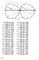
- the generating screw profile is represented by the left screw profile.
- the generated screw profile is represented by the right screw profile.
- the circular arcs of the generating and the generated screw profile are characterized by thick, solid lines, which are provided with the respective numbers of circular arcs. Due to the large number of circular arcs and due to the generation of the figures by means of a computer program, it may happen that the numbers of individual circular arcs overlap and are therefore difficult to read. Despite the partial poor readability of individual numbers, the structure of the profiles from the context in connection with the present description nevertheless becomes clear.
- the centers of the circular arcs are represented by small circles.
- the centers of the circular arcs are connected by thin, solid lines both to the starting point and to the end point of the associated circular arc.
- the worm outer radius is the same for the generating and the generated worm profile or approximately the same size. In the area of the worm housing, the worm outer radius is characterized by a thin, dashed line, in the gusset area by a thin, dotted line.
- Fig. 1 shows the cross-sectional profiles of a pair of profile different screw elements.
- the generating and the generated profile are each composed of 9 circular arcs. Below the FIG. 1 the coordinates of the centers of the respective circular arcs, their radii and the angles of the respective circular arcs are indicated.
- the circular arcs 1 and 1 ', 2 and 2', 3 and 3 ', etc. correspond to each other.
- the profiles of the adjacent elements are different.
- the profiles are not symmetrical. On the left side there is a large free cross-sectional area; on the right side over the circular arcs 5 ', 4' and 3 'extending tapering area.
- 5 F 1 1482 .
- 5 F 2 2010 .
- 5 F 1 free 1048 . 7
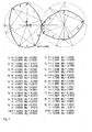
- Fig. 2 shows the cross-sectional profiles of a pair of inventive profile identical screw elements.
- the generating and the generated profile each consist of 14 circular arcs. Below the FIG. 2 the coordinates of the centers of the respective circular arcs, their radii and the angles of the respective circular arcs are indicated.
- the circular arcs 1 and 1 ', 2 and 2', 3 and 3 ', etc. correspond to each other.
- the profiles of the adjacent elements are identical.
- the profiles are not symmetrical.
- Each profile has a large tapering area (circular arcs 12, 11 and 10 or 5 ', 4' and 3 ') and a large free cross-sectional area on the opposite side of the profile.
- Fig. 3 shows the cross-sectional profiles of a pair of open screw elements.
- the generating and the generated profile are each composed of 10 circular arcs.
- Below the FIG. 3 the coordinates of the centers of the respective circular arcs, their radii and the angles of the respective circular arcs are indicated.
- the circular arcs 1 and 1 ', 2 and 2', 3 and 3 ', etc. correspond to each other.
- the profiles of the adjacent elements are different.
- the profiles are each symmetrical, they have a mirror plane.
- the generating left profile has exactly two comb areas (Circular arcs 3, 4 and 5, circular arcs 7, 8 and 9); the generated right profile has exactly one comb area (arcs 2 ', 1' and 10 ').
- F 1 1887 . 1
- F 2 1481 . 1
- F 1 free 644 .
- 4 F 2 free 1050 .
- 4 F 2 free 1 . 63
Landscapes
- Engineering & Computer Science (AREA)
- Mechanical Engineering (AREA)
- Physics & Mathematics (AREA)
- Algebra (AREA)
- General Physics & Mathematics (AREA)
- Mathematical Analysis (AREA)
- Mathematical Optimization (AREA)
- Mathematical Physics (AREA)
- Pure & Applied Mathematics (AREA)
- Manufacturing & Machinery (AREA)
- Extrusion Moulding Of Plastics Or The Like (AREA)
- Processing And Handling Of Plastics And Other Materials For Molding In General (AREA)
Applications Claiming Priority (2)
| Application Number | Priority Date | Filing Date | Title |
|---|---|---|---|
| DE102009059072A DE102009059072A1 (de) | 2009-12-18 | 2009-12-18 | Schneckenelemente zur Extrusion viskoelastischer Massen |
| EP10796002.3A EP2512775B1 (de) | 2009-12-18 | 2010-12-13 | Schneckenelemente zur extrusion viskoelastischer massen, verwendung und verfahren |
Related Parent Applications (3)
| Application Number | Title | Priority Date | Filing Date |
|---|---|---|---|
| EP10796002.3 Division | 2010-12-13 | ||
| EP10796002.3A Division EP2512775B1 (de) | 2009-12-18 | 2010-12-13 | Schneckenelemente zur extrusion viskoelastischer massen, verwendung und verfahren |
| EP10796002.3A Division-Into EP2512775B1 (de) | 2009-12-18 | 2010-12-13 | Schneckenelemente zur extrusion viskoelastischer massen, verwendung und verfahren |
Publications (2)
| Publication Number | Publication Date |
|---|---|
| EP2610045A1 EP2610045A1 (de) | 2013-07-03 |
| EP2610045B1 true EP2610045B1 (de) | 2015-03-04 |
Family
ID=43972738
Family Applications (2)
| Application Number | Title | Priority Date | Filing Date |
|---|---|---|---|
| EP13156356.1A Active EP2610045B1 (de) | 2009-12-18 | 2010-12-13 | Schneckenelemente zur Extrusion viskoelastischer Massen |
| EP10796002.3A Active EP2512775B1 (de) | 2009-12-18 | 2010-12-13 | Schneckenelemente zur extrusion viskoelastischer massen, verwendung und verfahren |
Family Applications After (1)
| Application Number | Title | Priority Date | Filing Date |
|---|---|---|---|
| EP10796002.3A Active EP2512775B1 (de) | 2009-12-18 | 2010-12-13 | Schneckenelemente zur extrusion viskoelastischer massen, verwendung und verfahren |
Country Status (13)
| Country | Link |
|---|---|
| US (1) | US8753003B2 (https=) |
| EP (2) | EP2610045B1 (https=) |
| JP (1) | JP5781533B2 (https=) |
| KR (1) | KR101801414B1 (https=) |
| CN (1) | CN102791462B (https=) |
| BR (1) | BR112012014909A2 (https=) |
| CA (2) | CA3004974C (https=) |
| DE (1) | DE102009059072A1 (https=) |
| MX (1) | MX2012006972A (https=) |
| MY (2) | MY159799A (https=) |
| RU (1) | RU2550175C9 (https=) |
| SG (1) | SG181602A1 (https=) |
| WO (1) | WO2011073121A2 (https=) |
Cited By (1)
| Publication number | Priority date | Publication date | Assignee | Title |
|---|---|---|---|---|
| WO2022084272A1 (de) * | 2020-10-22 | 2022-04-28 | Covestro Deutschland Ag | Extruder mit besonderer anordnung von asymmetrischen schneckenelementen auf schneckenwellen |
Families Citing this family (11)
| Publication number | Priority date | Publication date | Assignee | Title |
|---|---|---|---|---|
| DE102012214511A1 (de) | 2011-11-10 | 2013-05-16 | Leibniz-Institut Für Polymerforschung Dresden E.V. | Temperaturbeständige elastomere werkstoffe und ihre verwendung |
| EP2747980B1 (en) | 2012-02-28 | 2016-07-20 | Steer Engineering Private Limited | An extruder mixing element |
| EP2965889A1 (de) * | 2014-07-11 | 2016-01-13 | Covestro Deutschland AG | Mischelemente mit verbesserter Dispergierwirkung |
| CN105984110B (zh) | 2015-03-23 | 2019-10-15 | 思蒂亚工程私人有限公司 | 一种用于同向旋转的双螺杆加工设备的元件 |
| WO2017171666A1 (en) * | 2016-03-29 | 2017-10-05 | Ptt Global Chemical Public Company Limited | A method for preparing a blend composition of flour and polyolefin |
| JP2022522138A (ja) * | 2019-02-27 | 2022-04-14 | コベストロ・インテレクチュアル・プロパティ・ゲゼルシャフト・ミット・ベシュレンクテル・ハフツング・アンド・コー・カーゲー | 軸方向に非対称なスクリュー輪郭内に少なくとも2個の作図点を有するスクリュー輪郭を有するスクリュー要素 |
| CN110466133B (zh) * | 2019-07-26 | 2023-11-24 | 五邑大学 | 一种非对称同向多螺杆挤出装置、挤出机及其加工方法 |
| WO2022079534A1 (en) | 2020-10-15 | 2022-04-21 | Steer Engineering Private Limited | An element for a co-rotating twin-screw processor |
| CN113457502B (zh) * | 2021-07-05 | 2022-08-02 | 广西大学 | 一种搅拌装置及其搅拌器 |
| TWI830232B (zh) * | 2022-05-20 | 2024-01-21 | 國立高雄科技大學 | 雙螺桿裁切碳纖維回收料方法與裝置 |
| EP4470747A1 (en) * | 2023-05-29 | 2024-12-04 | Steer Engineering Private Limited | An element and a screw for a counter-rotating twin-screw processor |
Family Cites Families (19)
| Publication number | Priority date | Publication date | Assignee | Title |
|---|---|---|---|---|
| DE1180718B (de) | 1962-04-11 | 1964-11-05 | Bayer Ag | Knetvorrichtung mit zwei oder mehr Schnecken |
| JPS5829733B2 (ja) * | 1977-11-19 | 1983-06-24 | 積水化学工業株式会社 | 押出機 |
| JPS5944093B2 (ja) * | 1981-06-01 | 1984-10-26 | 株式会社神戸製鋼所 | 連続式混練機 |
| DE3206325C2 (de) * | 1982-02-22 | 1985-10-10 | AUTOMATIK Apparate-Maschinenbau GmbH, 8754 Großostheim | Mehrwellige, kontinuierlich arbeitende Misch- und Knetmaschine für plastifizierbare Massen |
| DE4239220C2 (de) | 1992-11-21 | 1996-08-22 | Blach Verfahrenstechnik Gmbh | Gleichdrall - Doppelschneckenextruder |
| DE19718292A1 (de) * | 1997-04-30 | 1998-11-05 | Krupp Werner & Pfleiderer Gmbh | Mehrwellen-Schneckenmaschine, insbesondere Zwei-Wellen-Extruder |
| US6116770A (en) * | 1998-10-02 | 2000-09-12 | Krupp Werner & Pfleiderer Corporation | Mixing element for screw extruder |
| DE19860256A1 (de) * | 1998-12-24 | 2000-06-29 | Krupp Werner & Pfleiderer Gmbh | Zwei-Wellen-Extruder |
| US6783270B1 (en) | 2000-07-31 | 2004-08-31 | Steer Engineering (P) Limited | Fractional and higher lobed co-rotating twin-screw elements |
| DE10112028A1 (de) * | 2001-03-06 | 2002-09-26 | Berstorff Gmbh | Schneckenpumpe und Doppelschneckenextruder mit einer solchen Schneckenpumpe |
| DE10114727B4 (de) * | 2001-03-22 | 2005-05-12 | Berstorff Gmbh | Schneckenelement für gleichsinnig drehende Mehrschneckenextruder |
| CN1956827B (zh) | 2004-06-03 | 2010-11-24 | 三菱重工业株式会社 | 连续混炼装置和使用该装置的混炼系统 |
| DE102005053907B4 (de) * | 2005-11-11 | 2009-05-20 | Blach Verwaltung Gmbh & Co.Kg | Mehrwellenextruder |
| JP4907366B2 (ja) * | 2007-01-26 | 2012-03-28 | 株式会社神戸製鋼所 | 押出機用スクリュ、これに用いられる軸受セグメント、および押出機用スクリュを備える2軸押出機 |
| CN201012534Y (zh) * | 2007-01-31 | 2008-01-30 | 中国化学工业桂林工程公司 | 冷喂料橡胶挤出机的强制喂料装置 |
| DE102008016862C5 (de) * | 2008-04-02 | 2019-12-19 | Blach Verwaltungs Gmbh & Co. Kg | Extruder |
| DE102008029305A1 (de) * | 2008-06-20 | 2009-12-24 | Bayer Technology Services Gmbh | Schneckenelemente mit reduziertem Kammwinkel |
| DE102008029304A1 (de) | 2008-06-20 | 2009-12-24 | Bayer Technology Services Gmbh | Verfahren zur Erzeugung von Schneckenelementen |
| KR101732206B1 (ko) * | 2009-09-29 | 2017-05-02 | 코페리온 게엠베하 | 다축 웜 기계에서 재료를 처리하기 위한 처리요소, 및 다축 웜 기계 |
-
2009
- 2009-12-18 DE DE102009059072A patent/DE102009059072A1/de not_active Withdrawn
-
2010
- 2010-12-13 KR KR1020127018669A patent/KR101801414B1/ko active Active
- 2010-12-13 MY MYPI2012002719A patent/MY159799A/en unknown
- 2010-12-13 US US13/516,055 patent/US8753003B2/en active Active
- 2010-12-13 MX MX2012006972A patent/MX2012006972A/es active IP Right Grant
- 2010-12-13 RU RU2012130171/05A patent/RU2550175C9/ru not_active IP Right Cessation
- 2010-12-13 WO PCT/EP2010/069470 patent/WO2011073121A2/de not_active Ceased
- 2010-12-13 CN CN201080064192.2A patent/CN102791462B/zh active Active
- 2010-12-13 BR BR112012014909A patent/BR112012014909A2/pt active Search and Examination
- 2010-12-13 EP EP13156356.1A patent/EP2610045B1/de active Active
- 2010-12-13 EP EP10796002.3A patent/EP2512775B1/de active Active
- 2010-12-13 CA CA3004974A patent/CA3004974C/en not_active Expired - Fee Related
- 2010-12-13 CA CA2784913A patent/CA2784913C/en not_active Expired - Fee Related
- 2010-12-13 JP JP2012543647A patent/JP5781533B2/ja active Active
- 2010-12-13 MY MYPI2015002824A patent/MY172336A/en unknown
- 2010-12-13 SG SG2012042487A patent/SG181602A1/en unknown
Cited By (1)
| Publication number | Priority date | Publication date | Assignee | Title |
|---|---|---|---|---|
| WO2022084272A1 (de) * | 2020-10-22 | 2022-04-28 | Covestro Deutschland Ag | Extruder mit besonderer anordnung von asymmetrischen schneckenelementen auf schneckenwellen |
Also Published As
| Publication number | Publication date |
|---|---|
| CA3004974C (en) | 2019-07-09 |
| BR112012014909A2 (pt) | 2017-03-21 |
| RU2550175C9 (ru) | 2016-01-20 |
| SG181602A1 (en) | 2012-07-30 |
| WO2011073121A2 (de) | 2011-06-23 |
| CA2784913C (en) | 2018-08-21 |
| MY172336A (en) | 2019-11-21 |
| JP5781533B2 (ja) | 2015-09-24 |
| MX2012006972A (es) | 2012-10-15 |
| CN102791462B (zh) | 2015-01-28 |
| WO2011073121A3 (de) | 2012-02-09 |
| DE102009059072A1 (de) | 2011-06-22 |
| CA2784913A1 (en) | 2011-06-23 |
| KR101801414B1 (ko) | 2017-11-24 |
| CA3004974A1 (en) | 2011-06-23 |
| RU2550175C2 (ru) | 2015-05-10 |
| JP2013514204A (ja) | 2013-04-25 |
| CN102791462A (zh) | 2012-11-21 |
| MY159799A (en) | 2017-01-31 |
| EP2610045A1 (de) | 2013-07-03 |
| EP2512775A2 (de) | 2012-10-24 |
| US20130033956A1 (en) | 2013-02-07 |
| EP2512775B1 (de) | 2014-06-11 |
| RU2012130171A (ru) | 2014-01-27 |
| US8753003B2 (en) | 2014-06-17 |
| KR20120124409A (ko) | 2012-11-13 |
Similar Documents
| Publication | Publication Date | Title |
|---|---|---|
| EP2610045B1 (de) | Schneckenelemente zur Extrusion viskoelastischer Massen | |
| EP2303544B1 (de) | Eingängige schneckenelemente mit reduziertem kammwinkel, verwendung und verfahren | |
| EP2291271B1 (de) | Verfahren zur extrusion plastischer massen | |
| EP2291270A1 (de) | Scheckenelemente mit reduziertem kammwinkel | |
| EP2906406B1 (de) | Extruder zur verarbeitung von kunststoffen, die zum verkleben neigen | |
| WO2009056083A1 (de) | Vorrichtung und verfahren zur verarbeitung polymerer werkstoffe | |
| EP3013551B1 (de) | Schneckenelemente für mehrwellige schneckenmaschinen und verfahren zu deren herstellung | |
| EP3930983B1 (de) | Schneckenelement mit nicht-achsensymmetrischem schneckenprofil und dessen verwendung | |
| DE19950917A1 (de) | Doppelschneckenextruder mit neuen Schneckenelementen | |
| EP4507871A1 (de) | Mehrwellige schneckenmaschine mit einem paar schneckenelementen mit verbesserter misch- und entgasungswirkung bei reduziertem energieeintrag | |
| EP3389967B1 (de) | Vorrichtung und verfahren zur dispergierung von feststoffen, flüssigkeiten und gasen in einem extruder | |
| EP4489956B1 (de) | Schneckenelemente mit verbesserter mischwirkung und druckaufbau | |
| EP4232259B1 (de) | Extruder mit besonderer anordnung von asymmetrischen schneckenelementen auf schneckenwellen | |
| EP4458548A1 (de) | Schneckenelemente mit verbesserter mischwirkung und verbessertem wärmeübergang und deren verwendung | |
| EP3276511A1 (de) | Herstellung von extrudern umfassend deren automatisierte auslegung | |
| DE102011054409B4 (de) | Extrudervorrichtung und Extrusionsverfahren, insbesondere zur Compoundierung von Kunststoffen | |
| EP3804934A1 (de) | Extruder mit schneckenelementen mit besonders grosser steigung im bereich der entgasungsöffnung | |
| DD216898A1 (de) | Gegenlaeufig kaemmende doppelschnecke |
Legal Events
| Date | Code | Title | Description |
|---|---|---|---|
| PUAI | Public reference made under article 153(3) epc to a published international application that has entered the european phase |
Free format text: ORIGINAL CODE: 0009012 |
|
| AC | Divisional application: reference to earlier application |
Ref document number: 2512775 Country of ref document: EP Kind code of ref document: P |
|
| AK | Designated contracting states |
Kind code of ref document: A1 Designated state(s): AL AT BE BG CH CY CZ DE DK EE ES FI FR GB GR HR HU IE IS IT LI LT LU LV MC MK MT NL NO PL PT RO RS SE SI SK SM TR |
|
| 17P | Request for examination filed |
Effective date: 20140103 |
|
| RBV | Designated contracting states (corrected) |
Designated state(s): AL AT BE BG CH CY CZ DE DK EE ES FI FR GB GR HR HU IE IS IT LI LT LU LV MC MK MT NL NO PL PT RO RS SE SI SK SM TR |
|
| RIC1 | Information provided on ipc code assigned before grant |
Ipc: B29C 47/60 20060101ALN20141023BHEP Ipc: B29C 47/76 20060101ALN20141023BHEP Ipc: B29C 47/40 20060101AFI20141023BHEP Ipc: B29C 47/10 20060101ALI20141023BHEP |
|
| GRAP | Despatch of communication of intention to grant a patent |
Free format text: ORIGINAL CODE: EPIDOSNIGR1 |
|
| RIC1 | Information provided on ipc code assigned before grant |
Ipc: B29C 47/60 20060101ALN20141027BHEP Ipc: B29C 47/40 20060101AFI20141027BHEP Ipc: B29C 47/10 20060101ALI20141027BHEP Ipc: B29C 47/76 20060101ALN20141027BHEP |
|
| INTG | Intention to grant announced |
Effective date: 20141201 |
|
| GRAS | Grant fee paid |
Free format text: ORIGINAL CODE: EPIDOSNIGR3 |
|
| GRAA | (expected) grant |
Free format text: ORIGINAL CODE: 0009210 |
|
| AC | Divisional application: reference to earlier application |
Ref document number: 2512775 Country of ref document: EP Kind code of ref document: P |
|
| AK | Designated contracting states |
Kind code of ref document: B1 Designated state(s): AL AT BE BG CH CY CZ DE DK EE ES FI FR GB GR HR HU IE IS IT LI LT LU LV MC MK MT NL NO PL PT RO RS SE SI SK SM TR |
|
| REG | Reference to a national code |
Ref country code: GB Ref legal event code: FG4D Free format text: NOT ENGLISH |
|
| REG | Reference to a national code |
Ref country code: CH Ref legal event code: EP |
|
| REG | Reference to a national code |
Ref country code: IE Ref legal event code: FG4D Free format text: LANGUAGE OF EP DOCUMENT: GERMAN |
|
| REG | Reference to a national code |
Ref country code: AT Ref legal event code: REF Ref document number: 713446 Country of ref document: AT Kind code of ref document: T Effective date: 20150415 |
|
| REG | Reference to a national code |
Ref country code: DE Ref legal event code: R096 Ref document number: 502010009088 Country of ref document: DE Effective date: 20150416 |
|
| REG | Reference to a national code |
Ref country code: NL Ref legal event code: VDEP Effective date: 20150304 |
|
| PG25 | Lapsed in a contracting state [announced via postgrant information from national office to epo] |
Ref country code: NO Free format text: LAPSE BECAUSE OF FAILURE TO SUBMIT A TRANSLATION OF THE DESCRIPTION OR TO PAY THE FEE WITHIN THE PRESCRIBED TIME-LIMIT Effective date: 20150604 Ref country code: HR Free format text: LAPSE BECAUSE OF FAILURE TO SUBMIT A TRANSLATION OF THE DESCRIPTION OR TO PAY THE FEE WITHIN THE PRESCRIBED TIME-LIMIT Effective date: 20150304 Ref country code: SE Free format text: LAPSE BECAUSE OF FAILURE TO SUBMIT A TRANSLATION OF THE DESCRIPTION OR TO PAY THE FEE WITHIN THE PRESCRIBED TIME-LIMIT Effective date: 20150304 Ref country code: FI Free format text: LAPSE BECAUSE OF FAILURE TO SUBMIT A TRANSLATION OF THE DESCRIPTION OR TO PAY THE FEE WITHIN THE PRESCRIBED TIME-LIMIT Effective date: 20150304 Ref country code: ES Free format text: LAPSE BECAUSE OF FAILURE TO SUBMIT A TRANSLATION OF THE DESCRIPTION OR TO PAY THE FEE WITHIN THE PRESCRIBED TIME-LIMIT Effective date: 20150304 Ref country code: LT Free format text: LAPSE BECAUSE OF FAILURE TO SUBMIT A TRANSLATION OF THE DESCRIPTION OR TO PAY THE FEE WITHIN THE PRESCRIBED TIME-LIMIT Effective date: 20150304 |
|
| REG | Reference to a national code |
Ref country code: LT Ref legal event code: MG4D |
|
| PG25 | Lapsed in a contracting state [announced via postgrant information from national office to epo] |
Ref country code: GR Free format text: LAPSE BECAUSE OF FAILURE TO SUBMIT A TRANSLATION OF THE DESCRIPTION OR TO PAY THE FEE WITHIN THE PRESCRIBED TIME-LIMIT Effective date: 20150605 Ref country code: LV Free format text: LAPSE BECAUSE OF FAILURE TO SUBMIT A TRANSLATION OF THE DESCRIPTION OR TO PAY THE FEE WITHIN THE PRESCRIBED TIME-LIMIT Effective date: 20150304 Ref country code: RS Free format text: LAPSE BECAUSE OF FAILURE TO SUBMIT A TRANSLATION OF THE DESCRIPTION OR TO PAY THE FEE WITHIN THE PRESCRIBED TIME-LIMIT Effective date: 20150304 |
|
| PG25 | Lapsed in a contracting state [announced via postgrant information from national office to epo] |
Ref country code: NL Free format text: LAPSE BECAUSE OF FAILURE TO SUBMIT A TRANSLATION OF THE DESCRIPTION OR TO PAY THE FEE WITHIN THE PRESCRIBED TIME-LIMIT Effective date: 20150304 |
|
| PG25 | Lapsed in a contracting state [announced via postgrant information from national office to epo] |
Ref country code: PT Free format text: LAPSE BECAUSE OF FAILURE TO SUBMIT A TRANSLATION OF THE DESCRIPTION OR TO PAY THE FEE WITHIN THE PRESCRIBED TIME-LIMIT Effective date: 20150706 Ref country code: CZ Free format text: LAPSE BECAUSE OF FAILURE TO SUBMIT A TRANSLATION OF THE DESCRIPTION OR TO PAY THE FEE WITHIN THE PRESCRIBED TIME-LIMIT Effective date: 20150304 Ref country code: RO Free format text: LAPSE BECAUSE OF FAILURE TO SUBMIT A TRANSLATION OF THE DESCRIPTION OR TO PAY THE FEE WITHIN THE PRESCRIBED TIME-LIMIT Effective date: 20150304 Ref country code: SK Free format text: LAPSE BECAUSE OF FAILURE TO SUBMIT A TRANSLATION OF THE DESCRIPTION OR TO PAY THE FEE WITHIN THE PRESCRIBED TIME-LIMIT Effective date: 20150304 Ref country code: EE Free format text: LAPSE BECAUSE OF FAILURE TO SUBMIT A TRANSLATION OF THE DESCRIPTION OR TO PAY THE FEE WITHIN THE PRESCRIBED TIME-LIMIT Effective date: 20150304 |
|
| REG | Reference to a national code |
Ref country code: FR Ref legal event code: PLFP Year of fee payment: 6 |
|
| PG25 | Lapsed in a contracting state [announced via postgrant information from national office to epo] |
Ref country code: PL Free format text: LAPSE BECAUSE OF FAILURE TO SUBMIT A TRANSLATION OF THE DESCRIPTION OR TO PAY THE FEE WITHIN THE PRESCRIBED TIME-LIMIT Effective date: 20150304 Ref country code: IS Free format text: LAPSE BECAUSE OF FAILURE TO SUBMIT A TRANSLATION OF THE DESCRIPTION OR TO PAY THE FEE WITHIN THE PRESCRIBED TIME-LIMIT Effective date: 20150704 |
|
| REG | Reference to a national code |
Ref country code: DE Ref legal event code: R097 Ref document number: 502010009088 Country of ref document: DE |
|
| PLBE | No opposition filed within time limit |
Free format text: ORIGINAL CODE: 0009261 |
|
| STAA | Information on the status of an ep patent application or granted ep patent |
Free format text: STATUS: NO OPPOSITION FILED WITHIN TIME LIMIT |
|
| REG | Reference to a national code |
Ref country code: DE Ref legal event code: R081 Ref document number: 502010009088 Country of ref document: DE Owner name: COVESTRO DEUTSCHLAND AG, DE Free format text: FORMER OWNER: BAYER INTELLECTUAL PROPERTY GMBH, 40789 MONHEIM, DE |
|
| PG25 | Lapsed in a contracting state [announced via postgrant information from national office to epo] |
Ref country code: DK Free format text: LAPSE BECAUSE OF FAILURE TO SUBMIT A TRANSLATION OF THE DESCRIPTION OR TO PAY THE FEE WITHIN THE PRESCRIBED TIME-LIMIT Effective date: 20150304 |
|
| 26N | No opposition filed |
Effective date: 20151207 |
|
| PG25 | Lapsed in a contracting state [announced via postgrant information from national office to epo] |
Ref country code: SI Free format text: LAPSE BECAUSE OF FAILURE TO SUBMIT A TRANSLATION OF THE DESCRIPTION OR TO PAY THE FEE WITHIN THE PRESCRIBED TIME-LIMIT Effective date: 20150304 |
|
| REG | Reference to a national code |
Ref country code: CH Ref legal event code: PUE Owner name: COVESTRO DEUTSCHLAND AG, DE Free format text: FORMER OWNER: BAYER INTELLECTUAL PROPERTY GMBH, DE |
|
| PG25 | Lapsed in a contracting state [announced via postgrant information from national office to epo] |
Ref country code: MC Free format text: LAPSE BECAUSE OF FAILURE TO SUBMIT A TRANSLATION OF THE DESCRIPTION OR TO PAY THE FEE WITHIN THE PRESCRIBED TIME-LIMIT Effective date: 20150304 Ref country code: LU Free format text: LAPSE BECAUSE OF FAILURE TO SUBMIT A TRANSLATION OF THE DESCRIPTION OR TO PAY THE FEE WITHIN THE PRESCRIBED TIME-LIMIT Effective date: 20151213 |
|
| REG | Reference to a national code |
Ref country code: IE Ref legal event code: MM4A |
|
| REG | Reference to a national code |
Ref country code: GB Ref legal event code: 732E Free format text: REGISTERED BETWEEN 20160922 AND 20160928 |
|
| PG25 | Lapsed in a contracting state [announced via postgrant information from national office to epo] |
Ref country code: IE Free format text: LAPSE BECAUSE OF NON-PAYMENT OF DUE FEES Effective date: 20151213 |
|
| REG | Reference to a national code |
Ref country code: FR Ref legal event code: PLFP Year of fee payment: 7 |
|
| REG | Reference to a national code |
Ref country code: FR Ref legal event code: TP Owner name: COVESTRO DEUTSCHLAND AG, DE Effective date: 20161115 |
|
| REG | Reference to a national code |
Ref country code: AT Ref legal event code: PC Ref document number: 713446 Country of ref document: AT Kind code of ref document: T Owner name: COVESTRO DEUTSCHLAND AG, DE Effective date: 20161219 |
|
| PG25 | Lapsed in a contracting state [announced via postgrant information from national office to epo] |
Ref country code: SM Free format text: LAPSE BECAUSE OF FAILURE TO SUBMIT A TRANSLATION OF THE DESCRIPTION OR TO PAY THE FEE WITHIN THE PRESCRIBED TIME-LIMIT Effective date: 20150304 Ref country code: BG Free format text: LAPSE BECAUSE OF FAILURE TO SUBMIT A TRANSLATION OF THE DESCRIPTION OR TO PAY THE FEE WITHIN THE PRESCRIBED TIME-LIMIT Effective date: 20150304 Ref country code: HU Free format text: LAPSE BECAUSE OF FAILURE TO SUBMIT A TRANSLATION OF THE DESCRIPTION OR TO PAY THE FEE WITHIN THE PRESCRIBED TIME-LIMIT; INVALID AB INITIO Effective date: 20101213 |
|
| PG25 | Lapsed in a contracting state [announced via postgrant information from national office to epo] |
Ref country code: CY Free format text: LAPSE BECAUSE OF FAILURE TO SUBMIT A TRANSLATION OF THE DESCRIPTION OR TO PAY THE FEE WITHIN THE PRESCRIBED TIME-LIMIT Effective date: 20150304 |
|
| PG25 | Lapsed in a contracting state [announced via postgrant information from national office to epo] |
Ref country code: MT Free format text: LAPSE BECAUSE OF FAILURE TO SUBMIT A TRANSLATION OF THE DESCRIPTION OR TO PAY THE FEE WITHIN THE PRESCRIBED TIME-LIMIT Effective date: 20150304 |
|
| REG | Reference to a national code |
Ref country code: FR Ref legal event code: PLFP Year of fee payment: 8 |
|
| PG25 | Lapsed in a contracting state [announced via postgrant information from national office to epo] |
Ref country code: MK Free format text: LAPSE BECAUSE OF FAILURE TO SUBMIT A TRANSLATION OF THE DESCRIPTION OR TO PAY THE FEE WITHIN THE PRESCRIBED TIME-LIMIT Effective date: 20150304 Ref country code: TR Free format text: LAPSE BECAUSE OF FAILURE TO SUBMIT A TRANSLATION OF THE DESCRIPTION OR TO PAY THE FEE WITHIN THE PRESCRIBED TIME-LIMIT Effective date: 20150304 |
|
| PG25 | Lapsed in a contracting state [announced via postgrant information from national office to epo] |
Ref country code: AL Free format text: LAPSE BECAUSE OF FAILURE TO SUBMIT A TRANSLATION OF THE DESCRIPTION OR TO PAY THE FEE WITHIN THE PRESCRIBED TIME-LIMIT Effective date: 20150304 |
|
| REG | Reference to a national code |
Ref country code: DE Ref legal event code: R079 Ref document number: 502010009088 Country of ref document: DE Free format text: PREVIOUS MAIN CLASS: B29C0047400000 Ipc: B29C0048400000 |
|
| PGFP | Annual fee paid to national office [announced via postgrant information from national office to epo] |
Ref country code: BE Payment date: 20191125 Year of fee payment: 10 Ref country code: FR Payment date: 20191128 Year of fee payment: 10 |
|
| PGFP | Annual fee paid to national office [announced via postgrant information from national office to epo] |
Ref country code: AT Payment date: 20191125 Year of fee payment: 10 |
|
| REG | Reference to a national code |
Ref country code: AT Ref legal event code: MM01 Ref document number: 713446 Country of ref document: AT Kind code of ref document: T Effective date: 20201213 |
|
| REG | Reference to a national code |
Ref country code: BE Ref legal event code: MM Effective date: 20201231 |
|
| PG25 | Lapsed in a contracting state [announced via postgrant information from national office to epo] |
Ref country code: AT Free format text: LAPSE BECAUSE OF NON-PAYMENT OF DUE FEES Effective date: 20201213 Ref country code: FR Free format text: LAPSE BECAUSE OF NON-PAYMENT OF DUE FEES Effective date: 20201231 |
|
| PGFP | Annual fee paid to national office [announced via postgrant information from national office to epo] |
Ref country code: GB Payment date: 20211118 Year of fee payment: 12 |
|
| PGFP | Annual fee paid to national office [announced via postgrant information from national office to epo] |
Ref country code: CH Payment date: 20211126 Year of fee payment: 12 |
|
| PG25 | Lapsed in a contracting state [announced via postgrant information from national office to epo] |
Ref country code: BE Free format text: LAPSE BECAUSE OF NON-PAYMENT OF DUE FEES Effective date: 20201231 |
|
| REG | Reference to a national code |
Ref country code: CH Ref legal event code: PL |
|
| GBPC | Gb: european patent ceased through non-payment of renewal fee |
Effective date: 20221213 |
|
| PG25 | Lapsed in a contracting state [announced via postgrant information from national office to epo] |
Ref country code: LI Free format text: LAPSE BECAUSE OF NON-PAYMENT OF DUE FEES Effective date: 20221231 Ref country code: GB Free format text: LAPSE BECAUSE OF NON-PAYMENT OF DUE FEES Effective date: 20221213 Ref country code: CH Free format text: LAPSE BECAUSE OF NON-PAYMENT OF DUE FEES Effective date: 20221231 |
|
| PGFP | Annual fee paid to national office [announced via postgrant information from national office to epo] |
Ref country code: DE Payment date: 20251119 Year of fee payment: 16 |
|
| PGFP | Annual fee paid to national office [announced via postgrant information from national office to epo] |
Ref country code: IT Payment date: 20251126 Year of fee payment: 16 |