EP2608980B1 - Multi-system traction power converter - Google Patents
Multi-system traction power converter Download PDFInfo
- Publication number
- EP2608980B1 EP2608980B1 EP11714533.4A EP11714533A EP2608980B1 EP 2608980 B1 EP2608980 B1 EP 2608980B1 EP 11714533 A EP11714533 A EP 11714533A EP 2608980 B1 EP2608980 B1 EP 2608980B1
- Authority
- EP
- European Patent Office
- Prior art keywords
- power converter
- voltage
- converter
- output
- series
- Prior art date
- Legal status (The legal status is an assumption and is not a legal conclusion. Google has not performed a legal analysis and makes no representation as to the accuracy of the status listed.)
- Active
Links
- 238000004804 winding Methods 0.000 claims description 21
- 239000003990 capacitor Substances 0.000 claims description 8
- 238000010586 diagram Methods 0.000 description 2
- 230000007935 neutral effect Effects 0.000 description 2
- 239000004065 semiconductor Substances 0.000 description 2
Images


Classifications
-
- B—PERFORMING OPERATIONS; TRANSPORTING
- B60—VEHICLES IN GENERAL
- B60L—PROPULSION OF ELECTRICALLY-PROPELLED VEHICLES; SUPPLYING ELECTRIC POWER FOR AUXILIARY EQUIPMENT OF ELECTRICALLY-PROPELLED VEHICLES; ELECTRODYNAMIC BRAKE SYSTEMS FOR VEHICLES IN GENERAL; MAGNETIC SUSPENSION OR LEVITATION FOR VEHICLES; MONITORING OPERATING VARIABLES OF ELECTRICALLY-PROPELLED VEHICLES; ELECTRIC SAFETY DEVICES FOR ELECTRICALLY-PROPELLED VEHICLES
- B60L9/00—Electric propulsion with power supply external to the vehicle
- B60L9/16—Electric propulsion with power supply external to the vehicle using AC induction motors
- B60L9/18—Electric propulsion with power supply external to the vehicle using AC induction motors fed from DC supply lines
- B60L9/22—Electric propulsion with power supply external to the vehicle using AC induction motors fed from DC supply lines polyphase motors
-
- B—PERFORMING OPERATIONS; TRANSPORTING
- B60—VEHICLES IN GENERAL
- B60L—PROPULSION OF ELECTRICALLY-PROPELLED VEHICLES; SUPPLYING ELECTRIC POWER FOR AUXILIARY EQUIPMENT OF ELECTRICALLY-PROPELLED VEHICLES; ELECTRODYNAMIC BRAKE SYSTEMS FOR VEHICLES IN GENERAL; MAGNETIC SUSPENSION OR LEVITATION FOR VEHICLES; MONITORING OPERATING VARIABLES OF ELECTRICALLY-PROPELLED VEHICLES; ELECTRIC SAFETY DEVICES FOR ELECTRICALLY-PROPELLED VEHICLES
- B60L9/00—Electric propulsion with power supply external to the vehicle
- B60L9/16—Electric propulsion with power supply external to the vehicle using AC induction motors
- B60L9/30—Electric propulsion with power supply external to the vehicle using AC induction motors fed from different kinds of power-supply lines
-
- B—PERFORMING OPERATIONS; TRANSPORTING
- B60—VEHICLES IN GENERAL
- B60L—PROPULSION OF ELECTRICALLY-PROPELLED VEHICLES; SUPPLYING ELECTRIC POWER FOR AUXILIARY EQUIPMENT OF ELECTRICALLY-PROPELLED VEHICLES; ELECTRODYNAMIC BRAKE SYSTEMS FOR VEHICLES IN GENERAL; MAGNETIC SUSPENSION OR LEVITATION FOR VEHICLES; MONITORING OPERATING VARIABLES OF ELECTRICALLY-PROPELLED VEHICLES; ELECTRIC SAFETY DEVICES FOR ELECTRICALLY-PROPELLED VEHICLES
- B60L2200/00—Type of vehicles
- B60L2200/26—Rail vehicles
-
- B—PERFORMING OPERATIONS; TRANSPORTING
- B60—VEHICLES IN GENERAL
- B60L—PROPULSION OF ELECTRICALLY-PROPELLED VEHICLES; SUPPLYING ELECTRIC POWER FOR AUXILIARY EQUIPMENT OF ELECTRICALLY-PROPELLED VEHICLES; ELECTRODYNAMIC BRAKE SYSTEMS FOR VEHICLES IN GENERAL; MAGNETIC SUSPENSION OR LEVITATION FOR VEHICLES; MONITORING OPERATING VARIABLES OF ELECTRICALLY-PROPELLED VEHICLES; ELECTRIC SAFETY DEVICES FOR ELECTRICALLY-PROPELLED VEHICLES
- B60L2210/00—Converter types
- B60L2210/30—AC to DC converters
-
- B—PERFORMING OPERATIONS; TRANSPORTING
- B60—VEHICLES IN GENERAL
- B60L—PROPULSION OF ELECTRICALLY-PROPELLED VEHICLES; SUPPLYING ELECTRIC POWER FOR AUXILIARY EQUIPMENT OF ELECTRICALLY-PROPELLED VEHICLES; ELECTRODYNAMIC BRAKE SYSTEMS FOR VEHICLES IN GENERAL; MAGNETIC SUSPENSION OR LEVITATION FOR VEHICLES; MONITORING OPERATING VARIABLES OF ELECTRICALLY-PROPELLED VEHICLES; ELECTRIC SAFETY DEVICES FOR ELECTRICALLY-PROPELLED VEHICLES
- B60L2210/00—Converter types
- B60L2210/40—DC to AC converters
-
- Y—GENERAL TAGGING OF NEW TECHNOLOGICAL DEVELOPMENTS; GENERAL TAGGING OF CROSS-SECTIONAL TECHNOLOGIES SPANNING OVER SEVERAL SECTIONS OF THE IPC; TECHNICAL SUBJECTS COVERED BY FORMER USPC CROSS-REFERENCE ART COLLECTIONS [XRACs] AND DIGESTS
- Y02—TECHNOLOGIES OR APPLICATIONS FOR MITIGATION OR ADAPTATION AGAINST CLIMATE CHANGE
- Y02T—CLIMATE CHANGE MITIGATION TECHNOLOGIES RELATED TO TRANSPORTATION
- Y02T10/00—Road transport of goods or passengers
- Y02T10/60—Other road transportation technologies with climate change mitigation effect
- Y02T10/72—Electric energy management in electromobility
Definitions
- the invention relates to a multi-system traction converter according to the preamble of claim 1.
- a mains frequency transformerless traction converter is from the publication entitled “ 15kV / 16.7Hz Energy Supply System with Medium Frequency Transformer and 6.5kV IGBTs in Resonant Operation "by B. Engel, M. Victor, G. Bachmann and A. Falk, published in the conference proceedings of the 2003 EPE Conference in Toulouse , known.
- Such a traction converter has a feed device on the line side and a self-commutated pulse converter on the load side, to the outputs of which a drive motor is connected.
- the feeding device has, on the network side, a multiplicity of converter groups, a medium-frequency transformer and an output converter.
- the medium frequency transformer has a plurality of primary windings and a secondary winding, which are magnetically coupled together by means of a core.
- Each converter group is connected on the transformer side to a primary winding.
- On the network side each power converter group has a four-quadrant controller. These converter groups are connected in series on the line side. As a result, a network voltage of, for example, 15kV, 16.7Hz divided evenly into partial voltages.
- each converter group On the transformer side, each converter group has a series resonant converter. This series resonant power converter has a series capacitor which forms a series resonant circuit with a leakage inductance of an associated primary winding.
- the mains frequency is converted from 16.7 Hz into a higher-frequency transformer frequency of, for example, 5 kHz.
- a higher-frequency transformer frequency of, for example, 5 kHz.
- an otherwise used traction transformer is replaced, which is large and heavy, especially at a network frequency of 16.7 Hz.
- the transformer frequency at 5kHz is a technically realistic tradeoff between the volume and weight of the mid-frequency transformer and the switching losses.
- a power frequency travoloser traction converter known, which can also be powered by a DC network voltage of 1.5kV or 3kV.
- a low mains DC voltage of 1.5 kV is directly linked to the DC-side outputs of the output converter of the feeder by means of a switching device.
- a DC intermediate circuit Connected to these outputs is a DC intermediate circuit to which the load-side self-commutated pulse-controlled converter of the traction converter is connected on the DC voltage side.
- a positive potential rail of the voltage intermediate circuit is connected by means of a current collector with a mains DC voltage of, for example, 1.5 kV, which is applied to a catenary.
- a negative potential rail is connected to a drive wheel of a rail-bound vehicle, which is grounded by means of a rail.
- this circuit can also be operated advantageously to a mains voltage of 3kV.
- This traction converter can be operated on AC voltages of 15kV, 16.7Hz or 25kV, 50Hz and on a DC voltage of 1,5kV or 3kV.
- this feed circuit Disadvantage of this feed circuit is that a plurality of mechanical switches must be used to reconfigure the network-side converter groups of this feed circuit of a series circuit in a parallel circuit.
- an intermediate circuit voltage of a traction converter is 3 kV
- 6.5 kV IGBTs are used as turn-off power semiconductor switches of a load-side, self-commutated pulse-controlled converter, whereas at one amplitude of the intermediate circuit voltage of 1.5kV 3.3kV IGBTs. If the amplitude of the intermediate circuit voltage is 3 kV, this known traction converter can not be operated on all four web tension systems, so that this traction converter is not a multi-system traction converter with full multi-system capability.
- the invention is based on the object, this known Tratechnischsstromrichter further such that it can be operated on all four known web tension systems.
- a further output power converter is provided, which is linked on the alternating voltage side with a further secondary winding of the medium-frequency transformer, these two output power converters are coupled together AC voltage side.
- two switching devices are provided with which the two output power converters can be reconfigured as a function of a line voltage on the DC side in a parallel or series connection. This allows connection to a mains DC voltage of 1.5kV as well as 3kV.
- FIG. 1 shows a schematic diagram of one of the EP 1 226 994 A2 known Trakomsstromrichters.
- This known mains frequency travoloser traction converter has on the network side a feeding device 2, which is connected on the DC side by means of a voltage intermediate circuit 4 with a load-side self-commutated pulse converter 6, at the outputs of a drive motor 8 is connected.
- a positive potential rail 10 of the voltage intermediate circuit 4 is connected by means of a throttle 12 and a contactor 14 with a current collector 16 which is in electrical contact with a catenary 18, to which a DC line voltage of 1.5 kV, for example.
- a negative potential rail 20 of the DC intermediate circuit 4 is electrically connected by means of a further contactor 22 with a drive wheel 24 of a rail-bound vehicle, which is grounded by means of a rail 26.
- the supply device 2 is the network side by means of an input inductor L F , a contactor 28 and a current collector 30 connected to a catenary 32, to which either a mains AC voltage of 15kV, 16.7Hz or 25kV, 50Hz is pending.
- This feed device 2 has on the network side a multiplicity of power converter groups 34, which are connected in series in series and which are each connected to a primary winding 36 of a medium-frequency transformer 38 on the load side.
- This plurality of primary windings 36 and a secondary winding 40 of this medium-frequency transformer 38 are arranged in common on a magnetic core 42. As a result, these primary windings 36 and the secondary winding 40 are magnetically coupled to one another.
- Each power converter group 34 has a four-quadrant generator 44 on the network side and transformer side a resonant power converter 46, this DC voltage side is connected to DC side terminals of the four-quadrant 44.
- Implementation proposals of the Vierquadrantenstellers 44 and the resonant power converter 46 are the EP-Offenlegungsschrift or the aforementioned publication can be removed.
- This feed device 2 also has, on the output side, an output converter 48, which is electrically connected on the alternating voltage side to the secondary winding 40 of the medium-frequency transformer 38. According to the EP-Offenlegungsschrift or the publication mentioned above, this output power converter 48 is designed as a four-quadrant controller. Its DC-side terminals, each forming an output of the feed circuit are electrically connected to the positive and negative potential rail 10 and 20 of the DC intermediate circuit 4 of the traction converter.
- this feed device 2 is a DC voltage of 25kV, 50Hz, in particular a DC voltage of 15kV, 16.7Hz, a DC voltage of 1.5kV or 3kV generated, being dispensed with a conventional traction transformer. From this generated DC voltage of 1.5 kV or 3 kV, a three-phase alternating voltage with variable amplitude and frequency for feeding the drive motor 8 of a rail-bound vehicle is generated by means of the self-commutated pulse converter 6.
- the DC link voltage corresponds in amplitude to a DC network voltage of 1.5 kV or 3 kV
- this DC network voltage can be fed directly into the voltage intermediate circuit 4 of the traction converter.
- the mains voltage of 1.5 kV or 3 kV can be fed in. If the load-side self-commutated pulse-controlled converter 6 is dimensioned for an input DC voltage in the amount of 1.5 kV or 3 kV, only a DC network voltage which corresponds in amplitude to less than or equal to this DC input voltage can be used. The Use of the second mains DC voltage is then no longer possible without additional converter circuits.
- FIGS. 2 to 4 a first embodiment of a multi-system traction converter according to the invention with different mains voltage feeds and a DC link DC voltages in the amount of 1.5 kV is shown.
- this multi-system traction converter has a second output converter 50, which is connected on the alternating voltage side to a second secondary winding 52.
- This second secondary winding 52 is likewise arranged, like the other windings 36 and 40, on the magnetic core 42 of the medium-frequency transformer 38.
- two switching devices 54 and 56 are provided. By means of these two switching devices 54 and 56, the two output converters 48 and 50 are the DC side in a parallel or series connection reconfigurable.
- This multi-system traction converter is operated on one of the two possible mains AC voltages.
- the two output converters 48 and 50 of the feed device 2 are electrically connected in parallel on the DC voltage side.
- This DC-side parallel connection of the two output converters 48 and 50 is achieved in that a positive DC output of the output converter 48 is linked to a first input of the switching device 56, the output of which is connected to a positive DC output of the second output converter 50 and are electrically connected to a positive DC voltage terminal of the self-commutated pulse converter 6.
- a negative DC voltage output of the first output power converter 48 is electrically connected to an output of the switching device 54, whose first input is connected to a negative DC voltage output of the second output power converter 50 and is electrically connected to a positive DC voltage terminal of the self-commutated pulse converter 6.
- the two switching devices 54 and 56 are thus in a first of three possible switching positions.
- the two contactors 14 and 22 are open at an AC supply.
- the self-commutated pulse-controlled converter 6 is dimensioned in this embodiment for an input DC voltage in the amount of 1.5 kV.
- the two output converters 48 and 50 each deliver such a DC voltage of 1.5 kV.
- FIG. 3 is the multi-system traction converter according to the invention for a DC power supply in the amount of 3kV shown. Since the self-commutated pulse-controlled converter 6 is only dimensioned for an input DC voltage in the amount of 1.5 kV, the mains DC voltage must be halved.
- the two output converters 48 and 50 are electrically reconfigured in a series connection on the DC side.
- the two switching devices 54 and 56 are brought into their second switching position. That is, the second input of the switching device 56 is linked to a second input of the switching device 54.
- the contactors 14 and 22 are closed, so that the pantograph 16 is connected by means of the contactor 14 and the throttle 12 with a positive DC voltage output of the first output power converter 48.
- the negative DC output of the second output power converter 50 and the DC terminal of the self-commutated pulse-controlled converter 6 is linked by means of the contactor 22 to the drive wheel 24 of a rail-bound vehicle, which is grounded by means of a rail 26.
- the mains DC voltage in the amount of 3kV for the load-side self-commutated pulse converter 6 is halved.
- the power flow is closed via the magnetically coupled secondary windings 40 and 52.
- the FIG. 4 shows the multi-system traction converter according to the invention in a DC voltage supply in the amount of 1.5 kV.
- This DC voltage corresponds in amplitude to the DC input voltage of the self-commutated pulse converter 6 and thus also the DC voltage of the DC intermediate circuit 4 of the traction converter.
- the load-side self-commutated pulse-controlled converter 6 is grounded in the DC voltage path, which is formed by the catenary 18, the contactor 14, the inductor 12, the two DC terminals of the load-side self-commutated pulse-controlled converter 6 and the drive wheel 24 of a rail vehicle, by means of a rail 26 is grounded.
- the switching device 54 is brought into its third switching position, namely the neutral switching position, whereas the switching device 56 is again controlled in its first switching position. That is, the contact line 18 is connected by means of the contactor 14 and the throttle 12 and a first input of the switching device 56 to a positive DC voltage terminal of the load-side self-commutated pulse-controlled converter 6.
- the contactor 28 With a supply with a mains DC voltage of 1.5 kV or 3 kV, the contactor 28 is opened, so that no voltage is present at the series-connected power converter groups 34.
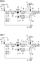
- FIGS. 5 to 7 a second embodiment of a multi-system traction converter according to the invention at different mains voltage feeds and a DC link voltage in the amount of 3kV is shown schematically. Also in these illustrations is because of the clarity of the feeding device 2 according to FIG. 1 only one power converter assembly 34 and the DC side output converter 48 is shown. Also, the feed device 2 of this second embodiment of the multi-system traction converter according to the invention comprises a second output converter 50, which is also the AC side with a core 42 of the medium-frequency transformer 38 applied second secondary winding 52 is electrically connected. For the reconfiguration of the two output converters 48 and 50 of the feed device 2 on the DC side in a parallel or series connection two switching devices 54 and 56 are provided, which are but differently connected to the first embodiment.
- the switching device 54 is the output side electrically connected to a negative DC voltage terminal of the load-side self-commutated pulse-controlled converter 6, wherein the first input is associated with a negative DC voltage output of the second output power converter 50.
- the second input of this switching device 54 is linked to a first input of the switching device 56, whose output is electrically connected to the drive wheel 22 of a rail vehicle.
- the second input of this switching device 56 is electrically connected to a negative DC voltage output of the first output power converter 48 and to a positive DC output of the second output power converter 50 of the feed device 2.
- a DC intermediate circuit 4 of the traction converter has a DC voltage with an amplitude of 3 kV.
- the load-side self-commutated pulse-controlled converter 6 uses 6.5kV IGBTs instead of 3.3kV IGBTs as turn-off power semiconductor switches.
- FIG. 5 is the multi-system traction converter according to the invention at a supply with a mains AC voltage of 25kV, 50Hz or 15kV, 16.7Hz shown.
- the two output converters 48 and 50 of the feed device 2 are electrically connected in parallel on the DC voltage side. This parallel connection will achieved when the switching device 54 is controlled in its first switching position.
- the negative DC voltage terminal of the load-side self-commutated pulse-controlled converter 6 is linked to the negative DC output of the second output power converter 50 of the feed device 2.
- the switching device 56 is at this time in a neutral switching position, its third switching position.
- the contactor 28 is closed, so that the AC line voltage of the catenary 32 is applied to the power converter groups 34 connected in series.
- the traction converter is shown according to the invention at a supply of a DC network voltage with an amplitude of 3kV.
- This DC network voltage corresponds in amplitude to the DC input voltage of the load-side self-commutated pulse converter 6 and thus the DC voltage of the DC link 4.
- the switching device 54 is controlled in its second switching position. That is, the DC terminal of the load-side self-commutated pulse-controlled converter 6 is connected to the drive wheel 24 by means of the second input of the switching device 54.
- the second switching device 56 is controlled in a first switching position.
- FIG. 7 the traction converter is shown according to the invention at a supply of a DC voltage with an amplitude of 1.5 kV.
- This DC voltage is equal to half the amplitude of the DC voltage of the DC intermediate circuit 4 and thus the DC input voltage of the load-side self-commutated pulse converter 6. So this load-side self-commutated pulse converter 6 can be operated, the mains DC voltage must be doubled in amplitude.
- the switching device 54 changes back to its first switching position and the switching device 56 in its second switching position.
- the positive DC voltage output of the first output power converter 48 of the feed device 2 and the positive DC voltage connection of the load-side self-commutated pulse-controlled converter 6 are linked together by means of the positive potential rail 10 of the DC intermediate circuit 4, wherein the throttle 12 with a connection with this positive potential rail 10 is connected. Because these two switching devices 54 and 56 are controlled in the specified switching positions, the DC voltages generated at the two output converters 48 and 50 each add an amplitude of 1.5 kV to the DC voltage of the DC intermediate circuit 4 with an amplitude of 3 kV ,
Landscapes
- Engineering & Computer Science (AREA)
- Life Sciences & Earth Sciences (AREA)
- Sustainable Development (AREA)
- Sustainable Energy (AREA)
- Power Engineering (AREA)
- Transportation (AREA)
- Mechanical Engineering (AREA)
- Electric Propulsion And Braking For Vehicles (AREA)
Description
Die Erfindung bezieht sich auf einen Mehrsystem-Traktionsstromrichter gemäß Oberbegriff des Anspruchs 1.The invention relates to a multi-system traction converter according to the preamble of
Ein netzfrequent trafoloser Traktionsstromrichter ist aus der Veröffentlichung mit dem Titel "
Aus der
Nachteil dieser Einspeiseschaltung besteht darin, dass eine Vielzahl von mechanischen Schaltern verwendet werden müssen, um die netzseitigen Stromrichter-Gruppen dieser Einspeiseschaltung von einer Reihenschaltung in eine Parallelschaltung umzukonfigurieren.Disadvantage of this feed circuit is that a plurality of mechanical switches must be used to reconfigure the network-side converter groups of this feed circuit of a series circuit in a parallel circuit.
Beträgt die Amplitude einer Zwischenkreisspannung eines Traktionsstromrichters 3kV, werden als abschaltbare Leistungshalbleiterschalter eines lastseitigen selbstgeführten Pulsstromrichters 6,5kV-IGBTs verwendet, wogegen bei einer Amplitude der Zwischenkreisspannung in Höhe von 1,5kV 3,3kV-IGBTs verwendet werden. Beträgt die Amplitude der Zwischenkreisspannung 3kV kann dieser bekannte Traktionsstromrichter nicht an allen vier Bahnspannungssystemen betrieben werden, so dass es sich bei diesem Traktionsstromrichter nicht um einen Mehrsystem-Traktionsstromrichter mit voller Mehrsystemfähigkeit handelt.If the amplitude of an intermediate circuit voltage of a traction converter is 3 kV, 6.5 kV IGBTs are used as turn-off power semiconductor switches of a load-side, self-commutated pulse-controlled converter, whereas at one amplitude of the intermediate circuit voltage of 1.5kV 3.3kV IGBTs. If the amplitude of the intermediate circuit voltage is 3 kV, this known traction converter can not be operated on all four web tension systems, so that this traction converter is not a multi-system traction converter with full multi-system capability.
Der Erfindung liegt nun die Aufgabe zugrunde, diesen bekannten Traktionsstromrichter derart weiterzubilden, dass dieser an allen vier bekannten Bahnspannungssystemen betrieben werden kann.The invention is based on the object, this known Traktionsstromrichter further such that it can be operated on all four known web tension systems.
Diese Aufgabe wird im Zusammenhang mit den Merkmalen des Oberbegriffs mit den kennzeichnenden Merkmalen des Anspruchs 1 erfindungsgemäß gelöst.This object is achieved in connection with the features of the preamble with the characterizing features of
Dadurch, dass ein weiterer Ausgangs-Stromrichter vorgesehen ist, der wechselspannungsseitig mit einer weiteren Sekundärwicklung des Mittelfrequenz-Transformators verknüpft ist, sind diese beiden Ausgangs-Stromrichter wechselspannungsseitig miteinander verkoppelt. Außerdem sind zwei Schaltgeräte vorgesehen, mit denen die beiden Ausgangs-Stromrichter in Abhängigkeit einer Fahrleitungsspannung gleichspannungsseitig in eine Parallel- oder Reihenschaltung umkonfigurierbar sind. Dadurch wird eine Anschaltung an eine Netzgleichspannung in Höhe von 1,5kV als auch von 3kV ermöglicht.Characterized in that a further output power converter is provided, which is linked on the alternating voltage side with a further secondary winding of the medium-frequency transformer, these two output power converters are coupled together AC voltage side. In addition, two switching devices are provided with which the two output power converters can be reconfigured as a function of a line voltage on the DC side in a parallel or series connection. This allows connection to a mains DC voltage of 1.5kV as well as 3kV.
Zur weiteren Erläuterung der Erfindung wird auf die Zeichnung Bezug genommen, in der zwei Ausführungsformen des erfindungsgemäßen Mehrsystem-Traktionsstromrichters schematisch veranschaulicht sind.
- FIG 1
- zeigt ein Prinzipschaltbild eines bekannten Traktionsstromrichters und in den
- FIG 2 bis 4
- sind eine erste Ausführungsform eines erfindungsgemäßen Mehrsystem-Traktionsstromrichters an unterschiedlichen Fahrleitungsspannungen dargestellt, wobei in den
- FIG 5 bis 7
- eine zweite Ausführungsform des erfindungsgemäßen Mehrsystem-Traktionsstromrichters an unterschiedlichen Fahrleitungsspannungen schematisch dargestellt sind.
- FIG. 1
- shows a schematic diagram of a known traction converter and in the
- FIGS. 2 to 4
- are a first embodiment of a multi-system traction converter according to the invention shown at different catenary voltages, wherein in the
- FIGS. 5 to 7
- a second embodiment of the multi-system traction converter according to the invention are shown schematically at different catenary voltages.
Die
Die Einspeisevorrichtung 2 ist netzseitig mittels einer Eingangsdrossel LF, eines Schützes 28 und eines Stromabnehmers 30 mit einer Fahrleitung 32 verbindbar, an dem entweder eine Netzwechselspannung von 15kV, 16.7Hz oder von 25kV, 50Hz ansteht. Diese Einspeisevorrichtung 2 weist netzseitig eine Vielzahl von elektrisch in Reihe geschalteten Stromrichter-Gruppen 34 auf, die lastseitig jeweils mit einer Primärwicklung 36 eines Mittelfrequenz-Transformators 38 verknüpft sind. Diese Vielzahl von Primärwicklungen 36 und eine Sekundärwicklung 40 dieses Mittelfrequenz-Transformators 38 sind gemeinsam auf einem magnetischen Kern 42 angeordnet. Dadurch sind diese Primärwicklungen 36 und die Sekundärwicklung 40 miteinander magnetisch gekoppelt. Jede Stromrichter-Gruppe 34 weist netzseitig einen Vierquadrantensteller 44 und transformatorseitig einen Resonanz-Stromrichter 46 auf, wobei dieser gleichspannungsseitig mit gleichspannungsseitigen Anschlüssen des Vierquadrantenstellers 44 verbunden ist. Realisierungsvorschläge des Vierquadrantenstellers 44 und des Resonanz-Stromrichters 46 sind der EP-Offenlegungsschrift bzw. der eingangs genannten Veröffentlichung entnehmbar. Diese Einspeisevorrichtung 2 weist ausgangsseitig außerdem einen Ausgangs-Stromrichter 48 auf, der wechselspannungsseitig elektrisch an die Sekundärwicklung 40 des Mittelfrequenz-Transformators 38 geschaltet ist. Gemäß der EP-Offenlegungsschrift bzw. der eingangs genannten Veröffentlichung ist dieser Ausgangs-Stromrichter 48 als Vierquadrantensteller ausgebildet. Seine gleichspannungsseitigen Anschlüsse, die jeweils einen Ausgang der Einspeiseschaltung bildet, sind mit der positiven und der negativen Potentialschiene 10 und 20 des Gleichspannungs-Zwischenkreises 4 des Traktionsstromrichters elektrisch leitend verbunden.The
Mittels dieser Einspeisevorrichtung 2 wird aus einer Netzwechselspannung von 25kV, 50Hz, insbesondere einer Netzgleichspannung von 15kV, 16.7Hz, eine Gleichspannung in Höhe von 1,5kV bzw. 3kV generiert, wobei auf einen herkömmlichen Traktionstransformator verzichtet wird. Aus dieser generierten Gleichspannung 1,5kV oder 3kV wird mittels des selbstgeführten Pulsstromrichters 6 eine dreiphasige Wechselspannung mit variabler Amplitude und Frequenz zur Speisung des Antriebsmotors 8 eines schienengebundenen Fahrzeugs generiert.By means of this
Da die Zwischenkreisspannung amplitudenmäßig einer Netzgleichspannung in Höhe von 1,5kV bzw. 3kV entspricht, kann diese Netzgleichspannung direkt in den Spannungszwischenkreis 4 des Traktionsstromrichters eingespeist werden. Es kann bei dieser Ausführungsform nur die Netzspannung in Höhe von 1,5kV oder 3kV eingespeist werden. Ist der lastseitige selbstgeführte Pulsstromrichter 6 für eine Eingangs-Gleichspannung in Höhe von 1,5kV oder 3kV dimensioniert, kann nur eine Netzgleichspannung, die amplitudenmäßig kleiner gleich dieser Eingangs-Gleichspannung entspricht, verwendet werden. Die Verwendung der zweiten Netzgleichspannung ist dann ohne zusätzliche Wandlerschaltungen nicht mehr möglich.Since the DC link voltage corresponds in amplitude to a DC network voltage of 1.5 kV or 3 kV, this DC network voltage can be fed directly into the voltage
In den
In der
In der
Die
Mit einer Einspeisung mit einer Netzgleichspannung von 1,5kV oder 3kV ist das Schütz 28 geöffnet, so dass an den elektrisch in Reihe geschalteten Stromrichter-Gruppen 34 keine Spannung ansteht.With a supply with a mains DC voltage of 1.5 kV or 3 kV, the
In den
Das Schaltgerät 54 ist ausgangsseitig mit einem negativen Gleichspannungs-Anschluss des lastseitigen selbstgeführten Pulsstromrichters 6 elektrisch leitend verbunden, wobei dessen erster Eingang mit einem negativen Gleichspannungs-Ausgang des zweiten Ausgangs-Stromrichters 50 verknüpft ist. Der zweite Eingang dieses Schaltgeräts 54 ist mit einem ersten Eingang des Schaltgeräts 56 verknüpft, dessen Ausgang mit dem Antriebsrad 22 eines schienengebundenen Fahrzeugs elektrisch leitend verbunden ist. Der zweite Eingang dieses Schaltgeräts 56 ist elektrisch leitend mit einem negativen Gleichspannungs-Ausgang des ersten Ausgangs-Stromrichters 48 und mit einem positiven Gleichspannungs-Ausgang des zweiten Ausgangs-Stromrichters 50 der Einspeisevorrichtung 2 verbunden. Durch diese in den
Bei dieser zweiten Ausführungsform der Einspeisevorrichtung 2 eines Mehrsystem-Traktionsstromrichters nach der Erfindung weist ein Gleichspannungs-Zwischenkreis 4 des Traktionsstromrichters eine Gleichspannung mit einer Amplitude von 3kV auf. Aus diesem Grund verwendet der lastseitige selbstgeführte Pulsstromrichter 6 als abschaltbare Leistungshalbleiterschalter 6.5kV-IGBTs anstelle von 3,3kV IGBTs. In
In der
In
Durch die erfindungsgemäße Weiterbildung des Traktionsstromrichters mit einer Einspeisevorrichtung 2 mit einem Mittelfrequenz-Transformator 38 kann dieser Traktionsstromrichter mit den gängigen Bahnnetzspannungen 25kV, 50Hz; 15kV, 16.7Hz; 3kV und 1,5kV betrieben werden. Somit wird aus dem bekannten Traktionsstromrichter mit einer Einspeisevorrichtung 2 mit einem Mittelfrequenz-Transformator 38 ein voller Mehrsystem-Traktionsstromrichter. The inventive development of the traction converter with a
Claims (6)
- Multi-system traction power converter with a network-side feed device (2), a load-side self-commutated pulse power converter (6) and a direct voltage intermediate circuit (4), wherein this feed device (2) has a plurality of power converter groups (34), an average frequency transformer (38) with a plurality of primary windings (36) and a secondary winding (40) and an output power converter (48), wherein these power converter groups (45) are electrically connected in series on the network side and are each linked with a primary winding (36) on the transformer side, wherein the output power converter (48) of the feed device (2) is connected on the alternating voltage side with the secondary winding (40) and on the direct voltage side by means of the direct voltage intermediate circuit (4) with direct voltage-side terminals of the self-commutated pulse power converter (6), characterised in that the average frequency transformer (38) has a second secondary winding (52), which is electrically connected in parallel with alternating voltage-side terminals of a second output power converter (50) and that these two output power converters (48, 50) can be configured on the direct voltage side in a series or parallel circuit by means of two switching apparatuses (54, 56).
- Multi-system traction power converter according to claim 1, characterised in that the switching apparatuses (54, 56) are changeover switches.
- Multi-system traction power converter according to claim 1, characterised in that the output power converter (48, 50) is a four quadrant chopper, the direct voltage-side terminals of which are provided with a capacitor.
- Multi-system traction power converter according to claim 1, characterised in that each power converter group (34) has a four quadrant chopper on the network side and a resonance power converter on the transformer side, wherein this resonance power converter and the four quadrant chopper are electrically connected in parallel on the direct voltage side.
- Multi-system traction power converter according to claim 4, characterised in that the resonance power converter has a half bridge, a series circuit of two capacitors and a series capacitor, wherein the series circuit is electrically connected with the half bridge and the series capacitor is linked with a connection point of the two capacitors.
- Multi-system traction power converter according to claim 4, characterised in that the resonance power converter has a half bridge and a series circuit of two capacitors, wherein the series circuit is electrically connected in parallel with the half bridge and a connection point of the two capacitors and an output of the half bridge each form an output terminal of this resonance power converter.
Priority Applications (1)
| Application Number | Priority Date | Filing Date | Title |
|---|---|---|---|
| PL11714533T PL2608980T3 (en) | 2010-08-24 | 2011-04-12 | Multi-system traction power converter |
Applications Claiming Priority (2)
| Application Number | Priority Date | Filing Date | Title |
|---|---|---|---|
| DE102010039697A DE102010039697A1 (en) | 2010-08-24 | 2010-08-24 | Multi-system traction converter |
| PCT/EP2011/055671 WO2012025254A1 (en) | 2010-08-24 | 2011-04-12 | Multi-system traction power converter |
Publications (2)
| Publication Number | Publication Date |
|---|---|
| EP2608980A1 EP2608980A1 (en) | 2013-07-03 |
| EP2608980B1 true EP2608980B1 (en) | 2018-07-25 |
Family
ID=44532472
Family Applications (1)
| Application Number | Title | Priority Date | Filing Date |
|---|---|---|---|
| EP11714533.4A Active EP2608980B1 (en) | 2010-08-24 | 2011-04-12 | Multi-system traction power converter |
Country Status (4)
| Country | Link |
|---|---|
| EP (1) | EP2608980B1 (en) |
| DE (1) | DE102010039697A1 (en) |
| PL (1) | PL2608980T3 (en) |
| WO (1) | WO2012025254A1 (en) |
Cited By (1)
| Publication number | Priority date | Publication date | Assignee | Title |
|---|---|---|---|---|
| US11984812B2 (en) | 2019-09-20 | 2024-05-14 | Hitachi Energy Ltd | Dual active bridge converter cell with split energy transfer inductor for optimized current balancing in the medium frequency transformer (MFT) |
Families Citing this family (6)
| Publication number | Priority date | Publication date | Assignee | Title |
|---|---|---|---|---|
| DE102012209071A1 (en) * | 2012-05-30 | 2013-12-05 | Siemens Aktiengesellschaft | Device for an electrically driven rail vehicle |
| FR2993729B1 (en) * | 2012-07-18 | 2015-06-19 | Sncf | POWER SUPPLY CIRCUIT FOR A RAILWAY VEHICLE, TRACTION CHAIN, AND RAILWAY VEHICLE COMPRISING SUCH A CIRCUIT. |
| JP5783969B2 (en) * | 2012-08-10 | 2015-09-24 | 株式会社日立製作所 | Vehicle drive device for multi-power supply railway vehicle |
| CN104718104B (en) | 2012-09-17 | 2017-03-08 | Abb 技术有限公司 | EMS for rail vehicle |
| CN107696873B (en) * | 2017-10-23 | 2023-12-22 | 西南交通大学 | Motor train unit traction transmission power supply system |
| EP4467383A1 (en) * | 2023-05-26 | 2024-11-27 | Ingeteam Power Technology, S.A. | Multi-current power system for a railway vehicle |
Family Cites Families (3)
| Publication number | Priority date | Publication date | Assignee | Title |
|---|---|---|---|---|
| EP0383971A1 (en) * | 1989-02-22 | 1990-08-29 | Siemens Aktiengesellschaft | Supply circuit for a multisystem locomotive |
| ATE364525T1 (en) | 2001-01-27 | 2007-07-15 | Sma Technologie Ag | MEDIUM FREQUENCY ENERGY SUPPLY FOR A RAIL VEHICLE |
| KR100458177B1 (en) * | 2001-12-06 | 2004-11-26 | 한국철도기술연구원 | DC variable circuit system by train |
-
2010
- 2010-08-24 DE DE102010039697A patent/DE102010039697A1/en not_active Ceased
-
2011
- 2011-04-12 PL PL11714533T patent/PL2608980T3/en unknown
- 2011-04-12 EP EP11714533.4A patent/EP2608980B1/en active Active
- 2011-04-12 WO PCT/EP2011/055671 patent/WO2012025254A1/en active Application Filing
Non-Patent Citations (1)
| Title |
|---|
| None * |
Cited By (1)
| Publication number | Priority date | Publication date | Assignee | Title |
|---|---|---|---|---|
| US11984812B2 (en) | 2019-09-20 | 2024-05-14 | Hitachi Energy Ltd | Dual active bridge converter cell with split energy transfer inductor for optimized current balancing in the medium frequency transformer (MFT) |
Also Published As
| Publication number | Publication date |
|---|---|
| PL2608980T3 (en) | 2018-12-31 |
| WO2012025254A1 (en) | 2012-03-01 |
| DE102010039697A1 (en) | 2012-03-01 |
| EP2608980A1 (en) | 2013-07-03 |
Similar Documents
| Publication | Publication Date | Title |
|---|---|---|
| EP2608979B1 (en) | Drive system for a rail vehicle | |
| EP2608980B1 (en) | Multi-system traction power converter | |
| EP2609676B1 (en) | Traction converter | |
| EP3500473B1 (en) | Energy supply system of a rail vehicle | |
| WO2003090331A2 (en) | Power supply with a direct converter | |
| DE19630284A1 (en) | Drive system for a rail vehicle and control method therefor | |
| DE212020000285U1 (en) | Charging device and electric drive system with such a charging device | |
| EP2586646B1 (en) | Electrical power supply assembly for drive units, for operating a rail vehicle on electrical supply networks | |
| DE102018221519B4 (en) | Vehicle-side loading device | |
| EP2067227B1 (en) | Drive energy supply in rail vehicles | |
| EP2845303B1 (en) | Power converter and operating method for converting voltages | |
| WO2013189526A9 (en) | Connection or disconnection of power in a branch of a direct current voltage network node having a longitudinal voltage source | |
| EP2928060A1 (en) | Modular frequency converter circuit with submodules having different switching capacities | |
| DE102013211121A1 (en) | inverter | |
| EP2786477B1 (en) | Modulation method of a series resonant dc/dc converter of a multi-level medium-frequency infeed of a traction converter | |
| DE9403447U1 (en) | Power supply device for passenger coaches | |
| WO2019053160A1 (en) | Charging an electric energy store of a motor vehicle | |
| DE102009017254B4 (en) | Device for coupling energy storage devices to a voltage intermediate circuit of a traction converter | |
| DE102012206801A1 (en) | Circuit for direct current charging station for charging battery of e.g. electric car, has power converter circuitry that performs voltage switching between direct voltages that rest against respective voltage terminals | |
| DE19908495A1 (en) | Transformerless feed-in circuit for rail vehicles | |
| WO2008022814A1 (en) | Multisystem traction converter | |
| WO2012052224A1 (en) | Method for controlling a battery with variable output voltage | |
| DE4403762C1 (en) | Feed circuit for a multi-system locomotive | |
| DE10323218A1 (en) | High voltage converter for rail traction, is formed from input current converter based on series-connected power semiconductor switches, intermediate circuit and high-voltage inverter | |
| CH719226A2 (en) | converter. |
Legal Events
| Date | Code | Title | Description |
|---|---|---|---|
| PUAI | Public reference made under article 153(3) epc to a published international application that has entered the european phase |
Free format text: ORIGINAL CODE: 0009012 |
|
| 17P | Request for examination filed |
Effective date: 20130219 |
|
| AK | Designated contracting states |
Kind code of ref document: A1 Designated state(s): AL AT BE BG CH CY CZ DE DK EE ES FI FR GB GR HR HU IE IS IT LI LT LU LV MC MK MT NL NO PL PT RO RS SE SI SK SM TR |
|
| DAX | Request for extension of the european patent (deleted) | ||
| RAP1 | Party data changed (applicant data changed or rights of an application transferred) |
Owner name: SIEMENS AKTIENGESELLSCHAFT |
|
| GRAP | Despatch of communication of intention to grant a patent |
Free format text: ORIGINAL CODE: EPIDOSNIGR1 |
|
| STAA | Information on the status of an ep patent application or granted ep patent |
Free format text: STATUS: GRANT OF PATENT IS INTENDED |
|
| RIC1 | Information provided on ipc code assigned before grant |
Ipc: B60L 9/22 20060101ALI20180301BHEP Ipc: B60L 9/30 20060101AFI20180301BHEP |
|
| INTG | Intention to grant announced |
Effective date: 20180327 |
|
| GRAS | Grant fee paid |
Free format text: ORIGINAL CODE: EPIDOSNIGR3 |
|
| GRAA | (expected) grant |
Free format text: ORIGINAL CODE: 0009210 |
|
| STAA | Information on the status of an ep patent application or granted ep patent |
Free format text: STATUS: THE PATENT HAS BEEN GRANTED |
|
| AK | Designated contracting states |
Kind code of ref document: B1 Designated state(s): AL AT BE BG CH CY CZ DE DK EE ES FI FR GB GR HR HU IE IS IT LI LT LU LV MC MK MT NL NO PL PT RO RS SE SI SK SM TR |
|
| REG | Reference to a national code |
Ref country code: GB Ref legal event code: FG4D Free format text: NOT ENGLISH |
|
| REG | Reference to a national code |
Ref country code: CH Ref legal event code: EP |
|
| REG | Reference to a national code |
Ref country code: AT Ref legal event code: REF Ref document number: 1021374 Country of ref document: AT Kind code of ref document: T Effective date: 20180815 |
|
| REG | Reference to a national code |
Ref country code: IE Ref legal event code: FG4D Free format text: LANGUAGE OF EP DOCUMENT: GERMAN |
|
| REG | Reference to a national code |
Ref country code: DE Ref legal event code: R096 Ref document number: 502011014506 Country of ref document: DE |
|
| REG | Reference to a national code |
Ref country code: CH Ref legal event code: NV Representative=s name: SIEMENS SCHWEIZ AG, CH Ref country code: CH Ref legal event code: PUE Owner name: SIEMENS MOBILITY GMBH, DE Free format text: FORMER OWNER: SIEMENS AKTIENGESELLSCHAFT, DE |
|
| REG | Reference to a national code |
Ref country code: SE Ref legal event code: TRGR |
|
| RAP2 | Party data changed (patent owner data changed or rights of a patent transferred) |
Owner name: SIEMENS MOBILITY GMBH |
|
| REG | Reference to a national code |
Ref country code: CH Ref legal event code: NV Representative=s name: SIEMENS SCHWEIZ AG, CH |
|
| REG | Reference to a national code |
Ref country code: NL Ref legal event code: MP Effective date: 20180725 |
|
| REG | Reference to a national code |
Ref country code: LT Ref legal event code: MG4D |
|
| PG25 | Lapsed in a contracting state [announced via postgrant information from national office to epo] |
Ref country code: NL Free format text: LAPSE BECAUSE OF FAILURE TO SUBMIT A TRANSLATION OF THE DESCRIPTION OR TO PAY THE FEE WITHIN THE PRESCRIBED TIME-LIMIT Effective date: 20180725 |
|
| PG25 | Lapsed in a contracting state [announced via postgrant information from national office to epo] |
Ref country code: FI Free format text: LAPSE BECAUSE OF FAILURE TO SUBMIT A TRANSLATION OF THE DESCRIPTION OR TO PAY THE FEE WITHIN THE PRESCRIBED TIME-LIMIT Effective date: 20180725 Ref country code: NO Free format text: LAPSE BECAUSE OF FAILURE TO SUBMIT A TRANSLATION OF THE DESCRIPTION OR TO PAY THE FEE WITHIN THE PRESCRIBED TIME-LIMIT Effective date: 20181025 Ref country code: RS Free format text: LAPSE BECAUSE OF FAILURE TO SUBMIT A TRANSLATION OF THE DESCRIPTION OR TO PAY THE FEE WITHIN THE PRESCRIBED TIME-LIMIT Effective date: 20180725 Ref country code: GR Free format text: LAPSE BECAUSE OF FAILURE TO SUBMIT A TRANSLATION OF THE DESCRIPTION OR TO PAY THE FEE WITHIN THE PRESCRIBED TIME-LIMIT Effective date: 20181026 Ref country code: LT Free format text: LAPSE BECAUSE OF FAILURE TO SUBMIT A TRANSLATION OF THE DESCRIPTION OR TO PAY THE FEE WITHIN THE PRESCRIBED TIME-LIMIT Effective date: 20180725 Ref country code: IS Free format text: LAPSE BECAUSE OF FAILURE TO SUBMIT A TRANSLATION OF THE DESCRIPTION OR TO PAY THE FEE WITHIN THE PRESCRIBED TIME-LIMIT Effective date: 20181125 Ref country code: BG Free format text: LAPSE BECAUSE OF FAILURE TO SUBMIT A TRANSLATION OF THE DESCRIPTION OR TO PAY THE FEE WITHIN THE PRESCRIBED TIME-LIMIT Effective date: 20181025 |
|
| PG25 | Lapsed in a contracting state [announced via postgrant information from national office to epo] |
Ref country code: LV Free format text: LAPSE BECAUSE OF FAILURE TO SUBMIT A TRANSLATION OF THE DESCRIPTION OR TO PAY THE FEE WITHIN THE PRESCRIBED TIME-LIMIT Effective date: 20180725 Ref country code: AL Free format text: LAPSE BECAUSE OF FAILURE TO SUBMIT A TRANSLATION OF THE DESCRIPTION OR TO PAY THE FEE WITHIN THE PRESCRIBED TIME-LIMIT Effective date: 20180725 Ref country code: HR Free format text: LAPSE BECAUSE OF FAILURE TO SUBMIT A TRANSLATION OF THE DESCRIPTION OR TO PAY THE FEE WITHIN THE PRESCRIBED TIME-LIMIT Effective date: 20180725 |
|
| REG | Reference to a national code |
Ref country code: DE Ref legal event code: R097 Ref document number: 502011014506 Country of ref document: DE |
|
| PG25 | Lapsed in a contracting state [announced via postgrant information from national office to epo] |
Ref country code: ES Free format text: LAPSE BECAUSE OF FAILURE TO SUBMIT A TRANSLATION OF THE DESCRIPTION OR TO PAY THE FEE WITHIN THE PRESCRIBED TIME-LIMIT Effective date: 20180725 Ref country code: CZ Free format text: LAPSE BECAUSE OF FAILURE TO SUBMIT A TRANSLATION OF THE DESCRIPTION OR TO PAY THE FEE WITHIN THE PRESCRIBED TIME-LIMIT Effective date: 20180725 Ref country code: RO Free format text: LAPSE BECAUSE OF FAILURE TO SUBMIT A TRANSLATION OF THE DESCRIPTION OR TO PAY THE FEE WITHIN THE PRESCRIBED TIME-LIMIT Effective date: 20180725 Ref country code: EE Free format text: LAPSE BECAUSE OF FAILURE TO SUBMIT A TRANSLATION OF THE DESCRIPTION OR TO PAY THE FEE WITHIN THE PRESCRIBED TIME-LIMIT Effective date: 20180725 |
|
| PG25 | Lapsed in a contracting state [announced via postgrant information from national office to epo] |
Ref country code: SM Free format text: LAPSE BECAUSE OF FAILURE TO SUBMIT A TRANSLATION OF THE DESCRIPTION OR TO PAY THE FEE WITHIN THE PRESCRIBED TIME-LIMIT Effective date: 20180725 Ref country code: SK Free format text: LAPSE BECAUSE OF FAILURE TO SUBMIT A TRANSLATION OF THE DESCRIPTION OR TO PAY THE FEE WITHIN THE PRESCRIBED TIME-LIMIT Effective date: 20180725 Ref country code: DK Free format text: LAPSE BECAUSE OF FAILURE TO SUBMIT A TRANSLATION OF THE DESCRIPTION OR TO PAY THE FEE WITHIN THE PRESCRIBED TIME-LIMIT Effective date: 20180725 |
|
| PLBE | No opposition filed within time limit |
Free format text: ORIGINAL CODE: 0009261 |
|
| STAA | Information on the status of an ep patent application or granted ep patent |
Free format text: STATUS: NO OPPOSITION FILED WITHIN TIME LIMIT |
|
| 26N | No opposition filed |
Effective date: 20190426 |
|
| PG25 | Lapsed in a contracting state [announced via postgrant information from national office to epo] |
Ref country code: SI Free format text: LAPSE BECAUSE OF FAILURE TO SUBMIT A TRANSLATION OF THE DESCRIPTION OR TO PAY THE FEE WITHIN THE PRESCRIBED TIME-LIMIT Effective date: 20180725 |
|
| PGFP | Annual fee paid to national office [announced via postgrant information from national office to epo] |
Ref country code: SE Payment date: 20190411 Year of fee payment: 9 |
|
| REG | Reference to a national code |
Ref country code: BE Ref legal event code: MM Effective date: 20190430 |
|
| GBPC | Gb: european patent ceased through non-payment of renewal fee |
Effective date: 20190412 |
|
| PG25 | Lapsed in a contracting state [announced via postgrant information from national office to epo] |
Ref country code: LU Free format text: LAPSE BECAUSE OF NON-PAYMENT OF DUE FEES Effective date: 20190412 Ref country code: MC Free format text: LAPSE BECAUSE OF FAILURE TO SUBMIT A TRANSLATION OF THE DESCRIPTION OR TO PAY THE FEE WITHIN THE PRESCRIBED TIME-LIMIT Effective date: 20180725 |
|
| PG25 | Lapsed in a contracting state [announced via postgrant information from national office to epo] |
Ref country code: GB Free format text: LAPSE BECAUSE OF NON-PAYMENT OF DUE FEES Effective date: 20190412 |
|
| PG25 | Lapsed in a contracting state [announced via postgrant information from national office to epo] |
Ref country code: BE Free format text: LAPSE BECAUSE OF NON-PAYMENT OF DUE FEES Effective date: 20190430 |
|
| REG | Reference to a national code |
Ref country code: AT Ref legal event code: PC Ref document number: 1021374 Country of ref document: AT Kind code of ref document: T Owner name: SIEMENS MOBILITY GMBH, DE Effective date: 20200128 |
|
| PG25 | Lapsed in a contracting state [announced via postgrant information from national office to epo] |
Ref country code: TR Free format text: LAPSE BECAUSE OF FAILURE TO SUBMIT A TRANSLATION OF THE DESCRIPTION OR TO PAY THE FEE WITHIN THE PRESCRIBED TIME-LIMIT Effective date: 20180725 |
|
| PG25 | Lapsed in a contracting state [announced via postgrant information from national office to epo] |
Ref country code: IE Free format text: LAPSE BECAUSE OF NON-PAYMENT OF DUE FEES Effective date: 20190412 |
|
| PG25 | Lapsed in a contracting state [announced via postgrant information from national office to epo] |
Ref country code: PT Free format text: LAPSE BECAUSE OF FAILURE TO SUBMIT A TRANSLATION OF THE DESCRIPTION OR TO PAY THE FEE WITHIN THE PRESCRIBED TIME-LIMIT Effective date: 20181125 |
|
| PG25 | Lapsed in a contracting state [announced via postgrant information from national office to epo] |
Ref country code: SE Free format text: LAPSE BECAUSE OF NON-PAYMENT OF DUE FEES Effective date: 20200413 |
|
| PG25 | Lapsed in a contracting state [announced via postgrant information from national office to epo] |
Ref country code: CY Free format text: LAPSE BECAUSE OF FAILURE TO SUBMIT A TRANSLATION OF THE DESCRIPTION OR TO PAY THE FEE WITHIN THE PRESCRIBED TIME-LIMIT Effective date: 20180725 |
|
| PG25 | Lapsed in a contracting state [announced via postgrant information from national office to epo] |
Ref country code: MT Free format text: LAPSE BECAUSE OF FAILURE TO SUBMIT A TRANSLATION OF THE DESCRIPTION OR TO PAY THE FEE WITHIN THE PRESCRIBED TIME-LIMIT Effective date: 20180725 Ref country code: HU Free format text: LAPSE BECAUSE OF FAILURE TO SUBMIT A TRANSLATION OF THE DESCRIPTION OR TO PAY THE FEE WITHIN THE PRESCRIBED TIME-LIMIT; INVALID AB INITIO Effective date: 20110412 |
|
| PG25 | Lapsed in a contracting state [announced via postgrant information from national office to epo] |
Ref country code: MK Free format text: LAPSE BECAUSE OF FAILURE TO SUBMIT A TRANSLATION OF THE DESCRIPTION OR TO PAY THE FEE WITHIN THE PRESCRIBED TIME-LIMIT Effective date: 20180725 |
|
| PGFP | Annual fee paid to national office [announced via postgrant information from national office to epo] |
Ref country code: CH Payment date: 20230720 Year of fee payment: 13 |
|
| PGFP | Annual fee paid to national office [announced via postgrant information from national office to epo] |
Ref country code: DE Payment date: 20240619 Year of fee payment: 14 |
|
| PGFP | Annual fee paid to national office [announced via postgrant information from national office to epo] |
Ref country code: AT Payment date: 20240311 Year of fee payment: 14 |
|
| PGFP | Annual fee paid to national office [announced via postgrant information from national office to epo] |
Ref country code: IT Payment date: 20240422 Year of fee payment: 14 Ref country code: FR Payment date: 20240415 Year of fee payment: 14 |
|
| PGFP | Annual fee paid to national office [announced via postgrant information from national office to epo] |
Ref country code: PL Payment date: 20240404 Year of fee payment: 14 |
|
| PGFP | Annual fee paid to national office [announced via postgrant information from national office to epo] |
Ref country code: CH Payment date: 20240703 Year of fee payment: 14 |