EP2608647A1 - Front assembly for a device or unit in a vehicle - Google Patents
Front assembly for a device or unit in a vehicle Download PDFInfo
- Publication number
- EP2608647A1 EP2608647A1 EP12198861.2A EP12198861A EP2608647A1 EP 2608647 A1 EP2608647 A1 EP 2608647A1 EP 12198861 A EP12198861 A EP 12198861A EP 2608647 A1 EP2608647 A1 EP 2608647A1
- Authority
- EP
- European Patent Office
- Prior art keywords
- support frame
- front panel
- hole
- assembly
- latching element
- Prior art date
- Legal status (The legal status is an assumption and is not a legal conclusion. Google has not performed a legal analysis and makes no representation as to the accuracy of the status listed.)
- Granted
Links
- 238000000034 method Methods 0.000 claims abstract description 31
- 230000008719 thickening Effects 0.000 claims description 21
- 238000007789 sealing Methods 0.000 claims description 2
- 238000005553 drilling Methods 0.000 claims 1
- 125000006850 spacer group Chemical group 0.000 description 8
- 239000000463 material Substances 0.000 description 3
- 238000004026 adhesive bonding Methods 0.000 description 2
- 230000035515 penetration Effects 0.000 description 2
- 230000002093 peripheral effect Effects 0.000 description 2
- 235000001674 Agaricus brunnescens Nutrition 0.000 description 1
- 238000004378 air conditioning Methods 0.000 description 1
- 239000004020 conductor Substances 0.000 description 1
- 230000001419 dependent effect Effects 0.000 description 1
- 230000002787 reinforcement Effects 0.000 description 1
Images


Classifications
-
- B—PERFORMING OPERATIONS; TRANSPORTING
- B60—VEHICLES IN GENERAL
- B60K—ARRANGEMENT OR MOUNTING OF PROPULSION UNITS OR OF TRANSMISSIONS IN VEHICLES; ARRANGEMENT OR MOUNTING OF PLURAL DIVERSE PRIME-MOVERS IN VEHICLES; AUXILIARY DRIVES FOR VEHICLES; INSTRUMENTATION OR DASHBOARDS FOR VEHICLES; ARRANGEMENTS IN CONNECTION WITH COOLING, AIR INTAKE, GAS EXHAUST OR FUEL SUPPLY OF PROPULSION UNITS IN VEHICLES
- B60K35/00—Instruments specially adapted for vehicles; Arrangement of instruments in or on vehicles
- B60K35/10—Input arrangements, i.e. from user to vehicle, associated with vehicle functions or specially adapted therefor
-
- B—PERFORMING OPERATIONS; TRANSPORTING
- B60—VEHICLES IN GENERAL
- B60K—ARRANGEMENT OR MOUNTING OF PROPULSION UNITS OR OF TRANSMISSIONS IN VEHICLES; ARRANGEMENT OR MOUNTING OF PLURAL DIVERSE PRIME-MOVERS IN VEHICLES; AUXILIARY DRIVES FOR VEHICLES; INSTRUMENTATION OR DASHBOARDS FOR VEHICLES; ARRANGEMENTS IN CONNECTION WITH COOLING, AIR INTAKE, GAS EXHAUST OR FUEL SUPPLY OF PROPULSION UNITS IN VEHICLES
- B60K35/00—Instruments specially adapted for vehicles; Arrangement of instruments in or on vehicles
- B60K35/50—Instruments characterised by their means of attachment to or integration in the vehicle
-
- B—PERFORMING OPERATIONS; TRANSPORTING
- B60—VEHICLES IN GENERAL
- B60R—VEHICLES, VEHICLE FITTINGS, OR VEHICLE PARTS, NOT OTHERWISE PROVIDED FOR
- B60R11/00—Arrangements for holding or mounting articles, not otherwise provided for
- B60R11/02—Arrangements for holding or mounting articles, not otherwise provided for for radio sets, television sets, telephones, or the like; Arrangement of controls thereof
-
- B—PERFORMING OPERATIONS; TRANSPORTING
- B60—VEHICLES IN GENERAL
- B60K—ARRANGEMENT OR MOUNTING OF PROPULSION UNITS OR OF TRANSMISSIONS IN VEHICLES; ARRANGEMENT OR MOUNTING OF PLURAL DIVERSE PRIME-MOVERS IN VEHICLES; AUXILIARY DRIVES FOR VEHICLES; INSTRUMENTATION OR DASHBOARDS FOR VEHICLES; ARRANGEMENTS IN CONNECTION WITH COOLING, AIR INTAKE, GAS EXHAUST OR FUEL SUPPLY OF PROPULSION UNITS IN VEHICLES
- B60K2360/00—Indexing scheme associated with groups B60K35/00 or B60K37/00 relating to details of instruments or dashboards
- B60K2360/126—Rotatable input devices for instruments
-
- B—PERFORMING OPERATIONS; TRANSPORTING
- B60—VEHICLES IN GENERAL
- B60R—VEHICLES, VEHICLE FITTINGS, OR VEHICLE PARTS, NOT OTHERWISE PROVIDED FOR
- B60R11/00—Arrangements for holding or mounting articles, not otherwise provided for
- B60R2011/0042—Arrangements for holding or mounting articles, not otherwise provided for characterised by mounting means
- B60R2011/0043—Arrangements for holding or mounting articles, not otherwise provided for characterised by mounting means for integrated articles, i.e. not substantially protruding from the surrounding parts
- B60R2011/0045—Arrangements for holding or mounting articles, not otherwise provided for characterised by mounting means for integrated articles, i.e. not substantially protruding from the surrounding parts with visible part, e.g. flush mounted
- B60R2011/0047—Arrangements for holding or mounting articles, not otherwise provided for characterised by mounting means for integrated articles, i.e. not substantially protruding from the surrounding parts with visible part, e.g. flush mounted using hidden fastening means
Definitions
- the invention relates to a front assembly for a device or aggregate in a vehicle, a method of mounting the front assembly, and a method of disassembling the front assembly.
- the front panel usually has a display unit, such as a screen, and several controls, such as pressure switch, buttons, rotary switch, tap changer, slide switch or knob on. While the display unit is for outputting information to a driver, the controls allow for manual operation of the particular device or aggregate.
- a display unit such as a screen
- controls such as pressure switch, buttons, rotary switch, tap changer, slide switch or knob on. While the display unit is for outputting information to a driver, the controls allow for manual operation of the particular device or aggregate.
- front panels that have high gloss surfaces or other delicate surfaces for design purposes.
- Such front panels are particularly susceptible to mechanical damage, for example in the form of scratches or dents. The damage may occur especially when mounting a device or aggregate or when installing it in a vehicle and require an exchange of the front panel.
- Some devices and units in a vehicle are provided with a separate front module.
- a front assembly is connected by a releasable connection, such as a screw, with the housing of the device or unit.
- the advantage of such a solution is that it is not necessary to open the housing to replace the front bezel of the front assembly. This prevents foreign bodies from entering the housing when replacing the front panel.
- Another disadvantage of a separate front of the housing of a device or unit front assembly is that when mounting the front module, the front panel must be installed as long as the interior of the front module is still accessible from the outside. This is necessary so that the front panel can be mounted in the interior of the front assembly. Therefore, the front panel must be installed at a relatively early stage of the assembly process, especially before the front assembly is closed. As a result, the front panel must be carried along with a large number of subsequent assembly steps, so that there is a high risk of damaging the surface of the front panel during the assembly process.
- the object is to provide a front assembly for a device or aggregate in a vehicle, which is designed such that the risk of damaging the front panel of the front assembly is reduced when mounting the front assembly.
- the front module should be designed such that the front panel is interchangeable with little effort. The risk of foreign material entering the interior of the front panel when replacing the front panel should be low.
- the first latching element is latched to the second latching element, so that the front panel is attached to the support frame. Furthermore, the fastening pin of the front panel has a thickening arranged on the rear side of the end plate, so that an additional fastening of the front panel to the carrier frame is formed.
- the fastening pin extends from the front panel through the support frame, the circuit board and the end plate.
- the end of the fastening pin on the back of the end plate so from the outside, accessible. Therefore, the front module may already be closed by the end plate when mounting the front panel. This has the advantage that the front panel can be attached to the front panel at the end of the assembly process. Thus, the risk of damaging the bezel during the assembly process is reduced as compared to a conventional front assembly.
- the invention allows for easy replacement of the front panel of the fully assembled front assembly. If necessary, remove the front assembly from the unit or genset housing to expose the thickening of the mounting pin on the back of the end plate. Then the thickening is removed, for example, drilled so that one of the two fasteners of the front panel is solved on the support frame. Thereafter, the second locking element is unlocked by the first locking element, so that the other attachment of the front panel is solved on the support frame. Then the front panel can be removed from the front module.
- the new front panel is placed on the front of the support frame, wherein the second locking element is locked with the first locking element and the fixing pin is passed through the first hole, the second hole and the third hole. Subsequently, a new thickening is formed at the end of the mounting pin of the new front panel, which protrudes from the back of the end plate, so that an additional attachment of the front panel is made to the support frame.
- the front panel can be replaced with very little effort, with no opening of the front module is required, so that no foreign body can penetrate into the front module.
- FIGS. 7 and 8th each show the front module in a side view.
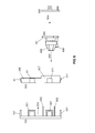
- FIGS. 1 to 5 show components of a front assembly according to an embodiment of the invention.
- the front module belongs to a built-in vehicle radio reception device, which in addition to the front module also has a rear assembly arranged behind the main assembly, which is surrounded by a housing.
- FIG. 1 shows the front panel 100 of the front assembly in a front view.
- the front panel 100 has the shape of a rectangle whose corners are rounded. Alternatively, the front panel may also have another shape, such as a trapezoidal shape.
- front 106 of the front panel 100 has a glossy surface.
- the front 106 is flat in the present case, but may alternatively be curved.
- the front side 106 may have a decorative element (not shown), for example a raised border, which stands out in color from the rest of the front side 106.
- the front panel 100 is provided with five recesses 101 to 105.
- the circular recesses 101 and 102 each have an operating element in the form of a rotary knob 405 (see FIG FIG. 4 ) take up.
- the rectangular recess 103 is intended to have a plurality of operating elements in the form of pushbuttons 406 (see FIG. 4 ) take up.
- the rectangular recess 104 is intended to be a display unit 407 (see FIG. 4 ) of the radio receiving device.
- the rectangular recess 105 is intended to receive the operating unit of the air conditioning system of the vehicle, so that the operating unit is framed by the front panel 100.
- the aforementioned rotary knobs 405, the aforementioned pushbuttons 406 and the aforementioned display unit 407 are mounted on a printed circuit board 400 (see FIG FIG. 4 ) attached.
- the front panel 100 can have further recesses, for example a recess for a further operating element, for inserting a storage medium or for connecting an external device.
- FIG. 2 shows the front panel 100 off FIG. 1 in a view from behind and in a side view.
- the front panel 100 has a plurality of U-shaped locking elements 201, which are arranged on the peripheral outer edge 206 of the front panel 100.
- Each of the latching elements 201 can with a latching element 311 of the support frame 300 (see FIG. 3 ) are latched so that the front panel 100 is attached to the support frame 300. Due to their arrangement on the outer edge 206 of the front panel 100, the latched locking elements 201 are accessible from outside the fully assembled front assembly, so that the locking elements 201 can be solved by the locking elements 311 without opening the front assembly.
- the front panel 100 has a plurality of cylindrical rod-shaped mounting pins 202, which are arranged in the lower region of the front panel 100, wherein the mounting pins 202 protrude almost vertically from the back of the front panel 100.
- the attachment pins 202 serve to secure portions of the bezel 100 spaced from the outer edge 206 to the support frame 300.
- the attachment posts 202 prevent the noted portions from undesirably protruding from the support frame or vibrating upon vibration of the vehicle.
- the areas mentioned are the webs 205, which are arranged between the recesses 103 and 104 or 104 and 105.
- the webs 205 are each provided with three attachment pins 202.
- the fixing pins 202 are used instead of locking elements to attach the webs 205 to the support frame 300. This is due to the fact that the Loosen fastening pins 202, in contrast to locking elements, even then, without opening the completely assembled front assembly, when they are spaced from the outer edge 206.
- latching elements 201 disposed on the outer edge 206 of the front panel 100 are combined with mounting posts 202 spaced from the outer edge 206 of the front panel 100 so that attachment of the front panel 100 to the support frame 300 can be solved without opening the fully assembled front module.
- the front panel 100 is integrally formed with the locking elements 201 and the mounting pins 202, so that the locking elements 201 and the mounting pins 202 have the same material as the rest of the front panel 100. This causes the front panel 100 can be produced inexpensively, the locking elements 201 and the fixing pins 202 are fixedly connected to the front panel 100.
- the material of the front panel 100 and the mounting pins 202 is thermoplastically deformable.
- the direction 204 is shown, in which the front panel 100 is mounted on the support frame 300 when mounting the front assembly.
- FIG. 3 shows the carrier frame 300 of the front assembly in a rear view and in a side view.
- the support frame 300 has the shape of a rectangle whose corners are rounded. Alternatively, however, the support frame may also have a different shape, for example a trapezoidal shape.
- the support frame 300 is provided with five recesses 301 to 305, which with the recesses 101 to 105 of the front panel 100 (see FIG. 1 ) correspond.
- the support frame 300 has a first side wall 307 surrounding the lower portion of the support frame 300.
- the first side wall 307 extends along the lower portion of the peripheral outer edge 306 of the support frame 300 and below the recess 305 along.
- the first side wall 307 has four reinforcements, each one are provided with a screw hole 309.
- the support frame 300 has a second side wall 308 extending along the upper portion of the outer edge 306. Both side walls, 307 and 308, protrude almost perpendicularly from the back of the support frame 300.
- the support frame 300 has a plurality of latching elements 311, which are arranged on the side walls 307 and 308 and with the latching elements 201 of the front panel 100 (see FIG. 2 ) correspond, so that the locking elements 201 of the front panel 100 can be latched with the locking elements 311 of the support frame 300.
- the locking elements 311 are each rectangular in shape and bevelled relative to the respective side wall 307 and 308, respectively.
- the support frame 300 has a plurality of circular holes 312, which with the mounting pins 202 of the front panel 100 (see FIG. 2 ), so that the fixing pins 202 can be passed through the holes 312.
- the support frame 300 is provided with a plurality of cylindrical rod-shaped spacers 313 which protrude almost perpendicularly from the rear side of the support frame 300.
- the spacers 313 serve to secure the circuit board 400 (see FIG. 4 ) in the carrier frame 300 in a predetermined position.
- each of the spacers 313 has a suitable height.
- each of the spacers 313 is provided with a screw hole disposed on its visible end face into which a fixing screw (not shown) can be screwed.
- the direction 314 is shown, from which the front panel 100 is mounted on the support frame 300 when mounting the front module. Further, the direction 315 is shown, from which the end plate 500 (see FIG. 5 ) is mounted on the support frame 300 when mounting the front assembly.
- FIG. 4 shows the printed circuit board 400 of the front assembly in a rear view and in a side view.
- the circuit board 400 has a rectangular basic shape and is formed so that it can be placed in the support frame 300, so that the circuit board 400 abuts against the spacers 313 and from the side wall 307 (see FIG. 3 ) is enclosed.
- the circuit board 400 has a plurality of circular holes 402, which with the mounting pins 202 of the front panel 100 (see FIG. 2 ) and the holes 312 of Carrier frame 300 (see FIG. 3 ), so that the fixing pins 202 can be passed through the holes 312 and 402.
- the above-mentioned knobs 405, push buttons 406 and the display unit 407 are attached, for example, glued or soldered.
- further electrical elements for example electronic components or printed conductors, can be arranged on the printed circuit board 400.
- FIG. 5 shows the end plate 500 of the front assembly in a view from behind and in a side view.
- the end plate 500 has the shape of a rectangle whose lower corners are rounded and whose upper corners run at right angles.
- the end plate 500 is further configured such that the side wall 307 including the area of the support frame 300 surrounded by the side wall 307 (see FIG FIG. 3 ) so that the front assembly is closed. This creates a surrounded by the support frame 300 and the end plate 500 closed interior, which can accommodate the circuit board 400.
- the end plate 500 is provided with a plurality of holes 502, which with the mounting pins 202 of the front panel 100 (see FIG. 2 ), the holes 312 of the support frame 300 and the holes 402 of the circuit board 400 correspond, so that the fixing pins 202 can be passed through the holes 502.
- the end plate 500 has a plurality of mounting holes 509 which are connected to the screw holes 309 of the support frame 300 (see FIG. 3 ) correspond.
- the holes 509 serve to fix the end plate 500 to the rear side of the support frame 300 by passing fastening screws (not shown) through the holes 509 and screwing them into the screw holes 309 of the support frame 300.
- the end plate 500 is provided with a recess 503 which serves to pass electrical lines extending from the main assembly of the radio receiving device into the front assembly.
- the end plate 500 has three Anschraublaschen 501, which protrude vertically from the back of the end plate 500 and serve to attach the front assembly to the housing of the main assembly.
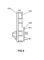
- FIG. 6 shows the front panel 100, the support frame 300, the circuit board 400 and the end plate 500 each in a side view to illustrate an embodiment of the method according to the invention for mounting a front assembly for a device or unit in a vehicle.
- FIG. 6 shown components of the front module provided.
- the circuit board 400 is inserted into the support frame 300 so that the holes 402 (see FIG FIG. 4 ) of the printed circuit board 400 with the holes 312 (see FIG. 3 ) of the support frame 300 and the mounting holes 413 (see FIG. 4 ) of the circuit board 400 with the screw holes of the spacers 313 (see FIG FIG. 3 ) of the support frame 300 are aligned.
- the circuit board 400 is inserted into the support frame 300 such that the circuit board is enclosed by the side wall 307 of the support frame 300 and the knobs 405 and push buttons 406 mounted on the circuit board 400 pass through the recesses 301 to 303 (see FIG FIG. 3 ) of the support frame 300.
- the printed circuit board 400 is moved in the direction 404 to the rear area of the carrier frame 300 enclosed by the side wall 307 until the printed circuit board 400 on the spacers 313 (see FIG FIG. 3 ) is present.
- the circuit board 400 is fixed to the support frame 300 by passing through each of the mounting holes 413 (see FIG. 4 ), a fastening screw (not shown) and into the screw hole of the associated spacer 313 (see FIG. 3 ) is screwed.
- the circuit board 400 may be attached to the support frame 300 in some other manner, such as by gluing or latching.
- the end plate 500 is attached to the back of the support frame 300 such that the holes 502 (see FIG FIG. 5 ) of the end plate 500 with the holes 312 (see FIG. 3 ) of the support frame 300 are aligned.
- the end plate 500 is placed in the direction 504 on the side wall 307 such that the end plate 500 covers the area enclosed by the side wall 307 portion of the support frame 300. In this way, an enclosed by the support frame 300 and the end plate 500 interior of the front assembly is formed, which receives the circuit board 400.
- the end plate can be attached to the support frame in another way, for example by gluing or by latching, for which corresponding locking elements would be provided. Notwithstanding this, it is also possible that the end plate is not attached to the support frame in the present method step, but only loosely arranged on the support frame.
- the front panel 100 is fastened to the front side of the support frame 300 by latching the latching elements 201 of the front panel 100 with the latching elements 311 of the support frame 300.
- the front panel 100 is placed in the direction 204 on the front side of the support frame 300, so that the mounting pins 202 of the front panel 100 through the holes 312 (see FIG. 3 ) of the support frame 300, the holes 402 (see FIG. 4 ) of the circuit board 400 and the holes 502 (see FIG. 5 ) of the end plate 500 are guided. In this way, a first attachment of the front panel 100 to the support frame 300 is made.
- the front panel 100 is only in the penultimate step of the method, so comparatively late, mounted. This has the advantage of reducing the risk of damaging the faceplate 100 during subsequent assembly steps as compared to a conventional frontal assembly.
- FIG. 7 shows a side view of the front assembly 700 after performing the fourth method step.
- the screws with which the end plate 500 has been attached to the support frame 300, are not shown for clarity.
- a mushroom-shaped thickening 801 (see FIG. 4) is hot-staked at the end of each fastening pin 202 guided through the end plate 500 FIG. 8 ), so that the end plate 500 on the support frame 300th is attached. That is, a second attachment of the end plate 500 to the support frame 300 is made. At the same time a second attachment of the front panel 100 is made to the support frame 300 so that. In other words, both the end plate 500 and the front panel 100 are secured to the support frame 300.
- the thickening 801 is formed such that the diameter of the thickening 801 is greater than the diameter of the associated hole 502 (see FIG. 5 ) of the end plate 500. In this way, it is ensured that the thickening 801 can not undesirably slide through the hole 502.
- the thickening may also have a different shape, for example pyramidal, conical, cylindrical or rivet-shaped. Further, the thickening may also be formed by a method other than hot caulking, for example by heat sealing.
- FIG. 8 shows a side view of the front assembly 700 after performing the fifth method step.
- the screws with which the end plate 500 has been attached to the support frame 300 are shown in FIG FIG. 8 not shown for a better overview.
- the thickenings 801 of the fastening pins 202 are removed, so that one of the two fastenings of the end plate 500 on the support frame 300 is released.
- one of the two fasteners of the front panel 100 is released on the support frame.
- To remove the thickenings 801 these are drilled.
- the latching elements 201 (see FIG. 2 ) of the front panel 100 of the locking elements 311 (see FIG. 3 ) of the support frame 300 is unlocked, so that a further attachment of the front panel 100 is solved on the support frame 300.
- the latching elements 201 and 311 can be unlocked manually, for example.
- the front panel 100 is removed from the support frame 300.
- the front panel 100 is pulled away from the front of the support frame such that the mounting pins 202 against the direction in which they Mount the front assembly in the holes 312 (see FIG. 3 ) and 402 (see FIG. 4 ) are withdrawn from said holes.
- the front panel 100 is detached from the front assembly 700 without opening the front assembly 700. This prevents the penetration of foreign objects into the interior of the front assembly when replacing the front panel 100.
- a new front panel can be mounted on the front assembly 700.
Landscapes
- Engineering & Computer Science (AREA)
- Mechanical Engineering (AREA)
- Chemical & Material Sciences (AREA)
- Combustion & Propulsion (AREA)
- Transportation (AREA)
- Casings For Electric Apparatus (AREA)
Abstract
Description
Die Erfindung betrifft eine Frontbaugruppe für ein Gerät oder Aggregat in einem Fahrzeug, ein Verfahren zum Montieren der Frontbaugruppe und ein Verfahren zum Demontieren der Frontbaugruppe.The invention relates to a front assembly for a device or aggregate in a vehicle, a method of mounting the front assembly, and a method of disassembling the front assembly.
Herkömmliche in Fahrzeugen eingebaute Geräte und Aggregate, beispielsweise Rundfunkempfangseinrichtungen, Navigationsgeräte, Radio-Navigationsgeräte, Klimaanlagen und Bordcomputer, verfügen jeweils über eine Frontblende, die vom Fahrzeuginnenraum zugänglich ist. Die Frontblende weist in der Regel eine Anzeigeeinheit, beispielsweise einen Bildschirm, und mehrere Bedienelemente, beispielsweise Druckschalter, Tasten, Drehschalter, Stufenschalter, Schiebeschalter oder Drehregler, auf. Während die Anzeigeeinheit zum Ausgeben von Informationen an einen Fahrzeugführer dient, ermöglichen die Bedienelemente eine manuelle Bedienung des jeweiligen Geräts oder Aggregats.Conventional in-vehicle devices and units, such as radio receivers, navigation devices, radio navigation devices, air conditioners and on-board computers, each have a front panel, which is accessible from the vehicle interior. The front panel usually has a display unit, such as a screen, and several controls, such as pressure switch, buttons, rotary switch, tap changer, slide switch or knob on. While the display unit is for outputting information to a driver, the controls allow for manual operation of the particular device or aggregate.
In letzter Zeit wurden viele in Fahrzeugen eingebaute Geräte und Aggregate mit Frontblenden ausgestattet, die aus Designgründen über Hochglanzoberflächen oder andere empfindliche Oberflächen verfügen. Solche Frontblenden sind besonders anfällig gegen mechanische Beschädigungen, beispielsweise in Form von Kratzern oder Dellen. Die Beschädigungen können insbesondere beim Montieren eines Geräts oder Aggregats oder bei seinem Einbau in ein Fahrzeug auftreten und einen Austausch der Frontblende erforderlich machen.Recently, many in-vehicle devices and gensets have been fitted with front panels that have high gloss surfaces or other delicate surfaces for design purposes. Such front panels are particularly susceptible to mechanical damage, for example in the form of scratches or dents. The damage may occur especially when mounting a device or aggregate or when installing it in a vehicle and require an exchange of the front panel.
Der Austausch der Frontblende ist jedoch aufwendig, da zu diesem Zweck das Gehäuse des Geräts oder Aggregats geöffnet werden muss, damit die Befestigungselemente gelöst werden können, mit denen die Frontblende an dem Gerät oder Aggregat befestigt ist. Erst dann kann die Frontblende abgenommen werden. Das hat den Nachteil zusätzlichen Aufwands. Daneben kann das Öffnen des Gehäuses zum Eindringen von Fremdkörpern, beispielsweise Schmutz, in das Gehäuseinnere führen, wodurch die ordnungsgemäße Funktion des Geräts oder Aggregats beeinträchtigt werden kann.The replacement of the front panel is complicated, since for this purpose the housing of the device or unit must be opened so that the fasteners can be solved with which the front panel is attached to the device or unit. Only then can the front panel be removed. This has the disadvantage of additional expense. In addition, the opening of the housing for the penetration of foreign objects, such as dirt, lead into the housing interior, whereby the proper operation of the device or unit can be affected.
Manche Geräte und Aggregate in einem Fahrzeug sind mit einer separaten Frontbaugruppe versehen. Eine derartige Frontbaugruppe ist durch eine lösbare Verbindung, beispielsweise eine Schraubverbindung, mit dem Gehäuse des Geräts oder Aggregats verbunden. Der Vorteil einer solchen Lösung besteht darin, dass zum Austauschen der Frontblende der Frontbaugruppe kein Öffnen des Gehäuses erforderlich ist. Dadurch wird ein Eindringen von Fremdkörpern in das Gehäuse beim Austauschen der Frontblende vermieden.Some devices and units in a vehicle are provided with a separate front module. Such a front assembly is connected by a releasable connection, such as a screw, with the housing of the device or unit. The advantage of such a solution is that it is not necessary to open the housing to replace the front bezel of the front assembly. This prevents foreign bodies from entering the housing when replacing the front panel.
Der Nachteil einer solchen Lösung besteht jedoch darin, dass das Austauschen der Frontblende ein Abnehmen der Frontbaugruppe von dem Gehäuse und ein Öffnen der Frontbaugruppe erfordert, sodass der Innenraum der Frontbaugruppe zugänglich wird. Das ist notwendig, damit die Befestigungselemente gelöst werden können, mit denen die Frontblende an der Frontbaugruppe befestigt ist. Dadurch entsteht zusätzlicher Aufwand. Daneben kann das Öffnen der Frontbaugruppe zum Eindringen von Fremdkörpern, beispielsweise Schmutz, in die Frontbaugruppe führen, wodurch die ordnungsgemäße Funktion der Frontbaugruppe beeinträchtigt werden kann.However, the disadvantage of such a solution is that replacing the front panel requires detaching the front assembly from the chassis and opening the front assembly so that the interior of the front assembly becomes accessible. This is necessary to release the fasteners that secure the front bezel to the front panel assembly. This creates additional expense. In addition, opening the front assembly, such as debris, into the front assembly may result in the ingress of foreign objects, which may affect the proper operation of the front assembly.
Ein weiterer Nachteil einer separat vom Gehäuse eines Geräts oder Aggregats angeordneten Frontbaugruppe besteht darin, dass beim Montieren der Frontbaugruppe die Frontblende angebracht werden muss, solange der Innenraum der Frontbaugruppe noch von außen zugänglich ist. Das ist notwendig, damit die Frontblende im Innenraum der Frontbaugruppe befestigt werden kann. Deshalb muss die Frontblende in einem vergleichsweise frühen Stadium des Montageprozesses angebracht werden, insbesondere bevor die Frontbaugruppe verschlossen wird. Das führt dazu, dass die Frontblende bei einer großen Anzahl nachfolgender Montagesschritte mitgeführt werden muss, sodass ein hohes Risiko besteht, die Oberfläche der Frontblende während des Montageprozesses zu beschädigen.Another disadvantage of a separate front of the housing of a device or unit front assembly is that when mounting the front module, the front panel must be installed as long as the interior of the front module is still accessible from the outside. This is necessary so that the front panel can be mounted in the interior of the front assembly. Therefore, the front panel must be installed at a relatively early stage of the assembly process, especially before the front assembly is closed. As a result, the front panel must be carried along with a large number of subsequent assembly steps, so that there is a high risk of damaging the surface of the front panel during the assembly process.
Daher stellt sich die Aufgabe, eine Frontbaugruppe für ein Gerät oder Aggregat in einem Fahrzeug bereitzustellen, welche derart ausgebildet ist, dass das Risiko eines Beschädigens der Frontblende der Frontbaugruppe beim Montieren der Frontbaugruppe vermindert wird. Ferner soll die Frontbaugruppe derart ausgebildet sein, dass die Frontblende mit geringem Aufwand austauschbar ist. Dabei soll das Risiko des Eindringens von Fremdkörpern in das Innere der Frontbaugruppe beim Austauschen der Frontblende niedrig sein.Therefore, the object is to provide a front assembly for a device or aggregate in a vehicle, which is designed such that the risk of damaging the front panel of the front assembly is reduced when mounting the front assembly. Furthermore, the front module should be designed such that the front panel is interchangeable with little effort. The risk of foreign material entering the interior of the front panel when replacing the front panel should be low.
Die Aufgabe wird mit der Frontbaugruppe für ein Gerät oder Aggregat in einem Fahrzeug gemäß der Erfindung gelöst. Die Frontbaugruppe weist folgende Bestandteile auf:
- (a) einen Trägerrahmen mit einem ersten Rastelement und einem ersten Loch,
- (b) eine in dem Trägerrahmen angeordnete Leiterplatte mit einem Bedienelement oder einer Anzeigeeinheit und einem zweiten Loch,
- (c) ein an der Rückseite des Trägerrahmens befestigtes Abschlussblech mit einem dritten Loch und
- (d) eine an der Vorderseite des Trägerrahmens angeordnete Frontblende mit einem zweiten Rastelement und einem Befestigungsstift, welcher durch das erste Loch, das zweite Loch und das dritte Loch geführt ist.
- (a) a support frame having a first latching element and a first hole,
- (b) a circuit board arranged in the support frame with a control element or a display unit and a second hole,
- (c) a cover plate fastened to the back of the support frame with a third hole and
- (D) a arranged at the front of the support frame front panel with a second locking element and a fixing pin, which is guided through the first hole, the second hole and the third hole.
Das erste Rastelement ist mit dem zweiten Rastelement verrastet, sodass die Frontblende an dem Trägerrahmen befestigt ist. Ferner weist der Befestigungsstift der Frontblende eine an der Rückseite des Abschlussblechs angeordnete Verdickung auf, sodass eine zusätzliche Befestigung der Frontblende an dem Trägerrahmen ausgebildet ist.The first latching element is latched to the second latching element, so that the front panel is attached to the support frame. Furthermore, the fastening pin of the front panel has a thickening arranged on the rear side of the end plate, so that an additional fastening of the front panel to the carrier frame is formed.
Folglich verläuft der Befestigungsstift ausgehend von der Frontblende durch den Trägerrahmen, die Leiterplatte und das Abschlussblech. Dadurch ist das Ende des Befestigungsstifts an der Rückseite des Abschlussblechs, also von außen, zugänglich. Deshalb kann die Frontbaugruppe beim Montieren der Frontblende bereits durch das Abschlussblech geschlossen sein. Das hat den Vorteil, dass die Frontblende am Ende des Montageprozesses an der Frontbaugruppe angebracht werden kann. Somit ist das Risiko einer Beschädigung der Frontblende während des Montageprozesses im Vergleich zu einer herkömmlichen Frontbaugruppe vermindert.Consequently, the fastening pin extends from the front panel through the support frame, the circuit board and the end plate. As a result, the end of the fastening pin on the back of the end plate, so from the outside, accessible. Therefore, the front module may already be closed by the end plate when mounting the front panel. This has the advantage that the front panel can be attached to the front panel at the end of the assembly process. Thus, the risk of damaging the bezel during the assembly process is reduced as compared to a conventional front assembly.
Des Weiteren ermöglicht die Erfindung ein einfaches Austauschen der Frontblende der fertig montierten Frontbaugruppe. Dazu wird die Frontbaugruppe gegebenenfalls vom Gehäuse des Geräts oder Aggregats abgenommen, um die Verdickung des Befestigungsstifts auf der Rückseite des Abschlussblechs zugänglich zu machen. Dann wird die Verdickung entfernt, beispielsweise aufgebohrt, sodass eine der beiden Befestigungen der Frontblende an dem Trägerrahmen gelöst wird. Danach wird das zweite Rastelement von dem ersten Rastelement entrastet, sodass die andere Befestigung der Frontblende an dem Trägerrahmen gelöst wird. Anschließend lässt sich die Frontblende von der Frontbaugruppe abnehmen.Furthermore, the invention allows for easy replacement of the front panel of the fully assembled front assembly. If necessary, remove the front assembly from the unit or genset housing to expose the thickening of the mounting pin on the back of the end plate. Then the thickening is removed, for example, drilled so that one of the two fasteners of the front panel is solved on the support frame. Thereafter, the second locking element is unlocked by the first locking element, so that the other attachment of the front panel is solved on the support frame. Then the front panel can be removed from the front module.
Zum Montieren der neuen Frontblende wird diese auf die Vorderseite des Trägerrahmens aufgesetzt, wobei das zweite Rastelement mit dem ersten Rastelement verrastet wird und der Befestigungsstift durch das erste Loch, das zweite Loch und das dritte Loch geführt wird. Anschließend wird an dem Ende des Befestigungsstifts der neuen Frontblende, das aus der Rückseite des Abschlussblechs herausragt, eine neue Verdickung ausgebildet, sodass eine zusätzliche Befestigung der Frontblende an dem Trägerrahmen hergestellt wird.To mount the new front panel is placed on the front of the support frame, wherein the second locking element is locked with the first locking element and the fixing pin is passed through the first hole, the second hole and the third hole. Subsequently, a new thickening is formed at the end of the mounting pin of the new front panel, which protrudes from the back of the end plate, so that an additional attachment of the front panel is made to the support frame.
Mit der beschriebenen Verfahrensweise kann die Frontblende mit besonders geringem Aufwand ausgetauscht werden, wobei kein Öffnen der Frontbaugruppe erforderlich ist, sodass keine Fremdkörper in die Frontbaugruppe eindringen können.With the described procedure, the front panel can be replaced with very little effort, with no opening of the front module is required, so that no foreign body can penetrate into the front module.
Neben der erfindungsgemäßen Frontbaugruppe wird auch ein Verfahren zum Montieren der Frontbaugruppe bereitgestellt, welches folgende Schritte aufweist:
- (1) Bereitstellen eines Trägerrahmens mit einem ersten Rastelement und einem ersten Loch, einer Leiterplatte mit einem Bedienelement oder einer Anzeigeeinheit und einem zweiten Loch, eines Abschlussblechs mit einem dritten Loch und einer Frontblende mit einem zweiten Rastelement und einem Befestigungsstift,
- (2) Einsetzen der Leiterplatte in den Trägerrahmen, sodass das zweite Loch mit dem ersten Loch fluchtet,
- (3) Befestigen des Abschlussblechs an der Rückseite des Trägerrahmens, sodass das dritte Loch mit dem ersten Loch fluchtet,
- (4) Befestigen der Frontblende an der Vorderseite des Trägerrahmens, indem der Befestigungsstift durch das erste Loch, das zweite Loch und das dritte Loch geführt wird und das erste Rastelement mit dem zweiten Rastelement verrastet wird,
- (5) Ausbilden einer an der Rückseite des Abschlussblechs angeordneten Verdickung des Befestigungsstifts, sodass eine zusätzliche Befestigung der Frontblende an dem Trägerrahmen hergestellt wird.
- (1) providing a support frame having a first latching element and a first hole, a circuit board having a control or display unit and a second hole, a cover plate having a third hole and a front panel having a second latching element and a fixing pin,
- (2) inserting the circuit board into the support frame so that the second hole is aligned with the first hole,
- (3) attach the end plate to the back of the carrier frame so that the third hole aligns with the first hole,
- (4) attaching the front panel to the front side of the support frame by passing the fixing pin through the first hole, the second hole and the third hole, and latching the first latching member with the second latching member;
- (5) forming a thickening of the mounting pin located at the rear of the end plate so that additional attachment of the front cover to the support frame is made.
Des Weiteren wird ein Verfahren zum Demontieren der obigen Frontbaugruppe bereitgestellt, welches die folgenden Schritte aufweist:
- (1) Entfernen der Verdickung, sodass eine Befestigung der Frontblende an dem Trägerrahmen gelöst wird,
- (2) Entrasten des zweiten Rastelements von dem ersten Rastelement, sodass eine weitere Befestigung der Frontblende an dem Trägerrahmen gelöst wird, und
- (3) Abnehmen der Frontblende von dem Trägerrahmen, sodass der Befestigungsstift aus dem ersten Loch herausgezogen wird.
- (1) removing the thickening so that attachment of the front panel to the support frame is released,
- (2) unlatching of the second latching element of the first latching element, so that a further attachment of the front panel is solved on the support frame, and
- (3) Remove the bezel from the carrier frame so that the attachment pin is pulled out of the first hole.
Weitere Ausführungsformen der Erfindung sind in den abhängigen Patentansprüchen beschrieben.Further embodiments of the invention are described in the dependent claims.
Im Folgenden wird die Erfindung anhand von Figuren weiter erläutert, welche Folgendes darstellen:
-
Figur 1 zeigt die Frontblende einer Frontbaugruppe gemäß einer Ausführungsform der Erfindung in einer Ansicht von vorn. -
Figur 2 zeigt die Frontblende ausFigur 1 in einer Ansicht von hinten und in einer Seitenansicht. -
Figur 3 zeigt den Trägerrahmen der Frontbaugruppe in einer Ansicht von hinten und in einer Seitenansicht. -
Figur 4 zeigt die Leiterplatte der Frontbaugruppe in einer Ansicht von hinten und in einer Seitenansicht. -
Figur 5 zeigt das Abschlussblech der Frontbaugruppe in einer Ansicht von hinten und in einer Seitenansicht. -
Figur 6 zeigt die Frontblende, den Trägerrahmen, die Leiterplatte und das Abschlussblech jeweils in einer Seitenansicht, zur Verdeutlichung einer Ausführungsform des erfindungsgemäßen Verfahrens zum Montieren der Frontbaugruppe.
-
FIG. 1 shows the front panel of a front assembly according to an embodiment of the invention in a front view. -
FIG. 2 shows the front panelFIG. 1 in a view from behind and in a side view. -
FIG. 3 shows the support frame of the front assembly in a view from behind and in a side view. -
FIG. 4 shows the PCB of the front module in a view from behind and in a side view. -
FIG. 5 shows the end plate of the front assembly in a view from behind and in a side view. -
FIG. 6 shows the front panel, the support frame, the circuit board and the end plate in each case in a side view, to illustrate an embodiment of the method according to the invention for mounting the front module.
Die
Im Folgenden wird zunächst auf die
Die Frontblende 100 hat die Form eines Rechtecks, dessen Ecken abgerundet sind. Alternativ dazu kann die Frontblende auch eine andere Form aufweisen, beispielsweise ein Trapezform.The
Die in
Ferner ist die Frontblende 100 mit fünf Aussparungen 101 bis 105 versehen. Die kreisrunden Aussparungen 101 und 102 sollen jeweils ein Bedienelement in Form eines Drehknopfs 405 (siehe
Zusätzlich zu den Aussparungen 101 bis 105 kann die Frontblende 100 weitere Aussparungen aufweisen, beispielsweise eine Aussparung für ein weiteres Bedienelement, zum Einschieben eines Speichermediums oder zum Anschließen eines externen Geräts.In addition to the
Die Frontblende 100 weist mehrere U-förmige Rastelemente 201 auf, die an dem umlaufenden Außenrand 206 der Frontblende 100 angeordnet sind. Jedes der Rastelemente 201 kann mit einem Rastelement 311 des Trägerrahmens 300 (siehe
Außerdem weist die Frontblende 100 mehrere zylinderstabförmige Befestigungsstifte 202 auf, welche im unteren Bereich der Frontblende 100 angeordnet sind, wobei die Befestigungsstifte 202 nahezu senkrecht aus der Rückseite der Frontblende 100 ragen. Die Befestigungsstifte 202 dienen zum Befestigen von Bereichen der Frontblende 100, die vom Außenrand 206 beabstandet sind, an dem Trägerrahmen 300. Die Befestigungsstifte 202 verhindern, dass die genannten Bereiche in unerwünschter Weise von dem Trägerrahmen abstehen oder bei Vibrationen des Fahrzeugs schwingen.In addition, the
Im vorliegenden Fall handelt es sich bei den genannten Bereichen um die Stege 205, welche zwischen den Aussparungen 103 und 104 beziehungsweise 104 und 105 angeordnet sind. Die Stege 205 sind mit jeweils drei Befestigungsstiften 202 versehen.In the present case, the areas mentioned are the
Demzufolge werden anstelle von Rastelementen die Befestigungsstifte 202 eingesetzt, um die Stege 205 an dem Trägerrahmen 300 zu befestigen. Das ist darin begründet, dass sich die Befestigungsstifte 202 im Gegensatz zu Rastelementen auch dann lösen lassen, ohne die fertig montierte Frontbaugruppe zu öffnen, wenn sie vom Außenrand 206 beabstandet sind.Accordingly, the fixing pins 202 are used instead of locking elements to attach the
Zusammenfassend werden zum Befestigen der Frontblende 100 an dem Trägerrahmen 300 Rastelemente 201, die am Außenrand 206 der Frontblende 100 angeordnet sind, mit Befestigungsstiften 202 kombiniert, die vom Außenrand 206 der Frontblende 100 beabstandet sind, sodass sich die Befestigung der Frontblende 100 an dem Trägerrahmen 300 lösen lässt, ohne die fertig montierte Frontbaugruppe zu öffnen.In summary, for attaching the
Gemäß einer anderen Ausführungsform der Erfindung sind weitere Bereiche der Frontblende, die vom Außenrand beabstandet sind, mit Befestigungsstiften versehen, beispielsweise die Umgebungsbereiche von Aussparungen.According to another embodiment of the invention, further areas of the front panel, which are spaced from the outer edge, provided with mounting pins, for example, the surrounding areas of recesses.
Die Frontblende 100 ist mit den Rastelementen 201 und den Befestigungsstiften 202 einstückig ausgebildet, sodass die Rastelemente 201 und die Befestigungsstifte 202 das gleiche Material aufweisen, wie der Rest der Frontblende 100. Das bewirkt, dass die Frontblende 100 kostengünstig hergestellt werden kann, wobei die Rastelemente 201 und die Befestigungsstifte 202 fest mit der Frontblende 100 verbunden sind. Das Material der Frontblende 100 beziehungsweise der Befestigungsstifte 202 ist thermoplastisch verformbar.The
Des Weiteren ist die Richtung 204 gezeigt, in welcher die Frontblende 100 bei dem Montieren der Frontbaugruppe auf den Trägerrahmen 300 aufgesetzt wird.Furthermore, the
Der Trägerrahmen 300 hat die Form eines Rechtecks, dessen Ecken abgerundet sind. Alternativ dazu kann der Trägerrahmen aber auch eine andere Form aufweisen, beispielsweise eine Trapezform. Der Trägerrahmen 300 ist mit fünf Aussparungen 301 bis 305 versehen, welche mit den Aussparungen 101 bis 105 der Frontblende 100 (siehe
Außerdem verfügt der Trägerrahmen 300 über eine erste Seitenwand 307, welche den unteren Bereich des Trägerrahmens 300 umgibt. Dazu verläuft die erste Seitenwand 307 entlang des unteren Abschnitts des umlaufenden Außenrands 306 des Trägerrahmens 300 und unter der Aussparung 305 entlang. Die erste Seitenwand 307 weist vier Verstärkungen auf, die jeweils mit einem Schraubloch 309 versehen sind. Zusätzlich verfügt der Trägerrahmen 300 über eine zweite Seitenwand 308, welche entlang des oberen Abschnitts des Außenrands 306 verläuft. Beide Seitenwände, 307 und 308, ragen nahezu senkrecht aus der Rückseite des Trägerrahmens 300.In addition, the
Ferner weist der Trägerrahmen 300 mehrere Rastelemente 311 auf, welche auf den Seitenwänden 307 und 308 angeordnet sind und mit den Rastelementen 201 der Frontblende 100 (siehe
Weiterhin verfügt der Trägerrahmen 300 über mehrere kreisrunde Löcher 312, welche mit den Befestigungsstiften 202 der Frontblende 100 (siehe
Des Weiteren ist die Richtung 314 dargestellt, aus welcher die Frontblende 100 beim Montieren der Frontbaugruppe auf den Trägerrahmen 300 aufgesetzt wird. Ferner ist die Richtung 315 gezeigt, aus welcher das Abschlussblech 500 (siehe
Die Leiterplatte 400 hat eine rechteckförmige Grundform und ist derart ausgebildet, dass sie in dem Trägerrahmen 300 platziert werden kann, sodass die Leiterplatte 400 an den Abstandshaltern 313 anliegt und von der Seitenwand 307 (siehe
Das Abschlussblech 500 hat die Form eines Rechtecks, dessen untere Ecken abgerundet sind und dessen obere Ecken rechtwinklig zulaufen. Das Abschlussblech 500 ist ferner derart ausgebildet, dass sich damit die Seitenwand 307 inklusive des von der Seitenwand 307 umgebenen Bereichs des Trägerrahmens 300 (siehe
Des Weiteren ist das Abschlussblech 500 mit mehreren Löchern 502 versehen, welche mit den Befestigungsstiften 202 der Frontblende 100 (siehe
Außerdem weist das Abschlussblech 500 mehrere Befestigungslöcher 509 auf, die mit den Schraublöchern 309 des Trägerrahmens 300 (siehe
Ferner ist das Abschlussblech 500 mit einer Aussparung 503 versehen, welche zum Durchführen elektrischer Leitungen dient, die von der Hauptbaugruppe der Rundfunkempfangseinrichtung in die Frontbaugruppe verlaufen. Daneben verfügt das Abschlussblech 500 über drei Anschraublaschen 501, welche senkrecht aus der Rückseite des Abschlussblechs 500 ragen und zum Befestigen der Frontbaugruppe an dem Gehäuse der Hauptbaugruppe dienen.Further, the
Bei einem ersten Verfahrensschritt werden die in
Bei einem zweiten Verfahrensschritt wird die Leiterplatte 400 in den Trägerrahmen 300 eingesetzt, sodass die Löcher 402 (siehe
Dann wird die Leiterplatte 400 an dem Trägerrahmen 300 befestigt, indem durch jedes der Befestigungslöcher 413 (siehe
Bei einem dritten Verfahrensschritt wird das Abschlussblech 500 so an der Rückseite des Trägerrahmens 300 befestigt, dass die Löcher 502 (siehe
Dann wird durch jedes der Befestigungslöcher 509 (siehe
Alternativ dazu kann das Abschlussblech auch auf eine andere Weise an dem Trägerrahmen befestigt werden, beispielsweise durch Verkleben oder durch Verrasten, wofür entsprechende Rastelemente vorgesehen wären. Abweichend davon ist es auch möglich, dass das Abschlussblech bei dem vorliegenden Verfahrensschritt nicht auf dem Trägerrahmen befestigt, sondern nur lose auf dem Trägerrahmen angeordnet wird.Alternatively, the end plate can be attached to the support frame in another way, for example by gluing or by latching, for which corresponding locking elements would be provided. Notwithstanding this, it is also possible that the end plate is not attached to the support frame in the present method step, but only loosely arranged on the support frame.
Bei einem vierten Verfahrensschritt wird die Frontblende 100 an der Vorderseite des Trägerrahmens 300 befestigt, indem die Rastelemente 201 der Frontblende 100 mit den Rastelementen 311 des Trägerrahmens 300 verrastet werden. Dazu wird die Frontblende 100 in Richtung 204 auf die Vorderseite des Trägerrahmens 300 aufgesetzt, sodass die Befestigungsstifte 202 der Frontblende 100 durch die Löcher 312 (siehe
Damit wird die Frontblende 100 erst im vorletzten Schritt des erfindungsgemäßen Verfahrens, also vergleichsweise spät, montiert. Das hat den Vorteil, dass das Risiko eines Beschädigens der Frontblende 100 während folgender Montageschritte im Vergleich zu einer herkömmlichen Frontbaugruppe vermindert ist.Thus, the
Bei einem fünften Verfahrensschritt wird an dem durch das Abschlussblech 500 geführten Ende jedes Befestigungsstifts 202 durch Heißverstemmen eine pilzkopfförmige Verdickung 801 (siehe
Alternativ zu der genannten Pilzkopfform kann die Verdickung auch eine andere Form aufweisen, beispielsweise pyramidenförmig, kegelförmig, zylinderförmig oder nietenförmig sein. Ferner kann die Verdickung auch durch ein anderes Verfahren als Heißverstemmen ausgebildet werden, beispielsweise durch Heißversiegeln.As an alternative to the said mushroom head shape, the thickening may also have a different shape, for example pyramidal, conical, cylindrical or rivet-shaped. Further, the thickening may also be formed by a method other than hot caulking, for example by heat sealing.
Im Folgenden wird eine Ausführungsform des erfindungsgemäßen Verfahrens zum Demontieren der in
Bei einem ersten Verfahrensschritt werden die Verdickungen 801 der Befestigungsstifte 202 entfernt, sodass eine der beiden Befestigungen des Abschlussblechs 500 an dem Trägerrahmen 300 gelöst wird. Damit wird auch eine der beiden Befestigungen der Frontblende 100 an dem Trägerrahmen gelöst. Zum Entfernen der Verdickungen 801 werden diese aufgebohrt. Es ist jedoch auch möglich, die Verdickungen 801 auf eine andere Art zu entfernen, beispielsweise durch Abschneiden oder durch thermisches Verformen.In a first method step, the
Bei einem zweiten Verfahrensschritt werden die Rastelemente 201 (siehe
Bei einem dritten Verfahrensschritt wird die Frontblende 100 von dem Trägerrahmen 300 abgenommen. Dazu wird die Frontblende 100 derart von der Vorderseite des Trägerrahmens weggezogen, dass die Befestigungsstifte 202 entgegen der Richtung, in welche sie beim Montieren der Frontbaugruppe in die Löcher 312 (siehe
Damit wird die Frontblende 100 von der Frontbaugruppe 700 abgenommen, ohne die Frontbaugruppe 700 zu öffnen. Dadurch wird ein Eindringen von Fremdkörpern in den Innenraum der Frontbaugruppe beim Austauschen der Frontblende 100 vermieden.Thus, the
Anschließend kann eine neue Frontblende auf der Frontbaugruppe 700 montiert werden.Subsequently, a new front panel can be mounted on the
Claims (10)
wobei das zweite Rastelement (201) an einem Außenrand (206) der Frontblende (100) angeordnet ist und der Befestigungsstift (202) von dem Außenrand (206) beabstandet ist.Front assembly (700) according to claim 1,
wherein the second detent member (201) is disposed on an outer edge (206) of the front panel (100) and the attachment pin (202) is spaced from the outer edge (206).
wobei der Befestigungsstift (202) auf einem Steg (205) der Frontblende (100) angeordnet ist.Front assembly (700) according to claim 2,
wherein the fastening pin (202) is arranged on a web (205) of the front panel (100).
wobei die Verdickung (801) pilzkopfförmig, pyramidenförmig, kegelförmig, zylinderförmig oder nietenförmig ausgebildet ist.Front assembly (700) according to one of the preceding claims,
wherein the thickening (801) is mushroom-shaped, pyramidal, conical, cylindrical or rivet-shaped.
wobei der Trägerrahmen (300) und die Frontblende (100) die Bedieneinheit eines weiteren Geräts oder Aggregats in dem Fahrzeug umrahmen.Front assembly (700) according to one of the preceding claims,
wherein the carrier frame (300) and the front panel (100) frame the operating unit of another device or aggregate in the vehicle.
wobei das weitere Gerät oder Aggregat an dem Trägerrahmen (300) befestigt ist.Front assembly (700) according to claim 5,
wherein the further device or unit is attached to the support frame (300).
bei dem die Verdickung (801) durch Heißverstemmen oder Heißversiegeln ausgebildet wird.Method according to claim 7,
wherein the thickening (801) is formed by heat staking or heat sealing.
bei dem die Verdickung (801) durch Aufbohren zerstört wird.Method according to claim 9,
in which the thickening (801) is destroyed by drilling.
Applications Claiming Priority (1)
| Application Number | Priority Date | Filing Date | Title |
|---|---|---|---|
| DE102011089901A DE102011089901B3 (en) | 2011-12-23 | 2011-12-23 | Front assembly for a device or aggregate in a vehicle |
Publications (2)
| Publication Number | Publication Date |
|---|---|
| EP2608647A1 true EP2608647A1 (en) | 2013-06-26 |
| EP2608647B1 EP2608647B1 (en) | 2013-12-11 |
Family
ID=47561199
Family Applications (1)
| Application Number | Title | Priority Date | Filing Date |
|---|---|---|---|
| EP12198861.2A Active EP2608647B1 (en) | 2011-12-23 | 2012-12-21 | Front assembly for a device or unit in a vehicle |
Country Status (2)
| Country | Link |
|---|---|
| EP (1) | EP2608647B1 (en) |
| DE (1) | DE102011089901B3 (en) |
Citations (3)
| Publication number | Priority date | Publication date | Assignee | Title |
|---|---|---|---|---|
| US4068175A (en) * | 1975-10-24 | 1978-01-10 | Boman Industries | Detachable cover member for car radios and the like |
| US20030141738A1 (en) * | 2002-01-31 | 2003-07-31 | Britta Straesser | Automobile instrument panel assembly |
| US20030146350A1 (en) * | 2002-02-06 | 2003-08-07 | Autonetworks Technologies, Ltd. | Attachment structure for a center display unit |
Family Cites Families (2)
| Publication number | Priority date | Publication date | Assignee | Title |
|---|---|---|---|---|
| DE4309336C1 (en) * | 1993-03-17 | 1994-06-23 | Mannesmann Ag | Electronic device for switch panel or control console |
| DE29823810U1 (en) * | 1998-03-20 | 1999-12-23 | Whirlpool Co | Control panel for a household appliance |
-
2011
- 2011-12-23 DE DE102011089901A patent/DE102011089901B3/en not_active Expired - Fee Related
-
2012
- 2012-12-21 EP EP12198861.2A patent/EP2608647B1/en active Active
Patent Citations (3)
| Publication number | Priority date | Publication date | Assignee | Title |
|---|---|---|---|---|
| US4068175A (en) * | 1975-10-24 | 1978-01-10 | Boman Industries | Detachable cover member for car radios and the like |
| US20030141738A1 (en) * | 2002-01-31 | 2003-07-31 | Britta Straesser | Automobile instrument panel assembly |
| US20030146350A1 (en) * | 2002-02-06 | 2003-08-07 | Autonetworks Technologies, Ltd. | Attachment structure for a center display unit |
Also Published As
| Publication number | Publication date |
|---|---|
| EP2608647B1 (en) | 2013-12-11 |
| DE102011089901B3 (en) | 2013-06-13 |
Similar Documents
| Publication | Publication Date | Title |
|---|---|---|
| DE112015004363B4 (en) | STRUCTURE FOR FASTENING ON-BOARD EQUIPMENT | |
| DE102008046983A1 (en) | Vehicle interior illumination lamp unit | |
| DE102012021986B4 (en) | Stand centrifuge in modular design | |
| DE10242467A1 (en) | Device for housing an electrical device in the interior of a motor vehicle | |
| DE102007021834A1 (en) | Switching device of a motor vehicle and assembly method thereof | |
| EP1470025B1 (en) | Electrical appliance to be mounted on a retainer | |
| EP2608647B1 (en) | Front assembly for a device or unit in a vehicle | |
| DE10227562B4 (en) | Cover frame for an electrical installation device | |
| EP1715545A1 (en) | Apparatus for mounting an antenna to a vehicle | |
| EP2609799B1 (en) | Closure system for subassemblies and assembly method | |
| DE60036130T2 (en) | DISPLAY DEVICE AND FRAMEWORK FOR SUCH A | |
| DE102018108307A1 (en) | Door handle assembly for a vehicle | |
| DE69820163T2 (en) | Two-media assembly holding device for a motor vehicle | |
| DE60223782T2 (en) | Combination of front panels | |
| EP1927481A1 (en) | Component holder | |
| DE102020107646B4 (en) | Computer and method for specifying an expansion card in a computer | |
| DE102005026016A1 (en) | Loudspeaker for use in motor vehicle door, has diaphragm retainer and console, where fastening units at retainer side cooperate with fastening units at console side for forming positive fastening of diaphragm retainer at console | |
| EP2518902B1 (en) | Operating section for a motor vehicle | |
| DE69909540T2 (en) | Vehicle control panel with printed circuit | |
| DE102018127396B4 (en) | Screen module, module and method for expanding a signal feed | |
| DE102015010295A1 (en) | Display device for a motor vehicle | |
| EP1402480A2 (en) | Means for connecting a front panel of a parallelepipedal built-in unit to the built-in housing of the latter | |
| CH716994B1 (en) | Fastening system and fastening method for an electrical installation apparatus. | |
| DE102022004429A1 (en) | Retaining plate | |
| DE102021117006A1 (en) | Heads-up display device for a motor vehicle and method for manufacturing a heads-up display device |
Legal Events
| Date | Code | Title | Description |
|---|---|---|---|
| AK | Designated contracting states |
Kind code of ref document: A1 Designated state(s): AL AT BE BG CH CY CZ DE DK EE ES FI FR GB GR HR HU IE IS IT LI LT LU LV MC MK MT NL NO PL PT RO RS SE SI SK SM TR |
|
| AX | Request for extension of the european patent |
Extension state: BA ME |
|
| PUAI | Public reference made under article 153(3) epc to a published international application that has entered the european phase |
Free format text: ORIGINAL CODE: 0009012 |
|
| 17P | Request for examination filed |
Effective date: 20130725 |
|
| RBV | Designated contracting states (corrected) |
Designated state(s): AL AT BE BG CH CY CZ DE DK EE ES FI FR GB GR HR HU IE IS IT LI LT LU LV MC MK MT NL NO PL PT RO RS SE SI SK SM TR |
|
| GRAP | Despatch of communication of intention to grant a patent |
Free format text: ORIGINAL CODE: EPIDOSNIGR1 |
|
| RIC1 | Information provided on ipc code assigned before grant |
Ipc: B60K 35/00 20060101ALI20130809BHEP Ipc: B60K 37/06 20060101ALI20130809BHEP Ipc: B60K 37/04 20060101ALI20130809BHEP Ipc: B60R 11/02 20060101ALI20130809BHEP Ipc: B60R 11/00 20060101ALN20130809BHEP Ipc: H05K 7/14 20060101AFI20130809BHEP |
|
| INTG | Intention to grant announced |
Effective date: 20130918 |
|
| GRAS | Grant fee paid |
Free format text: ORIGINAL CODE: EPIDOSNIGR3 |
|
| GRAA | (expected) grant |
Free format text: ORIGINAL CODE: 0009210 |
|
| AK | Designated contracting states |
Kind code of ref document: B1 Designated state(s): AL AT BE BG CH CY CZ DE DK EE ES FI FR GB GR HR HU IE IS IT LI LT LU LV MC MK MT NL NO PL PT RO RS SE SI SK SM TR |
|
| REG | Reference to a national code |
Ref country code: GB Ref legal event code: FG4D Free format text: NOT ENGLISH |
|
| REG | Reference to a national code |
Ref country code: CH Ref legal event code: EP |
|
| REG | Reference to a national code |
Ref country code: AT Ref legal event code: REF Ref document number: 645145 Country of ref document: AT Kind code of ref document: T Effective date: 20140115 |
|
| REG | Reference to a national code |
Ref country code: IE Ref legal event code: FG4D Free format text: LANGUAGE OF EP DOCUMENT: GERMAN |
|
| REG | Reference to a national code |
Ref country code: DE Ref legal event code: R096 Ref document number: 502012000261 Country of ref document: DE Effective date: 20140206 |
|
| REG | Reference to a national code |
Ref country code: NL Ref legal event code: VDEP Effective date: 20131211 |
|
| PG25 | Lapsed in a contracting state [announced via postgrant information from national office to epo] |
Ref country code: SE Free format text: LAPSE BECAUSE OF FAILURE TO SUBMIT A TRANSLATION OF THE DESCRIPTION OR TO PAY THE FEE WITHIN THE PRESCRIBED TIME-LIMIT Effective date: 20131211 Ref country code: NO Free format text: LAPSE BECAUSE OF FAILURE TO SUBMIT A TRANSLATION OF THE DESCRIPTION OR TO PAY THE FEE WITHIN THE PRESCRIBED TIME-LIMIT Effective date: 20140311 Ref country code: HR Free format text: LAPSE BECAUSE OF FAILURE TO SUBMIT A TRANSLATION OF THE DESCRIPTION OR TO PAY THE FEE WITHIN THE PRESCRIBED TIME-LIMIT Effective date: 20131211 Ref country code: LT Free format text: LAPSE BECAUSE OF FAILURE TO SUBMIT A TRANSLATION OF THE DESCRIPTION OR TO PAY THE FEE WITHIN THE PRESCRIBED TIME-LIMIT Effective date: 20131211 Ref country code: NL Free format text: LAPSE BECAUSE OF FAILURE TO SUBMIT A TRANSLATION OF THE DESCRIPTION OR TO PAY THE FEE WITHIN THE PRESCRIBED TIME-LIMIT Effective date: 20131211 Ref country code: FI Free format text: LAPSE BECAUSE OF FAILURE TO SUBMIT A TRANSLATION OF THE DESCRIPTION OR TO PAY THE FEE WITHIN THE PRESCRIBED TIME-LIMIT Effective date: 20131211 |
|
| REG | Reference to a national code |
Ref country code: LT Ref legal event code: MG4D |
|
| PG25 | Lapsed in a contracting state [announced via postgrant information from national office to epo] |
Ref country code: LV Free format text: LAPSE BECAUSE OF FAILURE TO SUBMIT A TRANSLATION OF THE DESCRIPTION OR TO PAY THE FEE WITHIN THE PRESCRIBED TIME-LIMIT Effective date: 20131211 Ref country code: RS Free format text: LAPSE BECAUSE OF FAILURE TO SUBMIT A TRANSLATION OF THE DESCRIPTION OR TO PAY THE FEE WITHIN THE PRESCRIBED TIME-LIMIT Effective date: 20131211 Ref country code: CY Free format text: LAPSE BECAUSE OF FAILURE TO SUBMIT A TRANSLATION OF THE DESCRIPTION OR TO PAY THE FEE WITHIN THE PRESCRIBED TIME-LIMIT Effective date: 20131211 |
|
| PG25 | Lapsed in a contracting state [announced via postgrant information from national office to epo] |
Ref country code: IS Free format text: LAPSE BECAUSE OF FAILURE TO SUBMIT A TRANSLATION OF THE DESCRIPTION OR TO PAY THE FEE WITHIN THE PRESCRIBED TIME-LIMIT Effective date: 20140411 Ref country code: EE Free format text: LAPSE BECAUSE OF FAILURE TO SUBMIT A TRANSLATION OF THE DESCRIPTION OR TO PAY THE FEE WITHIN THE PRESCRIBED TIME-LIMIT Effective date: 20131211 |
|
| PG25 | Lapsed in a contracting state [announced via postgrant information from national office to epo] |
Ref country code: RO Free format text: LAPSE BECAUSE OF FAILURE TO SUBMIT A TRANSLATION OF THE DESCRIPTION OR TO PAY THE FEE WITHIN THE PRESCRIBED TIME-LIMIT Effective date: 20131211 Ref country code: CZ Free format text: LAPSE BECAUSE OF FAILURE TO SUBMIT A TRANSLATION OF THE DESCRIPTION OR TO PAY THE FEE WITHIN THE PRESCRIBED TIME-LIMIT Effective date: 20131211 Ref country code: ES Free format text: LAPSE BECAUSE OF FAILURE TO SUBMIT A TRANSLATION OF THE DESCRIPTION OR TO PAY THE FEE WITHIN THE PRESCRIBED TIME-LIMIT Effective date: 20131211 Ref country code: PL Free format text: LAPSE BECAUSE OF FAILURE TO SUBMIT A TRANSLATION OF THE DESCRIPTION OR TO PAY THE FEE WITHIN THE PRESCRIBED TIME-LIMIT Effective date: 20131211 Ref country code: PT Free format text: LAPSE BECAUSE OF FAILURE TO SUBMIT A TRANSLATION OF THE DESCRIPTION OR TO PAY THE FEE WITHIN THE PRESCRIBED TIME-LIMIT Effective date: 20140411 Ref country code: SK Free format text: LAPSE BECAUSE OF FAILURE TO SUBMIT A TRANSLATION OF THE DESCRIPTION OR TO PAY THE FEE WITHIN THE PRESCRIBED TIME-LIMIT Effective date: 20131211 |
|
| REG | Reference to a national code |
Ref country code: DE Ref legal event code: R097 Ref document number: 502012000261 Country of ref document: DE |
|
| PG25 | Lapsed in a contracting state [announced via postgrant information from national office to epo] |
Ref country code: MC Free format text: LAPSE BECAUSE OF FAILURE TO SUBMIT A TRANSLATION OF THE DESCRIPTION OR TO PAY THE FEE WITHIN THE PRESCRIBED TIME-LIMIT Effective date: 20131211 |
|
| PLBE | No opposition filed within time limit |
Free format text: ORIGINAL CODE: 0009261 |
|
| STAA | Information on the status of an ep patent application or granted ep patent |
Free format text: STATUS: NO OPPOSITION FILED WITHIN TIME LIMIT |
|
| PG25 | Lapsed in a contracting state [announced via postgrant information from national office to epo] |
Ref country code: DK Free format text: LAPSE BECAUSE OF FAILURE TO SUBMIT A TRANSLATION OF THE DESCRIPTION OR TO PAY THE FEE WITHIN THE PRESCRIBED TIME-LIMIT Effective date: 20131211 |
|
| 26N | No opposition filed |
Effective date: 20140912 |
|
| REG | Reference to a national code |
Ref country code: DE Ref legal event code: R097 Ref document number: 502012000261 Country of ref document: DE Effective date: 20140912 |
|
| PG25 | Lapsed in a contracting state [announced via postgrant information from national office to epo] |
Ref country code: SI Free format text: LAPSE BECAUSE OF FAILURE TO SUBMIT A TRANSLATION OF THE DESCRIPTION OR TO PAY THE FEE WITHIN THE PRESCRIBED TIME-LIMIT Effective date: 20131211 |
|
| PG25 | Lapsed in a contracting state [announced via postgrant information from national office to epo] |
Ref country code: BE Free format text: LAPSE BECAUSE OF NON-PAYMENT OF DUE FEES Effective date: 20141231 |
|
| PG25 | Lapsed in a contracting state [announced via postgrant information from national office to epo] |
Ref country code: HU Free format text: LAPSE BECAUSE OF FAILURE TO SUBMIT A TRANSLATION OF THE DESCRIPTION OR TO PAY THE FEE WITHIN THE PRESCRIBED TIME-LIMIT; INVALID AB INITIO Effective date: 20121221 |
|
| REG | Reference to a national code |
Ref country code: IE Ref legal event code: MM4A |
|
| PG25 | Lapsed in a contracting state [announced via postgrant information from national office to epo] |
Ref country code: IE Free format text: LAPSE BECAUSE OF NON-PAYMENT OF DUE FEES Effective date: 20141221 |
|
| REG | Reference to a national code |
Ref country code: FR Ref legal event code: PLFP Year of fee payment: 4 |
|
| REG | Reference to a national code |
Ref country code: DE Ref legal event code: R081 Ref document number: 502012000261 Country of ref document: DE Owner name: JOYNEXT GMBH, DE Free format text: FORMER OWNER: TECHNISAT DIGITAL GMBH, 54550 DAUN, DE Ref country code: DE Ref legal event code: R081 Ref document number: 502012000261 Country of ref document: DE Owner name: TECHNISAT DIGITAL GMBH, DE Free format text: FORMER OWNER: TECHNISAT DIGITAL GMBH, 54550 DAUN, DE Ref country code: DE Ref legal event code: R081 Ref document number: 502012000261 Country of ref document: DE Owner name: PREH CAR CONNECT GMBH, DE Free format text: FORMER OWNER: TECHNISAT DIGITAL GMBH, 54550 DAUN, DE |
|
| PG25 | Lapsed in a contracting state [announced via postgrant information from national office to epo] |
Ref country code: GR Free format text: LAPSE BECAUSE OF FAILURE TO SUBMIT A TRANSLATION OF THE DESCRIPTION OR TO PAY THE FEE WITHIN THE PRESCRIBED TIME-LIMIT Effective date: 20140312 Ref country code: BG Free format text: LAPSE BECAUSE OF FAILURE TO SUBMIT A TRANSLATION OF THE DESCRIPTION OR TO PAY THE FEE WITHIN THE PRESCRIBED TIME-LIMIT Effective date: 20131211 Ref country code: IT Free format text: LAPSE BECAUSE OF FAILURE TO SUBMIT A TRANSLATION OF THE DESCRIPTION OR TO PAY THE FEE WITHIN THE PRESCRIBED TIME-LIMIT Effective date: 20131211 |
|
| REG | Reference to a national code |
Ref country code: FR Ref legal event code: TP Owner name: TECHNISAT DIGITAL GMBH, DE Effective date: 20160610 |
|
| PG25 | Lapsed in a contracting state [announced via postgrant information from national office to epo] |
Ref country code: MT Free format text: LAPSE BECAUSE OF FAILURE TO SUBMIT A TRANSLATION OF THE DESCRIPTION OR TO PAY THE FEE WITHIN THE PRESCRIBED TIME-LIMIT Effective date: 20131211 Ref country code: LU Free format text: LAPSE BECAUSE OF NON-PAYMENT OF DUE FEES Effective date: 20131221 Ref country code: TR Free format text: LAPSE BECAUSE OF FAILURE TO SUBMIT A TRANSLATION OF THE DESCRIPTION OR TO PAY THE FEE WITHIN THE PRESCRIBED TIME-LIMIT Effective date: 20131211 |
|
| REG | Reference to a national code |
Ref country code: CH Ref legal event code: PL |
|
| PG25 | Lapsed in a contracting state [announced via postgrant information from national office to epo] |
Ref country code: LI Free format text: LAPSE BECAUSE OF NON-PAYMENT OF DUE FEES Effective date: 20151231 Ref country code: CH Free format text: LAPSE BECAUSE OF NON-PAYMENT OF DUE FEES Effective date: 20151231 |
|
| REG | Reference to a national code |
Ref country code: DE Ref legal event code: R081 Ref document number: 502012000261 Country of ref document: DE Owner name: PREH CAR CONNECT GMBH, DE Free format text: FORMER OWNER: TECHNISAT DIGITAL GMBH, 01156 DRESDEN, DE Ref country code: DE Ref legal event code: R081 Ref document number: 502012000261 Country of ref document: DE Owner name: JOYNEXT GMBH, DE Free format text: FORMER OWNER: TECHNISAT DIGITAL GMBH, 01156 DRESDEN, DE |
|
| REG | Reference to a national code |
Ref country code: FR Ref legal event code: PLFP Year of fee payment: 5 |
|
| PG25 | Lapsed in a contracting state [announced via postgrant information from national office to epo] |
Ref country code: SM Free format text: LAPSE BECAUSE OF FAILURE TO SUBMIT A TRANSLATION OF THE DESCRIPTION OR TO PAY THE FEE WITHIN THE PRESCRIBED TIME-LIMIT Effective date: 20131211 |
|
| REG | Reference to a national code |
Ref country code: FR Ref legal event code: PLFP Year of fee payment: 6 |
|
| PG25 | Lapsed in a contracting state [announced via postgrant information from national office to epo] |
Ref country code: MK Free format text: LAPSE BECAUSE OF FAILURE TO SUBMIT A TRANSLATION OF THE DESCRIPTION OR TO PAY THE FEE WITHIN THE PRESCRIBED TIME-LIMIT Effective date: 20131211 |
|
| PG25 | Lapsed in a contracting state [announced via postgrant information from national office to epo] |
Ref country code: AL Free format text: LAPSE BECAUSE OF FAILURE TO SUBMIT A TRANSLATION OF THE DESCRIPTION OR TO PAY THE FEE WITHIN THE PRESCRIBED TIME-LIMIT Effective date: 20131211 |
|
| REG | Reference to a national code |
Ref country code: AT Ref legal event code: MM01 Ref document number: 645145 Country of ref document: AT Kind code of ref document: T Effective date: 20171221 |
|
| PG25 | Lapsed in a contracting state [announced via postgrant information from national office to epo] |
Ref country code: AT Free format text: LAPSE BECAUSE OF NON-PAYMENT OF DUE FEES Effective date: 20171221 |
|
| REG | Reference to a national code |
Ref country code: DE Ref legal event code: R081 Ref document number: 502012000261 Country of ref document: DE Owner name: JOYNEXT GMBH, DE Free format text: FORMER OWNER: PREH CAR CONNECT GMBH, 01156 DRESDEN, DE |
|
| PGFP | Annual fee paid to national office [announced via postgrant information from national office to epo] |
Ref country code: GB Payment date: 20211222 Year of fee payment: 10 |
|
| GBPC | Gb: european patent ceased through non-payment of renewal fee |
Effective date: 20221221 |
|
| PG25 | Lapsed in a contracting state [announced via postgrant information from national office to epo] |
Ref country code: GB Free format text: LAPSE BECAUSE OF NON-PAYMENT OF DUE FEES Effective date: 20221221 |
|
| PGFP | Annual fee paid to national office [announced via postgrant information from national office to epo] |
Ref country code: FR Payment date: 20231219 Year of fee payment: 12 Ref country code: DE Payment date: 20231214 Year of fee payment: 12 |