EP2608597A1 - Base station apparatus, mobile terminal apparatus and communication control method - Google Patents
Base station apparatus, mobile terminal apparatus and communication control method Download PDFInfo
- Publication number
- EP2608597A1 EP2608597A1 EP11818085.0A EP11818085A EP2608597A1 EP 2608597 A1 EP2608597 A1 EP 2608597A1 EP 11818085 A EP11818085 A EP 11818085A EP 2608597 A1 EP2608597 A1 EP 2608597A1
- Authority
- EP
- European Patent Office
- Prior art keywords
- resource block
- rbg
- group number
- cluster
- allocation
- Prior art date
- Legal status (The legal status is an assumption and is not a legal conclusion. Google has not performed a legal analysis and makes no representation as to the accuracy of the status listed.)
- Withdrawn
Links
Images


Classifications
-
- H—ELECTRICITY
- H04—ELECTRIC COMMUNICATION TECHNIQUE
- H04W—WIRELESS COMMUNICATION NETWORKS
- H04W72/00—Local resource management
- H04W72/20—Control channels or signalling for resource management
- H04W72/21—Control channels or signalling for resource management in the uplink direction of a wireless link, i.e. towards the network
-
- H—ELECTRICITY
- H04—ELECTRIC COMMUNICATION TECHNIQUE
- H04L—TRANSMISSION OF DIGITAL INFORMATION, e.g. TELEGRAPHIC COMMUNICATION
- H04L5/00—Arrangements affording multiple use of the transmission path
- H04L5/003—Arrangements for allocating sub-channels of the transmission path
- H04L5/0037—Inter-user or inter-terminal allocation
- H04L5/0039—Frequency-contiguous, i.e. with no allocation of frequencies for one user or terminal between the frequencies allocated to another
-
- H—ELECTRICITY
- H04—ELECTRIC COMMUNICATION TECHNIQUE
- H04L—TRANSMISSION OF DIGITAL INFORMATION, e.g. TELEGRAPHIC COMMUNICATION
- H04L5/00—Arrangements affording multiple use of the transmission path
- H04L5/003—Arrangements for allocating sub-channels of the transmission path
- H04L5/0037—Inter-user or inter-terminal allocation
- H04L5/0041—Frequency-non-contiguous
-
- H—ELECTRICITY
- H04—ELECTRIC COMMUNICATION TECHNIQUE
- H04L—TRANSMISSION OF DIGITAL INFORMATION, e.g. TELEGRAPHIC COMMUNICATION
- H04L5/00—Arrangements affording multiple use of the transmission path
- H04L5/0091—Signaling for the administration of the divided path
- H04L5/0092—Indication of how the channel is divided
-
- H—ELECTRICITY
- H04—ELECTRIC COMMUNICATION TECHNIQUE
- H04W—WIRELESS COMMUNICATION NETWORKS
- H04W72/00—Local resource management
- H04W72/20—Control channels or signalling for resource management
- H04W72/23—Control channels or signalling for resource management in the downlink direction of a wireless link, i.e. towards a terminal
-
- H—ELECTRICITY
- H04—ELECTRIC COMMUNICATION TECHNIQUE
- H04W—WIRELESS COMMUNICATION NETWORKS
- H04W72/00—Local resource management
- H04W72/04—Wireless resource allocation
- H04W72/044—Wireless resource allocation based on the type of the allocated resource
- H04W72/0453—Resources in frequency domain, e.g. a carrier in FDMA
Definitions
- the present invention relates to a base station apparatus, a mobile terminal apparatus and a communication control method in a next-generation mobile communication system.
- UMTS Universal Mobile Telecommunications System
- W-CDMA Wideband Code Division Multiple Access
- HSDPA High Speed Downlink Packet Access
- HSUPA High Speed Uplink Packet Access
- OFDMA Orthogonal Frequency Division Multiple Access
- SC-FDMA Single Carrier Frequency Division Multiple Access
- LTE-A LTE Advanced
- the present invention was carried out in view of the foregoing, and aims to provide a base station apparatus, a mobile terminal apparatus and a communication control method capable of preventing the increase in amount of signaling for uplink resource allocation when allocating allocation resource blocks non-contiguously.
- the present invention provides a base station apparatus comprising: a scheduling section configured to determine discontiguous allocation positions of a plurality of clusters to a frequency band, the frequency band being divided per resource block group of a relatively small size or per resource block, and the resource block group being made of contiguous resource blocks; an uplink control information generating section configured to generate uplink allocation information to indicate each of the allocation positions of the clusters to a mobile terminal apparatus with use of a group number of resource block group of a relatively large size; and a transmitting section configured to transmit the uplink allocation information to the mobile terminal apparatus.
- the allocation position of each cluster to the frequency band that is divided per resource block group of a relatively small size or per resource block is indicated by a group number of a resource block group of a relatively large size and is reported to the mobile terminal apparatus.
- Fig. 1 is a diagram for explaining the frequency use conditions in downlink mobile communications.
- the example illustrated in Fig. 1 shows the frequency use conditions where there coexist an LTE-A system, which is a first mobile communication system having a relatively wide first system band formed with a plurality of fundamental frequency blocks (hereinafter referred to as "component carriers: CCs"), and an LTE system, which is a second mobile communication system having a relatively narrow (here, formed with one component carrier) second system band.
- component carriers hereinafter referred to as "component carriers: CCs”
- LTE system which is a second mobile communication system having a relatively narrow (here, formed with one component carrier) second system band.
- radio communication is performed using a variable system bandwidth of 100 MHz or below, and, in the LTE system, radio communication is performed using a variable system bandwidth of 20 MHz or below.
- the system band for the LTE-A system is at least one fundamental frequency block, where the system band of the LTE system is one unit. Aggregating a plurality of fundamental frequency blocks into a wide band as one unit in this way is referred to as "carrier aggregation".
- mobile terminal apparatus UE (User Equipment) #1 is a mobile terminal apparatus to support the LTE-A system (and also support the LTE system) and has a system band of 100 MHz.
- UE #3 is a mobile terminal apparatus to support the LTE system (and not support the LTE-A system) and has a system band of 20 MHz (base band).
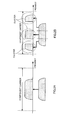
- Fig. 2A in the LTE system, contiguous frequency allocation to uplink transmission data is only allowed.
- Fig. 2B in the LTE-A system, discontiguous frequency allocation is allowed to uplink transmission data (Clustered DFT-S-OFDM).
- Discontiguous frequency allocation in the LTE-A system enables spot allocation in accordance with the reception environment by dividing and clustering the uplink transmission data into a plurality of frequency areas. This makes it possible to improve the spectrum efficiency of the system band and increase the frequency scheduling effect.
- the base station apparatus notifies the mobile terminal apparatus of RBG numbers indicating the starting RBG and the ending RBG of each cluster.
- the system band composed of 50 RBs is represented by the RBG #0 to the RBG #12, where 1 RBG is formed with 4 RBs. Therefore, the first cluster of the RB #8 to the RB #23 is set to range from the RBG #2 to the RBG #5, and the second cluster of the RB #36 to the RB #43 is set to range from the RBG #9 to the RBG #10. Accordingly, the base station apparatus notifies the mobile terminal apparatus of the starting RBG number "2" and the ending RBG number "5" of the first cluster and the starting RBG number "9" and the ending RBG number "10" of the second cluster. That is, the base station apparatus notifies the mobile terminal apparatus of four RBG numbers in total.
- the system band is not limited to 50 RBs but may be modified as appropriate.
- the number of signaling bits at this moment is calculated by the following formula (1) where the total number of RBGs (the total number of RBG numbers) is "N” and the number of RBG numbers "M” to be communicated to the mobile terminal apparatus is 4.
- Formula 1 X ⁇ log 2 N M ⁇
- the total number of RBGs (the total number of RBG numbers) is 13 and in comparison with the structure of signaling on a per-RB basis, the number of signaling bits can be reduced greatly.
- the starting RBG number is the same as the ending RBG number, and the first cluster cannot be indicated by signaling.
- the total number of RBG numbers is increased by 2 as compared with the total number of RBGs.
- the cluster set to the one RBG is defined by adjacent starting RBG number and ending RBG number.
- the first cluster when the first cluster is allocated to the n-th RBG #n singly, the first cluster is indicated by the starting RBG number n and the ending RBG number n+1.
- the first cluster When the first cluster is allocated to the n-th RBG #n to m-th RBG #m, the first cluster is indicated by the starting RBG number n and the ending RBG number m+1.
- the second cluster When the second cluster is allocated to the i-th RBG #i singly, the second cluster is indicated by the starting RBG number i+1 and the ending RBG number i+2.
- the second cluster when the second cluster is allocated to the i-th RBG #i to the j-th RBG #j, the second cluster is indicated by the starting RBG number i+1 and the ending RBG number j+2.
- the first cluster is allocated to the RBG #2
- the second cluster is allocated to the RBG #9 to the RBG #10
- the base station apparatus notifies the mobile terminal apparatus of the RBG numbers "2", “3", "10", and "12".
- the total number of RBG numbers at this moment is "15”
- cluster single allocation to one RBG is allowed while minimizing the number of signaling bits.
- the above-described signaling method covers the case, as illustrated in Fig. 4C , where the first cluster is adjacent to the second cluster.
- the structure in which the first cluster and the second cluster are adjacent to each other is not necessary, as illustrated in Fig. 4D , there may be considered another signaling method in which the total number of RBG numbers is reduced by one as compared with the above-described signaling method.
- the first cluster when the first cluster is allocated to the n-th RBG #n singly, the first cluster is indicated by the starting RBG number n and the ending RBG number n+1. And, when the first cluster is allocated to the n-th RBG #n to the m-th RBG #m, the first cluster is represented by the starting RBG number n and the ending RBG number m+1.
- the second cluster is allocated to the i-th RBG #i singly, the second cluster is represented by the starting RBG number i and the ending RBG number i+1. And, when the second cluster is allocated to the i-th RBG #i to the j-th RBG #j, the second cluster is represented by the starting RBG number i and the ending RBG number j+1.
- the first cluster is allocated to the RBG #2
- the second cluster is allocated to the RBG #4 to the RBG #5
- the base station apparatus notifies the mobile terminal apparatus of the RBG numbers "2", “3", "4" and "6".
- the total number of RBG numbers at this moment is "14"
- cluster single allocation to one RBG is allowed while further minimizing the number of signaling bits.
- the RBG size needs to be 4 RBs.
- the resource allocation width becomes rough and the sufficient frequency scheduling effect may not be obtained as compared with the case of reducing the RBG size to 2 RBs.
- the above-described method has a problem that the number of signaling bits is increased drastically as the total number of RBG numbers increases.
- the present inventors have carried out the present invention. That is, the gist of the present invention is to, noting that the number of signaling bits is increased by subdividing the RBG size, indicate a cluster of a relatively small RBG size with use of an RBG number of a relatively large RBG size.
- This structure enables detailed allocation of clusters to a predetermined frequency band, while preventing the increase in amount of signaling for resource allocation, thereby increasing the frequency scheduling effect.
- the signaling method is of signaling each cluster allocated to a frequency band of 2 RBs in RBG size with use of an RBG number of 4 RBs in RBG size.
- the signaling method is of signaling each cluster allocated to a frequency band of 2 RBs in RBG size with use of an RBG number of 4 RBs in RBG size.
- this is by no means limiting and may be modified as appropriate.
- Fig. 5 illustrates the system band where the RBG size is 4 RBs.
- the first-half 2 RBs and the latter-half 2 RBs of each RBG are configured to enable cluster single allocation. That is, this system band is divided into RBGs of a relatively small RBG size (2 RBs) and these RBGs of a relatively small size makes up RBGs of a relatively large RBG size (4 RBs).
- each cluster singly allocated to one RBG is indicated by adjacent starting RBG number and ending RBG number.
- the cluster singly allocated to the first-half 2 RBs of one RBG is indicated by a starting RBG number and an ending RBG number that is the second from the starting RBG number.
- the cluster singly allocated to the latter-half 2 RBs of one RBG is indicated by a starting RBG number and an ending RBG number that is the third from the starting RBG number.
- the instruction pattern of an allocation position by the RBG number is, for example, defined as follows.
- the first cluster is indicated by the starting RBG number n and the ending RBG number n+1.
- the first cluster is indicated by the starting RBG number n and the ending RBG number n+2.
- the first cluster is indicated by the starting RBG number n and the ending RBG number n+3.
- the first cluster is indicated by the starting RBG number n and the ending RBG number m+3.
- the second cluster when the second cluster is allocated to the i-th RBG #i singly, the second cluster is indicated by the starting RBG number i+2 and the ending RBG number i+3.
- the second cluster When the second cluster is allocated to the first-half 2 RBs of the i-th RBG #i singly, the second cluster is indicated by the starting RBG number i+2 and the ending RBG number i+4.
- the second cluster When the second cluster is allocated to the latter-half 2 RBs of the i-th RBG #i singly, the second cluster is indicated by the starting RBG number i+2 and the ending RBG number i+5.
- the second cluster when the second cluster is allocated to the i-th RBG #i to the j-th RBG #j, the second cluster is indicated by the starting RBG number i+2 and the ending RBG number j+5.
- the base station apparatus when the first cluster is allocated to the RBG #2 and the second cluster is allocated to the RBG #9 to the RBG #10, the base station apparatus notifies the mobile terminal apparatus of the RBG numbers "2", ⁇ °3", "11" and "15". And, as illustrated in Fig. 5B , when the first cluster is allocated to the first-half 2 RBs of the RBG #2 and the second cluster is allocated to the RBG #9 to the RBG #10, the base station apparatus notifies the mobile terminal apparatus of the RBG numbers "2", "4", "11” and “15”. Further, as illustrated in Fig.
- the base station apparatus when the first cluster is allocated to the latter-half 2 RBs of the RBG #2 and the second cluster is allocated to the RBG #9 to the RBG #10, the base station apparatus notifies the mobile terminal apparatus of the RBG numbers "2", "5", "11" and "15".
- signaling can be performed of a cluster allocated to a half size of one RBG while minimizing the increase in number of signaling bits.
- a cluster of a relatively small RBG size is signaled with use of an RBG number of a relatively large RBG size.
- the instruction pattern of the allocation position by the RBG number may be defined in advance between the base station apparatus 20 and the mobile terminal apparatus 10 or synchronized at predetermined timings.
- the cluster set to one RBG is indicated by adjacent starting RBG number and ending RBG number.
- this structure is by no means limiting.
- the cluster set to one RBG may be indicated by a starting RBG number and an ending RBG number that is the second from the starting RBG number, or indicated by a starting RBG number and an ending RBG number that is the third from the starting RBG number.
- the cluster set to first-half 2 RBs of one RBG is indicated by a starting RBG number and an ending RBG number that is the second from the starting RBG number.
- this structure is by no means limiting.
- the cluster set to the first-half 2 RBs of one RBG may be indicated by a starting RBG number and an ending RBG number that are adjacent to each other or indicated by a starting RBG number and an ending RBG number that is the third from the starting RBG number, or the like.
- the cluster set to latter-half 2 RBs of one RBG is indicated by a starting RBG number and an ending RBG number that is the third from the starting RBG number.
- this structure is by no means limiting.
- the cluster set to the latter-half 2 RBs of one RBG may be indicated by a starting RBG number and an ending RBG number that are adjacent to each other or indicated by a starting RBG number and an ending RBG number that is the second from the starting RBG number, or the like.
- each cluster allocated to a frequency band of 2 RBs in RBG size can be signaled by using an RBG number composed of 4 RBs in RBG size.
- this structure is by no means limiting.
- the allocation position of each cluster allocated to a frequency band of RBGs of a relatively small RBG size or to a frequency band of RBs may be signaled by using an RBG number of a relatively large RBG size.
- the present invention may be configured to signal the allocation position of each cluster allocated to one RB by using an RBG number of 2 RBs in RBG size, or to signal the allocation position of each cluster allocated to one RB by using an RBG number of 3 RBs in RBG size.
- a radio communication system 1 having mobile terminal apparatuses (UE: User Equipment) 10 and a base station apparatus (Node B) 20 according to an embodiment of the present invention.
- UE User Equipment
- Node B base station apparatus
- Fig. 6 is a diagram for explaining a configuration of the mobile communication system 1 having the base station apparatus 20 and the mobile terminal apparatuses 10 according to the present embodiment.
- the radio communication system 1 illustrated in Fig. 6 is a system subsuming, for example, the LTE system or SUPER 3G. Also, this radio communication system 1 may be referred to as IMT-Advanced or may be referred to as 4G.
- the radio communication system 1 is configured to include the base station apparatus 20 and a plurality of mobile terminal apparatuses 10 (10 1 , 10 2 , 10 3 , ... 10 n , where n is an integer to satisfy n>0) that communicate with the base station apparatus 20.
- the base station apparatus 20 is connected with a higher station apparatus 30, and this higher station apparatus 30 is connected with a core network 40.
- the mobile terminal apparatuses 10 communicate with the base station apparatus 20 in a cell 50.
- the higher station apparatus 30 includes, for example, an access gateway apparatus, a radio network controller (RNC), a mobility management entity (MME) and so on, but is by no means limited to these.
- RNC radio network controller
- MME mobility management entity
- the mobile terminal apparatuses (10 1 , 10 2 , 10 3 , ... 10 n ) include LTE terminals and LTE-A terminals, however, in the following description, they are referred to as "mobile terminal apparatuses 10," unless specified otherwise. Also, for ease of explanation, the mobile terminal apparatus 10 performs radio communication with the base station apparatus 20. However, more generally, user apparatuses (UE: User Equipment) including mobile terminal apparatuses and fixed terminal apparatuses may be used.
- UE User Equipment
- OFDMA Orthogonal Frequency Division Multiple Access
- SC-FDMA Single-Carrier Frequency-Division Multiple Access
- SC-FDMA Single-Carrier Frequency-Division Multiple Access
- SC-FDMA Single-Carrier Frequency-Division Multiple Access
- SC-FDMA Single-Carrier Frequency-Division Multiple Access
- SC-FDMA is a single carrier transmission scheme to reduce interference between terminals by dividing, per terminal, the system band into bands formed with one or continuous resource blocks, and allowing a plurality of terminals to use mutually different bands.
- Clustered DFT-Spread OFDM is a scheme to realize uplink multiple access by allocating a group (cluster) of discontiguous clustered subcarriers to one mobile station (UE) and applying discrete Fourier transform spread OFDM to the each cluster.
- the downlink communication channels include the PDSCH (Physical downlink Shared CHannel), which is a downlink data channel used by each mobile terminal apparatus 10 on a shared basis, and downlink L1/L2 control channels (PDCCH, PCFICH and PHICH).
- the PDSCH transmits user data and higher control information.
- Scheduling information for the PDSCH and PUSCH (Physical Uplink Shared CHannel) and so on is transmitted by the PDCCH (Physical Downlink Control CHannel).
- the number of OFDM symbols to use for the PDCCH is transmitted by the PCFICH (Physical Control Format Indicator CHannel).
- HARQ ACK/NACK for the PUSCH is transmitted by the PHICH (Physical Hybrid-ARQ Indicator CHannel).
- the higher control signals include RRC signaling, which reports uplink radio access schemes (SC-FDMA/Clustered DFT-Spread OFDM) applied to each component carrier to the mobile terminal apparatus 10.
- the uplink communication channels include a PUSCH, which is an uplink data channel used by each mobile terminal apparatus 10 on a shared basis, and a PUCCH (Physical Uplink Control CHannel), which is an uplink control channel. User data and higher control information are transmitted by means of this PUSCH. Furthermore, the PUCCH transmits downlink radio quality information (CQI: Channel Quality Indicator), ACK/NACK, and so on.
- CQI Channel Quality Indicator
- the base station apparatus 20 has a transmitting/receiving antenna 201, an amplifying section 202, a transmitting/receiving section 203, a baseband signal processing section 204, a call processing section 205 and a transmission path interface 206.
- User data that is transmitted on the downlink from the base station apparatus 20 to the mobile terminal apparatus 10 is input to the baseband signal processing section 204, through the transmission path interface 206, from the higher station apparatus 30.
- a downlink data channel signal is subjected to PDCP layer processing, RLC (Radio Link Control) layer transmission processing such as division and coupling of user data and RLC retransmission control transmission processing, MAC (Medium Access Control) retransmission control, including, for example, HARQ (Hybrid Automatic Repeat reQuest) transmission processing, scheduling, transport format selection, channel coding, inverse fast Fourier transform (IFFT) processing, and precoding processing.
- HARQ Hybrid Automatic Repeat reQuest
- the baseband signal processing section 204 passes control information for allowing the mobile terminal apparatus 10 to perform radio communication with the base station apparatus 20, to the mobile terminal apparatuses 10 connected to the same cell 50, by a broadcast channel.
- Broadcast information for communication in the cell 50 includes, for example, the uplink or downlink system bandwidth, identification information of a root sequence (root sequence index) for generating random access preamble signals in the PRACH (Physical Random Access CHannel), and so on.
- the baseband signal output from the baseband signal processing section 204 is subjected to frequency conversion processing into a radio frequency band.
- the amplifying section 202 amplifies the transmission signal having been subjected to frequency conversion, and outputs the result to the transmitting/receiving antenna 201.
- a radio frequency signal that is received in the transmitting/receiving antenna 201 is amplified in the amplifying section 202, subjected to frequency conversion and converted into a baseband signal in the transmitting/receiving section 203, and is input to the baseband signal processing section 204.
- the baseband signal processing section 204 performs FFT processing, IDFT processing, error correction decoding, MAC retransmission control reception processing, and RLC layer and PDCP layer reception processing of the user data included in the baseband signal that is received on the uplink.
- the decoded signal is transferred to the higher station apparatus 30 through the transmission path interface 206.
- the call processing section 205 performs call processing such as setting up and releasing a communication channel, manages the state of the base station apparatus 20 and manages the radio resources.
- the mobile terminal apparatus 10 has a transmitting/receiving antenna 101, an amplifying section 10 2 , a transmitting/receiving section 10 3 , a baseband signal processing section 104 and an application section 105.
- a radio frequency signal received in the transmitting/receiving antenna 101 is amplified in the amplifying section 10 2 , and subjected to frequency conversion and converted into a baseband signal in the transmitting/receiving section 103.
- This baseband signal is subjected to reception processing such as FFT processing, error correction decoding and retransmission control and so on, in the baseband signal processing section 104.
- downlink user data is transferred to the application section 105.
- the application section 105 performs processing related to higher layers above the physical layer and the MAC layer. Also, in the downlink data, broadcast information is also transferred to the application section 105.
- uplink user data is input from the application section 105 to the baseband signal processing section 104.
- the baseband signal processing section 104 retransmission control (HARQ (Hybrid ARQ)) transmission processing, channel coding, DFT processing, IFFT processing and so on are performed.
- HARQ Hybrid ARQ
- the baseband signal output from the baseband signal processing section 104 is subjected to frequency conversion processing in the transmitting/receiving section 103 and converted into a radio frequency band, and, after that, amplified in the amplifying section 102 and transmitted from the transmitting/receiving antenna 101.
- Fig. 9 is a functional block diagram of the baseband signal processing section 204 and part of the higher layers provided in the base station apparatus 20 according to the present embodiment, and primarily illustrates the functional blocks of the transmission processing section in the baseband signal processing section 204.
- Fig. 9 illustrates an example of a base station configuration which can support maximum M (CC #1 to CC #M) component carriers. Transmission data for the mobile terminal apparatus 10 under control of the base station apparatus 20 is transferred from the higher station apparatus 30 to the base station apparatus 20.
- M maximum M
- a control information generating section 300 generates higher control information for performing higher layer signaling (for example, RRC signaling), on a per-user basis.
- the higher control information may contain an instruction pattern of allocation position by an RBG number.
- the higher control information may contain an uplink radio access scheme to be passed to the mobile terminal apparatus 10.
- a data generating section 301 outputs the transmission data transferred from the higher station apparatus 30 separately as user data.
- a component carrier selecting section 302 selects component carriers to use in radio communication with the mobile terminal apparatus 10 on a per-user basis.
- a scheduling section 310 controls allocation of component carriers to a serving mobile terminal apparatus 10 according to overall communication quality of the system band.
- SC-FDMA or clustered DFT-Spread OFDM is controlled dynamically (per subframe).
- the number of clusters and cluster resources are determined.
- the scheduling section 310 controls resource allocation in component carriers CC #1 to CC #M.
- the LTE terminal user and the LTE-A terminal user are scheduled separately.
- the scheduling section 310 receives as input the transmission data and retransmission command from the higher station apparatus 30, and also receives as input the channel estimation values and resource block CQIs from the receiving section having measured an uplink received signal.
- the scheduling section 310 schedules uplink and downlink control information and uplink and downlink shared channel signals, with reference to the retransmission command, channel estimation values and CQIs that are received as input from the higher station apparatus 30.
- a propagation path in mobile communication varies differently per frequency, due to frequency selective fading.
- adaptive frequency scheduling For each resource block, a mobile terminal apparatus 10 of good propagation path quality is selected and assigned. Consequently, the scheduling section 310 assigns resource blocks, using the CQI of each resource block, fed back from each mobile terminal apparatus 10. Also, the MCS (coding rate and modulation scheme) to fulfill a required block error rate with the assigned resource blocks is determined. Parameters to fulfill the MCS (coding rate and modulation scheme) determined by the scheduling section 310 are set in channel coding sections 303, 308 and 312, and in modulating sections 304, 309 and 313.
- resources of each cluster are determined on a per-RBG basis where the RBG is a group of contiguous resource blocks.
- the RBG size is 4 RBs
- plural allocation and single allocation are supported and when the RBG size is 2 RBs, single allocation is only supported.
- the RBG size is 4 RBs
- single allocation to the RBG #2 by the first cluster and plural allocation to the RBG #9 to the RBG #10 by the second cluster are allowed.
- the baseband signal processing section 204 has channel coding sections 303, modulating sections 304, and mapping sections 305, to match the maximum number of users to be multiplexed, N, in one component carrier.
- the channel coding section 303 performs channel coding of the shared data channel (PDSCH), which is formed with user data (including part of higher control signals) that is output from the data generating section 301, on a per-user basis.
- the modulating section 304 modulates user data having been subjected to channel coding, on a per-user basis.
- the mapping section 305 maps the modulated user data to radio resources.
- the baseband signal processing section 204 has a downlink control information generating section 306 that generates downlink shared data channel control information, which is user-specific downlink control information, and a downlink shared channel control information generating section 307 that generates downlink shared control channel control information, which is user-common downlink control information.
- the downlink control information generating section 306 generates downlink control signals (DCI) of PDCCH from the resource allocation information, PUCCH transmission power control command, which are determined on a per-user basis. Also, the downlink control information generating section 306 generates HARQ ACK/NACK for a reception signal on which uplink layers are spatially multiplexed.
- DCI downlink control signals
- the baseband signal processing section 204 has channel coding sections 308 and modulating sections 309 to match the maximum number of users to be multiplexed, N, in one component carrier.
- the channel coding section 308 performs, on a per-user basis, channel coding of control information, which is generated in the downlink control information generating section 306 and the downlink shared channel control information generating section 307.
- the modulating section 309 modulates the downlink control information having been subjected to channel coding.
- the baseband signal processing section 204 has an uplink control information generating section 311, a channel coding section 312, and a modulating section 313.
- the uplink control information generating section 311 generates, on a per-user basis, uplink shared data channel control information (UL grant and so on), which is control information for controlling the uplink shared data channel (PUSCH).
- the channel coding section 312 performs, on a per-user basis, channel coding of uplink shared data channel control information
- the modulating section 313 modulates the uplink shared data channel control information having been subjected to channel coding, on a per-user basis.
- the uplink control information generating section 311 generate uplink allocation information from uplink resource allocation information (cluster) that is determined per user, MCS information and redundancy version (RV), an identifier (new data indicator) to identify new data or retransmission data, a transmission power control command (TPC) of PUSCH, cyclic shift for the demodulation reference signal (CS for DMRS), CQI request, and so on.
- uplink resource allocation information cluster
- RV redundancy version
- TPC transmission power control command
- CS for DMRS cyclic shift for the demodulation reference signal
- CQI request CQI request, and so on.
- the resource allocation information is generated with a starting RBG number and an ending RBG number of each cluster, the total number of RBG numbers and so on.
- the starting RBG number and the ending RBG number indicate the allocation position of each cluster in accordance with the above-described signaling method of the present invention.
- the cluster set to one RBG is indicated by a starting RBG number and an ending RBG number which are adjacent to each other.
- the cluster set to the first-half 2 RBs of one RBG is indicated by a starting RBG number and an ending RBG number that is the second from the starting RBG number.
- the cluster set to the latter-half 2 RBs of one RBG is indicated by a starting RBG number and an ending RBG number that is the third from the starting RBG number.
- the control information that is modulated on a per-user basis in the above modulating sections 309 and 313 is multiplexed in a control channel multiplexing section 314 and furthermore interleaved in an interleaving section 315.
- a control signal that is output from the interleaving section 315 and user data that is output from the mapping section 305 are input into an IFFT section 316 as a downlink channel signal.
- the IFFT section 316 converts the downlink channel signal from a frequency domain signal into a time sequence signal by performing an inverse fast Fourier transform of the downlink channel signal.
- a cyclic prefix inserting section 317 inserts cyclic prefixes in the time sequence signal of the downlink channel signal. Note that a cyclic prefix functions as a guard interval for cancelling the differences in multipath propagation delay.
- the transmission data to which cyclic prefixes are added, is transmitted to the transmitting/receiving section 203.
- Fig. 10 is a functional block diagram of the baseband signal processing section 104 provided in the mobile terminal apparatus 10, illustrating functional blocks of an LTE-A terminal supporting LTE-A. First description is made about a downlink configuration of the mobile terminal apparatus 10.
- a CP removing section 401 removes the CPs from a downlink signal received from the radio base station apparatus 20 as received data.
- the downlink signal, from which the CPs have been removed, is input into an FFT section 402.
- the FFT section 402 performs a fast Fourier transform (FFT) on the downlink signal, converts the time-domain signal into a frequency domain signal, and inputs the frequency domain signal into a demapping section 403.
- the demapping section 403 demaps the downlink signal, and extracts, from the downlink signal, multiplexed control information in which a plurality of pieces of control information are multiplexed, user data, and higher control signals.
- the demapping process by the demapping section 403 is performed based on higher control information that is received as input from the application section 105.
- the multiplexed control information that is output from the demapping section 403 is deinterleaved in a deinterleaving section 404.
- the baseband signal processing section 104 has a control information demodulating section 405 that demodulates control information, a data demodulating section 406 that demodulates downlink shared data, and a channel estimating section 407.
- the control information demodulating section 405 includes a shared control channel control information demodulating section 405a that demodulates downlink shared control channel control information from the multiplexed control information, an uplink shared data channel control information demodulating section 405b that demodulates uplink shared data channel control information from the multiplexed control information, and a downlink shared data channel control information demodulating section 405c that demodulates downlink shared data channel control information from the multiplexed control information.
- the data demodulating section 406 includes a downlink shared data demodulating section 406a that demodulates the user data and higher control signals, and a downlink shared channel data demodulating section 406b that demodulates downlink shared channel data.
- the shared control channel control information demodulating section 405a extracts shared control channel control information, which is user-common control information, by the blind decoding processing of the common search spaces of the multiplexed control information (PDCCH), demodulation processing, channel decoding processing and so on.
- the shared control channel control information includes downlink channel quality information (CQI), and therefore is input into a mapping section 415 (described later), and mapped as part of transmission data for the base station apparatus 20.
- the uplink shared data channel control information demodulating section 405b extracts uplink shared data channel control information, which is user-specific uplink allocation information, by the blind decoding processing of the user-specific search spaces of the multiplexed control information (PDCCH), demodulation processing, channel decoding processing and so on.
- the uplink allocation information is used to control the uplink shared data channel (PUSCH), and is input to the downlink shared data channel control information demodulating section 405c and the downlink shared channel data demodulating section 406b.
- the resource allocation information (RBG number) to indicate the cluster allocation position is extracted.
- the downlink shared data channel control information demodulating section 405c extracts downlink shared data channel control information, which is user-specific downlink control signals, by the blind decoding processing of the user-specific search spaces of the multiplexed control information (PDCCH), demodulation processing, channel decoding processing and so on.
- the downlink shared data channel control information is used to control the downlink shared data channel (PDSCH), and is input to the downlink shared data demodulating section 406.
- the downlink shared data channel control information demodulating section 405c performs the blind decoding process of the user-specific search spaces, based on information which relates to the PDCCH and PDSCH and which is included in higher control information demodulated in the downlink shared data demodulating section 406a.
- the downlink shared data demodulating section 406a acquires the user data and higher control information based on the downlink shared data channel control information received as input from the downlink shared data channel control information demodulating section 405c.
- the higher control information is output to the channel estimating section 407.
- the downlink shared channel data demodulating section 406b demodulates downlink shared channel data based on the uplink shared data channel control information that is input from the uplink shared data channel control information demodulating section 405b.
- the channel estimating section 407 performs channel estimation using common reference signals.
- the estimated channel variance is output to the shared control channel control information demodulating section 405a, the uplink shared data channel control information demodulating section 405b, the downlink shared data channel control information demodulating section 405c and the downlink shared data demodulating section 406a.
- These demodulating sections demodulate downlink signals using the estimated channel variance and demodulation reference signals.
- the baseband signal processing section 104 has a data generating section 411, a channel coding section 412, a modulating section 413, a DFT section 414, a mapping section 415, an IFFT section 416, and a CP inserting section 417, which are provided as functional blocks of transmission processing sequence.
- the data generating section 411 generates transmission data from bit data that is received as input from the application section 105.
- the channel coding section 412 applies channel coding processing such as error correction and so on to the transmission data, and the modulating section 413 modulates the transmission data having been subjected to channel coding by QPSK and so on.
- the DFT section 414 performs discrete Fourier transform on the modulated transmission data.
- the mapping section 415 maps frequency components of data symbols having been subjected to DFT, to subcarrier positions indicated by the base station apparatus 20.
- the mapping section 415 is notified of the resource allocation information of each demodulated cluster by the uplink shared data channel control information demodulating section 405b.
- the mapping section 415 maps the frequency components of the data symbols to discontiguous allocation positions (subcarrier positions) indicated by the RBG numbers of the resource allocation information.
- SC-FDMA is applied to the uplink
- the mapping section 415 maps the frequency components of the data symbols to contiguous allocation positions (subcarrier positions) indicated by the resource allocation position.
- the IFFT section 416 performs inverse fast Fourier transform on input data corresponding to the system band and converts it to time sequence data and the CP inserting section 417 insert cyclic prefixes to the time sequence data at intervals between data pieces.
- the allocation position of a cluster allocated per RBG of a relatively small size can be indicated to the mobile terminal apparatus 10 by an RBG number of a relatively large RBG size. Accordingly, it becomes possible to prevent the increase in amount of signaling for uplink resource allocation which is caused by subdividing the allocation size of each cluster in the frequency band. Hence, it is possible to perform detailed allocation of a plurality of clusters to the frequency band while preventing the increase in signaling amount, thereby increasing the frequency scheduling effect.
- the number of clusters is 2. However, this is by no means limiting.
- the number of clusters may be 3 or more. If the number of clusters is 3 or more, it is possible to indicate each cluster allocated in a relatively small RBG size with use of an RBG number of a relatively large RBG size, like in the case where the number of clusters is 2.
- single allocation of the first cluster and the second cluster to half RBs of one RBG is allowed.
- Single allocation to half RBs of one RBG may be allowed only to any of the plural clusters.
- the first cluster is allowed to be allocated singly to half RBs of one RBG, it is possible to reduce the total number of RBG numbers and further reduce the number of signaling bits for uplink resource allocation.
- the present invention is not limited to the above-mentioned embodiments and may be embodied in various modified formed.
- the allocation of clusters, the number of processing sections, the processing procedures, the number of clusters and RBG size may be modified as appropriate without departing from the scope of the present invention. Any other modifications may be also made to the present invention without departing from the scope of the present invention.
Landscapes
- Engineering & Computer Science (AREA)
- Signal Processing (AREA)
- Computer Networks & Wireless Communication (AREA)
- Mobile Radio Communication Systems (AREA)
Applications Claiming Priority (2)
| Application Number | Priority Date | Filing Date | Title |
|---|---|---|---|
| JP2010181907A JP5298086B2 (ja) | 2010-08-16 | 2010-08-16 | 基地局装置、移動端末装置および通信制御方法 |
| PCT/JP2011/067886 WO2012023443A1 (ja) | 2010-08-16 | 2011-08-04 | 基地局装置、移動端末装置および通信制御方法 |
Publications (1)
| Publication Number | Publication Date |
|---|---|
| EP2608597A1 true EP2608597A1 (en) | 2013-06-26 |
Family
ID=45605099
Family Applications (1)
| Application Number | Title | Priority Date | Filing Date |
|---|---|---|---|
| EP11818085.0A Withdrawn EP2608597A1 (en) | 2010-08-16 | 2011-08-04 | Base station apparatus, mobile terminal apparatus and communication control method |
Country Status (4)
| Country | Link |
|---|---|
| US (1) | US20130182673A1 (ja) |
| EP (1) | EP2608597A1 (ja) |
| JP (1) | JP5298086B2 (ja) |
| WO (1) | WO2012023443A1 (ja) |
Cited By (2)
| Publication number | Priority date | Publication date | Assignee | Title |
|---|---|---|---|---|
| WO2019174584A1 (zh) * | 2018-03-12 | 2019-09-19 | 华为技术有限公司 | 一种数据传输方法、相关设备及系统 |
| RU2713599C2 (ru) * | 2015-10-29 | 2020-02-05 | Панасоник Интеллекчуал Проперти Менеджмент Ко., Лтд. | Устройство связи, терминал и способ связи |
Families Citing this family (6)
| Publication number | Priority date | Publication date | Assignee | Title |
|---|---|---|---|---|
| WO2014098689A1 (en) | 2012-12-21 | 2014-06-26 | Telefonaktiebolaget L M Ericsson (Publ) | Network node and method for allocating uplink radio resources |
| JP5651767B2 (ja) * | 2013-12-10 | 2015-01-14 | 京セラドキュメントソリューションズ株式会社 | 印刷データ処理装置及びプログラム並びに画像形成装置 |
| US10004081B2 (en) | 2015-12-15 | 2018-06-19 | Marvell World Trade Ltd. | Systems and methods for providing resource signaling within a wireless local area network (WLAN) |
| US10790957B2 (en) * | 2016-06-22 | 2020-09-29 | Lg Electronics Inc. | Method and apparatus for allocating resources to FDR-mode UE in a wireless communication system |
| CN109891986B (zh) | 2016-11-02 | 2022-07-29 | 株式会社Ntt都科摩 | 用户装置及上行信号发送方法 |
| CN109150269B (zh) * | 2017-06-16 | 2021-11-26 | 华为技术有限公司 | 一种信令接收方法、指示方法、终端、网络设备和存储介质 |
Family Cites Families (2)
| Publication number | Priority date | Publication date | Assignee | Title |
|---|---|---|---|---|
| EP2262337B1 (en) * | 2009-06-10 | 2017-03-15 | Innovative Sonic Corporation | Method and apparatus for allocating uplink resource |
| JP4653246B2 (ja) | 2010-04-16 | 2011-03-16 | 日立プラズマディスプレイ株式会社 | プラズマディスプレイ装置及びその表示方法 |
-
2010
- 2010-08-16 JP JP2010181907A patent/JP5298086B2/ja not_active Expired - Fee Related
-
2011
- 2011-08-04 WO PCT/JP2011/067886 patent/WO2012023443A1/ja active Application Filing
- 2011-08-04 EP EP11818085.0A patent/EP2608597A1/en not_active Withdrawn
- 2011-08-04 US US13/817,109 patent/US20130182673A1/en not_active Abandoned
Non-Patent Citations (1)
| Title |
|---|
| See references of WO2012023443A1 * |
Cited By (4)
| Publication number | Priority date | Publication date | Assignee | Title |
|---|---|---|---|---|
| RU2713599C2 (ru) * | 2015-10-29 | 2020-02-05 | Панасоник Интеллекчуал Проперти Менеджмент Ко., Лтд. | Устройство связи, терминал и способ связи |
| US11564261B2 (en) | 2015-10-29 | 2023-01-24 | Panasonic intellectual property Management co., Ltd | Communication apparatus, terminal station, and communication method for random access resource allocation |
| WO2019174584A1 (zh) * | 2018-03-12 | 2019-09-19 | 华为技术有限公司 | 一种数据传输方法、相关设备及系统 |
| US11317425B2 (en) | 2018-03-12 | 2022-04-26 | Huawei Technologies Co., Ltd. | Data transmission method, related device, and system |
Also Published As
| Publication number | Publication date |
|---|---|
| JP2012044331A (ja) | 2012-03-01 |
| US20130182673A1 (en) | 2013-07-18 |
| JP5298086B2 (ja) | 2013-09-25 |
| WO2012023443A1 (ja) | 2012-02-23 |
Similar Documents
| Publication | Publication Date | Title |
|---|---|---|
| US9723603B2 (en) | Radio base station apparatus, user terminal and radio communication method | |
| US8982752B2 (en) | Base station apparatus and user terminal | |
| US9185724B2 (en) | Aperiodic channel state information reporting method, radio base station apparatus and user terminal | |
| US9137803B2 (en) | Radio communication control method, base station apparatus and mobile terminal apparatus | |
| US9801159B2 (en) | Base station apparatus, mobile terminal apparatus and communication control method | |
| EP2557879A1 (en) | Wireless communication control device and wireless communication control method | |
| US9439181B2 (en) | Radio communication system, radio base station apparatus, user terminal, and radio communication method | |
| JP5979968B2 (ja) | ユーザ端末、無線通信方法及び無線通信システム | |
| US9439182B2 (en) | Radio communication system, radio base station apparatus, user terminal and radio communication method | |
| US9313014B2 (en) | Radio communication system, radio communication method, radio base station apparatus and user terminal | |
| US20120289286A1 (en) | Base station apparatus and system information notification method | |
| EP2608597A1 (en) | Base station apparatus, mobile terminal apparatus and communication control method | |
| EP2747502A1 (en) | Communication system, base station device, mobile terminal device and communication method | |
| EP2566270A1 (en) | Base station device and user terminal | |
| WO2011125996A1 (ja) | 基地局装置、移動端末装置および通信制御方法 | |
| JP5280573B2 (ja) | 無線通信システム、通信制御方法、基地局装置及び移動端末装置 |
Legal Events
| Date | Code | Title | Description |
|---|---|---|---|
| PUAI | Public reference made under article 153(3) epc to a published international application that has entered the european phase |
Free format text: ORIGINAL CODE: 0009012 |
|
| 17P | Request for examination filed |
Effective date: 20130222 |
|
| AK | Designated contracting states |
Kind code of ref document: A1 Designated state(s): AL AT BE BG CH CY CZ DE DK EE ES FI FR GB GR HR HU IE IS IT LI LT LU LV MC MK MT NL NO PL PT RO RS SE SI SK SM TR |
|
| DAX | Request for extension of the european patent (deleted) | ||
| STAA | Information on the status of an ep patent application or granted ep patent |
Free format text: STATUS: THE APPLICATION HAS BEEN WITHDRAWN |
|
| 18W | Application withdrawn |
Effective date: 20150316 |