EP2608363A1 - Flansche für die Unterstützung der Wickelköpfe und Schenkelpol- Rotor mit den Flanschen - Google Patents
Flansche für die Unterstützung der Wickelköpfe und Schenkelpol- Rotor mit den Flanschen Download PDFInfo
- Publication number
- EP2608363A1 EP2608363A1 EP12192330.4A EP12192330A EP2608363A1 EP 2608363 A1 EP2608363 A1 EP 2608363A1 EP 12192330 A EP12192330 A EP 12192330A EP 2608363 A1 EP2608363 A1 EP 2608363A1
- Authority
- EP
- European Patent Office
- Prior art keywords
- rotor
- flange
- flanges
- orifices
- sheets
- Prior art date
- Legal status (The legal status is an assumption and is not a legal conclusion. Google has not performed a legal analysis and makes no representation as to the accuracy of the status listed.)
- Granted
Links
Images


Classifications
-
- H—ELECTRICITY
- H02—GENERATION; CONVERSION OR DISTRIBUTION OF ELECTRIC POWER
- H02K—DYNAMO-ELECTRIC MACHINES
- H02K3/00—Details of windings
- H02K3/46—Fastening of windings on the stator or rotor structure
- H02K3/50—Fastening of winding heads, equalising connectors, or connections thereto
- H02K3/51—Fastening of winding heads, equalising connectors, or connections thereto applicable to rotors only
-
- H—ELECTRICITY
- H02—GENERATION; CONVERSION OR DISTRIBUTION OF ELECTRIC POWER
- H02K—DYNAMO-ELECTRIC MACHINES
- H02K1/00—Details of the magnetic circuit
- H02K1/06—Details of the magnetic circuit characterised by the shape, form or construction
- H02K1/22—Rotating parts of the magnetic circuit
- H02K1/24—Rotor cores with salient poles ; Variable reluctance rotors
-
- H—ELECTRICITY
- H02—GENERATION; CONVERSION OR DISTRIBUTION OF ELECTRIC POWER
- H02K—DYNAMO-ELECTRIC MACHINES
- H02K1/00—Details of the magnetic circuit
- H02K1/06—Details of the magnetic circuit characterised by the shape, form or construction
- H02K1/22—Rotating parts of the magnetic circuit
- H02K1/32—Rotating parts of the magnetic circuit with channels or ducts for flow of cooling medium
- H02K1/325—Rotating parts of the magnetic circuit with channels or ducts for flow of cooling medium between salient poles
-
- H—ELECTRICITY
- H02—GENERATION; CONVERSION OR DISTRIBUTION OF ELECTRIC POWER
- H02K—DYNAMO-ELECTRIC MACHINES
- H02K9/00—Arrangements for cooling or ventilating
- H02K9/02—Arrangements for cooling or ventilating by ambient air flowing through the machine
- H02K9/04—Arrangements for cooling or ventilating by ambient air flowing through the machine having means for generating a flow of cooling medium
- H02K9/06—Arrangements for cooling or ventilating by ambient air flowing through the machine having means for generating a flow of cooling medium with fans or impellers driven by the machine shaft
Definitions
- the invention relates to a rotor with salient poles comprising flanges for holding winding coils and associated holding flanges.
- the invention finds a particularly advantageous application in the field of rotating electrical machines such as alternators, alternator-starters and electromagnetic retarders.
- the document WO 2007/003835 has a protruding poles rotor for a rotating electrical machine including an alternator or a starter-alternator for a motor vehicle.
- an alternator / starter is a rotating electrical machine able to work in a reversible manner, on the one hand, as an electric generator in alternator function and, on the other hand, as an electric motor in particular for starting the engine of the motor vehicle .
- This machine essentially comprises a housing and, inside thereof, a rotor fixed in rotation with a central rotor shaft and an annular stator which surrounds the rotor coaxially with the shaft.
- the stator comprises a body in the form of a pack of sheets with notches, for example of the semi-closed type, for mounting a stator winding having a plurality of windings.
- This stator winding comprises for example a set of three-phase star or delta windings, the outputs of which are connected to a rectifier bridge comprising rectifying elements.
- the alternator is of the polyphase type and the rectifier bridge or bridges make it possible in particular to rectify the alternating current produced in the stator windings in a direct current, in particular for charging the battery of the motor vehicle and supplying the loads and electrical consumers of the on-board network of the motor vehicle.
- the housing has an intermediate portion internally bearing the body of the stator. This intermediate portion is interposed axially between the bearings each having a plurality of openings for internal ventilation of the machine with at least one fan secured to one of the axial ends of the rotor.
- This fan has blades integral with a flange as described below.
- the rotor shaft carries at its front end a pulley which is arranged outside the housing.
- the pulley belongs to a motion transmission device via at least one belt between the alternator and the engine of the motor vehicle.
- the sheets of the sheet package all have an identical contour.
- the outline of the sheets is cut into a generally circular shape and having salient poles, which are regularly distributed in a radial direction and projecting from the shaft towards the outer periphery.
- the sheet package has at least two poles.
- Each pole consists of an arm which, from the core, extends radially towards the outer periphery towards the stator.
- the free end of the pole ends with a return protruding circumferentially on either side of the arm.
- An annular gap exists between the free end of the poles and the inner periphery of the stator body.
- the slip rings are electrically powered by means of brushes which belong to a brush holder and which are arranged so as to rub on the slip rings.
- the brush holder is generally arranged in the housing and is electrically connected to a voltage regulator.
- a first front flange and a second rear flange are mounted coaxially to the shaft so as to axially clamp the sheet of paper to keep the stacked sheets in a package.
- Each flange has globally the shape of a disk extending in a radial plane perpendicular to the axis of the shaft.
- Each flange has a central hole for coaxial mounting on the shaft.
- the bun is in contact with the bottom of the housing via a heat conductive and non-conductive substance.
- electricity which protects the wires of the excitation winding.
- the substance is here a coating of impregnation conductive heat and electrical insulation. This varnish cures by polymerization.
- One of the flanges has filling holes which each open into the bottom of an associated housing. These filling holes are intended to allow the impregnation of the liquid varnish around the excitation winding associated with said housing, and more particularly around the two bunches of the excitation winding.
- each flange comprises blades forming a fan.
- Each blade extends axially outwardly from the outer radial face of the associated flange.
- the object of the invention is in particular to propose an improved projecting pole rotor enabling improved cooling without necessarily having to carry out a varnish impregnation step.
- each flange has a second series of orifices orifices implanted outside the first series of orifices.
- the first series of orifices of one of the flanges is wider circumferentially and higher radially than the first series of orifices of the other flange.
- each flange has counterbores radially affecting the outer periphery of the radial wall and axially partly the flange.
- At least one of the flanges carries ventilation blades positioned on a first face of the radial wall facing outwardly of the rotor.
- the fan blades belong to a separate fan attached to fixing on the flange for example by spot welding, screwing or riveting.
- the fan blades belong to the flange being in one piece with this flange.
- each orifice of the second series is positioned between two successive blades.
- the rotor further comprises two insulating elements positioned on either side of the sheet metal package, ensuring the insulation of buns.
- one of the insulating elements has guide pins connecting wires between the coils.
- the insulating elements comprise at least two latching devices intended to cooperate by snapping with openings provided on each radial end face of the sheet package.
- each flange comprises at least one centering pin intended to cooperate with axial openings formed in the salient poles.
- each flange comprises at least two orifices, the holes of the flanges and the axial openings of the poles ensuring the passage of tie rods to assemble the flanges around the sheet package.
- the free end of a pole terminates in a circumferentially protruding return on either side of an arm and the rotor comprises at least one magnet positioned between two returns of two adjacent salient poles.
- the flanges are made of non-magnetic material, such as aluminum or plastic material advantageously reinforced by fibers.
- Figure 1 an axial sectional view of a rotary electric machine provided with a rotor according to the invention
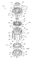
- Figure 2 an exploded perspective view of a rotor according to the invention which is not wound;
- Figures 3a and 3b perspective views of a wound rotor according to the invention without the flanges or the resolver;
- Figures 4a and 4b views respectively of the top and the bottom of a rotor according to the invention without the flanges or the resolver;
- FIGS 5a-5b Perspective views of a wound rotor according to the invention provided with its holding flanges;
- Figures 6a-6b views respectively of the top and the bottom of a rotor according to the invention provided with its holding flanges;
- Figure 7 A sectional view of a rotor according to the invention having an alternative opening for attachment to the shaft.
- the invention relates to a rotor 30 with salient poles for a rotating electrical machine 10, in particular an alternator or an alternator / starter.
- This machine 10 is preferably intended to be implemented in a motor vehicle.
- an alternator / starter is a rotating electrical machine able to work in a reversible manner, on the one hand, as an electric generator in alternator function and, on the other hand, as an electric motor in particular for starting the engine of the motor vehicle .
- alternator-starter is described for example in the document WO-A-01/69762 which will be referred to for more details.
- This machine essentially comprises a casing 11 and, inside thereof, a rotor 30 integral in rotation with a central rotor shaft and an annular stator 12 which surrounds the rotor 30 coaxially with the shaft 35.
- B-axis also constituting the axis of the rotor 30.
- the windings of the stator winding 13 are obtained by means of a continuous, electrically conductive wire coated with an insulating layer and mounted in the respective notches of the stator body 12.
- the windings 13 are made using bar-shaped conductors, such as pins, interconnected for example by welding.
- the stator winding 13 comprises two sets of three-phase windings to form a composite windings device stator 12, the windings being shifted by thirty degrees as described for example in the documents US-A1-2002 / 0175589 , EP-0454039 and FR-A-2784248 .
- two rectifier bridges are provided and all combinations of three-phase star and / or delta windings are possible.
- the alternator is of the polyphase type and the rectifier bridge makes it possible in particular to rectify the alternating current produced in the stator windings 12 into a direct current, particularly for charging the battery (not shown) of the motor vehicle and supply the loads and electrical consumers of the on-board network of the motor vehicle.
- the shaft 35 of the rotor 30 is rotatably mounted about its axially oriented axis B in the stator 12 of the machine 10.
- the housing 11 is in at least two parts, namely a front bearing 14 and a rear bearing 15.
- the bearings 14, 15 are of hollow form and each bear a ball bearing respectively 16 and 17 for the rotational mounting of the shaft 35 of the rotor 30.
- the housing 11 has an intermediate portion (not referenced) internally bearing the body of the stator. This intermediate portion is interposed axially between the bearings 14, 15 each having a plurality of openings, one of which (not referenced) is visible at the figure 1 , for internal ventilation of the machine using a fan described in more detail below.
- the shaft 35 of the rotor 30 carries at its front end a pulley 18 which is arranged outside the housing 11.
- the pulley 18 belongs to a device for transmitting movements through at least one belt (not shown ) between the alternator and the engine of the motor vehicle.
- the Figure 2 shows the rotor 30 comprising the shaft 35, a bundle 36 of metal sheets coaxially mounted on the shaft 35, this bundle 36 of sheets having at least two radially protruding poles 44.
- the rotor 30 further comprises an excitation winding 50 (cf. Figures 3a-3b ) wound around each pole 44, so that axial end portions 51 of the coil 50, said "buns" protrude axially with respect to each outer radial end face 40, 41 of the package 36 of sheets.
- Flanges 55, 56 for holding the package 36 of sheets and buns 51 of the coils 50 are arranged axially on either side of the package 36 of sheets.
- the package 36 of sheets is mounted coaxially on the rotor shaft 30 in the casing 11, inside the stator 12.
- the package 36 of sheets is mounted to rotate with the shaft 35.
- the bundle 36 of plates has a central axial orifice 37 which is force-fitted on a knurled section of the shaft 35.
- the core of the bundle 36 of plates has an opening 38 provided with recesses distributed in a manner. circumferentially regular around the opening 38 for cooperating with tabs of corresponding shape belonging to the shaft 35 (cf. Figure 7 ).
- these recesses have a top view in a circular shape.
- the bundle 36 of sheets is formed of an axial stack of sheets which extend in a radial plane perpendicular to the axis B of the shaft 35.
- the bundle 36 of sheets forms the body of the rotor 30 and is made of ferromagnetic material .
- This bundle 36 of plates here comprises a central cylindrical core and poles 44 projecting radially from the core. These poles 44 are in one embodiment in one piece with the soul.
- the poles 44 are attached to the core, for example by a tenon-mortise connection as described in the document FR 2,856,532 .
- a pole 44 on two or all the poles 44 are reported on the core so as to facilitate the assembly and disassembly of the poles 44.
- a return 45 protruding from a pole 44 on two or 45 salient return of all the poles 44 is attached relative to a corresponding arm 39.
- radial faces oriented towards the middle of the pack 36 of sheets will be called internal faces while the radial faces oriented in an opposite direction will be called external faces. It is also considered that the rear side of the rotor 30 is located on the resolver 100 side while the front side is on the opposite side.
- the bundle 36 of metal sheets is delimited axially by the first external radial face 40 of the front end and the second opposite outer radial face 41 of the rear end.
- the sheets of the pack 36 of sheets all have an identical contour.
- the outline of the sheets is cut in a generally circular shape and comprises the salient poles 44, which are regularly distributed in a radial direction and projecting from the shaft 35 towards the outer periphery, as illustrated in FIGS. Figures 4a-4b .
- the bundle 36 of plates has at least two poles 44 and in the example shown in the figures, it comprises twelve poles 44.
- Each pole 44 as best seen in the Figure 7 , consists of an arm 39 and a salient return 45.
- the arm 39 extends radially from the core towards the outer periphery in the direction of the stator 12.
- the free end of the pole 44 terminates in the return 45 protruding circumferentially on either side of the arm 39.
- An annular air gap exists between the free end of the poles 44 and the inner periphery of the stator body 12.
- each pole 44 The function of the protruding return 45 of each pole 44 is to retain in the radial direction an electrically conductive excitation coil 50, which is wound around the radial arm 39 of each pole 44 as described below, against the centrifugal force experienced by the excitation winding 50 during the rotation of the rotor 30.
- the excitation coils 50 of each pole 44 are electrically interconnected by connecting wires, for example alternately in series in parallel.
- the connecting son and windings 50 may be copper son covered with enamel.
- These excitation windings 50 are electrically powered by a collector 101, which has slip rings 102, which are arranged around a rear end of the shaft 35.
- This collector 101 is for example made by overmolding electrically insulating material on electrically conductive elements (not visible) connecting the rings 102 to a ring (not referenced) electrically connected by wire links to the ends of the or coils 50 of excitation of the rotor 30.
- the slip rings 102 are electrically powered by means of brushes (not shown) which belong to a brush holder and which are arranged so as to rub on the slip rings 102.
- the brush holder is generally arranged in the housing 11 and it is electrically connected to a voltage regulator (cf. Figure 1 ).
- the rotor 30 furthermore includes magnets referenced 105 on the Figures 4a-4b following a number equal to the number of poles (in this case twelve).
- the magnets 105 extend axially in the vicinity of the outer periphery of the rotor 30.
- the magnets 105 are arranged regularly around the shaft 35 alternately with the poles 44.
- each magnet 105 is positioned between two poles 44. protruding adjacent, the free ends of the two poles 44 projecting being provided with notches now the magnet 105 immovably between the two poles.
- the same notch may contain one or a plurality of magnets 105, for example two magnets 105 including a rare earth and a ferrite.
- the rotor 30 comprises at least two diametrically opposite poles 44.
- a circumferential alternation of twelve poles 44 and twelve magnets 105 is provided.
- the number of poles 44 and the number of magnets 105 are variable according to the application. An embodiment without magnets 105 may be provided. In another embodiment, the number of magnets 105 is smaller than the number of poles 44 as can be seen in FIG. Figure 7 . All these arrangements make it possible to increase the power of the machine 10 at will. For simplicity, without limitation, it will be assumed in the following that twelve diametrically opposite poles 44, twelve coils 50 and twelve magnets 105 are provided. 44 and the magnets 105 are distributed circumferentially in a regular manner.
- the magnets 105 are mounted between the projecting returns 45 of two salient poles 44, said returns 45 having notches in the form of U-shaped profile grooves, as described for example in the document FR 2 784 248 .
- the mounting of the magnets 105 in at least one groove can therefore be achieved using a blade and interposition of a softer glue than the magnet 105.
- the magnets 105 are mounted in the grooves using of springs.
- a small gap exists between the outer periphery of the poles 44 and the inner periphery of the stator body 12.
- the rotor 30 further comprises a device 80 for electrically isolating the coils 50 with respect to the sheet package 36.
- This device 80 comprises two insulating elements 81, 82.
- the first insulating element 81 referred to as the front element 81
- the second insulating element 82 referred to as the rear element 82
- the winding isolation device 80 further comprises notch insulators 83 ensuring the electrical insulation of the axial portions of the windings 50.
- each insulating element 81, 82 comprises a central radial wall 85 provided with a main aperture 86 allowing the passage of the shaft 35.
- Each element 81, 82 comprises arms 88 extending radially from the outer edge of the wall 85 radially outwardly of each element 81, 82.
- Each of these arms 88 has at its free end a cap 89 extending circumferentially on either side of the arm 88.
- the cap 89 also extends axially in the direction opposite to the sheet package 36 and at the inner periphery of the returns 45.
- the arms 88 of the insulating elements 81, 82 preferably have, on their outer face, grooves ensuring radial retention of the turns of the coils 50.
- the grooves of the arms 88 of the front insulating element 81 are inclined to facilitate the change of rank during the winding operation of winding a conductive wire around the different poles to obtain the coils 50.
- Guiding pins 95 are positioned on an outer face of the radial wall 85 of the element 82. These pins 95, which have lateral faces on which the wires bear, thus make it possible to guide the wires during the winding operation. These pins 95 also make it possible to keep the wires of the windings 50 in position in a fixed position once the winding operation has been completed. These guide pins 95 are distributed on the outer face of the radial wall 85 in a manner adapted to the desired winding configuration.
- Each radial wall 85 further comprises two recessed portions 91 intended to receive internal sectors 79 of one of the holding flanges 55, 56.
- the recessed portions 91 are diametrically opposed.
- the number and shape of the recessed portions 91, in particular the opening angle and the annular gap between two recessed portions 91 may be adapted according to the number and shape of the corresponding sectors 79.
- the recessed portions 91 and the main aperture 86 are interconnected, the internal walls delimiting the orifice being intended to bear locally on the outer circumference of the shaft 35.
- the insulating element 82 rear comprises an annular flange 96 defining the opening 86 main.
- This annular rim 96 extends axially from the outer face of the insulating element 82 towards the outside of the rotor 30.
- the rim 96 is situated between the collector 101 and a shoulder of the shaft 35. of the rotor 30.
- the insulating elements 81, 82 each comprise two snap-fastening devices 98 intended to cooperate by snapping (clipping) with corresponding openings provided on each radial end face of the core of the sheet package 36 (cf. Figures 5a-5b , 6a-6b ).
- the notch insulators 83 take the form of a thin membrane, made of an electrically insulating and heat conducting material, for example a Nomex type aramid material (registered trademark), this thin membrane being folded so that each insulator 83 of notch is pressed against the axial inner walls of the package 36 of sheets between two adjacent poles 44.
- the notch insulation 83 has five parts 110-114, each part 110-114 being folded with respect to an adjacent part along a folding segment substantially parallel to the axis B of the rotor 30. A first part 110 located towards the center of the rotor 30 is pressed against a portion of the outer circumference of the core located between two adjacent poles 44.
- the number of insulators 83 of notch depends on the number of poles 44, to which it is equal. Here, the number of notch insulators 83 is twelve.
- Each excitation winding 50 comprises turns wound around the radially oriented arm 39 of each pole 44 covered with notch insulators 83 and the two arms 88 of the insulating elements 81, 82 each located at one end of this pole 44. , so that the bunches 51 of the excitation coil 50 project axially with respect to each outer radial end face 40, 41 of the plate package 36, as shown in FIGS. Figures 3a-3b . More particularly, the outer radial face of each bun 51 is offset axially outwards with respect to the associated outer radial face 40, 41 of the sheet package 36.
- Each pole 44 thus comprises an excitation winding 50 which itself comprises two opposing buns 51 with the formation of an inter-winding space between two successive windings.
- each bun 51 bears against the face of the cap 89 turned towards the bun 51.
- the cap 89 is held stationary relative to the pole 44 thanks to the associated arm 88 pressed between a radial face of the pole 44 and the wires windings.
- the cap 89 in combination with the rim 75 of the flange thus allows to retain the buns 51 despite the centrifugal force caused by the rotation of the rotor 30 exerted on said buns 51.
- the first flange 55 for holding the sheet package 36, said front flange 55 and the second flange 56 for holding the sheet package 36, said rear flange 56, are mounted coaxially with the shaft 35 so as to grip the elements 81 axially. , 82 insulators and 36 sheet package.
- These flanges 55, 56 are of non-magnetic material being advantageously metallic to better evacuate the heat.
- Each flange 55, 56 has a radial wall 59 extending in a radial plane perpendicular to the axis B of the shaft 35. This radial wall 59 is provided with a main opening 60 allowing passage of the shaft 35.
- the rear flange 56 has two recesses 61 diametrically opposed opening towards the opening 60. These recesses 61 of substantially square shape seen from above allow the passage each of one leg (of which one is referenced in 198 at the Figure 4a ) of the collector 101 of the type described in the document FR 2,710,197 to which we will refer. In this Figure 4a the tabs 198 are not yet folded to clamp the ends of the son of the windings 50.
- each leg 198 the ends of the connecting wires between the coils 50 have been cut for greater clarity. These ends are wound around the internal pins 95 and intended to be fixed by crimping in the tabs 198.
- the pins 95 have a section of rectangular shape with corners chamfered not to hurt the portions of connecting son between two consecutive windings 50.
- the other pins 95 are implanted generally on the same circumference and the ends of each winding 50 are in contact with the relevant lateral edges of two consecutive pins 95 for a continuous connection of the windings 50.
- the lower longitudinal edges of the guide pins 95 retain radially the connecting wire between two consecutive windings 50. The assembly thus has a good performance despite the action of the centrifugal force. Of course when the windings 50 are mounted in series two lower pins 95 are sufficient.
- the coils 50 can be made using a centrally hollow needle for passage of the wire and which moves circumferentially, axially and radially. This needle switches to move from one 95 to another.
- the internal pins 95 can be removed and the ends of the wires can be fixed directly on the tabs 198.
- the coils can be connected together as in the document WO 2007/003835 .
- each flange 55, 56 has an annular flange 75 extending over the entire outer periphery of the radial wall 59 and extending axially towards the center of the rotor 30.
- This annular rim 75 has a bearing face. on the radial end faces external of the poles 44 so that the caps 89 insulating elements 81, 82 are sandwiched between an inner annular surface of the flange 75 and the buns 51.
- Such a configuration allows the flanges 55, 56 to participate with the caps 89 to maintain bignons 51 despite the centrifugal force caused by the rotation of the rotor 30.
- each flange 55, 56 comprises integrally blades 70 forming a fan.
- Each blade 70 extends axially outwardly of the rotor 30 from the outer radial face of the flange 55, 56 associated.
- the blades 70 are made integral with the flange 55, 56 associated.
- the blades 70 are arranged at the periphery of the outer radial face of the flange 55, 56 asymmetrically with respect to the axis B of the shaft 35 to increase the ventilation performance and reduce the noise when the rotor 30 turned.
- the blades 70 belong to a separate fan flange 55, 56.
- the use of flanges 55, 56 and separate fans allows to easily adapt the fans according to the power of the machine 10 targeted.
- the flange 55, 56 and the fan are then fixed together by means of a fixing device formed for example by fixing elements associated with the flanges 55, 56 cooperating with the orifices of the fan.
- This attachment can be made using screws as in Figure 16 of the document US 6,784,586 alternatively by riveting or spot welding.
- Each flange 55, 56 furthermore comprises a first series of orifices 72 passing around the main opening 60, these orifices 72 having an opening angle at least equal to the angle between two successive protruding poles 44.
- this first series of orifices 72 comprises four orifices 72 having the same opening angle.
- the four orifices 72 of the front flange 55 are arranged in a regular manner around the main opening 60. It will be noted that the orifices 72 do not have the same size of a flange 55 to the other and that it is created and that an axial flow of air is achieved between the coils 50.
- Each flange 55, 56 further comprises a second series of orifices 73 through, each orifice 73 of the second series being positioned between two successive blades 70. It is possible to provide such orifices 73 in all the zones separating two successive blades 70 or only in some of these zones depending on the desired ventilation circuit. These orifices 73 have an opening angle smaller than the opening angle of the orifices 72 of the first series of orifices 72.
- the second series of orifices 73 comprise fourteen orifices 73 of unequal size.
- additional counterbores are provided in the image of countersinks 68 described below.
- countersinks radially affect the outer periphery of the radial wall 59 and axially a portion of the flange 75. These countersinks can be located at the free spaces between two returns 45.
- orifices 73 it is possible to eliminate orifices 73 and replace them with facings. It all depends on the applications.
- the second set of orifices 73 may not have the same size from one flange to the other.
- the width of the buns 51 and the coils 50 is decreasing per layer radially from the outer periphery to the inner periphery of the bun 51. This results in the presence of a said interbobing space defining a through axial passage (not referenced) between two successive windings 50.
- the orifices 72 are vis-à-vis at least the inner periphery of an inter-coil space and therefore a passage between two successive windings as visible in the Figures 4a and 4b .
- the orifices 72 of the flange 56 are wider circumferentially and radially than those of the flange 55.
- the orifices 73 are implanted radially outside the orifices 72, that is to say on a mean circumference greater than that of the first orifices, and this, on the one hand, in the vicinity of the outer periphery of at least one interbobinage space and therefore a passage and secondly, in the free zones between two blades 70 arranged asymmetrically to reduce noise. It is thus realized an asymmetry between the two flanges 55, 56 allowing an axial circulation of the undisturbed air by the possible presence of the magnets 105 implanted at the outer periphery of the sheet package 36 between two returns 45 located outside the slots.
- the invention takes advantage of the presence of interbobinage spaces and thus axial through passages between two windings 50 facing to implant the orifices 72, 73 and ensure air circulation inside the rotor. Note that some of the orifices are vis-à-vis the outer periphery of a bun, the air can access at least one interbobinage space because of the hollow shape of the flanges 55, 56. It is the same with respect to the circumferential ends of orifices 72.
- the blades 70 and the two series of orifices 72, 73 and the countersinks thus make it possible to evacuate the stored heat, in particular by circulating air inside the machine 10. ventilation, the air coming from the outside of the rotor 30 will penetrate inside the rotor 30 through the orifices 72, 73 of a flange 55, 56 to then flow along the rotor 30 inside the inter-rewind spaces; between two successive poles 44 and then emerge on the opposite side via the orifices 72, 73 of the opposite flange 55, 56.
- the flanges 55, 56 constitute via their blades 70 internal fans; the bearings 14, 15 having in known manner air inlet and outlet openings.
- the number of orifices 72, 73, and countersinks their dimensions, the number of blades 70, as well as their arrangement, may be adapted depending on the desired ventilation circuit while maintaining the mechanical strength of the flanges 55,56.
- each flange 55, 56 further has on its internal face facing the sheet 36 bundle two inner sectors 79 extending axially towards the sheet package 36.
- Each sector 79 is inserted into a recessed portion 91 of a radial wall 85 of an insulating element 81, 82.
- these sectors 79 are constituted by two diametrically opposite portions of the same ring.
- the sectors 79 constitute axial stops for the core of the plate package 36.
- each flange 55, 56 comprises two centering pins 77 intended to cooperate with axial openings 66. arranged in the salient poles 44.
- the pins 77 thus facilitate the angular positioning of the flanges 55, 56 during assembly.
- the flanges 55, 56 of non-magnetic material are made of moldable material such as aluminum to remove heat or alternatively plastic material advantageously reinforced with fibers.
- the flanges 55, 56 are fixed to each other by axially oriented tie rods 62, which are here three in number.
- each flange 55, 56 comprises three orifices 65 intended to allow the passage of each tie rod 62.
- the tie rods 62 pass axially through the axial openings 66 formed in the poles, the 36 sheet metal package from the front flange 55 to flange 56 back.
- These tie rods 62 are made of non-magnetic material, for example aluminum or stainless steel.
- each flange 55, 56 comprises countersinks 68 to accommodate the ends of each tie rod 62. These countersinks 68 allow passage of air.
- the flanges comprise other cooling means such as at least one heat pipe implanted at a return 45.
- This heat pipe may be implanted in favor of a free orifice 65.
- the shaft may be a shaped shaft to form a heat pipe.
- the orifices 65 for fixing the flange 55 before are tapped.
- the tie rods 62 comprise a threaded end which is screwed into the tapped holes of the front flange 55 when the rotor 30 is mounted.
- the threaded end of the tie rod 62 is self-tapping so that the associated orifice 65 of the flange 55 is smooth.
- the end of the tie rod 62 is smooth and passes through the associated orifice 65 of the flange 55, the free end of the tie rod 62 being crushed in contact with the outer face of the flange 55 for fastening by riveting.
- the tie rod 62 is replaced by a rod passing through the orifices 65 of the flanges 55, 56 and the pack 36 of metal sheets, the axial ends of the rod being crushed at contacting the outer faces of the flanges 55, 56 for fastening by riveting.
- the rotor 30 comprises a resolver 100 making it possible to know the rotational position of the rotor 30.
- the resolver 100 intervenes notably when the machine 10 is operating in motor mode (starter function), in order to be able to suitably adapt the voltage applied to the windings 50 of the stator 12 depending on the position of the rotor 30.
- the resolver 100 is replaced by a magnetic target associated with a set of Hall effect sensors carried by a sensor holder.
- the rear flange 56 is configured to carry a target holder which is intended to allow associated sensors to detect the angular position of the rotor 30.
- the sensors are carried by a sensor holder whose position is adjustable circumferentially.
- the reading of the target is here radial.
- the target holder with its target and the sensors secured to a sensor holder belong to means for monitoring the rotation of the rotor as described in document WO01 / 69762 to which we will refer for more details
- the installation of the rotor 30 is described below.
- the notch insulators 83 are each installed between two successive poles 44. Then, the insulating elements 81, 82 are fixed on the sheet metal package 36 by clipping (clipping) via the two devices 98. Each external radial end face of each pole 44 is then in direct contact with an arm 88 of a element 81, 82 insulator.
- the excitation coils 50 are then wound around each pole 44 covered with notch insulators 83 and the two arms 88 of the insulating elements 81, 82 associated with this pole 44, the wires of the coils 50 being guided and maintained by the coils. grooves of the arms 88 and the pins 95 for guiding the elements 81, 82 insulating.
- the package 36 of laminations, the elements 81, 82 insulators and the associated excitation windings 50 are mounted on the rotor shaft 30, for example by press fitting. Then the flanges 55, 56 are arranged axially on either side of the plate package 36 so that the centering pins 77 enter axial openings 66 formed in the protruding poles 44 and the sectors 79 are positioned inside the recessed portions 91 of the walls 85 of the insulating elements 81, 82.
- the collector 101 is positioned on the shaft 35 between the second flange 56 and the second insulating element 82.
- the annular flanges 75 of the flanges 55, 56 then have a bearing surface on the outer radial end faces of the poles 44 so that the caps 89 of the insulating elements 81, 82 are sandwiched between an inner annular face of the flange. and the buns 51.
- Such a configuration allows the flanges 55, 56 to participate with the caps 89 in maintaining the buns 51 despite the centrifugal force caused by the rotation of the rotor 30.
- the threaded rod of the tie rods 62 is then introduced axially into the orifices 65 for fixing the front flange 55.
- the tie rods 62 are then screwed into the threaded fastening holes 65 of the rear flange 56 until the head of each tie rod 62 bears against the bottom of the associated countersink 68 of the front flange 55.
- the tie rods 62 make it possible to axially grip the sheet package 36 and the insulating elements 81, 82 between the two flanges 55, 56.
- a balancing operation of the flanges 55, 56 is performed.
- This operation consists for example in the drilling of holes or recesses in the periphery of the outer face of the radial wall 59 of each flange 55, 56 so that the rotor 30 does not vibrate when it is rotated. Thanks to the invention the balancing operation is facilitated by the flanges 55, 56 to reduce the number of fasteners.
- the resolver 101 is positioned around the shaft 35, on the outer face of the radial wall 59 of the second flange 56.
- the excitation windings 50 tend to heat up taking into account the current flowing through them.
- the flanges 55, 56 rotate with the shaft 35 of the rotor 30.
- the blades 70 thus stir air and air circulates between the two flanges 55, 56 along the spaces between two adjacent poles thanks to the two series of blades. holes 72, 73 of each flange 55, 56.
- the heat is effectively removed in the air surrounding by means of the blades 70 and the orifices 72, 73.
- the surrounding air is renewed through the mixing and turbulence induced by the blades 70.
- the laminations of the stator 12 and rotor 30 reduce the losses due to eddy currents.
- the recesses of the opening 38 of the Figure 7 allow to reduce the stresses during force fitting of the knurled shaft in the central hole of the core of the sheet metal bundle 36.
- the pole solution 44 in one piece with the central core of the package of Sheet 36 is more advantageous than a solution with added poles because this solution has a better resistance to the centrifugal force and makes it possible to guarantee a smaller gap between the outer periphery of the rotor 30 and the inner periphery of the stator body.
- embodiments described above make it possible to use the collectors 101 of conventional alternators, for example of the type of those described in the document FR 2,710,197 and also the conventional assemblies of the magnets of these alternators.
- the flanges 55, 56 of hollow shape, have a flange 75 constituting a pressure element for holding the sheet bundle 36 and to prevent deformation, in particular an opening of the -this.
- the sheet package 36 is clamped between the flanges 55, 56.
- the flanges 75 configured to come into contact with the flaps 45, stiffen the flanges 55, 56 and constitute, via their inner periphery, a radial stop for the caps 89 of the elements 81. 82.
- the outer periphery of the caps 89 is allowed to cooperate with the inner periphery of the flanges 75 of the flanges 55, 56.
- flanges 55, 56 constitute, via their flange 75, a axial stop for the magnets 105 implanted between two consecutive returns 45.
- the hollow form of the flanges 55, 56 can accommodate the buns 51, the elements 81, 82 with their caps 89 and a portion of the collector 101. It will be appreciated that the inner sectors 79 of the flanges 55, 56 prevent deformation of the core of the package 36 in combination with the walls 85 of the elements 81, 82.
- the elements 81, 82 are, as mentioned above, of electrically insulating material. They may be plastic, such as PA 6.6. They are thicker and less conducive to heat than notch insulators.
- tie rods 62 namely one hole per tie 62.
- two diametrically opposite tie rods 62 and two diametrically opposed heat pipes are provided, each heat pipe having a rod engaged in at least one hole of one of the flanges 55 , 56 and at least in a section of the holes of the pack 36 of sheets and opening outwardly of the flange 55, 56 concerned.
- These heat pipes can completely cross the flanges 55, 56 and the package 36 of sheets and be configured outside the flanges 55, 56 to form fan blades 70.
- Such heat pipes are described, for example, in FIGS. 11A and 11B of the document FR 2,855,673 to which we will refer.
- the provisions of Figures 12, 13 and 24 of this document are also applicable.
- the number of poles 44 depends above all on the applications. This number is 12 in the figures. Alternatively it can be 8 or 10. Compared to the document WO 2007/00385 In all cases, the number of coils 50 is increased while having the possibility of increasing the number of magnets 105 at will to increase the power of the rotating electrical machine with salient poles 44. Thus the number of magnets 105 may be smaller than the number of poles 44.
- the magnets 105 can be replaced by non-magnetic parts in order to have continuity of material at the outer periphery of the rotor 30. Many combinations can be made. Thus all the spaces between the returns 45 may be free. Alternatively a part of these spaces between the returns 45 may be free and others occupied by magnets 105 and / or non-magnetic parts. Alternatively the magnets 105 may be of different shade. For example some of the spaces between two returns 45 may be occupied by ferrite magnets 105 and at least some of the other spaces may be occupied by magnets 105 rare earth.
- the insulator 83 may be integral with one of the elements 81, 82, for example by molding.
- the insulator 83 may be in two parts each in one piece with one of the elements 81, 82. The insulation 83 may therefore be alternatively PA 6.6 being less thick than the elements 81 , 82.
- the flanges 55, 56 are obtained by molding, or forging or injection of plastic or metal.
- the blades 70 of at least one flange 55, 56 are removed.
- the two flanges 55, 56 are alternatively blade-free, especially when the rotating electric machine is cooled by water.
- the intermediate portion of the casing 11 comprises a channel for circulating a coolant, such as the coolant of the engine and the body of the stator 12 is mounted by shrinking inside the intermediate portion.
- At least one of the series of orifices 72, 73 and / or countersinks is different from a pool 55, 56 to the other.
- the series of orifices 72, 73 and / or countersinks are identical from one flange 55, 56 to the other.
- the casing 11 comprises a front bearing and a rear bearing as disclosed for example in FIG. 14 of the document.
- US 6,784,586 in the document showing part of the brushes and current rectifier bridge.
- the rotary electric machine is alternatively an alternator devoid of resolver 100 or any other means of monitoring the rotation of the rotor 30.
- the cooling of the rotor 30 is improved. Indeed, the invention increases the intrinsic aeraulic performance of the flanges 55, 56 and allows better heat dissipation at the rotor 30 by thermal convection. In addition, it reduces the noise sound aunterlic type. This better cooling of the rotor 30 makes it possible to maintain the coils 50 of the rotor 30 over the operating range of 0 to 18000 revolutions per minute and to increase the number of poles 44 of the rotor 30. In addition, the cost and the time are decreased. of making the rotor 30 minimizing varnish impregnation operation which is time consuming and expensive.
- the connecting wires and windings 50 may be covered with an additional bonding layer in the form of an impregnating polymer, which, by heating and polymerization, makes it possible to bond the coils of the coils 50 together for better performance. to the centrifugal force.
- This varnish or the bonding layer ensures the cohesion of the coils 50. They are not used for the heat transfer with the bundle 36 of plates and the flanges 55, 56.
- one of the flanges 55, 56 non-magnetic material is plastic and the other aluminum, brass or magnesium base.
- the plastic flange is advantageously made of plastic material reinforced with fibers.
- the embodiment of the flange made of plastic or aluminum makes it easy to obtain the blades by molding. Balancing of the plastic flange can be achieved by adding material into at least one axial projection of the flange as described in document DE 23 46 345 to which we will refer. Balancing one at least flanges is alternatively produced by crimping at least one balancing mass in one of the recesses made in projections of this flange as described in document DE 30 31 622 which will be referred to for more details.
Applications Claiming Priority (1)
| Application Number | Priority Date | Filing Date | Title |
|---|---|---|---|
| FR1161995A FR2984625B1 (fr) | 2011-12-20 | 2011-12-20 | Rotor a poles saillants comportant des flasques de maintien des chignons de bobinages et flasques de maintien associes |
Publications (2)
| Publication Number | Publication Date |
|---|---|
| EP2608363A1 true EP2608363A1 (de) | 2013-06-26 |
| EP2608363B1 EP2608363B1 (de) | 2014-08-06 |
Family
ID=47137632
Family Applications (1)
| Application Number | Title | Priority Date | Filing Date |
|---|---|---|---|
| EP20120192330 Not-in-force EP2608363B1 (de) | 2011-12-20 | 2012-11-13 | Flansche für die Unterstützung der Wickelköpfe und Schenkelpol- Rotor mit den Flanschen |
Country Status (2)
| Country | Link |
|---|---|
| EP (1) | EP2608363B1 (de) |
| FR (1) | FR2984625B1 (de) |
Families Citing this family (1)
| Publication number | Priority date | Publication date | Assignee | Title |
|---|---|---|---|---|
| FR3128078A1 (fr) | 2021-10-12 | 2023-04-14 | Nidec Psa Emotors | Flasque pour machine électrique tournante |
Citations (16)
| Publication number | Priority date | Publication date | Assignee | Title |
|---|---|---|---|---|
| DE2346345A1 (de) | 1973-09-14 | 1975-03-27 | Bosch Gmbh Robert | Elektrische maschine, insbesondere kleinmaschine |
| JPS577872U (de) * | 1980-06-13 | 1982-01-16 | ||
| DE3031622A1 (de) | 1980-08-22 | 1982-04-01 | Robert Bosch Gmbh, 7000 Stuttgart | Laeufer einer rotierenden maschine |
| EP0261306A2 (de) * | 1986-09-26 | 1988-03-30 | Metabowerke GmbH & Co. | Anker für durchzugsbelüftete Elektromotoren |
| EP0444908A2 (de) * | 1990-02-28 | 1991-09-04 | Black & Decker Inc. | Anker für einen elektrischen Motor |
| EP0454039A1 (de) | 1990-04-24 | 1991-10-30 | Nippondenso Co., Ltd. | Eine Mehrzahl unabhängiger Dreiphasenwicklungen aufweisender Wechselstromgenerator |
| FR2710197A1 (fr) | 1993-09-16 | 1995-03-24 | Valeo Equip Electr Moteur | Collecteur rapporté pour alternateur notamment de véhicule automobile. |
| FR2745445A1 (fr) | 1996-02-28 | 1997-08-29 | Valeo Electronique | Alternateur de vehicule automobile utilise comme generateur et comme moteur electrique pour le demarrage du moteur a combustion interne du vehicule |
| FR2784248A1 (fr) | 1998-10-02 | 2000-04-07 | Valeo Equip Electr Moteur | Alternateur pour vehicule avec rattrapage de jeu sur les aimants interpolaires |
| WO2001069762A1 (fr) | 2000-03-10 | 2001-09-20 | Valeo Equipements Electriques Moteur | Machine electrique tournante polyphasee |
| US20020175589A1 (en) | 2001-05-28 | 2002-11-28 | Mitsubishi Denki Kabushiki Kaisha | Automotive alternator |
| US6784586B2 (en) | 2001-01-05 | 2004-08-31 | Valeo Equipments Electriques Moteur | Hybrid alternator with an axial end retainer for permanent magnets |
| FR2855673A1 (fr) | 2003-05-26 | 2004-12-03 | Valeo Equip Electr Moteur | Machine electrique tournante, telle qu'un alternateur ou demarreur, notamment pour vehicule automobile |
| FR2856532A1 (fr) | 2003-05-27 | 2004-12-24 | Valeo Equip Electr Moteur | Machine electrique tournante perfectionnee, notamment pour vehicules automobiles |
| WO2007000385A1 (en) | 2005-06-28 | 2007-01-04 | Thomson Licensing | System and method for avoiding error correction redundancy over the last link |
| WO2007003835A1 (fr) | 2005-06-28 | 2007-01-11 | Valeo Equipements Electriques Moteur | Rotor a poles saillants comportant des flasques de maintien des chignons des bobinages et machine electrique tournante comportant un tel rotor |
-
2011
- 2011-12-20 FR FR1161995A patent/FR2984625B1/fr not_active Expired - Fee Related
-
2012
- 2012-11-13 EP EP20120192330 patent/EP2608363B1/de not_active Not-in-force
Patent Citations (17)
| Publication number | Priority date | Publication date | Assignee | Title |
|---|---|---|---|---|
| DE2346345A1 (de) | 1973-09-14 | 1975-03-27 | Bosch Gmbh Robert | Elektrische maschine, insbesondere kleinmaschine |
| JPS577872U (de) * | 1980-06-13 | 1982-01-16 | ||
| DE3031622A1 (de) | 1980-08-22 | 1982-04-01 | Robert Bosch Gmbh, 7000 Stuttgart | Laeufer einer rotierenden maschine |
| EP0261306A2 (de) * | 1986-09-26 | 1988-03-30 | Metabowerke GmbH & Co. | Anker für durchzugsbelüftete Elektromotoren |
| EP0444908A2 (de) * | 1990-02-28 | 1991-09-04 | Black & Decker Inc. | Anker für einen elektrischen Motor |
| EP0454039A1 (de) | 1990-04-24 | 1991-10-30 | Nippondenso Co., Ltd. | Eine Mehrzahl unabhängiger Dreiphasenwicklungen aufweisender Wechselstromgenerator |
| FR2710197A1 (fr) | 1993-09-16 | 1995-03-24 | Valeo Equip Electr Moteur | Collecteur rapporté pour alternateur notamment de véhicule automobile. |
| US6002219A (en) | 1996-02-28 | 1999-12-14 | Valeo Electronique | Alternator used both as a generator and as a motor for starting the engine of a self-propelled vehicle |
| FR2745445A1 (fr) | 1996-02-28 | 1997-08-29 | Valeo Electronique | Alternateur de vehicule automobile utilise comme generateur et comme moteur electrique pour le demarrage du moteur a combustion interne du vehicule |
| FR2784248A1 (fr) | 1998-10-02 | 2000-04-07 | Valeo Equip Electr Moteur | Alternateur pour vehicule avec rattrapage de jeu sur les aimants interpolaires |
| WO2001069762A1 (fr) | 2000-03-10 | 2001-09-20 | Valeo Equipements Electriques Moteur | Machine electrique tournante polyphasee |
| US6784586B2 (en) | 2001-01-05 | 2004-08-31 | Valeo Equipments Electriques Moteur | Hybrid alternator with an axial end retainer for permanent magnets |
| US20020175589A1 (en) | 2001-05-28 | 2002-11-28 | Mitsubishi Denki Kabushiki Kaisha | Automotive alternator |
| FR2855673A1 (fr) | 2003-05-26 | 2004-12-03 | Valeo Equip Electr Moteur | Machine electrique tournante, telle qu'un alternateur ou demarreur, notamment pour vehicule automobile |
| FR2856532A1 (fr) | 2003-05-27 | 2004-12-24 | Valeo Equip Electr Moteur | Machine electrique tournante perfectionnee, notamment pour vehicules automobiles |
| WO2007000385A1 (en) | 2005-06-28 | 2007-01-04 | Thomson Licensing | System and method for avoiding error correction redundancy over the last link |
| WO2007003835A1 (fr) | 2005-06-28 | 2007-01-11 | Valeo Equipements Electriques Moteur | Rotor a poles saillants comportant des flasques de maintien des chignons des bobinages et machine electrique tournante comportant un tel rotor |
Also Published As
| Publication number | Publication date |
|---|---|
| FR2984625A1 (fr) | 2013-06-21 |
| EP2608363B1 (de) | 2014-08-06 |
| FR2984625B1 (fr) | 2016-06-24 |
Similar Documents
| Publication | Publication Date | Title |
|---|---|---|
| EP2826133B1 (de) | Anordnung von endkappen, die lüfterschaufeln zur erzeugung einer axialen luftströmung in einem rotor umfassen | |
| EP1897210B1 (de) | Projektionspolrotor und spulenendstützplatten und elektrische rotationsmaschine damit | |
| EP2795765B1 (de) | Schenkelpolläufer mit einer vorrichtung zum isolieren der wicklungen und zugehörige vorrichtung zur isolierung der wicklungen | |
| EP2677634B1 (de) | Zwischenverbinder für einen Stator einer elektrischen Maschine und Stator mit einem derartigen Zwischenverbinder | |
| WO2014033411A2 (fr) | Flasque de rotor de machine electrique tournante comportant des pales internes de ventilation et rotor de machine electrique associe | |
| EP2826135B1 (de) | Anordnung von flanschen des rotors einer drehenden elektrischen maschine mit asymmetrischen öffnungen zur förderung einer axialen luftströmung im inneren des rotors sowie der dazu zugehörige rotor | |
| EP3005534A1 (de) | Elektrische maschine mit einem dämpfer für mechanischen widerstand gegen schwingungsbelastung und entsprechender dämpfer | |
| EP2826132B1 (de) | Anordnung von flanschen mit stiften zur zentrierung und kühlung durch wärmeleitung | |
| FR2995468A1 (fr) | Stator a dents rapportees pour machine electrique tournante et machine electrique tournante correspondante | |
| FR2901427A1 (fr) | Rotor dynamoelectrique | |
| FR3009141A1 (fr) | Stator bobine a remplissage d'encoches optimise et machine electrique correspondante | |
| EP2608363B1 (de) | Flansche für die Unterstützung der Wickelköpfe und Schenkelpol- Rotor mit den Flanschen | |
| WO2013093292A1 (fr) | Rotor a poles saillants comportant une piece de guidage de fils de bobinage, piece de guidage de fils de bobinage et procede de bobinage associes | |
| FR2995472A1 (fr) | Interconnecteur pour stator de machine electrique, cache isolant, et stator de machine electrique correspondants | |
| FR2984630A1 (fr) | Rotor a poles saillants comportant des flasques de maintien des chignons de bobinages et flasques de maintien associes | |
| WO2021116040A1 (fr) | Flasque pour machine électrique tournante | |
| FR3083389A1 (fr) | Roue polaire de rotor pour machine electrique tournante | |
| FR3067881A1 (fr) | Rotor pour une machine electrique tournante | |
| FR2984632A1 (fr) | Procede de bobinage de fil electrique sur un rotor a poles saillants, rotor a poles saillants et dispositif de bobinage de fil electrique associes | |
| FR3046707B1 (fr) | Isolant de bobine perfectionne et machine electrique tournante comportant un tel isolant | |
| FR2995738A1 (fr) | Stator pour machine electrique tournante muni d'un circuit de refroidissement et machine electrique tournante correspondante | |
| FR3028110A1 (fr) | Stator pour un alternateur ou une machine electrique | |
| WO2021122489A1 (fr) | Rotor de machine électrique tournante | |
| FR3034264A1 (fr) | Rotor pour machine electrique tournante | |
| FR3007903A1 (fr) | Element isolant electrique |
Legal Events
| Date | Code | Title | Description |
|---|---|---|---|
| 17P | Request for examination filed |
Effective date: 20121113 |
|
| AK | Designated contracting states |
Kind code of ref document: A1 Designated state(s): AL AT BE BG CH CY CZ DE DK EE ES FI FR GB GR HR HU IE IS IT LI LT LU LV MC MK MT NL NO PL PT RO RS SE SI SK SM TR |
|
| AX | Request for extension of the european patent |
Extension state: BA ME |
|
| PUAI | Public reference made under article 153(3) epc to a published international application that has entered the european phase |
Free format text: ORIGINAL CODE: 0009012 |
|
| RIC1 | Information provided on ipc code assigned before grant |
Ipc: H02K 3/51 20060101AFI20140225BHEP |
|
| GRAP | Despatch of communication of intention to grant a patent |
Free format text: ORIGINAL CODE: EPIDOSNIGR1 |
|
| INTG | Intention to grant announced |
Effective date: 20140411 |
|
| GRAS | Grant fee paid |
Free format text: ORIGINAL CODE: EPIDOSNIGR3 |
|
| GRAA | (expected) grant |
Free format text: ORIGINAL CODE: 0009210 |
|
| AK | Designated contracting states |
Kind code of ref document: B1 Designated state(s): AL AT BE BG CH CY CZ DE DK EE ES FI FR GB GR HR HU IE IS IT LI LT LU LV MC MK MT NL NO PL PT RO RS SE SI SK SM TR |
|
| REG | Reference to a national code |
Ref country code: GB Ref legal event code: FG4D Free format text: NOT ENGLISH |
|
| REG | Reference to a national code |
Ref country code: AT Ref legal event code: REF Ref document number: 681423 Country of ref document: AT Kind code of ref document: T Effective date: 20140815 Ref country code: CH Ref legal event code: EP |
|
| REG | Reference to a national code |
Ref country code: IE Ref legal event code: FG4D Free format text: LANGUAGE OF EP DOCUMENT: FRENCH |
|
| REG | Reference to a national code |
Ref country code: DE Ref legal event code: R096 Ref document number: 602012002646 Country of ref document: DE Effective date: 20140918 |
|
| REG | Reference to a national code |
Ref country code: AT Ref legal event code: MK05 Ref document number: 681423 Country of ref document: AT Kind code of ref document: T Effective date: 20140806 |
|
| REG | Reference to a national code |
Ref country code: NL Ref legal event code: VDEP Effective date: 20140806 |
|
| REG | Reference to a national code |
Ref country code: LT Ref legal event code: MG4D |
|
| PG25 | Lapsed in a contracting state [announced via postgrant information from national office to epo] |
Ref country code: SE Free format text: LAPSE BECAUSE OF FAILURE TO SUBMIT A TRANSLATION OF THE DESCRIPTION OR TO PAY THE FEE WITHIN THE PRESCRIBED TIME-LIMIT Effective date: 20140806 Ref country code: BG Free format text: LAPSE BECAUSE OF FAILURE TO SUBMIT A TRANSLATION OF THE DESCRIPTION OR TO PAY THE FEE WITHIN THE PRESCRIBED TIME-LIMIT Effective date: 20141106 Ref country code: NO Free format text: LAPSE BECAUSE OF FAILURE TO SUBMIT A TRANSLATION OF THE DESCRIPTION OR TO PAY THE FEE WITHIN THE PRESCRIBED TIME-LIMIT Effective date: 20141106 Ref country code: LT Free format text: LAPSE BECAUSE OF FAILURE TO SUBMIT A TRANSLATION OF THE DESCRIPTION OR TO PAY THE FEE WITHIN THE PRESCRIBED TIME-LIMIT Effective date: 20140806 Ref country code: FI Free format text: LAPSE BECAUSE OF FAILURE TO SUBMIT A TRANSLATION OF THE DESCRIPTION OR TO PAY THE FEE WITHIN THE PRESCRIBED TIME-LIMIT Effective date: 20140806 Ref country code: ES Free format text: LAPSE BECAUSE OF FAILURE TO SUBMIT A TRANSLATION OF THE DESCRIPTION OR TO PAY THE FEE WITHIN THE PRESCRIBED TIME-LIMIT Effective date: 20140806 Ref country code: GR Free format text: LAPSE BECAUSE OF FAILURE TO SUBMIT A TRANSLATION OF THE DESCRIPTION OR TO PAY THE FEE WITHIN THE PRESCRIBED TIME-LIMIT Effective date: 20141107 Ref country code: PT Free format text: LAPSE BECAUSE OF FAILURE TO SUBMIT A TRANSLATION OF THE DESCRIPTION OR TO PAY THE FEE WITHIN THE PRESCRIBED TIME-LIMIT Effective date: 20141209 |
|
| PG25 | Lapsed in a contracting state [announced via postgrant information from national office to epo] |
Ref country code: CY Free format text: LAPSE BECAUSE OF FAILURE TO SUBMIT A TRANSLATION OF THE DESCRIPTION OR TO PAY THE FEE WITHIN THE PRESCRIBED TIME-LIMIT Effective date: 20140806 Ref country code: IS Free format text: LAPSE BECAUSE OF FAILURE TO SUBMIT A TRANSLATION OF THE DESCRIPTION OR TO PAY THE FEE WITHIN THE PRESCRIBED TIME-LIMIT Effective date: 20141206 Ref country code: HR Free format text: LAPSE BECAUSE OF FAILURE TO SUBMIT A TRANSLATION OF THE DESCRIPTION OR TO PAY THE FEE WITHIN THE PRESCRIBED TIME-LIMIT Effective date: 20140806 Ref country code: LV Free format text: LAPSE BECAUSE OF FAILURE TO SUBMIT A TRANSLATION OF THE DESCRIPTION OR TO PAY THE FEE WITHIN THE PRESCRIBED TIME-LIMIT Effective date: 20140806 Ref country code: PL Free format text: LAPSE BECAUSE OF FAILURE TO SUBMIT A TRANSLATION OF THE DESCRIPTION OR TO PAY THE FEE WITHIN THE PRESCRIBED TIME-LIMIT Effective date: 20140806 Ref country code: AT Free format text: LAPSE BECAUSE OF FAILURE TO SUBMIT A TRANSLATION OF THE DESCRIPTION OR TO PAY THE FEE WITHIN THE PRESCRIBED TIME-LIMIT Effective date: 20140806 Ref country code: NL Free format text: LAPSE BECAUSE OF FAILURE TO SUBMIT A TRANSLATION OF THE DESCRIPTION OR TO PAY THE FEE WITHIN THE PRESCRIBED TIME-LIMIT Effective date: 20140806 Ref country code: RS Free format text: LAPSE BECAUSE OF FAILURE TO SUBMIT A TRANSLATION OF THE DESCRIPTION OR TO PAY THE FEE WITHIN THE PRESCRIBED TIME-LIMIT Effective date: 20140806 |
|
| PG25 | Lapsed in a contracting state [announced via postgrant information from national office to epo] |
Ref country code: EE Free format text: LAPSE BECAUSE OF FAILURE TO SUBMIT A TRANSLATION OF THE DESCRIPTION OR TO PAY THE FEE WITHIN THE PRESCRIBED TIME-LIMIT Effective date: 20140806 Ref country code: IT Free format text: LAPSE BECAUSE OF FAILURE TO SUBMIT A TRANSLATION OF THE DESCRIPTION OR TO PAY THE FEE WITHIN THE PRESCRIBED TIME-LIMIT Effective date: 20140806 Ref country code: CZ Free format text: LAPSE BECAUSE OF FAILURE TO SUBMIT A TRANSLATION OF THE DESCRIPTION OR TO PAY THE FEE WITHIN THE PRESCRIBED TIME-LIMIT Effective date: 20140806 Ref country code: DK Free format text: LAPSE BECAUSE OF FAILURE TO SUBMIT A TRANSLATION OF THE DESCRIPTION OR TO PAY THE FEE WITHIN THE PRESCRIBED TIME-LIMIT Effective date: 20140806 Ref country code: SK Free format text: LAPSE BECAUSE OF FAILURE TO SUBMIT A TRANSLATION OF THE DESCRIPTION OR TO PAY THE FEE WITHIN THE PRESCRIBED TIME-LIMIT Effective date: 20140806 Ref country code: RO Free format text: LAPSE BECAUSE OF FAILURE TO SUBMIT A TRANSLATION OF THE DESCRIPTION OR TO PAY THE FEE WITHIN THE PRESCRIBED TIME-LIMIT Effective date: 20140806 |
|
| REG | Reference to a national code |
Ref country code: DE Ref legal event code: R097 Ref document number: 602012002646 Country of ref document: DE |
|
| PLBE | No opposition filed within time limit |
Free format text: ORIGINAL CODE: 0009261 |
|
| STAA | Information on the status of an ep patent application or granted ep patent |
Free format text: STATUS: NO OPPOSITION FILED WITHIN TIME LIMIT |
|
| PG25 | Lapsed in a contracting state [announced via postgrant information from national office to epo] |
Ref country code: MC Free format text: LAPSE BECAUSE OF FAILURE TO SUBMIT A TRANSLATION OF THE DESCRIPTION OR TO PAY THE FEE WITHIN THE PRESCRIBED TIME-LIMIT Effective date: 20140806 Ref country code: LU Free format text: LAPSE BECAUSE OF FAILURE TO SUBMIT A TRANSLATION OF THE DESCRIPTION OR TO PAY THE FEE WITHIN THE PRESCRIBED TIME-LIMIT Effective date: 20141113 Ref country code: BE Free format text: LAPSE BECAUSE OF NON-PAYMENT OF DUE FEES Effective date: 20141130 |
|
| 26N | No opposition filed |
Effective date: 20150507 |
|
| REG | Reference to a national code |
Ref country code: IE Ref legal event code: MM4A |
|
| PG25 | Lapsed in a contracting state [announced via postgrant information from national office to epo] |
Ref country code: IE Free format text: LAPSE BECAUSE OF NON-PAYMENT OF DUE FEES Effective date: 20141113 |
|
| PG25 | Lapsed in a contracting state [announced via postgrant information from national office to epo] |
Ref country code: SI Free format text: LAPSE BECAUSE OF FAILURE TO SUBMIT A TRANSLATION OF THE DESCRIPTION OR TO PAY THE FEE WITHIN THE PRESCRIBED TIME-LIMIT Effective date: 20140806 |
|
| REG | Reference to a national code |
Ref country code: FR Ref legal event code: PLFP Year of fee payment: 4 |
|
| REG | Reference to a national code |
Ref country code: CH Ref legal event code: PL |
|
| PG25 | Lapsed in a contracting state [announced via postgrant information from national office to epo] |
Ref country code: CH Free format text: LAPSE BECAUSE OF NON-PAYMENT OF DUE FEES Effective date: 20151130 Ref country code: TR Free format text: LAPSE BECAUSE OF FAILURE TO SUBMIT A TRANSLATION OF THE DESCRIPTION OR TO PAY THE FEE WITHIN THE PRESCRIBED TIME-LIMIT Effective date: 20140806 Ref country code: MT Free format text: LAPSE BECAUSE OF FAILURE TO SUBMIT A TRANSLATION OF THE DESCRIPTION OR TO PAY THE FEE WITHIN THE PRESCRIBED TIME-LIMIT Effective date: 20140806 Ref country code: LI Free format text: LAPSE BECAUSE OF NON-PAYMENT OF DUE FEES Effective date: 20151130 Ref country code: HU Free format text: LAPSE BECAUSE OF FAILURE TO SUBMIT A TRANSLATION OF THE DESCRIPTION OR TO PAY THE FEE WITHIN THE PRESCRIBED TIME-LIMIT; INVALID AB INITIO Effective date: 20121113 |
|
| REG | Reference to a national code |
Ref country code: FR Ref legal event code: PLFP Year of fee payment: 5 |
|
| PG25 | Lapsed in a contracting state [announced via postgrant information from national office to epo] |
Ref country code: SM Free format text: LAPSE BECAUSE OF FAILURE TO SUBMIT A TRANSLATION OF THE DESCRIPTION OR TO PAY THE FEE WITHIN THE PRESCRIBED TIME-LIMIT Effective date: 20140806 |
|
| GBPC | Gb: european patent ceased through non-payment of renewal fee |
Effective date: 20161113 |
|
| PG25 | Lapsed in a contracting state [announced via postgrant information from national office to epo] |
Ref country code: GB Free format text: LAPSE BECAUSE OF NON-PAYMENT OF DUE FEES Effective date: 20161113 |
|
| REG | Reference to a national code |
Ref country code: FR Ref legal event code: PLFP Year of fee payment: 6 |
|
| PG25 | Lapsed in a contracting state [announced via postgrant information from national office to epo] |
Ref country code: MK Free format text: LAPSE BECAUSE OF FAILURE TO SUBMIT A TRANSLATION OF THE DESCRIPTION OR TO PAY THE FEE WITHIN THE PRESCRIBED TIME-LIMIT Effective date: 20140806 |
|
| PG25 | Lapsed in a contracting state [announced via postgrant information from national office to epo] |
Ref country code: AL Free format text: LAPSE BECAUSE OF FAILURE TO SUBMIT A TRANSLATION OF THE DESCRIPTION OR TO PAY THE FEE WITHIN THE PRESCRIBED TIME-LIMIT Effective date: 20140806 |
|
| PGFP | Annual fee paid to national office [announced via postgrant information from national office to epo] |
Ref country code: FR Payment date: 20201130 Year of fee payment: 9 Ref country code: DE Payment date: 20201109 Year of fee payment: 9 |
|
| REG | Reference to a national code |
Ref country code: DE Ref legal event code: R119 Ref document number: 602012002646 Country of ref document: DE |
|
| PG25 | Lapsed in a contracting state [announced via postgrant information from national office to epo] |
Ref country code: DE Free format text: LAPSE BECAUSE OF NON-PAYMENT OF DUE FEES Effective date: 20220601 |
|
| PG25 | Lapsed in a contracting state [announced via postgrant information from national office to epo] |
Ref country code: FR Free format text: LAPSE BECAUSE OF NON-PAYMENT OF DUE FEES Effective date: 20211130 |