EP2608349A2 - System and method of controlling operation of electric device - Google Patents
System and method of controlling operation of electric device Download PDFInfo
- Publication number
- EP2608349A2 EP2608349A2 EP20120193610 EP12193610A EP2608349A2 EP 2608349 A2 EP2608349 A2 EP 2608349A2 EP 20120193610 EP20120193610 EP 20120193610 EP 12193610 A EP12193610 A EP 12193610A EP 2608349 A2 EP2608349 A2 EP 2608349A2
- Authority
- EP
- European Patent Office
- Prior art keywords
- electric devices
- time
- load
- power
- electric
- Prior art date
- Legal status (The legal status is an assumption and is not a legal conclusion. Google has not performed a legal analysis and makes no representation as to the accuracy of the status listed.)
- Granted
Links
- 238000000034 method Methods 0.000 title claims description 46
- 238000004364 calculation method Methods 0.000 claims abstract description 69
- 230000003247 decreasing effect Effects 0.000 claims abstract description 10
- 239000003990 capacitor Substances 0.000 claims description 22
- 238000012544 monitoring process Methods 0.000 claims description 22
- 238000004891 communication Methods 0.000 claims description 17
- 238000010586 diagram Methods 0.000 description 16
- 230000004044 response Effects 0.000 description 14
- 230000000694 effects Effects 0.000 description 11
- 230000008859 change Effects 0.000 description 8
- 238000012545 processing Methods 0.000 description 7
- 238000005259 measurement Methods 0.000 description 6
- 238000007599 discharging Methods 0.000 description 5
- 230000005611 electricity Effects 0.000 description 5
- 230000008569 process Effects 0.000 description 4
- 230000000452 restraining effect Effects 0.000 description 4
- 230000015556 catabolic process Effects 0.000 description 3
- 238000006731 degradation reaction Methods 0.000 description 3
- 230000000977 initiatory effect Effects 0.000 description 3
- 230000002441 reversible effect Effects 0.000 description 3
- 230000001419 dependent effect Effects 0.000 description 2
- 238000010248 power generation Methods 0.000 description 2
- 230000008901 benefit Effects 0.000 description 1
- 238000012937 correction Methods 0.000 description 1
- 230000003111 delayed effect Effects 0.000 description 1
- 238000004519 manufacturing process Methods 0.000 description 1
- 238000012986 modification Methods 0.000 description 1
- 230000004048 modification Effects 0.000 description 1
- 230000001932 seasonal effect Effects 0.000 description 1
- 238000006467 substitution reaction Methods 0.000 description 1
- 230000001502 supplementing effect Effects 0.000 description 1
- 238000012546 transfer Methods 0.000 description 1
- 230000007704 transition Effects 0.000 description 1
Images


Classifications
-
- H—ELECTRICITY
- H02—GENERATION; CONVERSION OR DISTRIBUTION OF ELECTRIC POWER
- H02J—CIRCUIT ARRANGEMENTS OR SYSTEMS FOR SUPPLYING OR DISTRIBUTING ELECTRIC POWER; SYSTEMS FOR STORING ELECTRIC ENERGY
- H02J13/00—Circuit arrangements for providing remote indication of network conditions, e.g. an instantaneous record of the open or closed condition of each circuitbreaker in the network; Circuit arrangements for providing remote control of switching means in a power distribution network, e.g. switching in and out of current consumers by using a pulse code signal carried by the network
- H02J13/00004—Circuit arrangements for providing remote indication of network conditions, e.g. an instantaneous record of the open or closed condition of each circuitbreaker in the network; Circuit arrangements for providing remote control of switching means in a power distribution network, e.g. switching in and out of current consumers by using a pulse code signal carried by the network characterised by the power network being locally controlled
-
- H—ELECTRICITY
- H02—GENERATION; CONVERSION OR DISTRIBUTION OF ELECTRIC POWER
- H02J—CIRCUIT ARRANGEMENTS OR SYSTEMS FOR SUPPLYING OR DISTRIBUTING ELECTRIC POWER; SYSTEMS FOR STORING ELECTRIC ENERGY
- H02J13/00—Circuit arrangements for providing remote indication of network conditions, e.g. an instantaneous record of the open or closed condition of each circuitbreaker in the network; Circuit arrangements for providing remote control of switching means in a power distribution network, e.g. switching in and out of current consumers by using a pulse code signal carried by the network
- H02J13/00002—Circuit arrangements for providing remote indication of network conditions, e.g. an instantaneous record of the open or closed condition of each circuitbreaker in the network; Circuit arrangements for providing remote control of switching means in a power distribution network, e.g. switching in and out of current consumers by using a pulse code signal carried by the network characterised by monitoring
-
- H—ELECTRICITY
- H02—GENERATION; CONVERSION OR DISTRIBUTION OF ELECTRIC POWER
- H02J—CIRCUIT ARRANGEMENTS OR SYSTEMS FOR SUPPLYING OR DISTRIBUTING ELECTRIC POWER; SYSTEMS FOR STORING ELECTRIC ENERGY
- H02J13/00—Circuit arrangements for providing remote indication of network conditions, e.g. an instantaneous record of the open or closed condition of each circuitbreaker in the network; Circuit arrangements for providing remote control of switching means in a power distribution network, e.g. switching in and out of current consumers by using a pulse code signal carried by the network
- H02J13/00006—Circuit arrangements for providing remote indication of network conditions, e.g. an instantaneous record of the open or closed condition of each circuitbreaker in the network; Circuit arrangements for providing remote control of switching means in a power distribution network, e.g. switching in and out of current consumers by using a pulse code signal carried by the network characterised by information or instructions transport means between the monitoring, controlling or managing units and monitored, controlled or operated power network element or electrical equipment
- H02J13/00022—Circuit arrangements for providing remote indication of network conditions, e.g. an instantaneous record of the open or closed condition of each circuitbreaker in the network; Circuit arrangements for providing remote control of switching means in a power distribution network, e.g. switching in and out of current consumers by using a pulse code signal carried by the network characterised by information or instructions transport means between the monitoring, controlling or managing units and monitored, controlled or operated power network element or electrical equipment using wireless data transmission
-
- H—ELECTRICITY
- H02—GENERATION; CONVERSION OR DISTRIBUTION OF ELECTRIC POWER
- H02J—CIRCUIT ARRANGEMENTS OR SYSTEMS FOR SUPPLYING OR DISTRIBUTING ELECTRIC POWER; SYSTEMS FOR STORING ELECTRIC ENERGY
- H02J3/00—Circuit arrangements for ac mains or ac distribution networks
- H02J3/12—Circuit arrangements for ac mains or ac distribution networks for adjusting voltage in ac networks by changing a characteristic of the network load
- H02J3/14—Circuit arrangements for ac mains or ac distribution networks for adjusting voltage in ac networks by changing a characteristic of the network load by switching loads on to, or off from, network, e.g. progressively balanced loading
-
- H—ELECTRICITY
- H02—GENERATION; CONVERSION OR DISTRIBUTION OF ELECTRIC POWER
- H02J—CIRCUIT ARRANGEMENTS OR SYSTEMS FOR SUPPLYING OR DISTRIBUTING ELECTRIC POWER; SYSTEMS FOR STORING ELECTRIC ENERGY
- H02J2310/00—The network for supplying or distributing electric power characterised by its spatial reach or by the load
- H02J2310/10—The network having a local or delimited stationary reach
- H02J2310/12—The local stationary network supplying a household or a building
- H02J2310/14—The load or loads being home appliances
-
- Y—GENERAL TAGGING OF NEW TECHNOLOGICAL DEVELOPMENTS; GENERAL TAGGING OF CROSS-SECTIONAL TECHNOLOGIES SPANNING OVER SEVERAL SECTIONS OF THE IPC; TECHNICAL SUBJECTS COVERED BY FORMER USPC CROSS-REFERENCE ART COLLECTIONS [XRACs] AND DIGESTS
- Y02—TECHNOLOGIES OR APPLICATIONS FOR MITIGATION OR ADAPTATION AGAINST CLIMATE CHANGE
- Y02B—CLIMATE CHANGE MITIGATION TECHNOLOGIES RELATED TO BUILDINGS, e.g. HOUSING, HOUSE APPLIANCES OR RELATED END-USER APPLICATIONS
- Y02B70/00—Technologies for an efficient end-user side electric power management and consumption
- Y02B70/30—Systems integrating technologies related to power network operation and communication or information technologies for improving the carbon footprint of the management of residential or tertiary loads, i.e. smart grids as climate change mitigation technology in the buildings sector, including also the last stages of power distribution and the control, monitoring or operating management systems at local level
- Y02B70/3225—Demand response systems, e.g. load shedding, peak shaving
-
- Y—GENERAL TAGGING OF NEW TECHNOLOGICAL DEVELOPMENTS; GENERAL TAGGING OF CROSS-SECTIONAL TECHNOLOGIES SPANNING OVER SEVERAL SECTIONS OF THE IPC; TECHNICAL SUBJECTS COVERED BY FORMER USPC CROSS-REFERENCE ART COLLECTIONS [XRACs] AND DIGESTS
- Y04—INFORMATION OR COMMUNICATION TECHNOLOGIES HAVING AN IMPACT ON OTHER TECHNOLOGY AREAS
- Y04S—SYSTEMS INTEGRATING TECHNOLOGIES RELATED TO POWER NETWORK OPERATION, COMMUNICATION OR INFORMATION TECHNOLOGIES FOR IMPROVING THE ELECTRICAL POWER GENERATION, TRANSMISSION, DISTRIBUTION, MANAGEMENT OR USAGE, i.e. SMART GRIDS
- Y04S20/00—Management or operation of end-user stationary applications or the last stages of power distribution; Controlling, monitoring or operating thereof
- Y04S20/20—End-user application control systems
- Y04S20/222—Demand response systems, e.g. load shedding, peak shaving
-
- Y—GENERAL TAGGING OF NEW TECHNOLOGICAL DEVELOPMENTS; GENERAL TAGGING OF CROSS-SECTIONAL TECHNOLOGIES SPANNING OVER SEVERAL SECTIONS OF THE IPC; TECHNICAL SUBJECTS COVERED BY FORMER USPC CROSS-REFERENCE ART COLLECTIONS [XRACs] AND DIGESTS
- Y04—INFORMATION OR COMMUNICATION TECHNOLOGIES HAVING AN IMPACT ON OTHER TECHNOLOGY AREAS
- Y04S—SYSTEMS INTEGRATING TECHNOLOGIES RELATED TO POWER NETWORK OPERATION, COMMUNICATION OR INFORMATION TECHNOLOGIES FOR IMPROVING THE ELECTRICAL POWER GENERATION, TRANSMISSION, DISTRIBUTION, MANAGEMENT OR USAGE, i.e. SMART GRIDS
- Y04S20/00—Management or operation of end-user stationary applications or the last stages of power distribution; Controlling, monitoring or operating thereof
- Y04S20/20—End-user application control systems
- Y04S20/242—Home appliances
Definitions
- the present disclosure relates to a system and method for controlling an operation of an electric device intended for various devices, apparatuses, and systems.
- the photovoltaic power generation which is dependent upon weather, has characteristics in which an output thereof cannot be controlled. Such characteristics imply that there is a possibility that unused power in excess of the level of demand is generated, in particular, on holidays or days of rest in the spring and autumn in which power demand is low.
- Another countermeasure may include a method of operating a load of a consumer according to a request or command from a power system operator to thereby increase power demand.
- the present disclosure provides some embodiments of a system for controlling an operation of an electric device and an operation method which are capable of restraining electric devices from responding simultaneously and restraining the electric devices to a variation at which a generator can respond, thereby restraining the degradation of power quality.
- a system for controlling an operation of an electric device comprising a plurality of electric devices managed by a consumer associated with a power system and a plurality of control devices for controlling an operation of the electric devices, the system comprising: an operation time calculation unit configured to calculate a start time of an operation of increasing or decreasing power received from the plurality of electric devices based on a control command for requesting an increase or decrease of power received from the power system such that the start time is different for each of the electric devices, wherein each of the control devices executes an operation of increasing or decreasing reception power at an operation start time different for each of the electric devices as a result of calculation of the calculation unit.
- FIG. 1 is block diagram showing an overall configuration of a first embodiment.
- FIG. 2 is a block diagram of a consumer management device and a load control device in the first embodiment.
- FIG. 3 is a graph showing a load change of a related art.
- FIG. 4 is a graph showing a load change of the first embodiment.
- FIG. 5 is a flow chart illustrating processing of the first embodiment.
- FIG. 6 is a graph showing a first example of an operation initiation time.
- FIG. 7 is a graph showing a second example of an operation initiation time.
- FIG. 8 is a graph showing a third example of an operation initiation time.
- FIG. 9 a graph showing a first example of an operation time interval.
- FIG. 10 a graph showing a second example of an operation time interval.
- FIG. 11 a graph showing a third example of an operation time interval.
- FIGS. 12A to 12C are views showing a plurality of methods for releasing a power limitation command.
- FIG. 13 is a block diagram showing the configuration of a second embodiment.
- FIG. 14 is a block diagram of a consumer management device and a load control device in the second embodiment.
- FIG. 15 is a flow chart illustrating an example of processing of the second embodiment.
- FIG. 16 is a flow chart illustrating another example of processing of the second embodiment.
- FIG. 17 is a block diagram showing the configuration of a third embodiment.
- FIG. 18 is a block diagram of a system management device and a load control device in the third embodiment.
- FIG. 19 is a flow chart illustrating processing of the third embodiment.
- FIG. 20 is a block diagram showing the configuration of a fourth embodiment.
- FIG. 21 is a block diagram of a load control device in the fourth embodiment.
- FIG. 22 is a block diagram showing the configuration of a fifth embodiment.
- FIG. 23 is a block diagram of a consumer management device and a load control device in the fifth embodiment.
- FIG. 24 is a graph showing an example of processing of the fifth embodiment.
- FIG. 25 is a graph showing another example of processing of the fifth embodiment.
- FIG. 26 is a block diagram showing the configuration of a sixth embodiment.
- FIG. 27 is a block diagram of a consumer management device, a load control device, and a generation device control device in the sixth embodiment.
- FIG. 28 is a graph showing an example of a load and a generator output in the sixth embodiment.
- FIG. 29 is a graph showing another example of a load and a generator output in the sixth embodiment.
- FIG. 30 is a block diagram of a consumer management device and a load control device in a seventh embodiment.
- FIG. 31 is a graph showing a method of calculating an operation time in the seventh embodiment.
- FIG. 1 is a block diagram showing an overall configuration of the present embodiment.
- a system management device 11 manages and operates one or more power plants 12, a power system 13, and a consumer 14 associated with the power system 13.
- the consumer 14 includes an energy management system (EMS) 15 connected to the system management device 11 by a communication line 50.
- EMS energy management system
- the system management device 11 may be a device such as a control panel operated by a management operator or may be management software provided in a computer of the control panel.
- the consumer 14 may be a single consumer or a group of consumers of a certain range of area, a building, an apartment complex, a plant, as long as the consumer(s) is/are managed by the system management device 11.
- the consumer 14 In order to receive electricity from power system 13, the consumer 14 has a power line 16 laid, and loads 23a-23n, such as electric devices, are connected to the power line 16 to use electricity.
- loads 23a-23n include each load control device 24a-24n having a communication/computation function, and the load control devices 24a-24n are connected to different load control devices 24a-24n or the EMS 15 by way of the communication line 50.
- the load control device 24a-24n may be installed in the loads 23a-23n or may be separately installed.
- FIG. 2 is a block diagram showing the configuration of the EMS 15 and the load control devices 24a-24n.
- the EMS 15 includes a reception unit 101 for receiving a command from the system management device 11 and an output unit 102 for transmitting a control command with respect to each load control device 24a-24n.
- the EMS 15 is not limited to the configuration in which the reception unit 101 and the output unit 120 are integrated.
- the reception unit 101 may allow the consumer 14 to receive a control command from the system management device 11 by means of a phone, a facsimile, a mail, or the like therethrough
- the output unit 102 may allow the consumer 14 to manually input a control command by using a manipulation panel or the like installed in each load control device 24a-24n.
- the load control devices 24a-24n each include a communication unit 201 for exchanging information between the EMS 15 and different load control devices 24a-24n and a power measurement unit 202 for measuring an amount of power supply to the loads 23a-23n connected to each load control device 24a-24n.
- the amount of power measured by the power measurement unit 202 is transmitted to different load control devices 24a-24n through the communication unit 201.
- a monitoring unit 203 for checking an operation state of a different load based on the amount of power transmitted from different load control devices 24a-24n is connected to the communication unit 201.
- each load control device 24a-24n when a control command is inputted to each load control device 24a-24n, it may not be necessarily limited to a determination that the respective loads 23a-23n connected to the control devices are in operation. If the respective loads 23a-23n are in a halted state, there is no need to increase or decrease power used by the loads based on the control command. Thus, in the present embodiment, the usage amount of power of the respective loads 23a-23n is measured by the power measurement unit 202 to thus recognize an operation state of the respective loads 23a-23n, and the recognized operation state of the respective loads 23a-23n is transmitted to the monitoring unit 203 of different load control devices 24a-24n to thus recognize the number of loads to be subjected to a control command.
- the monitoring unit 203 has a function of checking whether or not a control command has been inputted to each load control device 24a-24n thereof, and transmitting information that the control command has been inputted to different load control devices 24a-24n through the communication unit 201. Also, the monitoring unit 203 has a function of checking how many loads the control command has been inputted upon receiving from different load control devices 24a-24n information that the control command has been inputted to the different load control devices 24a-24n.
- the consumer when the consumer has a plurality of loads, it may not necessarily be limited to that the control command has been inputted to all the loads.
- the consumer may input the control command only to some of the loads managed by itself according to a certain reference or priority.
- the respective loads When a different operation time is set to the plurality of loads, the respective loads may have a different operation time according to the number of loads to which the control command is inputted.
- the monitoring unit 203 is installed in the respective load control devices 24a-24n to check whether or not the control command has been inputted to a different load, thus checking the number of loads to which an operation time is set.
- a calculation unit 204 for calculating a time for starting an operation of the respective loads 23a-23n is installed in each load control device 24a-24n.
- the communication unit 201 and the monitoring unit 203 are connected to the calculation unit 204. That is, the calculation unit 204 calculates an operation time of each load based on the number of loads to which the control command from the system management device 11 received through the communication unit 201 and the control command obtained from the monitoring unit 203 are inputted.
- each calculation unit 204 of each of the load control devices 24a-24n may calculate each operation time, or the calculation unit 204 of one of the load control devices 24a-24n may calculate an operation time of every load according to a preset order, and transmit the calculation result to different load control devices 24a-24n.
- a device controller 205 is connected to an output side of the calculation unit 204, and the device controller 205 operates the loads 23a-23n at a specified time according to the calculation result of the calculation unit 204.
- the system management operator When power is excessive in the power system, or when power is insufficient in the power system, the system management operator transmits a control command requesting an increase or decrease in power demand at a designated time t0 to the consumer 14 by using the system management device 11.
- the control command may be transmitted the day before or at a specified hour (e.g., "Please react at a certain hour") or may be transmitted immediately (e.g., "Please react on the spot"), but in the present embodiment, the control command is not dependent upon the timing at which the request signal is transmitted. Also, any method may be used as long as it can transfer the information, regardless of whether or not the information is transmitted through a fixed line or wirelessly.
- the control command from the system management device 11 is received by the reception unit 101 of the consumer 14 and received by each load control device 24a-24n by way of the output unit 102.
- the operation time calculation unit 204 calculates an operation start time of each load 23a-23n according to a predetermined method. The operation time is calculated such that the loads 23a-23n are not operated simultaneously and time is taken for the operations of the loads to be completed.
- tg a time difference between a point in time at which a first load operates and a point in time at which the operations of all the loads are completed.
- tg is preferably determined to range from 5 to 20 minutes.
- each load control device 24a-24n calculates an operation time of each load 23a-23n such that a load change is distributed in the vicinity of the designated time t0.
- the time duration tg from a point in time at which loads starts to operate to a point in time at which the operations of the loads are terminated may be equal to every consumer or may be different for each consumer. That is, the time duration tg may be 5 minutes for one consumer, while it may be 15 minutes for another consumer.
- the time durations may be appropriately determined according to the size of the consumer 14, a capacity of an electric device such as a load, or the like.
- FIG. 5 is a flow chart illustrating an operation of each load control device 24a-24n connected to the loads 23a-23n.
- the consumer 14 When the consumer 14 receives a control command from the system management device 11 of the power system by the reception unit 101, the consumer 14 manipulates each load control device 24a-24n based on the received control command to thus control the operation of the loads 23a-23n.
- the consumer 14 may start an operation of a load at a time corresponding to the control command or may control an operation of a load through an advance reservation before the time corresponding to the control command.
- each load control device 24a-24n When each load control device 24a-24n receives a control command from the consumer 14 (step 1), each load control device 24a-24n transmits the received control command to the different load control devices 24a-24n by way of the communication unit 201 (step 2). Next, each load control device 24a-24n checks other load information, recognizes the number of load control devices 24a-24n which have received the control command (step 3), and calculates an operation time of each load by the calculation unit 204 according to any one of the foregoing methods (step 4). In this case, each load control device 24a-24n may calculate the operation time, or a predetermined load control device may perform the calculation, and transmit the result to different load control devices 24a-24n.
- each load control device 24a-24n waits for a certain time (step 6), and then returns to step 3 to repeatedly perform the process of checking the information of a different load, and when a different load is manipulated, each load control device 24a-24n recalculates an operation time based on the information.
- the operation time is updated.
- the device controller 20 operates the respective loads 23a-23n based on a control command, such as a limitation of or increase in designated power from the consumer 14 (step 7).
- any method among the foregoing three patterns may be employed.
- a certain one type of the patterns in FIGS. 6 to 8 is not limitedly applied to all consumers.
- a plurality of types of patterns may be combined to be implemented such that a pattern as shown in FIG. 6 is applied to a certain consumer while a pattern as shown in FIG. 7 is applied to another certain consumer.
- a time interval for the second load, and for loads thereafter there may be a method of operating the loads at equal intervals from the operation start/end time and the number of manipulation target loads as shown in FIG. 9 , a method of making linear variations of electricity demand by device operations as shown in FIG. 10 , or a method of operating the loads completely randomly as shown in FIG. 11 .
- a difference Pi of power following the operation of each load and a time width of the operation are used.
- the difference may be a difference before and after a response when a temperature setting is changed based on a command.
- the difference of power may be transmitted to a different load when information is transmitted to the different load, or may be previously registered to a different load.
- the operation time is calculated by Eqs. (1) and (2) shown below.
- tg a time duration from a time at which an operation starts to a time at which the operation ends
- Pi a difference (i is the number of a load) of power following an operation of a load i
- the foregoing t is a time at which a response starts.
- the load operates at a time which is obtained by adding t to 12:00, i.e., 12:05.
- the calculation method in the present embodiment is not limited to FIGS. 9 to 11 or Eqs. (1) and (2), and any method may be employed as long as it can obtain the same results.
- an operation opposite to the command is required, that is, when an operation of a load starts according to a request for increasing power consumption, the operation is necessarily terminated.
- the opposite operations may be performed in the order in which the operations start as shown in FIG. 12A , the opposite operations may be performed in reverse order to the order in which the operations start as shown in FIG. 12A , or the reverse operations may be performed in a random order, regardless of order as shown in FIG. 12C .
- priority level for responding to a request may be set, and this method is valid for a device which has a low priority level with respect to a response and which wants to respond within a short time.
- the loads are prevented from operating simultaneously the instant, or immediately thereafter, a designated time arrives; electricity demand may be reduced to a variation with which the plant 12 managed and operated by the system management device 11 for supplying electricity to the power system 13 can sufficiently respond; and a load change can be restrained to below coordination of an electric generator, such that a degradation of power quality can be restrained.
- FIG. 13 is a block diagram showing an overall configuration of a second embodiment of the present disclosure.
- the consumer 14 includes the EMS 15 and communicates with the load control devices 24a-24n of the respective loads 23a-23n from the system management device 11 and the EMS 15.
- the EMS 15 includes a monitoring unit 103 for monitoring an operation state of different loads 23a-23n and a calculation unit 104 for calculating an operation time of each load 23a-23n, in addition to the reception unit 101 and the output unit 102 for a control command installed in the first embodiment. That is, in the present embodiment, the monitoring unit 203 and the calculation unit 204, which are installed in each load control device 24a-24n installed in the first embodiment, are integrated into the EMS 15.
- a control command for requesting an increase or decrease in power demand is transmitted to the EMS 15 of the consumer 14 from the system management operator.
- the EMS 15 receives the command by the receiving unit 101 (step 1) and checks an operation state of each load 23a-23n by the monitoring unit 203 (step 2). Thereafter, the calculation unit 104 calculates an operation time by any one of the various methods as described above in the first embodiment (step 3).
- the operation time of each load 23a-23n as a calculation result of the calculation unit 104 is transmitted to each load control device 24a-24n by way of the output unit 102 (step 4).
- step 2 when the EMS 15 constantly recognizes an operation state of each load 23a-23n, "checking of information of each load" in step 2 may be eliminated.
- each load control device 24a-24n will be described with reference to FIG. 16 .
- Each load control device 24a-24n receives an operation time thereof by the communication unit 201 (step 1). When an operation time has not yet arrived (NO in step 2), each load control device 24a-24n waits for a certain time (step 3), and then, the process returns to step 2.
- the EMS 15 repeatedly performs the process of checking information regarding a different load again, and when a different load receives a manipulation, the EMS 15 recalculates an operation time based on the information.
- the operation time is updated whenever the number of load control device 24a-24n to which a control command is input is increased.
- an operation time of each load 23a-23n is also determined by an initial calculation. In this case, each load control device 24a-24n waits until the initially received operation time arrives.
- a load as a control target may be registered in advance in the EMS 15 and the same load may be a control target each time, or a target load may be checked whenever a control command is received.
- each load control device 24a-24n operates the loads 23a-23n according to a control command such as a limitation or an increase of designated power in the consumer 14 by the device controller 205 (step 4).
- each load control device 24a-24n is simplified and it is not required that each load control device 24a-24n calculates an operation time and transmits the calculation result to different load control devices 24a-24n. Also, since automatic controlling is performed by the EMS 15, inputting a control command to each load control device 24a-24n by the consumer 14 is not necessary, and thus, the operation of each load 23a-23n can be reliably performed at an appropriate timing.
- a third embodiment will be described with reference to FIGS. 17 and 18 .
- an operation time calculation unit of each load 23a-23n is installed in the system management device 11.
- the system management device 11 is connected to each load control device 24a-24n of the consumer 14 by the communication line 50, and each consumer 14 does not have an EMS 15 as in the second embodiment.
- the system management device 11 of the present embodiment includes a monitoring unit 303 for monitoring an operation state of each load control device 24a-24n of each consumer and a calculation unit 304 for calculating an operation time of each load 23a-23n, in addition to the input unit 301 and the output unit 302 of a control command. That is, in the present embodiment, the monitoring unit 203 and the calculation unit 204 installed in each load control device 24a-24n in the first embodiment are integrated in the system management device 11.
- step 1 when a control command requesting an increase or decrease of power demand is inputted to the input unit 301 of the system management device 11 from the system management operator, the system management device 11 checks information regarding each load 23a-23n in the load state monitoring unit 303 (step 1).
- each load control device 24a-24n when information regarding which of the loads 23a-23n the consumer 14 is to execute a control command, information regarding what order the consumer 14 operates the loads, and the like are stored in each load control device 24a-24n, such information is obtained from each load control device 24a-24n. Simultaneously, an operation state of each load 23a-23n is recognized from the power measurement unit 202 installed in each load control device 24a-24n. In this case, when such information has been previously transmitted to the system management device 11 from each consumer 14, "checking of information of each load" in step 1 may be eliminated.
- the calculation unit 304 of the system management device 11 calculates an operation time of each load 23a-23n by any one of the various methods as described above in the first embodiment (step 2).
- the calculation result obtained by the calculation unit 304 is transmitted to each load control device 24a-24n by way of the output unit 302 (step 3).
- each load control device 24a-24n Upon receipt of the result, each load control device 24a-24n executes an operation such as decreasing or increasing power at a designated time with respect to each load 23a-23n managed by itself. In this case, the process is the same as the flow chart illustrated in FIG. 16 of the second embodiment.
- processing without consideration of the operation status of each load 23a-23n may also be possible.
- the "checking of information regarding each load" described in FIG. 19 is omitted, and an operation time is calculated on the assumption that all the loads as requested targets are stopped or in operation.
- an operation time is calculated on the assumption that the loads 23a-23n as requested targets are all stopped. Then, the result is transmitted to the loads 23a-23n, and when a target load is stopped, the load transitions from the stop state to an operation state in response to the request signal, and when a target load is in operation, a response is not made despite receiving a request signal, since the target load is already in operation.
- the configuration of the respective loads and control devices is simplified more than those of the first embodiment. Also, there is no need to install the EMS 15 in every consumer. In addition, since all information and the calculation unit is integrated in the system management device 11 and every load is operated according to the intention of the system management operator, a degradation of power quality can be further restrained.
- a fourth embodiment will be described with reference to FIG. 20 .
- the system management device 11 and the EMS 15 are eliminated, and a control command from the system management operator is transmitted to the consumer 14 through a phone, mail, facsimile, written notification, such as documents, or the like, and based on the control command, the consumer 14 directly inputs a control command to each load control device 24a-24n.
- each load control device 24a-24n of the present embodiment is connected to an input device 400, such as a keyboard, a storage device, etc., manipulated by the consumer 14.
- Each load control device 24a-24n includes an operation time setting unit 401 connected to the input device 400 and an operation time calculation unit 402 connected to the operation time setting unit 401.
- the calculation time 402 calculates an operation time of each load 23a-23n based on the designated time.
- a method that does not refer to a state of a different load may be used. For example, a method of setting a random number in each device until a product is launched, and employing a time obtained by adding the random number to an operation designated time, as an operation time, may be used. Also, an operation time unique to a load may be set until a product is launched without setting it to the consumer. In this case, the set operation time is distributed within tg so as to avoid simultaneous operations. Further, the present embodiment is not limited to the foregoing method and any method may be employed as long as a set value is automatically corrected to prevent simultaneous operations.
- an operation time is set in advance in each load 23a-23n, and when the operation time arrives, each load 23a-23n is operated.
- the time set by the consumer 14 is automatically corrected by the calculation unit 403 installed in each load control device 24a-24n such that it is different for each load 23a-23n. Accordingly, the plurality of loads can be prevented from operating simultaneously.
- This embodiment is valid when operated, in particular, at a determined day and time, such as 11:00 to 13:00 on weekdays.
- a determined day and time such as 11:00 to 13:00 on weekdays.
- the system configuration is simpler in comparison to the foregoing respective embodiments.
- FIGS. 22 to 25 A fifth embodiment will be described with reference to FIGS. 22 to 25 .
- some or all of the loads 23a-23n are configured as loads and capacitor devices for storing or discharging power in any one of the first to fourth embodiments.
- FIG. 22 shows an application of the fifth embodiment to the configuration in which the EMS 15 of the second embodiment is installed in each consumer 14, but the fifth embodiment is not limited to FIG. 22 .
- the load and capacitor devices may include an emergency capacitor device installed in homes, hospitals, plants or the like, or a capacitor device which serves as a load in case of charging and outputs power charged in a battery to a consumer or a system in case of discharging, such as an electric automotive, or houses or plants having a photovoltaic generating panel and a capacitor device.
- the power measurement unit 202 may measure a power usage amount of the load and capacitor device, an amount of charging or discharging power, or a power storage amount of the capacitor device, as necessary.
- the device controller 205 of each load control device 24a-24n includes a load operation controller 205a and a charge/discharge controller 205b of the capacitor device. The charge/discharge controller 205 controls the capacitor device based on each operation time set by the calculation unit 104 of the EMS 15 as a start point, as follows.
- an amount of discharge of the capacitor device is controlled such that the amount of discharge is increased when each load 23a-23n starts to operate, and then, sequentially reduced when subsequent loads start to operate to obtain an uneven saw-tooth stripe shape from ts to te.
- an operation start time of each load 23a-23n can be slightly moved, and the following operational effects can be obtained by controlling charging and discharging of the capacitor device.
- a difference between power demand changing stepwise due to operations of different devices and an output command value having a gentle flow of connection points can be supplemented by an output of a device that can store or discharge power, whereby the flow of the connection points can have a sloped shape.
- a variation due to the device that can store or discharge power can be reduced.
- the capacitor device capable of storing or discharging power can be used to further restrain a change, in addition to the effects of the foregoing respective embodiments.
- FIG. 26 shows an application of the present embodiment to the configuration in which the EMS 15 is installed in each consumer 14, but the present embodiment is not limited to FIG. 26 .
- a photovoltaic generating device 25a, a gas engine generator 25b, a water-turbine generator, a wind generator, or the like may be used as the generating device.
- Generation control devices 26a-26n are installed in the respective generating devices 25a-25n.
- the generating devices 25a-25n include a communication unit 501 for communicating with the EMS 15, a power measurement unit 502 for detecting an operation state of the generating devices 25a-25n, and a device controller 504.
- the device controller 504 controls the operation of the respective generating devices 25a-25n based on an operation time transmitted from the operation time calculation unit 104 of the EMS 15.
- a variation can be reduced by gently changing an output, like the device which can store or discharge power as described in the fifth embodiment.
- a flow of connection points can have a sloped shape by supplementing a difference with the output command value such as the case in which the flow of the connection points is gentle, as shown in FIG. 28 , by an output of the generating device, or a variation of power in case of starting an operation of decreasing or increasing a plurality of loads is reduced by making only an output of the generating device have a sloped shape as shown in FIG. 29 .
- This may be an operation of adding a bias to the output of the device that can store or discharge power as described in the fifth embodiment.
- the generator whose output cannot be freely changed like the photovoltaic generating device, basically has a movement like the loads 23a-23n described in the first to fourth embodiments.
- a generator whose output cannot be freely changed refers to a generator uncertain about obtaining a desired output, but even for this generator, power desired to be initially generated can be reduced through controlling. That is, in case of a combination of a device whose power consumption is increased as an operation starts or as an output is increased and a device whose supply power is reduced as an operation is stopped or an output is reduced, the devices can be simultaneously operated.
- a new load consuming power is operated or loads are operated to increase output and, simultaneously, an output of a generator whose output cannot be freely changed is limitedly reduced.
- a single operation is performed basically, but in case of the combination of the load consuming power and the device generating power as in the present embodiment, since variations according to operations are canceled out, they can be simultaneously manipulated.
- an operation time is calculated excluding the generating device, and thereafter, the device may be operated at a certain timing included in a plurality of calculated operation times.
- the devices are simultaneously operated, a variation corresponding to a single operation can be reduced.
- the device for generating power can be used in addition to the effects of the respective embodiments and, thus, a more flexible system can be established.
- FIG. 30 shows an application of the present embodiment to the configuration in which the EMS 15 is installed in each consumer 14, but the present embodiment is not limited to FIG. 30 .
- a power rate storage unit 105 is installed in the EMS 15, and power rates regarding the respective loads 23a-23n are stored in the storage unit 105. Since power rates are different according to a power usage time or a season, such as midnight electric power, seasonal power or the like, an operation time storage unit 106 for storing an operation schedule time of each load 23a-23n is installed. In addition, an operation time calculation unit 104 calculates an operation time of each load 23a-23n while considering a power rate and an operation time as described hereinafter, in addition to information regarding an operational state of each load 23a-23n or the presence or absence of a control command.
- an operation time is calculated as follows.
- a temporary operation time is calculated according to Eqs. (1) and (2) described in the first embodiment. And it is assumed that a power rate before the time tc at which the power rate is changed is Pp, and a power rate after the tc is Pa. Here, it is assumed that five devices respond, power consumption of the loads 23a-23e is Xa-Xe, and a temporary response time is Ta-Te.
- the loads are operated early during a time duration in which a power rate is high, and in a portion (2), the loads are operated late during a time duration in which the power rate is low. That is, in (1), the power rate is higher than the case in which the loads are operated simultaneously, and in (2), the power rate is lower than the case in which the loads are operated simultaneously because a time duration in which the loads are operated is shortened.
- the sums of power rates are equal before and after the power rates are changed, when a value obtained by multiplying Pp to the area of (1) and a value obtained by multiplying Pa to the area of (2) are equal.
- the difference between the two is made to 0 by delaying a response time by a time t while maintaining the time interval of the temporary response time Ta-Te.
- a power rate difference is gone whenever each operation is performed, but it is also possible that a power rate difference is generated at each time as a constraint condition that a power rate difference is gone within a certain period of time like, for example, a week, and the power rate difference becomes 0 up to the last time of the period.
- the present disclosure is described as a system for controlling an operation of an electric device, but a program for functioning the operation control method executed in the present system, or a computer as an operation control device of an electric device, is also an aspect of the present disclosure.
- the consumers may be grouped such that demand for power loads is equal in each group, the configuration of a power device is equal in each group, or the characteristics of the loads are equal in each group.
- the system management device 11, the EMS 15, the load control devices 24a-24n, and the generating devices 25a-25n may be configured to be divided as long as the same function can be obtained.
- the present disclosure is not limited to the foregoing embodiments, and the components may be modified to be embodied within a range that does not divert from the gist of the present disclosure in an implementation stage.
- various inventions may be formed by appropriately combining a plurality of components disclosed in the foregoing embodiments. For example, some of the components disclosed in the embodiments may be deleted. In addition, components of other embodiments may be appropriately combined.
Abstract
Description
- This application is based upon and claims the benefit of priority from Japan Patent Application(s) No.
2011-281944, filed on December 22, 2011 - The present disclosure relates to a system and method for controlling an operation of an electric device intended for various devices, apparatuses, and systems.
- Recently, the introduction of a photovoltaic power generation is in progress for the purpose of reducing CO2 emissions or the like. The photovoltaic power generation, which is dependent upon weather, has characteristics in which an output thereof cannot be controlled. Such characteristics imply that there is a possibility that unused power in excess of the level of demand is generated, in particular, on holidays or days of rest in the spring and autumn in which power demand is low.
- In such a case, there is an unbalance between supply and demand of power and frequency is increased resulting in an operation of a frequency relay, potentially creating an extensive power failure. As a countermeasure, a method of restraining an output of photovoltaic generation or charging the surplus in a battery has been considered.
- Another countermeasure may include a method of operating a load of a consumer according to a request or command from a power system operator to thereby increase power demand.
- Conversely, in a situation in which the available power supply is in shortage, if demand surpasses power supply capabilities, frequency is reduced resulting in an operation of a frequency relay, potentially creating an extensive power failure. In such a case, a method of stopping electric devices to thereby reduce demand of consumers may also be considered.
- [Patent Document 1]
JP-A-2006-203959 - When loads respond to a request or command of a power system operator simultaneously as described above, a generator cannot respond to an instantaneous change and a frequency change occurs.
- The present disclosure provides some embodiments of a system for controlling an operation of an electric device and an operation method which are capable of restraining electric devices from responding simultaneously and restraining the electric devices to a variation at which a generator can respond, thereby restraining the degradation of power quality.
- According to one embodiment of the present disclosure, there is provided a system for controlling an operation of an electric device comprising a plurality of electric devices managed by a consumer associated with a power system and a plurality of control devices for controlling an operation of the electric devices, the system comprising: an operation time calculation unit configured to calculate a start time of an operation of increasing or decreasing power received from the plurality of electric devices based on a control command for requesting an increase or decrease of power received from the power system such that the start time is different for each of the electric devices, wherein each of the control devices executes an operation of increasing or decreasing reception power at an operation start time different for each of the electric devices as a result of calculation of the calculation unit.
- The accompanying drawings, which are incorporated in and constitute a part of the specification, illustrate embodiments of the present disclosure, and together with the general description given above and the detailed description of the embodiments given below, serve to explain the principles of the present disclosure.
-
FIG. 1 is block diagram showing an overall configuration of a first embodiment. -
FIG. 2 is a block diagram of a consumer management device and a load control device in the first embodiment. -
FIG. 3 is a graph showing a load change of a related art. -
FIG. 4 is a graph showing a load change of the first embodiment. -
FIG. 5 is a flow chart illustrating processing of the first embodiment. -
FIG. 6 is a graph showing a first example of an operation initiation time. -
FIG. 7 is a graph showing a second example of an operation initiation time. -
FIG. 8 is a graph showing a third example of an operation initiation time. -
FIG. 9 a graph showing a first example of an operation time interval. -
FIG. 10 a graph showing a second example of an operation time interval. -
FIG. 11 a graph showing a third example of an operation time interval. -
FIGS. 12A to 12C are views showing a plurality of methods for releasing a power limitation command. -
FIG. 13 is a block diagram showing the configuration of a second embodiment. -
FIG. 14 is a block diagram of a consumer management device and a load control device in the second embodiment. -
FIG. 15 is a flow chart illustrating an example of processing of the second embodiment. -
FIG. 16 is a flow chart illustrating another example of processing of the second embodiment. -
FIG. 17 is a block diagram showing the configuration of a third embodiment. -
FIG. 18 is a block diagram of a system management device and a load control device in the third embodiment. -
FIG. 19 is a flow chart illustrating processing of the third embodiment. -
FIG. 20 is a block diagram showing the configuration of a fourth embodiment. -
FIG. 21 is a block diagram of a load control device in the fourth embodiment. -
FIG. 22 is a block diagram showing the configuration of a fifth embodiment. -
FIG. 23 is a block diagram of a consumer management device and a load control device in the fifth embodiment. -
FIG. 24 is a graph showing an example of processing of the fifth embodiment. -
FIG. 25 is a graph showing another example of processing of the fifth embodiment. -
FIG. 26 is a block diagram showing the configuration of a sixth embodiment. -
FIG. 27 is a block diagram of a consumer management device, a load control device, and a generation device control device in the sixth embodiment. -
FIG. 28 is a graph showing an example of a load and a generator output in the sixth embodiment. -
FIG. 29 is a graph showing another example of a load and a generator output in the sixth embodiment. -
FIG. 30 is a block diagram of a consumer management device and a load control device in a seventh embodiment. -
FIG. 31 is a graph showing a method of calculating an operation time in the seventh embodiment. -
FIG. 1 is a block diagram showing an overall configuration of the present embodiment. In the present embodiment, asystem management device 11 manages and operates one ormore power plants 12, apower system 13, and aconsumer 14 associated with thepower system 13. Theconsumer 14 includes an energy management system (EMS) 15 connected to thesystem management device 11 by acommunication line 50. - The
system management device 11 may be a device such as a control panel operated by a management operator or may be management software provided in a computer of the control panel. Theconsumer 14 may be a single consumer or a group of consumers of a certain range of area, a building, an apartment complex, a plant, as long as the consumer(s) is/are managed by thesystem management device 11. - In order to receive electricity from
power system 13, theconsumer 14 has apower line 16 laid, andloads 23a-23n, such as electric devices, are connected to thepower line 16 to use electricity. Therespective loads 23a-23n include eachload control device 24a-24n having a communication/computation function, and theload control devices 24a-24n are connected to differentload control devices 24a-24n or the EMS 15 by way of thecommunication line 50. Theload control device 24a-24n may be installed in theloads 23a-23n or may be separately installed. -
FIG. 2 is a block diagram showing the configuration of theEMS 15 and theload control devices 24a-24n. As shown inFIG. 2 , the EMS 15 includes areception unit 101 for receiving a command from thesystem management device 11 and anoutput unit 102 for transmitting a control command with respect to eachload control device 24a-24n. Meanwhile, theEMS 15 is not limited to the configuration in which thereception unit 101 and the output unit 120 are integrated. For example, thereception unit 101 may allow theconsumer 14 to receive a control command from thesystem management device 11 by means of a phone, a facsimile, a mail, or the like therethrough, and theoutput unit 102 may allow theconsumer 14 to manually input a control command by using a manipulation panel or the like installed in eachload control device 24a-24n. - The
load control devices 24a-24n each include acommunication unit 201 for exchanging information between theEMS 15 and differentload control devices 24a-24n and apower measurement unit 202 for measuring an amount of power supply to theloads 23a-23n connected to eachload control device 24a-24n. - The amount of power measured by the
power measurement unit 202 is transmitted to differentload control devices 24a-24n through thecommunication unit 201. Amonitoring unit 203 for checking an operation state of a different load based on the amount of power transmitted from differentload control devices 24a-24n is connected to thecommunication unit 201. - That is, when a control command is inputted to each
load control device 24a-24n, it may not be necessarily limited to a determination that therespective loads 23a-23n connected to the control devices are in operation. If therespective loads 23a-23n are in a halted state, there is no need to increase or decrease power used by the loads based on the control command. Thus, in the present embodiment, the usage amount of power of therespective loads 23a-23n is measured by thepower measurement unit 202 to thus recognize an operation state of therespective loads 23a-23n, and the recognized operation state of therespective loads 23a-23n is transmitted to themonitoring unit 203 of differentload control devices 24a-24n to thus recognize the number of loads to be subjected to a control command. - Similarly, the
monitoring unit 203 has a function of checking whether or not a control command has been inputted to eachload control device 24a-24n thereof, and transmitting information that the control command has been inputted to differentload control devices 24a-24n through thecommunication unit 201. Also, themonitoring unit 203 has a function of checking how many loads the control command has been inputted upon receiving from differentload control devices 24a-24n information that the control command has been inputted to the differentload control devices 24a-24n. - That is, when the consumer has a plurality of loads, it may not necessarily be limited to that the control command has been inputted to all the loads. The consumer may input the control command only to some of the loads managed by itself according to a certain reference or priority. When a different operation time is set to the plurality of loads, the respective loads may have a different operation time according to the number of loads to which the control command is inputted. Thus, in the present embodiment, the
monitoring unit 203 is installed in the respectiveload control devices 24a-24n to check whether or not the control command has been inputted to a different load, thus checking the number of loads to which an operation time is set. - A
calculation unit 204 for calculating a time for starting an operation of therespective loads 23a-23n is installed in eachload control device 24a-24n. Thecommunication unit 201 and themonitoring unit 203 are connected to thecalculation unit 204. That is, thecalculation unit 204 calculates an operation time of each load based on the number of loads to which the control command from thesystem management device 11 received through thecommunication unit 201 and the control command obtained from themonitoring unit 203 are inputted. - In this case, each
calculation unit 204 of each of theload control devices 24a-24n may calculate each operation time, or thecalculation unit 204 of one of theload control devices 24a-24n may calculate an operation time of every load according to a preset order, and transmit the calculation result to differentload control devices 24a-24n. - A
device controller 205 is connected to an output side of thecalculation unit 204, and thedevice controller 205 operates theloads 23a-23n at a specified time according to the calculation result of thecalculation unit 204. - An operation of the present embodiment will be described.
- When power is excessive in the power system, or when power is insufficient in the power system, the system management operator transmits a control command requesting an increase or decrease in power demand at a designated time t0 to the
consumer 14 by using thesystem management device 11. The control command may be transmitted the day before or at a specified hour (e.g., "Please react at a certain hour") or may be transmitted immediately (e.g., "Please react on the spot"), but in the present embodiment, the control command is not dependent upon the timing at which the request signal is transmitted. Also, any method may be used as long as it can transfer the information, regardless of whether or not the information is transmitted through a fixed line or wirelessly. - The control command from the
system management device 11 is received by thereception unit 101 of theconsumer 14 and received by eachload control device 24a-24n by way of theoutput unit 102. When thecommunication unit 201 in eachload control device 24a-24n receives the control command, the operationtime calculation unit 204 calculates an operation start time of eachload 23a-23n according to a predetermined method. The operation time is calculated such that theloads 23a-23n are not operated simultaneously and time is taken for the operations of the loads to be completed. - For example, when it is defined that a time difference between a point in time at which a first load operates and a point in time at which the operations of all the loads are completed is tg, if the time difference is less than 5 minutes, a response from the
power plant 12 is delayed, so from a viewpoint of the response of thepower plant 12, thepower plant 12 may sufficiently respond for 20 minutes. Additionally, from a viewpoint of quickly reacting to a request from the system management operator, more than 20 minutes is undesirable. Thus, tg is preferably determined to range from 5 to 20 minutes. - This status will be described with reference to the drawings. When all the loads are operated at the designated time t0 as in the related art, a great load change instantaneously occurs as shown in
FIG. 3 . In comparison, in the present embodiment, as shown inFIG. 4 , thecalculation unit 204 of eachload control device 24a-24n calculates an operation time of eachload 23a-23n such that a load change is distributed in the vicinity of the designated time t0. - The time duration tg from a point in time at which loads starts to operate to a point in time at which the operations of the loads are terminated may be equal to every consumer or may be different for each consumer. That is, the time duration tg may be 5 minutes for one consumer, while it may be 15 minutes for another consumer. The time durations may be appropriately determined according to the size of the
consumer 14, a capacity of an electric device such as a load, or the like. -
FIG. 5 is a flow chart illustrating an operation of eachload control device 24a-24n connected to theloads 23a-23n. When theconsumer 14 receives a control command from thesystem management device 11 of the power system by thereception unit 101, theconsumer 14 manipulates eachload control device 24a-24n based on the received control command to thus control the operation of theloads 23a-23n. Here, theconsumer 14 may start an operation of a load at a time corresponding to the control command or may control an operation of a load through an advance reservation before the time corresponding to the control command. - When each
load control device 24a-24n receives a control command from the consumer 14 (step 1), eachload control device 24a-24n transmits the received control command to the differentload control devices 24a-24n by way of the communication unit 201 (step 2). Next, eachload control device 24a-24n checks other load information, recognizes the number ofload control devices 24a-24n which have received the control command (step 3), and calculates an operation time of each load by thecalculation unit 204 according to any one of the foregoing methods (step 4). In this case, eachload control device 24a-24n may calculate the operation time, or a predetermined load control device may perform the calculation, and transmit the result to differentload control devices 24a-24n. - When the operation time has not yet arrived (NO in step 5), each
load control device 24a-24n waits for a certain time (step 6), and then returns to step 3 to repeatedly perform the process of checking the information of a different load, and when a different load is manipulated, eachload control device 24a-24n recalculates an operation time based on the information. Thus, when the operation time has not yet arrived, whenever the number of aload control device 24a-24n to which the control command has been inputted is increased, the operation time is updated. Meanwhile, after the calculated operation time is received, when the operation time arrives (YES in step 5), thedevice controller 20 operates therespective loads 23a-23n based on a control command, such as a limitation of or increase in designated power from the consumer 14 (step 7). - Next, a method of calculating an operation time by the
calculation unit 204 in order to prevent theloads 23a-23n from operating simultaneously will be described. Calculation of an operation time is performed by thecalculation unit 204 of eachload control device 24a-24n. Here, for a simple description, it is assumed that a time at which an operation of a first load starts is ts, a time at which operation of all the loads are completed is te, and a time difference between ts and te is tg. As a calculation method, the following pattern may be employed. - (a) As shown in
FIG. 6 , operation of all the target loads are completed up to a time t0 designated by the management operator of the power system. In this case, te is t0 and ts is faster than t0 by tg. - (b) As shown in
FIG. 7 , the operation of all the target loads are completed within tg before and after a time designated by the management operator of the power system. In this case, ts < t0 < te, and a time difference between te and ts is tg. - (c) As shown in
FIG. 8 , an operation of the load starts from a time designated by the management operator of the power system. In this case, ts=t0, and te is slower than t0 by tg. - In the present embodiment, any method among the foregoing three patterns may be employed. Also, a certain one type of the patterns in
FIGS. 6 to 8 is not limitedly applied to all consumers. A plurality of types of patterns may be combined to be implemented such that a pattern as shown inFIG. 6 is applied to a certain consumer while a pattern as shown inFIG. 7 is applied to another certain consumer. - As for a time interval for the second load, and for loads thereafter, there may be a method of operating the loads at equal intervals from the operation start/end time and the number of manipulation target loads as shown in
FIG. 9 , a method of making linear variations of electricity demand by device operations as shown inFIG. 10 , or a method of operating the loads completely randomly as shown inFIG. 11 . - When there is one load, it may be operated at a certain time during tg in
FIGS. 6 to 8 , and when there are two loads, they may be allocated to a start time ts and an end time te, or any of them may be moved randomly. However, the present disclosure is not limited to the foregoing methods and any method may be employed as long as it prevents the loads from being operated simultaneously. - In order to calculate the operation time illustrated in
FIG. 10 , a difference Pi of power following the operation of each load and a time width of the operation are used. Meanwhile, regarding a difference of power following the operation of a load, which is changed according to a temperature setting by an air conditioner or the like, the difference may be a difference before and after a response when a temperature setting is changed based on a command. The difference of power may be transmitted to a different load when information is transmitted to the different load, or may be previously registered to a different load. - The operation time is calculated by Eqs. (1) and (2) shown below.
- tg: a time duration from a time at which an operation starts to a time at which the operation ends
- t: an operation time (a time at which response starts)
- Pi: a difference (i is the number of a load) of power following an operation of a load i
- (First load)

- (Second load to ith load)
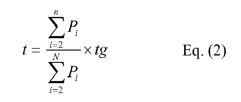
- The foregoing t is a time at which a response starts. As for an actual time, when the case in which a time is 12:00 and t=5, which are designated according to the method of
FIG. 7 is taken as an example, the load operates at a time which is obtained by adding t to 12:00, i.e., 12:05. - The calculation method in the present embodiment is not limited to
FIGS. 9 to 11 or Eqs. (1) and (2), and any method may be employed as long as it can obtain the same results. - In a state in which each load is manipulated according to the command from the power system management operator, an operation opposite to the command is required, that is, when an operation of a load starts according to a request for increasing power consumption, the operation is necessarily terminated. As for order of the opposite operation, the opposite operations may be performed in the order in which the operations start as shown in
FIG. 12A , the opposite operations may be performed in reverse order to the order in which the operations start as shown inFIG. 12A , or the reverse operations may be performed in a random order, regardless of order as shown inFIG. 12C . - In the case of the method of
FIG. 12A , all the loads respond to the same time and request. In the case of the method ofFIG. 12B , priority level for responding to a request may be set, and this method is valid for a device which has a low priority level with respect to a response and which wants to respond within a short time. - The foregoing respective calculation methods are examples of the present embodiment and the present disclosure is not limited to the respective methods; any method may be employed as long as it can obtain the same results. For example, loads to be operated in advance, operation order thereof, and operation intervals are determined, and a consumer inputs a control command to a control device of a first load. Thereafter, when a different load control device detects that the first load starts to operate, by the
monitoring unit 203, the second or subsequent load may automatically operate. - According to the present embodiment, as shown in
FIGS. 9 to 11 , the loads are prevented from operating simultaneously the instant, or immediately thereafter, a designated time arrives; electricity demand may be reduced to a variation with which theplant 12 managed and operated by thesystem management device 11 for supplying electricity to thepower system 13 can sufficiently respond; and a load change can be restrained to below coordination of an electric generator, such that a degradation of power quality can be restrained. -
FIG. 13 is a block diagram showing an overall configuration of a second embodiment of the present disclosure. - In the present embodiment, the
consumer 14 includes theEMS 15 and communicates with theload control devices 24a-24n of therespective loads 23a-23n from thesystem management device 11 and theEMS 15. - As shown in
FIG. 14 , theEMS 15 according to the present embodiment includes amonitoring unit 103 for monitoring an operation state ofdifferent loads 23a-23n and acalculation unit 104 for calculating an operation time of eachload 23a-23n, in addition to thereception unit 101 and theoutput unit 102 for a control command installed in the first embodiment. That is, in the present embodiment, themonitoring unit 203 and thecalculation unit 204, which are installed in eachload control device 24a-24n installed in the first embodiment, are integrated into theEMS 15. - The operation of the present embodiment will be described with reference to the flow chart illustrated in
FIG. 15 . In the present embodiment, a control command for requesting an increase or decrease in power demand is transmitted to theEMS 15 of theconsumer 14 from the system management operator. TheEMS 15 receives the command by the receiving unit 101 (step 1) and checks an operation state of eachload 23a-23n by the monitoring unit 203 (step 2). Thereafter, thecalculation unit 104 calculates an operation time by any one of the various methods as described above in the first embodiment (step 3). The operation time of eachload 23a-23n as a calculation result of thecalculation unit 104 is transmitted to eachload control device 24a-24n by way of the output unit 102 (step 4). - Meanwhile, when the
EMS 15 constantly recognizes an operation state of eachload 23a-23n, "checking of information of each load" instep 2 may be eliminated. - Next, an operation of each
load control device 24a-24n will be described with reference toFIG. 16 . - Each
load control device 24a-24n receives an operation time thereof by the communication unit 201 (step 1). When an operation time has not yet arrived (NO in step 2), eachload control device 24a-24n waits for a certain time (step 3), and then, the process returns to step 2. - In the interim, the
EMS 15 repeatedly performs the process of checking information regarding a different load again, and when a different load receives a manipulation, theEMS 15 recalculates an operation time based on the information. Thus, if the operation time does not arrive yet, the operation time is updated whenever the number ofload control device 24a-24n to which a control command is input is increased. This is the same as the first embodiment. However, when theEMS 15 recognizes which of theloads 23a-23n is a control target in advance, since the number of loads is not changed, an operation time of eachload 23a-23n is also determined by an initial calculation. In this case, eachload control device 24a-24n waits until the initially received operation time arrives. - A load as a control target may be registered in advance in the
EMS 15 and the same load may be a control target each time, or a target load may be checked whenever a control command is received. - Meanwhile, after the operation time calculated by the
EMS 15 is received, when the operation time arrives (YES in step 2), eachload control device 24a-24n operates theloads 23a-23n according to a control command such as a limitation or an increase of designated power in theconsumer 14 by the device controller 205 (step 4). - According to the present embodiment, like the first embodiment, the loads are prevented from operating simultaneously the instant, or immediately thereafter, the designated time arrives. In addition, compared to the first embodiment, the configuration of each
load control device 24a-24n is simplified and it is not required that eachload control device 24a-24n calculates an operation time and transmits the calculation result to differentload control devices 24a-24n. Also, since automatic controlling is performed by theEMS 15, inputting a control command to eachload control device 24a-24n by theconsumer 14 is not necessary, and thus, the operation of eachload 23a-23n can be reliably performed at an appropriate timing. - A third embodiment will be described with reference to
FIGS. 17 and18 . In the third embodiment, an operation time calculation unit of eachload 23a-23n is installed in thesystem management device 11. Thus, as shown inFIG. 17 , thesystem management device 11 is connected to eachload control device 24a-24n of theconsumer 14 by thecommunication line 50, and eachconsumer 14 does not have anEMS 15 as in the second embodiment. - As shown in
FIG. 18 , thesystem management device 11 of the present embodiment includes amonitoring unit 303 for monitoring an operation state of eachload control device 24a-24n of each consumer and acalculation unit 304 for calculating an operation time of eachload 23a-23n, in addition to theinput unit 301 and theoutput unit 302 of a control command. That is, in the present embodiment, themonitoring unit 203 and thecalculation unit 204 installed in eachload control device 24a-24n in the first embodiment are integrated in thesystem management device 11. - An operation of the present embodiment will be described with reference to a flow chart illustrated in
FIG. 19 . In the present embodiment, when a control command requesting an increase or decrease of power demand is inputted to theinput unit 301 of thesystem management device 11 from the system management operator, thesystem management device 11 checks information regarding eachload 23a-23n in the load state monitoring unit 303 (step 1). - That is, when information regarding which of the
loads 23a-23n theconsumer 14 is to execute a control command, information regarding what order theconsumer 14 operates the loads, and the like are stored in eachload control device 24a-24n, such information is obtained from eachload control device 24a-24n. Simultaneously, an operation state of eachload 23a-23n is recognized from thepower measurement unit 202 installed in eachload control device 24a-24n. In this case, when such information has been previously transmitted to thesystem management device 11 from eachconsumer 14, "checking of information of each load" instep 1 may be eliminated. - After the state of each
load 23a-23n is checked, thecalculation unit 304 of thesystem management device 11 calculates an operation time of eachload 23a-23n by any one of the various methods as described above in the first embodiment (step 2). The calculation result obtained by thecalculation unit 304 is transmitted to eachload control device 24a-24n by way of the output unit 302 (step 3). - Upon receipt of the result, each
load control device 24a-24n executes an operation such as decreasing or increasing power at a designated time with respect to eachload 23a-23n managed by itself. In this case, the process is the same as the flow chart illustrated inFIG. 16 of the second embodiment. - In the present embodiment, processing without consideration of the operation status of each
load 23a-23n may also be possible. In this case, the "checking of information regarding each load" described inFIG. 19 is omitted, and an operation time is calculated on the assumption that all the loads as requested targets are stopped or in operation. - For example, when a command for increasing power consumption is issued, an operation time is calculated on the assumption that the
loads 23a-23n as requested targets are all stopped. Then, the result is transmitted to theloads 23a-23n, and when a target load is stopped, the load transitions from the stop state to an operation state in response to the request signal, and when a target load is in operation, a response is not made despite receiving a request signal, since the target load is already in operation. - According to the present embodiment, besides the obtaining of the effect like that of the first embodiment, the configuration of the respective loads and control devices is simplified more than those of the first embodiment. Also, there is no need to install the
EMS 15 in every consumer. In addition, since all information and the calculation unit is integrated in thesystem management device 11 and every load is operated according to the intention of the system management operator, a degradation of power quality can be further restrained. - A fourth embodiment will be described with reference to
FIG. 20 . In the present embodiment, thesystem management device 11 and theEMS 15 are eliminated, and a control command from the system management operator is transmitted to theconsumer 14 through a phone, mail, facsimile, written notification, such as documents, or the like, and based on the control command, theconsumer 14 directly inputs a control command to eachload control device 24a-24n. - As shown in
FIG. 21 , eachload control device 24a-24n of the present embodiment is connected to aninput device 400, such as a keyboard, a storage device, etc., manipulated by theconsumer 14. Eachload control device 24a-24n includes an operationtime setting unit 401 connected to theinput device 400 and an operationtime calculation unit 402 connected to the operationtime setting unit 401. When theconsumer 14 inputs a designated time in a control command to thesetting unit 401, thecalculation time 402 calculates an operation time of eachload 23a-23n based on the designated time. - As a calculation method of the
calculation unit 402, a method that does not refer to a state of a different load, among the calculation methods described in the respective embodiments, may be used. For example, a method of setting a random number in each device until a product is launched, and employing a time obtained by adding the random number to an operation designated time, as an operation time, may be used. Also, an operation time unique to a load may be set until a product is launched without setting it to the consumer. In this case, the set operation time is distributed within tg so as to avoid simultaneous operations. Further, the present embodiment is not limited to the foregoing method and any method may be employed as long as a set value is automatically corrected to prevent simultaneous operations. - In the present embodiment, an operation time is set in advance in each
load 23a-23n, and when the operation time arrives, eachload 23a-23n is operated. In this case, the time set by theconsumer 14 is automatically corrected by thecalculation unit 403 installed in eachload control device 24a-24n such that it is different for eachload 23a-23n. Accordingly, the plurality of loads can be prevented from operating simultaneously. - This embodiment is valid when operated, in particular, at a determined day and time, such as 11:00 to 13:00 on weekdays. In addition, according to the present embodiment, the system configuration is simpler in comparison to the foregoing respective embodiments.
- A fifth embodiment will be described with reference to
FIGS. 22 to 25 . In the present embodiment, some or all of theloads 23a-23n are configured as loads and capacitor devices for storing or discharging power in any one of the first to fourth embodiments.FIG. 22 shows an application of the fifth embodiment to the configuration in which theEMS 15 of the second embodiment is installed in eachconsumer 14, but the fifth embodiment is not limited toFIG. 22 . - The load and capacitor devices may include an emergency capacitor device installed in homes, hospitals, plants or the like, or a capacitor device which serves as a load in case of charging and outputs power charged in a battery to a consumer or a system in case of discharging, such as an electric automotive, or houses or plants having a photovoltaic generating panel and a capacitor device.
- In the fifth embodiment, the
power measurement unit 202 may measure a power usage amount of the load and capacitor device, an amount of charging or discharging power, or a power storage amount of the capacitor device, as necessary. Also, thedevice controller 205 of eachload control device 24a-24n includes aload operation controller 205a and a charge/discharge controller 205b of the capacitor device. The charge/discharge controller 205 controls the capacitor device based on each operation time set by thecalculation unit 104 of theEMS 15 as a start point, as follows. - (1) As shown in
FIG. 24 , in order to make a gentle power flow of connection points with thepower system 13 from ts to te, an amount of discharge of the capacitor device is controlled such that the amount of discharge is increased when eachload 23a-23n starts to operate, and then, sequentially reduced when subsequent loads start to operate to obtain an uneven saw-tooth stripe shape from ts to te. - (2) As shown in
FIG. 25 , only an output of the capacitor device is gently reduced between ts at which the first load starts to operate and te at which an operation of the last load is completed. In such case, a power flow at the connection points has a stepwise shape from ts to te. - According to the present embodiment, an operation start time of each
load 23a-23n can be slightly moved, and the following operational effects can be obtained by controlling charging and discharging of the capacitor device. - For example, according to (1), a difference between power demand changing stepwise due to operations of different devices and an output command value having a gentle flow of connection points can be supplemented by an output of a device that can store or discharge power, whereby the flow of the connection points can have a sloped shape. In (2), by allowing only an output of a device that can store or discharge power to have a sloped shape, a variation due to the device that can store or discharge power can be reduced.
- As described above, according to the present embodiment, the capacitor device capable of storing or discharging power can be used to further restrain a change, in addition to the effects of the foregoing respective embodiments.
- A sixth embodiment will be described with reference to
FIGS. 26 to 29 . In this embodiment, a generating device is installed by addingloads 23a-23n to apower line 16 extending from asystem 13 in any one of the first to fifth embodiments.FIG. 26 shows an application of the present embodiment to the configuration in which theEMS 15 is installed in eachconsumer 14, but the present embodiment is not limited toFIG. 26 . - A
photovoltaic generating device 25a, agas engine generator 25b, a water-turbine generator, a wind generator, or the like may be used as the generating device.Generation control devices 26a-26n are installed in therespective generating devices 25a-25n. As shown inFIG. 27 , thegenerating devices 25a-25n include acommunication unit 501 for communicating with theEMS 15, apower measurement unit 502 for detecting an operation state of thegenerating devices 25a-25n, and adevice controller 504. Thedevice controller 504 controls the operation of therespective generating devices 25a-25n based on an operation time transmitted from the operationtime calculation unit 104 of theEMS 15. - In case of a generator in which an output can be freely changed, such as a gas engine generator or the like, a variation can be reduced by gently changing an output, like the device which can store or discharge power as described in the fifth embodiment.
- Specifically, a flow of connection points can have a sloped shape by supplementing a difference with the output command value such as the case in which the flow of the connection points is gentle, as shown in
FIG. 28 , by an output of the generating device, or a variation of power in case of starting an operation of decreasing or increasing a plurality of loads is reduced by making only an output of the generating device have a sloped shape as shown inFIG. 29 . This may be an operation of adding a bias to the output of the device that can store or discharge power as described in the fifth embodiment. - Meanwhile, the generator whose output cannot be freely changed, like the photovoltaic generating device, basically has a movement like the
loads 23a-23n described in the first to fourth embodiments. A generator whose output cannot be freely changed refers to a generator uncertain about obtaining a desired output, but even for this generator, power desired to be initially generated can be reduced through controlling. That is, in case of a combination of a device whose power consumption is increased as an operation starts or as an output is increased and a device whose supply power is reduced as an operation is stopped or an output is reduced, the devices can be simultaneously operated. - For example, when a command for increasing a load is received from the power system management operator, a new load consuming power is operated or loads are operated to increase output and, simultaneously, an output of a generator whose output cannot be freely changed is limitedly reduced. Here, in the first to fourth embodiments, a single operation is performed basically, but in case of the combination of the load consuming power and the device generating power as in the present embodiment, since variations according to operations are canceled out, they can be simultaneously manipulated.
- In other words, in case of calculating an operation time, an operation time is calculated excluding the generating device, and thereafter, the device may be operated at a certain timing included in a plurality of calculated operation times. When the devices are simultaneously operated, a variation corresponding to a single operation can be reduced.
- According to the present embodiment, the device for generating power can be used in addition to the effects of the respective embodiments and, thus, a more flexible system can be established.
- A seventh embodiment will be described with reference to
FIG. 30 . In the present embodiment, the operation time is calculated while considering power rates in any one of the first to sixth embodiments.FIG. 30 shows an application of the present embodiment to the configuration in which theEMS 15 is installed in eachconsumer 14, but the present embodiment is not limited toFIG. 30 . - To this end, in the present embodiment, a power
rate storage unit 105 is installed in theEMS 15, and power rates regarding therespective loads 23a-23n are stored in thestorage unit 105. Since power rates are different according to a power usage time or a season, such as midnight electric power, seasonal power or the like, an operationtime storage unit 106 for storing an operation schedule time of eachload 23a-23n is installed. In addition, an operationtime calculation unit 104 calculates an operation time of eachload 23a-23n while considering a power rate and an operation time as described hereinafter, in addition to information regarding an operational state of eachload 23a-23n or the presence or absence of a control command. - For example, when a power rate is changed over time, a consumer may suffer from a disadvantage as a load does not operate at a scheduled time. In order to prevent this, in the present embodiment, an operation time is calculated as follows.
- First, a temporary operation time is calculated according to Eqs. (1) and (2) described in the first embodiment. And it is assumed that a power rate before the time tc at which the power rate is changed is Pp, and a power rate after the tc is Pa. Here, it is assumed that five devices respond, power consumption of the
loads 23a-23e is Xa-Xe, and a temporary response time is Ta-Te. - In
FIG. 31 , in a portion (1), the loads are operated early during a time duration in which a power rate is high, and in a portion (2), the loads are operated late during a time duration in which the power rate is low. That is, in (1), the power rate is higher than the case in which the loads are operated simultaneously, and in (2), the power rate is lower than the case in which the loads are operated simultaneously because a time duration in which the loads are operated is shortened. - The sums of power rates are equal before and after the power rates are changed, when a value obtained by multiplying Pp to the area of (1) and a value obtained by multiplying Pa to the area of (2) are equal. Thus, the difference between the two is made to 0 by delaying a response time by a time t while maintaining the time interval of the temporary response time Ta-Te.
- A power rate of the device which respond before the power rate is changed may be expressed by Eq. (3) below:

- A power rate of the device which respond after the power rate is changed may be expressed by Eq. (4) below:

- The correction time t can be obtained by solving an equation of (3)=(4). And then, t is added to the temporary response time Ta-Te to correct it to obtain a formal response time. Also, when a load responds, the reverse operation is executed. Also, in such case, the same calculation as described above can be executed to correct a response time.
- According to the foregoing method, a power rate difference is gone whenever each operation is performed, but it is also possible that a power rate difference is generated at each time as a constraint condition that a power rate difference is gone within a certain period of time like, for example, a week, and the power rate difference becomes 0 up to the last time of the period.
- According to the present embodiment having the foregoing configuration, a disadvantage of paying a higher rate than a power rate determined in the related art can be avoided despite the power rate being changed over time, and the effects of the respective embodiments is also obtained.
- The present disclosure is not limited to the respective embodiments but also include the following embodiments.
- (1) In the foregoing respective embodiments, the present disclosure is described as a system for controlling an operation of an electric device, but a program for functioning the operation control method executed in the present system, or a computer as an operation control device of an electric device, is also an aspect of the present disclosure.
- (2) When a plurality of consumers are integrated, the consumers may be grouped such that demand for power loads is equal in each group, the configuration of a power device is equal in each group, or the characteristics of the loads are equal in each group.
- (3) The
system management device 11, theEMS 15, theload control devices 24a-24n, and thegenerating devices 25a-25n may be configured to be divided as long as the same function can be obtained. - (4) The present disclosure is not limited to the foregoing embodiments, and the components may be modified to be embodied within a range that does not divert from the gist of the present disclosure in an implementation stage. Also, various inventions may be formed by appropriately combining a plurality of components disclosed in the foregoing embodiments.
For example, some of the components disclosed in the embodiments may be deleted. In addition, components of other embodiments may be appropriately combined. - While certain embodiments have been described, these embodiments have been presented by way of example only, and are not intended to limit the scope of the disclosures. Indeed, the novel methods and apparatuses described herein may be embodied in a variety of other forms; furthermore, various omissions, substitutions and changes in the form of the embodiments described herein may be made without departing from the spirit of the disclosures. The accompanying claims and their equivalents are intended to cover such forms or modifications as would fall within the scope and spirit of the disclosures.
Claims (12)
- A system for controlling an electric device operation comprising a plurality of electric devices managed by a consumer associated with a power system and a plurality of control devices for controlling an operation of the electric devices, the system comprising:an operation time calculation unit configured to calculate a start time of an operation of increasing or decreasing power received from the plurality of electric devices based on a control command for requesting an increase or decrease of power received from the power system such that the start time is different for each of the electric devices,wherein each of the control devices executes an operation of increasing or decreasing reception power at an operation start time different for each of the electric devices as a result of calculation of the calculation unit.
- The system of Claim 1, wherein each of the control devices comprises:a communication unit configured to exchange information with a different electric device;an operation state monitoring unit configured to monitor an operation state of the different electric device and/or an input state of a control command of the different electric device; anda calculation unit configured to calculate an operation time of each of the electric devices based on the information obtained from the monitoring unit and the control command.
- The system of Claim 1, wherein the consumer comprises an energy management device for managing an operation of the plurality of electric devices, and
wherein the energy management device comprises:a communication unit configured to exchange information between the respective electric devices;an operation state monitoring unit configured to monitor an operation state of the respective electric devices and/or an input state of the control command of each of the electric devices; anda calculation unit configured to calculate an operation time of each of the electric devices based on the information obtained from the monitoring unit and the control command. - The system of Claim 1, wherein a system management device for controlling an operation of each of the electric devices connected to the power system is installed in the power system, and
wherein the system management device comprises:a communication unit configured to exchange information between the respective electric devices;an operation state monitoring unit configured to monitor an operation state of each of the electric devices and/or an input state of the control command of each of the electric devices; anda calculation unit configured to calculate an operation time of each of the electric devices based on the information obtained from the monitoring unit and the control command. - The system of Claim 1, wherein each of the control devices comprises:an operation time setting unit configured to input a control command to each of the electric devices by a consumer; anda calculation unit configured to calculate an operation time of each of the electric devices based on the control command input to the operation time setting unit.
- The system of any one of Claims 1 to 5, wherein:at least one of the electric devices is configured as a load and a capacitor device,the control device comprises a load operation controller and a capacitor device operation controller,the operation time calculation unit calculates an operation start time of the load and the capacitor device based on the control command, andthe load operation controller and the capacitor device operation controller control an operation of the load and the capacitor device based on the calculation result.
- The system of any one of Claims 1 to 6, wherein a generating device is connected together with the electric device to the power system, and
wherein the generating device comprises a generation control device configured to control an operation of the generating device, and
the operation time calculation unit calculates an operation start time of the electric device and an operation control time of the generating device based on the control command, and an operation controller of the electric device and an operation controller of the generating control device control an operation of the electric device and the generating device based on the calculation result. - The system of any one of Claims 1 to 7, wherein the operation time calculation unit comprises an operation time storage unit and a power rate storage unit of each of the electric devices, and calculates an operation time of each of the electric devices based on a power rate stored in the power rate storage unit.
- A method for controlling an electric device operation comprising a plurality of electric devices managed by a consumer associated with a power system and a plurality of control device for controlling an operation of the electric devices, the method comprising:calculating a start time of an operation of increasing or decreasing power received from the plurality of electric devices based on a control command for requesting an increase or decrease of power received from the power system such that it is different for each of the electric devices; andexecuting, by the control device of each of the electric devices, an operation of increasing or decreasing reception power at an operation start time different for each of the electric devices as a result of calculation of a calculation unit.
- The method of Claim 9, wherein at least one of the electric devices is configured as a load and a capacitor device, the method further comprising:calculating an operation start time of the load and the capacitor device based on the control command by the operation time calculation unit; andcontrolling an operation of the load and the capacitor device based on the calculation result by a load operation controller and a capacitor device operation controller.
- The method of Claim 9 or 10, wherein a generating device is connected together with the electric device to the power system, and comprises a generation control device configured to control an operation of the generating device, the method further comprising:calculating an operation start time of the electric device and an operation control time of the generating device based on the control command by the operation time calculation unit; andcontrolling an operation of the electric device and the generating device based on the calculation result by an operation controller of the electric device and the operation controller of the generation control device.
- The method of any one of Claims 9 to 11, wherein the operation time calculation unit comprises an operation time storage unit and a power rate storage unit of each of the electric devices, and
wherein the method comprises calculating an operation time of each of the electric devices based on a power rate stored in the power rate storage unit by the calculation unit.
Applications Claiming Priority (1)
| Application Number | Priority Date | Filing Date | Title |
|---|---|---|---|
| JP2011281944A JP5917132B2 (en) | 2011-12-22 | 2011-12-22 | Electric equipment operation control system and method |
Publications (3)
| Publication Number | Publication Date |
|---|---|
| EP2608349A2 true EP2608349A2 (en) | 2013-06-26 |
| EP2608349A3 EP2608349A3 (en) | 2016-08-10 |
| EP2608349B1 EP2608349B1 (en) | 2018-07-25 |
Family
ID=47428482
Family Applications (1)
| Application Number | Title | Priority Date | Filing Date |
|---|---|---|---|
| EP12193610.8A Active EP2608349B1 (en) | 2011-12-22 | 2012-11-21 | System and method of controlling operation of electric device |
Country Status (4)
| Country | Link |
|---|---|
| US (1) | US20130162039A1 (en) |
| EP (1) | EP2608349B1 (en) |
| JP (1) | JP5917132B2 (en) |
| CN (1) | CN103178614A (en) |
Families Citing this family (5)
| Publication number | Priority date | Publication date | Assignee | Title |
|---|---|---|---|---|
| DE102012020621A1 (en) * | 2011-11-15 | 2013-05-16 | Heidelberger Druckmaschinen Ag | Process for the delivery of electrical power to power sensors of a printing machine |
| JP2016025752A (en) * | 2014-07-18 | 2016-02-08 | 株式会社東芝 | Control apparatus, control method and computer program |
| JP2016123241A (en) * | 2014-12-25 | 2016-07-07 | 株式会社村田製作所 | Power conditioner |
| JP6610059B2 (en) * | 2015-07-29 | 2019-11-27 | 富士電機株式会社 | Electric power demand induction device |
| CN109447482B (en) * | 2018-11-01 | 2021-10-08 | 积成电子股份有限公司 | Intelligent substation sequence control double-confirmation implementation method |
Citations (1)
| Publication number | Priority date | Publication date | Assignee | Title |
|---|---|---|---|---|
| JP2006203959A (en) | 2005-01-18 | 2006-08-03 | Chugoku Electric Power Co Inc:The | Power demand and supply adjusting system |
Family Cites Families (36)
| Publication number | Priority date | Publication date | Assignee | Title |
|---|---|---|---|---|
| US5462225A (en) * | 1994-02-04 | 1995-10-31 | Scientific-Atlanta, Inc. | Apparatus and method for controlling distribution of electrical energy to a space conditioning load |
| EP1701425A3 (en) * | 1999-11-24 | 2011-01-05 | American Superconductor Corporation | Voltage regulation of a utility power network |
| JP4547776B2 (en) * | 2000-06-19 | 2010-09-22 | ダイキン工業株式会社 | Demand control system for electric equipment, demand control method, demand control management apparatus, and demand control management method |
| KR20040083514A (en) * | 2002-02-14 | 2004-10-02 | 얀마 가부시키가이샤 | Power source switching unit and power source management system comprising it |
| JP2003294291A (en) * | 2002-04-01 | 2003-10-15 | Minoru Denki Koji:Kk | Power saving device for electromechanical instrument |
| JP2003299264A (en) * | 2002-04-02 | 2003-10-17 | Hitachi Ltd | Coordinated power control system for electric apparatus |
| EP1462915A3 (en) * | 2003-03-26 | 2009-01-21 | Panasonic Corporation | Clock controlling method and apparatus |
| US7149605B2 (en) * | 2003-06-13 | 2006-12-12 | Battelle Memorial Institute | Electrical power distribution control methods, electrical energy demand monitoring methods, and power management devices |
| CN1590742A (en) * | 2003-08-29 | 2005-03-09 | 松下电器产业株式会社 | Cogeneration system, operation controller for cogeneration facility, and operation program for cogeneration facility |
| JP4161854B2 (en) * | 2003-09-02 | 2008-10-08 | ソニー株式会社 | Battery remaining capacity calculation method, battery remaining capacity calculation device, and battery remaining capacity calculation program |
| EP1533893A3 (en) * | 2003-11-19 | 2014-07-02 | Panasonic Corporation | Generator control system, generating apparatus control method, program and record medium |
| JP4552119B2 (en) * | 2004-07-16 | 2010-09-29 | 清水建設株式会社 | Multi air conditioner demand control system |
| US7444096B2 (en) * | 2005-03-29 | 2008-10-28 | Hewlett-Packard Development Company, L.P. | Electronic device power supply |
| JP4584819B2 (en) * | 2005-12-08 | 2010-11-24 | 株式会社日立製作所 | Load monitoring control method and system |
| JP4578396B2 (en) * | 2005-12-08 | 2010-11-10 | 株式会社日立超エル・エス・アイ・システムズ | Information processing device |
| JP4929783B2 (en) * | 2006-03-27 | 2012-05-09 | 富士通株式会社 | Power monitoring device |
| JP4753118B2 (en) * | 2006-06-13 | 2011-08-24 | 独立行政法人産業技術総合研究所 | Energy supply and demand adjustment system |
| JP5288782B2 (en) * | 2007-03-09 | 2013-09-11 | 三洋電機株式会社 | Demand control system, demand controller, demand program, and demand control method |
| TW200917014A (en) * | 2007-10-15 | 2009-04-16 | Andyson Internat Co Ltd | Sectional start-up timing control method |
| US7853365B2 (en) * | 2008-04-30 | 2010-12-14 | Kabushiki Kaisha Toshiba | Optimal load distributing system |
| US9007024B2 (en) * | 2008-05-28 | 2015-04-14 | American Reliance, Inc. | DC power control to maximize battery charging time |
| JP4737784B2 (en) * | 2008-12-24 | 2011-08-03 | 東芝ストレージデバイス株式会社 | Magnetic storage device inspection device, magnetic storage device and manufacturing method thereof |
| JP4710982B2 (en) * | 2009-01-26 | 2011-06-29 | ダイキン工業株式会社 | Demand control apparatus, demand control system, and demand control program |
| JP2010226942A (en) * | 2009-02-26 | 2010-10-07 | Sanyo Electric Co Ltd | Grid interconnection device, grid interconnection system, and power control system |
| CA2734712A1 (en) * | 2009-03-23 | 2010-09-30 | Panasonic Corporation | Energy supply system |
| WO2010109782A1 (en) * | 2009-03-23 | 2010-09-30 | パナソニック株式会社 | Energy supply system |
| KR100919504B1 (en) * | 2009-03-25 | 2009-09-28 | 주식회사 피엠디네트웍스 | Power regulator and apparatus for controlling power remote |
| JP5523733B2 (en) * | 2009-04-21 | 2014-06-18 | ルネサスエレクトロニクス株式会社 | Power supply control device and power supply control method |
| KR101595391B1 (en) * | 2009-10-26 | 2016-02-18 | 엘지전자 주식회사 | Apparatus for controlling washing machine and method the same |
| CN101777765B (en) * | 2010-01-27 | 2012-06-20 | 中国电力科学研究院 | On-line load simulation method of power system |
| KR101702838B1 (en) * | 2010-02-19 | 2017-02-07 | 삼성전자주식회사 | Demand response method and system the same |
| EP2375527B1 (en) * | 2010-04-12 | 2018-09-19 | Samsung Electronics Co., Ltd. | Demand Response Method and Demand Response System |
| JP5646205B2 (en) * | 2010-04-28 | 2014-12-24 | 株式会社東芝 | Power consumption management system, power consumption management device used therefor, power consumption management method, central power supply management device, power supply management method |
| JPWO2011142131A1 (en) * | 2010-05-11 | 2013-07-22 | パナソニック株式会社 | Electrical device control system, server, electrical device, and electrical device control method |
| JP5630176B2 (en) * | 2010-09-16 | 2014-11-26 | ソニー株式会社 | Power supply |
| US8463449B2 (en) * | 2011-01-28 | 2013-06-11 | Dean Sanders | Systems, apparatus, and methods of a solar energy grid integrated system with energy storage appliance |
-
2011
- 2011-12-22 JP JP2011281944A patent/JP5917132B2/en active Active
-
2012
- 2012-11-21 EP EP12193610.8A patent/EP2608349B1/en active Active
- 2012-12-13 US US13/713,843 patent/US20130162039A1/en not_active Abandoned
- 2012-12-20 CN CN2012105574893A patent/CN103178614A/en active Pending
Patent Citations (1)
| Publication number | Priority date | Publication date | Assignee | Title |
|---|---|---|---|---|
| JP2006203959A (en) | 2005-01-18 | 2006-08-03 | Chugoku Electric Power Co Inc:The | Power demand and supply adjusting system |
Also Published As
| Publication number | Publication date |
|---|---|
| JP5917132B2 (en) | 2016-05-11 |
| EP2608349A3 (en) | 2016-08-10 |
| JP2013132187A (en) | 2013-07-04 |
| EP2608349B1 (en) | 2018-07-25 |
| US20130162039A1 (en) | 2013-06-27 |
| CN103178614A (en) | 2013-06-26 |
Similar Documents
| Publication | Publication Date | Title |
|---|---|---|
| EP2608349A2 (en) | System and method of controlling operation of electric device | |
| US9469203B2 (en) | Battery information output equipment for power supply and demand leveling system | |
| US11664661B2 (en) | System and method for controlling an electrical load | |
| US11210747B2 (en) | Systems and methods for randomized, packet-based power management of conditionally-controlled loads and bi-directional distributed energy storage systems | |
| WO2013015191A1 (en) | Startup control method, grid-connected device, and control device | |
| US20120242301A1 (en) | Control apparatus | |
| EP3343720A1 (en) | Management server, management method, and management system | |
| US20140324193A1 (en) | Power control apparatus, power control system, and power control method | |
| JP5858681B2 (en) | Electric vehicle charging system and electric vehicle charging device | |
| JP7185577B2 (en) | Storage battery control system | |
| JP2019047612A (en) | Photovoltaic power generation device and control method of the same | |
| EP3444761A1 (en) | Systems, apparatus, and methods for controlling generating assets, flexible loads and/or storage assets to support dynamic regulation | |
| JP5991228B2 (en) | Power storage device | |
| US11411401B2 (en) | System for reducing load peaks in an electrical installation | |
| JP4417238B2 (en) | Distributed power supply system and distributed power supply system control method | |
| JPWO2017018344A1 (en) | Communication apparatus and communication method | |
| JP2016103890A (en) | Power control unit and power control system | |
| US11972496B2 (en) | Systems and methods for randomized energy draw or supply requests | |
| JP5868254B2 (en) | Power supply system | |
| JP7204560B2 (en) | Storage battery control system | |
| KR101411457B1 (en) | Energy storage system and method for controlling energy storage device | |
| CN115528751A (en) | Energy consumption optimization scheduling method and system for transformer area | |
| KR20170002311A (en) | Energy management scheduling system and method for energy storage system | |
| KR20190021538A (en) | Energy management system based on virtual power plant platform and management method therefor | |
| EP3507130A1 (en) | Intelligent energy charging system |
Legal Events
| Date | Code | Title | Description |
|---|---|---|---|
| 17P | Request for examination filed |
Effective date: 20121121 |
|
| AK | Designated contracting states |
Kind code of ref document: A2 Designated state(s): AL AT BE BG CH CY CZ DE DK EE ES FI FR GB GR HR HU IE IS IT LI LT LU LV MC MK MT NL NO PL PT RO RS SE SI SK SM TR |
|
| AX | Request for extension of the european patent |
Extension state: BA ME |
|
| PUAI | Public reference made under article 153(3) epc to a published international application that has entered the european phase |
Free format text: ORIGINAL CODE: 0009012 |
|
| PUAL | Search report despatched |
Free format text: ORIGINAL CODE: 0009013 |
|
| AK | Designated contracting states |
Kind code of ref document: A3 Designated state(s): AL AT BE BG CH CY CZ DE DK EE ES FI FR GB GR HR HU IE IS IT LI LT LU LV MC MK MT NL NO PL PT RO RS SE SI SK SM TR |
|
| AX | Request for extension of the european patent |
Extension state: BA ME |
|
| RIC1 | Information provided on ipc code assigned before grant |
Ipc: H02J 3/14 20060101AFI20160707BHEP |
|
| GRAP | Despatch of communication of intention to grant a patent |
Free format text: ORIGINAL CODE: EPIDOSNIGR1 |
|
| INTG | Intention to grant announced |
Effective date: 20171222 |
|
| GRAJ | Information related to disapproval of communication of intention to grant by the applicant or resumption of examination proceedings by the epo deleted |
Free format text: ORIGINAL CODE: EPIDOSDIGR1 |
|
| GRAP | Despatch of communication of intention to grant a patent |
Free format text: ORIGINAL CODE: EPIDOSNIGR1 |
|
| INTC | Intention to grant announced (deleted) | ||
| GRAS | Grant fee paid |
Free format text: ORIGINAL CODE: EPIDOSNIGR3 |
|
| INTG | Intention to grant announced |
Effective date: 20180524 |
|
| GRAA | (expected) grant |
Free format text: ORIGINAL CODE: 0009210 |
|
| AK | Designated contracting states |
Kind code of ref document: B1 Designated state(s): AL AT BE BG CH CY CZ DE DK EE ES FI FR GB GR HR HU IE IS IT LI LT LU LV MC MK MT NL NO PL PT RO RS SE SI SK SM TR |
|
| REG | Reference to a national code |
Ref country code: GB Ref legal event code: FG4D |
|
| REG | Reference to a national code |
Ref country code: CH Ref legal event code: EP |
|
| REG | Reference to a national code |
Ref country code: AT Ref legal event code: REF Ref document number: 1022793 Country of ref document: AT Kind code of ref document: T Effective date: 20180815 |
|
| REG | Reference to a national code |
Ref country code: IE Ref legal event code: FG4D |
|
| REG | Reference to a national code |
Ref country code: DE Ref legal event code: R096 Ref document number: 602012048809 Country of ref document: DE |
|
| REG | Reference to a national code |
Ref country code: FR Ref legal event code: PLFP Year of fee payment: 7 |
|
| REG | Reference to a national code |
Ref country code: NL Ref legal event code: MP Effective date: 20180725 |
|
| REG | Reference to a national code |
Ref country code: LT Ref legal event code: MG4D |
|
| PG25 | Lapsed in a contracting state [announced via postgrant information from national office to epo] |
Ref country code: NL Free format text: LAPSE BECAUSE OF FAILURE TO SUBMIT A TRANSLATION OF THE DESCRIPTION OR TO PAY THE FEE WITHIN THE PRESCRIBED TIME-LIMIT Effective date: 20180725 |
|
| REG | Reference to a national code |
Ref country code: AT Ref legal event code: MK05 Ref document number: 1022793 Country of ref document: AT Kind code of ref document: T Effective date: 20180725 |
|
| PG25 | Lapsed in a contracting state [announced via postgrant information from national office to epo] |
Ref country code: FI Free format text: LAPSE BECAUSE OF FAILURE TO SUBMIT A TRANSLATION OF THE DESCRIPTION OR TO PAY THE FEE WITHIN THE PRESCRIBED TIME-LIMIT Effective date: 20180725 Ref country code: PL Free format text: LAPSE BECAUSE OF FAILURE TO SUBMIT A TRANSLATION OF THE DESCRIPTION OR TO PAY THE FEE WITHIN THE PRESCRIBED TIME-LIMIT Effective date: 20180725 Ref country code: AT Free format text: LAPSE BECAUSE OF FAILURE TO SUBMIT A TRANSLATION OF THE DESCRIPTION OR TO PAY THE FEE WITHIN THE PRESCRIBED TIME-LIMIT Effective date: 20180725 Ref country code: BG Free format text: LAPSE BECAUSE OF FAILURE TO SUBMIT A TRANSLATION OF THE DESCRIPTION OR TO PAY THE FEE WITHIN THE PRESCRIBED TIME-LIMIT Effective date: 20181025 Ref country code: SE Free format text: LAPSE BECAUSE OF FAILURE TO SUBMIT A TRANSLATION OF THE DESCRIPTION OR TO PAY THE FEE WITHIN THE PRESCRIBED TIME-LIMIT Effective date: 20180725 Ref country code: IS Free format text: LAPSE BECAUSE OF FAILURE TO SUBMIT A TRANSLATION OF THE DESCRIPTION OR TO PAY THE FEE WITHIN THE PRESCRIBED TIME-LIMIT Effective date: 20181125 Ref country code: NO Free format text: LAPSE BECAUSE OF FAILURE TO SUBMIT A TRANSLATION OF THE DESCRIPTION OR TO PAY THE FEE WITHIN THE PRESCRIBED TIME-LIMIT Effective date: 20181025 Ref country code: LT Free format text: LAPSE BECAUSE OF FAILURE TO SUBMIT A TRANSLATION OF THE DESCRIPTION OR TO PAY THE FEE WITHIN THE PRESCRIBED TIME-LIMIT Effective date: 20180725 Ref country code: GR Free format text: LAPSE BECAUSE OF FAILURE TO SUBMIT A TRANSLATION OF THE DESCRIPTION OR TO PAY THE FEE WITHIN THE PRESCRIBED TIME-LIMIT Effective date: 20181026 Ref country code: RS Free format text: LAPSE BECAUSE OF FAILURE TO SUBMIT A TRANSLATION OF THE DESCRIPTION OR TO PAY THE FEE WITHIN THE PRESCRIBED TIME-LIMIT Effective date: 20180725 |
|
| PG25 | Lapsed in a contracting state [announced via postgrant information from national office to epo] |
Ref country code: HR Free format text: LAPSE BECAUSE OF FAILURE TO SUBMIT A TRANSLATION OF THE DESCRIPTION OR TO PAY THE FEE WITHIN THE PRESCRIBED TIME-LIMIT Effective date: 20180725 Ref country code: LV Free format text: LAPSE BECAUSE OF FAILURE TO SUBMIT A TRANSLATION OF THE DESCRIPTION OR TO PAY THE FEE WITHIN THE PRESCRIBED TIME-LIMIT Effective date: 20180725 Ref country code: AL Free format text: LAPSE BECAUSE OF FAILURE TO SUBMIT A TRANSLATION OF THE DESCRIPTION OR TO PAY THE FEE WITHIN THE PRESCRIBED TIME-LIMIT Effective date: 20180725 |
|
| REG | Reference to a national code |
Ref country code: DE Ref legal event code: R097 Ref document number: 602012048809 Country of ref document: DE |
|
| PG25 | Lapsed in a contracting state [announced via postgrant information from national office to epo] |
Ref country code: ES Free format text: LAPSE BECAUSE OF FAILURE TO SUBMIT A TRANSLATION OF THE DESCRIPTION OR TO PAY THE FEE WITHIN THE PRESCRIBED TIME-LIMIT Effective date: 20180725 Ref country code: CZ Free format text: LAPSE BECAUSE OF FAILURE TO SUBMIT A TRANSLATION OF THE DESCRIPTION OR TO PAY THE FEE WITHIN THE PRESCRIBED TIME-LIMIT Effective date: 20180725 Ref country code: EE Free format text: LAPSE BECAUSE OF FAILURE TO SUBMIT A TRANSLATION OF THE DESCRIPTION OR TO PAY THE FEE WITHIN THE PRESCRIBED TIME-LIMIT Effective date: 20180725 Ref country code: RO Free format text: LAPSE BECAUSE OF FAILURE TO SUBMIT A TRANSLATION OF THE DESCRIPTION OR TO PAY THE FEE WITHIN THE PRESCRIBED TIME-LIMIT Effective date: 20180725 |
|
| PG25 | Lapsed in a contracting state [announced via postgrant information from national office to epo] |
Ref country code: SM Free format text: LAPSE BECAUSE OF FAILURE TO SUBMIT A TRANSLATION OF THE DESCRIPTION OR TO PAY THE FEE WITHIN THE PRESCRIBED TIME-LIMIT Effective date: 20180725 Ref country code: DK Free format text: LAPSE BECAUSE OF FAILURE TO SUBMIT A TRANSLATION OF THE DESCRIPTION OR TO PAY THE FEE WITHIN THE PRESCRIBED TIME-LIMIT Effective date: 20180725 Ref country code: SK Free format text: LAPSE BECAUSE OF FAILURE TO SUBMIT A TRANSLATION OF THE DESCRIPTION OR TO PAY THE FEE WITHIN THE PRESCRIBED TIME-LIMIT Effective date: 20180725 |
|
| PLBE | No opposition filed within time limit |
Free format text: ORIGINAL CODE: 0009261 |
|
| STAA | Information on the status of an ep patent application or granted ep patent |
Free format text: STATUS: NO OPPOSITION FILED WITHIN TIME LIMIT |
|
| REG | Reference to a national code |
Ref country code: CH Ref legal event code: PL |
|
| 26N | No opposition filed |
Effective date: 20190426 |
|
| GBPC | Gb: european patent ceased through non-payment of renewal fee |
Effective date: 20181121 |
|
| PG25 | Lapsed in a contracting state [announced via postgrant information from national office to epo] |
Ref country code: MC Free format text: LAPSE BECAUSE OF FAILURE TO SUBMIT A TRANSLATION OF THE DESCRIPTION OR TO PAY THE FEE WITHIN THE PRESCRIBED TIME-LIMIT Effective date: 20180725 Ref country code: LU Free format text: LAPSE BECAUSE OF NON-PAYMENT OF DUE FEES Effective date: 20181121 |
|
| REG | Reference to a national code |
Ref country code: BE Ref legal event code: MM Effective date: 20181130 |
|
| REG | Reference to a national code |
Ref country code: IE Ref legal event code: MM4A |
|
| PG25 | Lapsed in a contracting state [announced via postgrant information from national office to epo] |
Ref country code: SI Free format text: LAPSE BECAUSE OF FAILURE TO SUBMIT A TRANSLATION OF THE DESCRIPTION OR TO PAY THE FEE WITHIN THE PRESCRIBED TIME-LIMIT Effective date: 20180725 Ref country code: CH Free format text: LAPSE BECAUSE OF NON-PAYMENT OF DUE FEES Effective date: 20181130 Ref country code: LI Free format text: LAPSE BECAUSE OF NON-PAYMENT OF DUE FEES Effective date: 20181130 |
|
| PG25 | Lapsed in a contracting state [announced via postgrant information from national office to epo] |
Ref country code: IE Free format text: LAPSE BECAUSE OF NON-PAYMENT OF DUE FEES Effective date: 20181121 |
|
| PG25 | Lapsed in a contracting state [announced via postgrant information from national office to epo] |
Ref country code: BE Free format text: LAPSE BECAUSE OF NON-PAYMENT OF DUE FEES Effective date: 20181130 |
|
| PG25 | Lapsed in a contracting state [announced via postgrant information from national office to epo] |
Ref country code: GB Free format text: LAPSE BECAUSE OF NON-PAYMENT OF DUE FEES Effective date: 20181121 |
|
| PG25 | Lapsed in a contracting state [announced via postgrant information from national office to epo] |
Ref country code: MT Free format text: LAPSE BECAUSE OF NON-PAYMENT OF DUE FEES Effective date: 20181121 |
|
| PG25 | Lapsed in a contracting state [announced via postgrant information from national office to epo] |
Ref country code: TR Free format text: LAPSE BECAUSE OF FAILURE TO SUBMIT A TRANSLATION OF THE DESCRIPTION OR TO PAY THE FEE WITHIN THE PRESCRIBED TIME-LIMIT Effective date: 20180725 |
|
| PG25 | Lapsed in a contracting state [announced via postgrant information from national office to epo] |
Ref country code: PT Free format text: LAPSE BECAUSE OF FAILURE TO SUBMIT A TRANSLATION OF THE DESCRIPTION OR TO PAY THE FEE WITHIN THE PRESCRIBED TIME-LIMIT Effective date: 20180725 |
|
| PG25 | Lapsed in a contracting state [announced via postgrant information from national office to epo] |
Ref country code: MK Free format text: LAPSE BECAUSE OF NON-PAYMENT OF DUE FEES Effective date: 20180725 Ref country code: CY Free format text: LAPSE BECAUSE OF FAILURE TO SUBMIT A TRANSLATION OF THE DESCRIPTION OR TO PAY THE FEE WITHIN THE PRESCRIBED TIME-LIMIT Effective date: 20180725 Ref country code: HU Free format text: LAPSE BECAUSE OF FAILURE TO SUBMIT A TRANSLATION OF THE DESCRIPTION OR TO PAY THE FEE WITHIN THE PRESCRIBED TIME-LIMIT; INVALID AB INITIO Effective date: 20121121 |
|
| PGFP | Annual fee paid to national office [announced via postgrant information from national office to epo] |
Ref country code: FR Payment date: 20230929 Year of fee payment: 12 |
|
| PGFP | Annual fee paid to national office [announced via postgrant information from national office to epo] |
Ref country code: IT Payment date: 20231010 Year of fee payment: 12 Ref country code: DE Payment date: 20230926 Year of fee payment: 12 |