EP2608197B1 - Method, device, and system for noise reduction in multi-microphone array - Google Patents
Method, device, and system for noise reduction in multi-microphone array Download PDFInfo
- Publication number
- EP2608197B1 EP2608197B1 EP12830760.0A EP12830760A EP2608197B1 EP 2608197 B1 EP2608197 B1 EP 2608197B1 EP 12830760 A EP12830760 A EP 12830760A EP 2608197 B1 EP2608197 B1 EP 2608197B1
- Authority
- EP
- European Patent Office
- Prior art keywords
- sub
- band
- microphones
- signals
- signal
- Prior art date
- Legal status (The legal status is an assumption and is not a legal conclusion. Google has not performed a legal analysis and makes no representation as to the accuracy of the status listed.)
- Active
Links
Images


Classifications
-
- G—PHYSICS
- G10—MUSICAL INSTRUMENTS; ACOUSTICS
- G10K—SOUND-PRODUCING DEVICES; METHODS OR DEVICES FOR PROTECTING AGAINST, OR FOR DAMPING, NOISE OR OTHER ACOUSTIC WAVES IN GENERAL; ACOUSTICS NOT OTHERWISE PROVIDED FOR
- G10K11/00—Methods or devices for transmitting, conducting or directing sound in general; Methods or devices for protecting against, or for damping, noise or other acoustic waves in general
- G10K11/002—Devices for damping, suppressing, obstructing or conducting sound in acoustic devices
-
- G—PHYSICS
- G10—MUSICAL INSTRUMENTS; ACOUSTICS
- G10L—SPEECH ANALYSIS TECHNIQUES OR SPEECH SYNTHESIS; SPEECH RECOGNITION; SPEECH OR VOICE PROCESSING TECHNIQUES; SPEECH OR AUDIO CODING OR DECODING
- G10L21/00—Speech or voice signal processing techniques to produce another audible or non-audible signal, e.g. visual or tactile, in order to modify its quality or its intelligibility
- G10L21/02—Speech enhancement, e.g. noise reduction or echo cancellation
- G10L21/0208—Noise filtering
-
- H—ELECTRICITY
- H04—ELECTRIC COMMUNICATION TECHNIQUE
- H04R—LOUDSPEAKERS, MICROPHONES, GRAMOPHONE PICK-UPS OR LIKE ACOUSTIC ELECTROMECHANICAL TRANSDUCERS; DEAF-AID SETS; PUBLIC ADDRESS SYSTEMS
- H04R5/00—Stereophonic arrangements
- H04R5/027—Spatial or constructional arrangements of microphones, e.g. in dummy heads
-
- H—ELECTRICITY
- H04—ELECTRIC COMMUNICATION TECHNIQUE
- H04R—LOUDSPEAKERS, MICROPHONES, GRAMOPHONE PICK-UPS OR LIKE ACOUSTIC ELECTROMECHANICAL TRANSDUCERS; DEAF-AID SETS; PUBLIC ADDRESS SYSTEMS
- H04R3/00—Circuits for transducers, loudspeakers or microphones
- H04R3/005—Circuits for transducers, loudspeakers or microphones for combining the signals of two or more microphones
-
- H—ELECTRICITY
- H04—ELECTRIC COMMUNICATION TECHNIQUE
- H04R—LOUDSPEAKERS, MICROPHONES, GRAMOPHONE PICK-UPS OR LIKE ACOUSTIC ELECTROMECHANICAL TRANSDUCERS; DEAF-AID SETS; PUBLIC ADDRESS SYSTEMS
- H04R3/00—Circuits for transducers, loudspeakers or microphones
- H04R3/02—Circuits for transducers, loudspeakers or microphones for preventing acoustic reaction, i.e. acoustic oscillatory feedback
-
- G—PHYSICS
- G10—MUSICAL INSTRUMENTS; ACOUSTICS
- G10L—SPEECH ANALYSIS TECHNIQUES OR SPEECH SYNTHESIS; SPEECH RECOGNITION; SPEECH OR VOICE PROCESSING TECHNIQUES; SPEECH OR AUDIO CODING OR DECODING
- G10L21/00—Speech or voice signal processing techniques to produce another audible or non-audible signal, e.g. visual or tactile, in order to modify its quality or its intelligibility
- G10L21/02—Speech enhancement, e.g. noise reduction or echo cancellation
- G10L21/0208—Noise filtering
- G10L21/0216—Noise filtering characterised by the method used for estimating noise
- G10L2021/02161—Number of inputs available containing the signal or the noise to be suppressed
- G10L2021/02166—Microphone arrays; Beamforming
-
- H—ELECTRICITY
- H04—ELECTRIC COMMUNICATION TECHNIQUE
- H04R—LOUDSPEAKERS, MICROPHONES, GRAMOPHONE PICK-UPS OR LIKE ACOUSTIC ELECTROMECHANICAL TRANSDUCERS; DEAF-AID SETS; PUBLIC ADDRESS SYSTEMS
- H04R2201/00—Details of transducers, loudspeakers or microphones covered by H04R1/00 but not provided for in any of its subgroups
- H04R2201/40—Details of arrangements for obtaining desired directional characteristic by combining a number of identical transducers covered by H04R1/40 but not provided for in any of its subgroups
- H04R2201/403—Linear arrays of transducers
-
- H—ELECTRICITY
- H04—ELECTRIC COMMUNICATION TECHNIQUE
- H04R—LOUDSPEAKERS, MICROPHONES, GRAMOPHONE PICK-UPS OR LIKE ACOUSTIC ELECTROMECHANICAL TRANSDUCERS; DEAF-AID SETS; PUBLIC ADDRESS SYSTEMS
- H04R2201/00—Details of transducers, loudspeakers or microphones covered by H04R1/00 but not provided for in any of its subgroups
- H04R2201/40—Details of arrangements for obtaining desired directional characteristic by combining a number of identical transducers covered by H04R1/40 but not provided for in any of its subgroups
- H04R2201/405—Non-uniform arrays of transducers or a plurality of uniform arrays with different transducer spacing
Definitions
- the present invention relates to the field of speech enhancement technologies, and more particularly, to a method, a device and a system for eliminating noises by means of a multi-microphone array technology.
- the most common multi-microphone array technology is the fixed beamforming technology, which performs weighted summation on signals of a plurality of microphones and, according to directional characteristics of the sound, maintains sound signals of a specific direction and inhibits noise signals of other directions.
- this technology can achieve a significant noise reduction effect only on narrow-band noises, and different spacings between microphones correspond to different frequency bands within which noises can be effectively reduced. Specifically, small spacings can achieve a better narrow-band noise reduction effect at high frequencies than that at low frequencies, and large spacings can achieve a better narrow-band noise reduction effect at low frequencies than that at high frequencies.
- the communication bandwidth is relatively large in the current network communication, so it has become impossible for the technology, which has effects only on the narrow-band noises, to meet the needs.
- a constant beamwidth beamforming technology is further provided.
- a great number of microphones are used to constitute a microphone array having various spacings between the microphones, with each of the spacings between microphones having a good noise reduction effect on a certain narrow-band component; and a desired broad-band noise reduction effect can be obtained by synthesizing those noise reduction effects on the individual narrow-band components.
- this technology requires a great number of microphones, and the microphones must have large spacings therebetween in order to achieve a good noise reduction effect in the low-frequency band. This makes the entire microphone array have a large size. Therefore, this technology cannot meet the requirements for small cameras of the current networks and TVs.
- a known voice enhancement method is disclosed in the document CN101447190A , in which a combination of nesting-subarray-based post filtering and spectrum-subtraction is employed.
- embodiments of the present invention provide a method, a device and a system for eliminating noises with multi-microphone array, which can effectively inhibit full frequency band noises in the broad-band communication.
- the present invention discloses a method for eliminating noises with multi-microphone array, as claimed in claim 1.
- the present invention discloses a device for eliminating noises with multi-microphone array, as claimed in claim 7.
- the device according to the embodiment of the present invention may further comprises a noise-reduction control unit, being configured to acquire a control parameter of the adaptive filter according to the amount of target signal components within a protection angle, and input the control parameter to the adaptive filter that adaptively reduces the noises in the corresponding sub-band.
- a noise-reduction control unit being configured to acquire a control parameter of the adaptive filter according to the amount of target signal components within a protection angle, and input the control parameter to the adaptive filter that adaptively reduces the noises in the corresponding sub-band.
- the present invention further discloses a system for eliminating noises with multi-microphone array, as defined in claim 11.
- the aforesaid technical solutions adopted by the embodiments of the present invention divide a full frequency band into the same number of sub-bands as the number of different spacings between microphones of the multi-microphone array, decompose signals of each of the pairs of microphones with the different spacings into a corresponding one of the sub-bands, then adaptively reduce the noises on the signals of each of the pairs of microphones with the different spacings in the corresponding sub-band to obtain noise-reduced signals for each of the sub-bands, and finally synthesize the noise-reduced signals of each of the sub-bands to obtain a full frequency band noise-reduced signal.
- the present invention can not only effectively inhibit the noises in the broad frequency band but also meanwhile ensure a high speech quality to increase the signal-to-noise ratio of the full frequency band.
- a method for eliminating noises with multi-microphone array comprises the following steps.
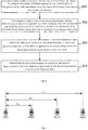
- FIG. 2 Take an equally spaced four-microphone array as shown in Fig. 2 as an example.
- FIG. 3 An application scenario of the equally spaced four-microphone array is shown in Fig. 3 .
- Four microphones constitute one equally spaced microphone array to inhibit noise signals from a lateral direction and maintain a user speech from the front.
- the full frequency band can be divided into a low-frequency sub-band, an intermediate-frequency sub-band and a high-frequency sub-band corresponding to three sub-bands from low to high frequency.
- the full frequency band can be divided into a low-frequency sub-band, an intermediate-frequency sub-band and a high-frequency sub-band corresponding to three sub-bands from low to high frequency.
- a spacing D 14 between the microphone MIC1 and the microphone MIC4 a spacing D 13 between the microphone MIC1 and the microphone MIC3; a spacing D 12 between the microphone MIC1 and the microphone MIC2; a spacing D 24 between the microphone MIC2 and the microphone MIC4; a spacing D 34 between the microphone MIC3 and the microphone MIC4; and a spacing D 23 between the microphone MIC2 and the microphone MIC3.
- the full frequency band can be divided into a low-frequency sub-band, an intermediate-frequency sub-band 1, an intermediate-frequency sub-band 2, an intermediate-frequency sub-band 3, an intermediate-frequency sub-band 4 and a high-frequency sub-band corresponding to six sub-bands from low to high frequency.
- S12 decomposing signals of each of the pairs of microphones with the different spacings into a corresponding one of the sub-bands, wherein the larger the spacing between each pair of microphones is, the lower the frequencies of the sub-band into which the signals of the pair of microphones are decomposed will be.
- the signals collected by the four microphones MIC1, MIC2, MIC3 and MIC4 are s 1 , s 2 , s 3 and s 4 , respectively.
- the signals s 1 and s 2 of the microphones MIC1 and MIC2 with the minimum spacing therebetween are decomposed by a sub-band decomposition unit into the high-frequency sub-band to obtain high-frequency component signals s 11 , s 21 .
- the signals s 1 and s 3 of the microphones MIC1 and MIC3 with the intermediate spacing therebetween are decomposed by the sub-band decomposition unit into the intermediate-frequency sub-band to obtain intermediate-frequency component signals s 12 , s 32 .
- the signals s 1 and s 4 of the microphones MIC1 and MIC4 with the maximum spacing therebetween are decomposed by the sub-band decomposition unit into the low-frequency sub-band to obtain low-frequency component signals s 13 , s 43 .
- a simple sub-band decomposition approach is to select a suitable low-pass filter, a suitable band-pass filter and a suitable high-pass filter, respectively, to filter the signals, respectively, to obtain respective low-frequency signals, intermediate-frequency signals and high-frequency signals;
- another sub-band decomposition approach which is more complex and accurate is to use an analysis filter set to decompose the signals into the low-frequency band, the intermediate-frequency band and the high-frequency band.
- the signal of any of the microphones is selected as a desired signal.
- the signal of the outermost microphone of the microphone array is preferably selected as the desired signal.
- the signal s 1 of the microphone MIC1 is selected as the desired signal and the signals of the other microphones are used as reference signals.
- the signals s 1 and s 2 of the microphones MIC1 and MIC2 with the minimum spacing therebetween correspond to the decomposed signals s 11 , s 21 in the high-frequency sub-band.
- These two signals s 11 , s 21 are passed through an adaptive filter H 1 so that a high-frequency noise signal, from the lateral direction, in the signal s 11 is filtered out while the high-frequency user speech from the front is maintained so as to obtain an output signal y 1 of the high-frequency sub-band.
- the signals s j and s 3 of the microphones MIC1 and MIC3 with the intermediate spacing therebetween correspond to the decomposed signals s 12 , s 32 in the intermediate-frequency sub-band.
- These two signals s 12 , s 32 are passed through an adaptive filter H 2 so that an intermediate-frequency noise signal, from the lateral direction, in the signal s 12 is filtered out while the intermediate-frequency user speech from the front is maintained so as to obtain an output signal y 2 of the intermediate-frequency sub-band.
- the signals s 1 and s 4 of the microphones MIC1 and MIC4 with the maximum spacing therebetween correspond to the decomposed signals s 13 , s 43 in the low-frequency sub-band.
- the adaptive filter H 1 takes the adaptive filter H 1 as an example.
- the signal s 21 as the reference signal is inputted into the adaptive filter H 1 to be filtered.
- the output signal of the adaptive filter H 1 is subtracted from the desired signal s 11 to obtain the signal y 1 .
- the signal y 1 is fed back to the adaptive filter to update a weight of the filter so that the output signal of the filter approximates s 11 and the signal y 1 has the minimum energy.
- the adaptive filter is adaptively updated continuously to make the signal y 1 have the minimum energy (i.e., make the noises have the minimum energy), so as to achieve the noise reduction effect in the high-frequency band.
- the adaptive filters H 2 and H 3 reduce noises in the intermediate-frequency band and the low-frequency band, respectively.
- S14 synthesizing the noise-reduced signals of each of the sub-bands to obtain a signal in which the noises have been reduced with the multi-microphone array in the full frequency band.
- the sub-band synthesis approach is selected depending on the sub-band decomposition approach adopted. Specifically, for the sub-band decomposition approach of selecting a suitable low-pass filter, a suitable band-pass filter and a suitable high-pass filter, respectively, to filter the signals, respectively, to obtain decomposed signals in the corresponding sub-bands, the full frequency band noise-reduced signal is obtained by using a sub-band synthesis approach of directly adding the noise-reduced signals of each of the sub-bands together; for the sub-band decomposition approach of using an analysis filter set to obtain decomposed signals in the corresponding sub-bands, the full frequency band noise-reduced signal is obtained by using a sub-band synthesis approach of using a corresponding synthesis filter set to synthesize the noise-reduced signals of each of the sub-bands.
- the method for eliminating noises with multi-microphone array divides a full frequency band into the same number of sub-bands as the number of different spacings between microphones of the multi-microphone array, decomposes signals of each of the pairs of microphones with the different spacings into a corresponding one of the sub-bands, then adaptively reduces the noises in the signals of each of the pairs of microphones with the different spacings in the corresponding sub-band to obtain noise-reduced signals for each of the sub-bands, and finally synthesizes the noise-reduced signals of each of the sub-bands to obtain a full frequency band noise-reduced signal.
- the method for eliminating noises with multi-microphone array further comprises acquiring a control parameter of an adaptive filter according to the amount of target signal components within a protection angle, and inputting the control parameter into the adaptive filter that adaptively reduces the noises in the corresponding sub-band.
- the aforesaid target signal components mainly refer to the components, within the protection angle, of a signal incidence angle of each of the pairs of microphones.
- the adaptive filter In the process of the aforesaid step S13 of adaptively reducing the noises in the decomposed signals of each of the pairs of microphones with the different spacings in the corresponding sub-band, if the adaptive filter is still updated freely when a user speech is received by the microphone array, the adaptive filter will also eliminate the speech as the noises. Therefore, the updating of the adaptive filter must be controlled. When there exist only noises, the adaptive filter is allowed to be updated freely to effectively inhibit the noises; and when there exists a speech, the updating of the adaptive filter is stopped to protect the speech from being inhibited.
- the adaptive filter may be selected from a time-domain filter, a frequency-domain filter and a sub-band filter. For a frequency adaptive filter or a sub-band adaptive filter, it is necessary to transform signals of the full frequency band into a frequency domain or sub-bands, respectively, before performing adaptive filtering and then to transform the filtered signals back into time-domain signals.
- the embodiment of the present invention provides an approach of acquiring a control parameter of an adaptive filter according to the amount of target signal components within a protection angle, the approach comprising
- the four microphone signals s 1 , s 2 , s 3 and s 4 are transformed into the frequency domain through Discrete Fourier Transform (DFT).
- DFT Discrete Fourier Transform
- phase differences of signals of the three pairs of microphones i.e., the microphones MIC1 and MIC2, the microphones MIC1 and MIC3, and the microphones MIC1 and MIC4
- a relative delay of the signals of each of the pairs of microphones is calculated according to the phase differences.
- a signal incidence angle of each of the pairs of microphones can be calculated according to the relative delay of the signals of the pair of microphones and the spacing between the pair of microphones, and three signal incidence angles are calculated for the three pairs of microphones.
- statistics is made on the amount of components, within the protection angle, of the three signal incidence angles so as to obtain the control parameter of the adaptive filter.
- the updating of the adaptive filter can be controlled by means of a signal incidence angle. If the signal incidence angle is within the protection angle, then it is regarded as a forward user speech and the adaptive filter shall stop updating; and if the signal incidence angle is outside the protection angle, then it is regarded as a lateral noise and the adaptive filter can be updated freely.
- the adaptive filters that adaptively reduce the noises in different sub-bands may have the same or different control parameters.
- statistics may be made on the amount of components, within the protection angle, of the signal incidence angle of each of the pairs of microphones in the full frequency band, and a unified control parameter ⁇ (0 ⁇ 1) of the adaptive filter in the full frequency band can be obtained through conversion according to the statistic result.
- statistics may also be made on the amount of components, within the protection angle, of the signal incidence angle of each of the pairs of microphones in each of the sub-bands, respectively, and a control parameter ⁇ i (0 ⁇ i ⁇ 1) of the adaptive filter of the i th sub-band can be obtained through conversion according to the statistic result.
- ⁇ i (0 ⁇ i ⁇ 1) of the adaptive filter of the i th sub-band
- the aforesaid target signal components mainly refer to the components, within the protection angle, of the signal incidence angle of each of the pairs of microphones.
- the preferred embodiment of the present invention can not only effectively inhibit the noises in the broad frequency band but also meanwhile ensure a high speech quality to increase the signal-to-noise ratio of the full frequency band.
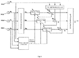
- a device for eliminating noises with multi-microphone array comprises a sub-band decomposition unit 101, being configured to, according to the number of different spacings between each of pairs of microphones of the multi-microphone array, divide a full frequency band into the same number of sub-bands, and to decompose signals of each of the pairs of microphones with the different spacings into a corresponding one of the sub-bands, wherein the larger the spacing between each pair of microphones is, the lower the frequencies of the sub-band into which the signals of the pair of microphones are decomposed will be; an adaptive filter 102, being configured to adaptively reduce the noises in the decomposed signals of each of the pairs of microphones with the different spacings in the corresponding sub-band to obtain noise-reduced signals for each of the sub-bands; and a sub-band synthesizing unit 103, being configured to synthesize the noise-reduced signals of each of the sub-bands to obtain a
- the sub-band decomposition unit 101 may select a suitable low-pass filter, a suitable band-pass filter and a suitable high-pass filter to filter the signals of each of the pairs of microphones with the different spacings, respectively, to obtain signals in the corresponding sub-band; or use an analysis filter set to decompose the signals of each of the pairs of microphones with the different spacings into the corresponding sub-band.
- the sub-band synthesizing unit 103 obtains the full frequency band noise-reduced signal by using a sub-band synthesis approach of directly adding the noise-reduced signals of each of the sub-bands together.
- the sub-band synthesizing unit 103 obtains the full frequency band noise-reduced signal by using a sub-band synthesis approach of using a corresponding synthesis filter set to synthesize the noise-reduced signals of each of the sub-bands.
- the device for eliminating noises with multi-microphone array further comprises a noise-reduction control unit 104, being configured to acquire a control parameter of the adaptive filter according to the amount of target signal components within a protection angle, and input the control parameter into the adaptive filter 102 that adaptively reduces the noises in the corresponding sub-band.
- the aforesaid target signal components mainly refer to the components, within the protection angle, of the signal incidence angle of each of the pairs of microphones.
- the noise-reduction control unit 104 may comprise a DFT module 1041, being configured to transform the signal of each of the microphones of the multi-microphone array into a frequency domain through Discrete Fourier Transform (DFT); a delay calculation module 1042, being configured to calculate a relative delay of the signals of each of the pairs of microphones with the different spacings in the frequency domain; a direction calculation module 1043, being configured to calculate a signal incidence angle of each of the pairs of microphones according to the relative delay and the corresponding one of the different spacings; and a control parameter acquiring module 1044, being configured to make statistics on the amount of signal components whose incidence angle is within the protection angle, for each of the pairs of microphones and obtain the control parameter of the adaptive filter through conversion according to the statistic result.
- DFT Discrete Fourier Transform
- control parameter acquiring module 1044 may be a full frequency band control parameter acquiring module, which is configured to make statistics on the amount of signal components whose incidence angle is within the protection angle, for each of the pairs of microphones in the full frequency band and obtain a unified control parameter ⁇ (0 ⁇ 1) of the adaptive filter in the full frequency band through conversion according to the statistic result.
- control parameter acquiring module 1044 may be a sub-band control parameter acquiring module, which is configured to make statistics on the amount of signal components whose incidence angle is within the protection angle, for each of the pairs of microphones in each of the sub-bands, respectively, and obtain a control parameter ⁇ i (0 ⁇ i ⁇ 1) of the adaptive filter of the i th sub-band through conversion according to the statistic result.
- each of the functional units or modules of the device can be readily known with reference to the method according to the previous embodiment of the present invention.
- the device for eliminating noises with multi-microphone array may be implemented by hardware logic or software; each of the functional units or modules of the device may be integrated together or be deployed separately; and a plurality of functional units or modules may be combined into a single unit or be further divided into a plurality of sub-units.
- the device for eliminating noises with multi-microphone array divides a full frequency band into the same number of sub-bands as the number of different spacings between microphones of the multi-microphone array, decomposes signals of each of the pairs of microphones with the different spacings into a corresponding one of the sub-bands through the sub-band decomposition unit 101, then adaptively reduces the noises in the signals of each of the pairs of microphones with the different spacings in the corresponding sub-band through the adaptive filter 102 to obtain noise-reduced signals for each of the sub-bands, and finally synthesizes the noise-reduced signals of each of the sub-bands through the sub-band synthesizing unit 103 to obtain a full frequency band noise-reduced signal.
- the noise-reduction control unit 104 acquires a control parameter of an adaptive filter according to the amount of target signal components within a protection angle and inputs the control parameter into the adaptive filter, which adaptively reduces the noises in the corresponding sub-band, to control an updating speed of the adaptive filter.
- This can not only effectively inhibit the noises in the broad frequency band but also meanwhile ensure a high speech quality to increase the signal-to-noise ratio of the full frequency band.
- an embodiment of the present invention further provides a system for eliminating noises with multi-microphone array, the system comprising a multi-microphone array, the multi-microphone array consisting of three or more microphones which have equal or different spacings therebetween; and the device for eliminating noises with multi-microphone array according to the aforesaid embodiment of the present invention, being configured to perform noise reduction processing on signals collected by the multi-microphone array.
- the technical solution according to the aforesaid embodiment of the present invention is suitable for use in an equally spaced or unequally spaced multi-microphone array consisting of three or more microphones, wherein the microphones are not limited in direction and may be unidirectional or omnidirectional.
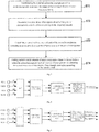
- the processing procedure of the present invention is as follows.
- Step 1 firstly passing the four signals through the noise-reduction control unit to estimate the incidence angles of the signals in the frequency domain and accordingly calculate the control parameter ⁇ to control updating of the adaptive filter.
- the m th frame signal is d i ( m , n ), where 0 ⁇ n ⁇ N and 0 ⁇ m.
- the window function may be selected from the Hamming window, the Hanning window and the like.
- Step 2 decomposing the signals s 1 , s 2 , s 3 and s 4 into high-frequency signals s 11 and s 21 , intermediate-frequency signals s 12 and s 32 , and low-frequency signals s 13 and s 43 through the sub-band decomposition unit.
- Step 3 passing the high-frequency signals s 11 and s 21 through a time-domain adaptive filter H 1 , the updating of which is controlled by the control parameter ⁇ , to obtain a noise-reduced high-frequency component y 1 ; passing the intermediate-frequency signals s 12 and s 32 through a time-domain adaptive filter H 2 , the updating of which is controlled by the control parameter ⁇ , to obtain a noise-reduced intermediate-frequency component y 2 ; and passing the low-frequency signals s 13 and s 43 through a time-domain adaptive filter H 3 , the updating of which is controlled by the control parameter ⁇ , to obtain a noise-reduced low-frequency component y 3 .
- P 64.
- the updating speed ⁇ of the adaptive filter H j is controlled by the parameter ⁇ .
- ⁇ 0.3 * ⁇ .
- ⁇ 0.3 and the adaptive filter converges rapidly until the signal y j (n) has the minimum energy so that the noises are eliminated.
- ⁇ 0 and the adaptive filter stops updating so that the speech components will not be offset and will be maintained in the output signal y j (n).
- the updating speed of the adaptive filter is controlled by the amount of the speech components and the amount of the noise components to ensure that the noises are eliminated while the speech components are maintained.
- Step 4 synthesizing the high-frequency signal y 1 , the intermediate-frequency signal y 2 and the low-frequency signal y 3 by the sub-band synthesizing unit into a full frequency band noise-reduced signal y.
- the protection range of the protection angle selected in this embodiment is between -45° and 45°; however, in practice, the protection range may be adjusted according to the actual location and requirements of the user.
- the number of the microphones is not limited to four, either, but may be any other number equal to or larger than three; and the spacings between adjacent ones of the microphones are not necessarily identical. More microphones and more spacings of microphones can be used to decompose the signals into more and narrower sub-bands so that more accurate adaptive noise reduction processing can be performed to achieve a better noise reduction effect.
- the time-domain adaptive filter can be used to reduce the noises during the adaptive noise reduction processing in each of the sub-bands in the embodiments of the present invention; however, the application of the present invention is not limited to the time-domain adaptive filter, and the frequency-domain or sub-band adaptive filter may also be used to reduce the noises.
- the present invention may use a low-pass filter, a band-pass filter and a high-pass filter for sub-band decomposition and add the sub-band components together for sub-band synthesis; however, the present invention may also use more accurate sub-band decomposition and synthesis approaches (e.g., in a manner of using an analysis filter set and a synthesis filter set to reduce signal distortion caused by sub-band decomposition and synthesis).
- the method, the device and the system for eliminating noises with multi-microphone array can be used in scenarios of hands-free video calls.
- the present invention can increase the signal-to-noise ratio of the full frequency band to make the hands-free calls clearer and smoother.
Landscapes
- Engineering & Computer Science (AREA)
- Physics & Mathematics (AREA)
- Acoustics & Sound (AREA)
- Signal Processing (AREA)
- Health & Medical Sciences (AREA)
- Multimedia (AREA)
- Otolaryngology (AREA)
- General Health & Medical Sciences (AREA)
- Computational Linguistics (AREA)
- Quality & Reliability (AREA)
- Audiology, Speech & Language Pathology (AREA)
- Human Computer Interaction (AREA)
- Circuit For Audible Band Transducer (AREA)
- Obtaining Desirable Characteristics In Audible-Bandwidth Transducers (AREA)
- Soundproofing, Sound Blocking, And Sound Damping (AREA)
Applications Claiming Priority (2)
| Application Number | Priority Date | Filing Date | Title |
|---|---|---|---|
| CN201110259355.9A CN102306496B (zh) | 2011-09-05 | 2011-09-05 | 一种多麦克风阵列噪声消除方法、装置及系统 |
| PCT/CN2012/073712 WO2013033991A1 (zh) | 2011-09-05 | 2012-04-10 | 一种多麦克风阵列噪声消除方法、装置及系统 |
Publications (3)
| Publication Number | Publication Date |
|---|---|
| EP2608197A1 EP2608197A1 (en) | 2013-06-26 |
| EP2608197A4 EP2608197A4 (en) | 2015-04-08 |
| EP2608197B1 true EP2608197B1 (en) | 2019-01-09 |
Family
ID=45380344
Family Applications (1)
| Application Number | Title | Priority Date | Filing Date |
|---|---|---|---|
| EP12830760.0A Active EP2608197B1 (en) | 2011-09-05 | 2012-04-10 | Method, device, and system for noise reduction in multi-microphone array |
Country Status (7)
| Country | Link |
|---|---|
| US (1) | US9129587B2 (enExample) |
| EP (1) | EP2608197B1 (enExample) |
| JP (2) | JP2013542677A (enExample) |
| KR (1) | KR101519768B1 (enExample) |
| CN (1) | CN102306496B (enExample) |
| DK (1) | DK2608197T3 (enExample) |
| WO (1) | WO2013033991A1 (enExample) |
Families Citing this family (41)
| Publication number | Priority date | Publication date | Assignee | Title |
|---|---|---|---|---|
| US9247346B2 (en) | 2007-12-07 | 2016-01-26 | Northern Illinois Research Foundation | Apparatus, system and method for noise cancellation and communication for incubators and related devices |
| CN102306496B (zh) * | 2011-09-05 | 2014-07-09 | 歌尔声学股份有限公司 | 一种多麦克风阵列噪声消除方法、装置及系统 |
| EP2997574A1 (en) * | 2013-05-13 | 2016-03-23 | Thomson Licensing | Method, apparatus and system for isolating microphone audio |
| US9591404B1 (en) * | 2013-09-27 | 2017-03-07 | Amazon Technologies, Inc. | Beamformer design using constrained convex optimization in three-dimensional space |
| CN104751854A (zh) * | 2013-12-26 | 2015-07-01 | 联芯科技有限公司 | 一种宽带声学回声消除方法及系统 |
| JP6160519B2 (ja) * | 2014-03-07 | 2017-07-12 | 株式会社Jvcケンウッド | 雑音低減装置 |
| WO2015137146A1 (ja) * | 2014-03-12 | 2015-09-17 | ソニー株式会社 | 音場収音装置および方法、音場再生装置および方法、並びにプログラム |
| KR102188101B1 (ko) | 2014-03-14 | 2020-12-07 | 삼성전자주식회사 | 오디오 처리 방법 및 그 전자 장치 |
| US10149047B2 (en) * | 2014-06-18 | 2018-12-04 | Cirrus Logic Inc. | Multi-aural MMSE analysis techniques for clarifying audio signals |
| US9721584B2 (en) * | 2014-07-14 | 2017-08-01 | Intel IP Corporation | Wind noise reduction for audio reception |
| CN104602163B (zh) | 2014-12-31 | 2017-12-01 | 歌尔股份有限公司 | 主动降噪耳机及应用于该耳机的降噪控制方法和系统 |
| GB201518240D0 (en) * | 2015-10-15 | 2015-12-02 | Rolls Royce Plc | A method of performing real time decomposition of a signal into components |
| CN105280195B (zh) * | 2015-11-04 | 2018-12-28 | 腾讯科技(深圳)有限公司 | 语音信号的处理方法及装置 |
| CN105390142B (zh) * | 2015-12-17 | 2019-04-05 | 广州大学 | 一种数字助听器语音噪声消除方法 |
| US10257620B2 (en) * | 2016-07-01 | 2019-04-09 | Sonova Ag | Method for detecting tonal signals, a method for operating a hearing device based on detecting tonal signals and a hearing device with a feedback canceller using a tonal signal detector |
| CN106448693B (zh) * | 2016-09-05 | 2019-11-29 | 华为技术有限公司 | 一种语音信号处理方法及装置 |
| CN106710601B (zh) * | 2016-11-23 | 2020-10-13 | 合肥美的智能科技有限公司 | 一种语音信号降噪拾音处理方法和装置及冰箱 |
| US9947337B1 (en) * | 2017-03-21 | 2018-04-17 | Omnivision Technologies, Inc. | Echo cancellation system and method with reduced residual echo |
| CN106910492A (zh) * | 2017-04-01 | 2017-06-30 | 广州日滨科技发展有限公司 | 一种电梯轿厢的噪声主动控制方法和装置 |
| CN107748354B (zh) * | 2017-08-08 | 2021-11-30 | 中国电子科技集团公司第三十八研究所 | 基于分析与综合的宽带数字波束形成装置 |
| CN107749305B (zh) * | 2017-09-29 | 2021-08-24 | 百度在线网络技术(北京)有限公司 | 语音处理方法及其装置 |
| CN107749296A (zh) * | 2017-10-12 | 2018-03-02 | 深圳市沃特沃德股份有限公司 | 语音翻译方法和装置 |
| US10354635B2 (en) | 2017-11-01 | 2019-07-16 | Bose Corporation | Adaptive nullforming for selective audio pick-up |
| US11430421B2 (en) | 2017-11-01 | 2022-08-30 | Bose Corporation | Adaptive null forming and echo cancellation for selective audio pick-up |
| CN108335697A (zh) * | 2018-01-29 | 2018-07-27 | 北京百度网讯科技有限公司 | 会议记录方法、装置、设备及计算机可读介质 |
| CN108696797A (zh) * | 2018-05-17 | 2018-10-23 | 四川湖山电器股份有限公司 | 一种音频电信号进行分频与合成的方法 |
| US10615887B1 (en) * | 2018-09-24 | 2020-04-07 | Seagate Technology Llc | Mitigation of noise generated by random excitation of asymmetric oscillation modes |
| CN110033776A (zh) * | 2019-03-08 | 2019-07-19 | 佛山市云米电器科技有限公司 | 一种应用于屏幕设备的虚拟形象交互系统与方法 |
| WO2020241050A1 (ja) * | 2019-05-28 | 2020-12-03 | ソニー株式会社 | 音声処理装置、音声処理方法およびプログラム |
| TWI731391B (zh) * | 2019-08-15 | 2021-06-21 | 緯創資通股份有限公司 | 麥克風裝置、電子裝置及其音訊信號處理方法 |
| DK3812576T3 (da) * | 2019-10-23 | 2023-07-17 | Siemens Gamesa Renewable Energy As | Rotorblad med støjreduktionsmidler |
| CN110767247B (zh) * | 2019-10-29 | 2021-02-19 | 支付宝(杭州)信息技术有限公司 | 语音信号处理方法、声音采集装置和电子设备 |
| JP7486145B2 (ja) * | 2019-11-21 | 2024-05-17 | パナソニックIpマネジメント株式会社 | 音響クロストーク抑圧装置および音響クロストーク抑圧方法 |
| CN112019977A (zh) * | 2020-09-04 | 2020-12-01 | 广州郝舜科技有限公司 | 一种大数据采集用音频采集装置 |
| CN112562730A (zh) * | 2020-11-24 | 2021-03-26 | 北京华捷艾米科技有限公司 | 一种声源分析方法及系统 |
| US11290814B1 (en) | 2020-12-15 | 2022-03-29 | Valeo North America, Inc. | Method, apparatus, and computer-readable storage medium for modulating an audio output of a microphone array |
| CN113163281B (zh) * | 2021-02-23 | 2023-06-02 | 深圳壹秘科技有限公司 | 麦克风及麦克风的降噪系统 |
| CN116918350A (zh) * | 2021-04-25 | 2023-10-20 | 深圳市韶音科技有限公司 | 声学装置 |
| CN113329288B (zh) * | 2021-04-29 | 2022-07-19 | 开放智能技术(南京)有限公司 | 一种基于陷波技术的蓝牙耳机降噪方法 |
| CN115396783B (zh) * | 2022-08-24 | 2024-09-27 | 音曼(北京)科技有限公司 | 基于麦克风阵列的自适应波束宽度的音频采集方法及装置 |
| CN116320851A (zh) * | 2023-01-17 | 2023-06-23 | 泰凌微电子(上海)股份有限公司 | 麦克风阵列降噪方法、装置、系统、电子设备及存储介质 |
Family Cites Families (18)
| Publication number | Priority date | Publication date | Assignee | Title |
|---|---|---|---|---|
| JP3154151B2 (ja) * | 1993-03-10 | 2001-04-09 | ソニー株式会社 | マイクロホン装置 |
| JP3131716B2 (ja) * | 1993-05-13 | 2001-02-05 | 長野日本無線株式会社 | 音声検出装置 |
| JP2000069583A (ja) * | 1998-08-25 | 2000-03-03 | Fujitsu Ten Ltd | 音声入力装置 |
| JP3732041B2 (ja) * | 1999-06-11 | 2006-01-05 | ティーオーエー株式会社 | マイクロホン装置 |
| WO2003003349A1 (en) * | 2001-06-28 | 2003-01-09 | Oticon A/S | Method for noise reduction and microphone array for performing noise reduction |
| AUPR647501A0 (en) * | 2001-07-19 | 2001-08-09 | Vast Audio Pty Ltd | Recording a three dimensional auditory scene and reproducing it for the individual listener |
| JP2003333683A (ja) * | 2002-05-16 | 2003-11-21 | Tokai Rika Co Ltd | ノイズ抑圧方法及びマイクロフォン装置 |
| JP4156545B2 (ja) * | 2004-03-12 | 2008-09-24 | 株式会社国際電気通信基礎技術研究所 | マイクロホンアレー |
| JP4747949B2 (ja) * | 2006-05-25 | 2011-08-17 | ヤマハ株式会社 | 音声会議装置 |
| KR100856246B1 (ko) * | 2007-02-07 | 2008-09-03 | 삼성전자주식회사 | 실제 잡음 환경의 특성을 반영한 빔포밍 장치 및 방법 |
| EP2063419B1 (en) * | 2007-11-21 | 2012-04-18 | Nuance Communications, Inc. | Speaker localization |
| CN101447190A (zh) * | 2008-06-25 | 2009-06-03 | 北京大学深圳研究生院 | 基于嵌套子阵列的后置滤波与谱减法联合语音增强方法 |
| GB0906269D0 (en) * | 2009-04-09 | 2009-05-20 | Ntnu Technology Transfer As | Optimal modal beamformer for sensor arrays |
| CN102111697B (zh) * | 2009-12-28 | 2015-03-25 | 歌尔声学股份有限公司 | 一种麦克风阵列降噪控制方法及装置 |
| US8787114B1 (en) * | 2010-09-13 | 2014-07-22 | The Boeing Company | Audio surveillance system |
| KR101782050B1 (ko) * | 2010-09-17 | 2017-09-28 | 삼성전자주식회사 | 비등간격으로 배치된 마이크로폰을 이용한 음질 향상 장치 및 방법 |
| US8861756B2 (en) * | 2010-09-24 | 2014-10-14 | LI Creative Technologies, Inc. | Microphone array system |
| CN102306496B (zh) * | 2011-09-05 | 2014-07-09 | 歌尔声学股份有限公司 | 一种多麦克风阵列噪声消除方法、装置及系统 |
-
2011
- 2011-09-05 CN CN201110259355.9A patent/CN102306496B/zh active Active
-
2012
- 2012-04-10 KR KR1020137006867A patent/KR101519768B1/ko active Active
- 2012-04-10 DK DK12830760.0T patent/DK2608197T3/en active
- 2012-04-10 JP JP2013532045A patent/JP2013542677A/ja active Pending
- 2012-04-10 US US13/814,559 patent/US9129587B2/en active Active
- 2012-04-10 WO PCT/CN2012/073712 patent/WO2013033991A1/zh not_active Ceased
- 2012-04-10 EP EP12830760.0A patent/EP2608197B1/en active Active
-
2016
- 2016-06-09 JP JP2016115637A patent/JP6142044B2/ja active Active
Non-Patent Citations (1)
| Title |
|---|
| None * |
Also Published As
| Publication number | Publication date |
|---|---|
| CN102306496A (zh) | 2012-01-04 |
| KR101519768B1 (ko) | 2015-05-12 |
| US20130142349A1 (en) | 2013-06-06 |
| EP2608197A4 (en) | 2015-04-08 |
| DK2608197T3 (en) | 2019-04-08 |
| JP6142044B2 (ja) | 2017-06-07 |
| CN102306496B (zh) | 2014-07-09 |
| JP2013542677A (ja) | 2013-11-21 |
| WO2013033991A1 (zh) | 2013-03-14 |
| US9129587B2 (en) | 2015-09-08 |
| JP2016192781A (ja) | 2016-11-10 |
| KR20130063529A (ko) | 2013-06-14 |
| EP2608197A1 (en) | 2013-06-26 |
Similar Documents
| Publication | Publication Date | Title |
|---|---|---|
| EP2608197B1 (en) | Method, device, and system for noise reduction in multi-microphone array | |
| CN105590631B (zh) | 信号处理的方法及装置 | |
| US8942976B2 (en) | Method and device for noise reduction control using microphone array | |
| EP2393463B1 (en) | Multiple microphone based directional sound filter | |
| EP2932731B1 (en) | Spatial interference suppression using dual- microphone arrays | |
| US11373667B2 (en) | Real-time single-channel speech enhancement in noisy and time-varying environments | |
| US9232309B2 (en) | Microphone array processing system | |
| CN202307119U (zh) | 一种多麦克风阵列噪声消除装置及系统 | |
| CN102347028A (zh) | 双麦克风语音增强装置及方法 | |
| EP3275208B1 (en) | Sub-band mixing of multiple microphones | |
| CN107993670A (zh) | 基于统计模型的麦克风阵列语音增强方法 | |
| CN101976565A (zh) | 基于双麦克风语音增强装置及方法 | |
| CN108447500B (zh) | 语音增强的方法与装置 | |
| TW201142829A (en) | Adaptive noise reduction using level cues | |
| US8615392B1 (en) | Systems and methods for producing an acoustic field having a target spatial pattern | |
| EP3692529B1 (en) | An apparatus and a method for signal enhancement | |
| CN107409255A (zh) | 子带信号的自适应混合 | |
| CN108806712B (zh) | 减少频域处理量的方法与装置 | |
| Kumatani et al. | Microphone array post-filter based on spatially-correlated noise measurements for distant speech recognition | |
| WO2009096958A1 (en) | Noise suppressor system and method | |
| Yousefian et al. | A coherence-based algorithm for noise reduction in dual-microphone applications | |
| CN108717855B (zh) | 噪音处理方法与装置 | |
| CN108702558B (zh) | 用于估计到达方向的方法和装置及电子设备 | |
| CN112017684A (zh) | 一种基于麦克风阵列的密闭空间混响消除方法 | |
| US12401942B1 (en) | Group beam selection and beam merging |
Legal Events
| Date | Code | Title | Description |
|---|---|---|---|
| PUAI | Public reference made under article 153(3) epc to a published international application that has entered the european phase |
Free format text: ORIGINAL CODE: 0009012 |
|
| 17P | Request for examination filed |
Effective date: 20130318 |
|
| AK | Designated contracting states |
Kind code of ref document: A1 Designated state(s): AL AT BE BG CH CY CZ DE DK EE ES FI FR GB GR HR HU IE IS IT LI LT LU LV MC MK MT NL NO PL PT RO RS SE SI SK SM TR |
|
| AX | Request for extension of the european patent |
Extension state: BA ME |
|
| RIN1 | Information on inventor provided before grant (corrected) |
Inventor name: LI, BO Inventor name: LIU, SONG |
|
| RA4 | Supplementary search report drawn up and despatched (corrected) |
Effective date: 20150310 |
|
| RIC1 | Information provided on ipc code assigned before grant |
Ipc: G10L 21/0216 20130101ALI20150304BHEP Ipc: G10L 21/0208 20130101AFI20150304BHEP |
|
| REG | Reference to a national code |
Ref country code: DE Ref legal event code: R079 Ref document number: 602012055818 Country of ref document: DE Free format text: PREVIOUS MAIN CLASS: G10L0021020000 Ipc: G10L0021020800 |
|
| RIC1 | Information provided on ipc code assigned before grant |
Ipc: H04R 3/00 20060101ALI20180731BHEP Ipc: G10L 21/0216 20130101ALI20180731BHEP Ipc: G10L 21/0208 20130101AFI20180731BHEP |
|
| GRAP | Despatch of communication of intention to grant a patent |
Free format text: ORIGINAL CODE: EPIDOSNIGR1 |
|
| STAA | Information on the status of an ep patent application or granted ep patent |
Free format text: STATUS: GRANT OF PATENT IS INTENDED |
|
| INTG | Intention to grant announced |
Effective date: 20180913 |
|
| GRAS | Grant fee paid |
Free format text: ORIGINAL CODE: EPIDOSNIGR3 |
|
| GRAA | (expected) grant |
Free format text: ORIGINAL CODE: 0009210 |
|
| STAA | Information on the status of an ep patent application or granted ep patent |
Free format text: STATUS: THE PATENT HAS BEEN GRANTED |
|
| AK | Designated contracting states |
Kind code of ref document: B1 Designated state(s): AL AT BE BG CH CY CZ DE DK EE ES FI FR GB GR HR HU IE IS IT LI LT LU LV MC MK MT NL NO PL PT RO RS SE SI SK SM TR |
|
| AX | Request for extension of the european patent |
Extension state: BA ME |
|
| REG | Reference to a national code |
Ref country code: GB Ref legal event code: FG4D |
|
| REG | Reference to a national code |
Ref country code: CH Ref legal event code: EP Ref country code: AT Ref legal event code: REF Ref document number: 1088305 Country of ref document: AT Kind code of ref document: T Effective date: 20190115 |
|
| REG | Reference to a national code |
Ref country code: DE Ref legal event code: R096 Ref document number: 602012055818 Country of ref document: DE |
|
| REG | Reference to a national code |
Ref country code: IE Ref legal event code: FG4D |
|
| REG | Reference to a national code |
Ref country code: DK Ref legal event code: T3 Effective date: 20190404 |
|
| REG | Reference to a national code |
Ref country code: NL Ref legal event code: MP Effective date: 20190109 |
|
| REG | Reference to a national code |
Ref country code: LT Ref legal event code: MG4D |
|
| PG25 | Lapsed in a contracting state [announced via postgrant information from national office to epo] |
Ref country code: NL Free format text: LAPSE BECAUSE OF FAILURE TO SUBMIT A TRANSLATION OF THE DESCRIPTION OR TO PAY THE FEE WITHIN THE PRESCRIBED TIME-LIMIT Effective date: 20190109 |
|
| REG | Reference to a national code |
Ref country code: AT Ref legal event code: MK05 Ref document number: 1088305 Country of ref document: AT Kind code of ref document: T Effective date: 20190109 |
|
| PG25 | Lapsed in a contracting state [announced via postgrant information from national office to epo] |
Ref country code: FI Free format text: LAPSE BECAUSE OF FAILURE TO SUBMIT A TRANSLATION OF THE DESCRIPTION OR TO PAY THE FEE WITHIN THE PRESCRIBED TIME-LIMIT Effective date: 20190109 Ref country code: NO Free format text: LAPSE BECAUSE OF FAILURE TO SUBMIT A TRANSLATION OF THE DESCRIPTION OR TO PAY THE FEE WITHIN THE PRESCRIBED TIME-LIMIT Effective date: 20190409 Ref country code: PT Free format text: LAPSE BECAUSE OF FAILURE TO SUBMIT A TRANSLATION OF THE DESCRIPTION OR TO PAY THE FEE WITHIN THE PRESCRIBED TIME-LIMIT Effective date: 20190509 Ref country code: ES Free format text: LAPSE BECAUSE OF FAILURE TO SUBMIT A TRANSLATION OF THE DESCRIPTION OR TO PAY THE FEE WITHIN THE PRESCRIBED TIME-LIMIT Effective date: 20190109 Ref country code: PL Free format text: LAPSE BECAUSE OF FAILURE TO SUBMIT A TRANSLATION OF THE DESCRIPTION OR TO PAY THE FEE WITHIN THE PRESCRIBED TIME-LIMIT Effective date: 20190109 Ref country code: SE Free format text: LAPSE BECAUSE OF FAILURE TO SUBMIT A TRANSLATION OF THE DESCRIPTION OR TO PAY THE FEE WITHIN THE PRESCRIBED TIME-LIMIT Effective date: 20190109 Ref country code: LT Free format text: LAPSE BECAUSE OF FAILURE TO SUBMIT A TRANSLATION OF THE DESCRIPTION OR TO PAY THE FEE WITHIN THE PRESCRIBED TIME-LIMIT Effective date: 20190109 |
|
| PG25 | Lapsed in a contracting state [announced via postgrant information from national office to epo] |
Ref country code: HR Free format text: LAPSE BECAUSE OF FAILURE TO SUBMIT A TRANSLATION OF THE DESCRIPTION OR TO PAY THE FEE WITHIN THE PRESCRIBED TIME-LIMIT Effective date: 20190109 Ref country code: RS Free format text: LAPSE BECAUSE OF FAILURE TO SUBMIT A TRANSLATION OF THE DESCRIPTION OR TO PAY THE FEE WITHIN THE PRESCRIBED TIME-LIMIT Effective date: 20190109 Ref country code: BG Free format text: LAPSE BECAUSE OF FAILURE TO SUBMIT A TRANSLATION OF THE DESCRIPTION OR TO PAY THE FEE WITHIN THE PRESCRIBED TIME-LIMIT Effective date: 20190409 Ref country code: GR Free format text: LAPSE BECAUSE OF FAILURE TO SUBMIT A TRANSLATION OF THE DESCRIPTION OR TO PAY THE FEE WITHIN THE PRESCRIBED TIME-LIMIT Effective date: 20190410 Ref country code: IS Free format text: LAPSE BECAUSE OF FAILURE TO SUBMIT A TRANSLATION OF THE DESCRIPTION OR TO PAY THE FEE WITHIN THE PRESCRIBED TIME-LIMIT Effective date: 20190509 Ref country code: LV Free format text: LAPSE BECAUSE OF FAILURE TO SUBMIT A TRANSLATION OF THE DESCRIPTION OR TO PAY THE FEE WITHIN THE PRESCRIBED TIME-LIMIT Effective date: 20190109 |
|
| REG | Reference to a national code |
Ref country code: DE Ref legal event code: R097 Ref document number: 602012055818 Country of ref document: DE |
|
| PG25 | Lapsed in a contracting state [announced via postgrant information from national office to epo] |
Ref country code: EE Free format text: LAPSE BECAUSE OF FAILURE TO SUBMIT A TRANSLATION OF THE DESCRIPTION OR TO PAY THE FEE WITHIN THE PRESCRIBED TIME-LIMIT Effective date: 20190109 Ref country code: IT Free format text: LAPSE BECAUSE OF FAILURE TO SUBMIT A TRANSLATION OF THE DESCRIPTION OR TO PAY THE FEE WITHIN THE PRESCRIBED TIME-LIMIT Effective date: 20190109 Ref country code: AT Free format text: LAPSE BECAUSE OF FAILURE TO SUBMIT A TRANSLATION OF THE DESCRIPTION OR TO PAY THE FEE WITHIN THE PRESCRIBED TIME-LIMIT Effective date: 20190109 Ref country code: SK Free format text: LAPSE BECAUSE OF FAILURE TO SUBMIT A TRANSLATION OF THE DESCRIPTION OR TO PAY THE FEE WITHIN THE PRESCRIBED TIME-LIMIT Effective date: 20190109 Ref country code: AL Free format text: LAPSE BECAUSE OF FAILURE TO SUBMIT A TRANSLATION OF THE DESCRIPTION OR TO PAY THE FEE WITHIN THE PRESCRIBED TIME-LIMIT Effective date: 20190109 Ref country code: RO Free format text: LAPSE BECAUSE OF FAILURE TO SUBMIT A TRANSLATION OF THE DESCRIPTION OR TO PAY THE FEE WITHIN THE PRESCRIBED TIME-LIMIT Effective date: 20190109 Ref country code: CZ Free format text: LAPSE BECAUSE OF FAILURE TO SUBMIT A TRANSLATION OF THE DESCRIPTION OR TO PAY THE FEE WITHIN THE PRESCRIBED TIME-LIMIT Effective date: 20190109 |
|
| PLBE | No opposition filed within time limit |
Free format text: ORIGINAL CODE: 0009261 |
|
| STAA | Information on the status of an ep patent application or granted ep patent |
Free format text: STATUS: NO OPPOSITION FILED WITHIN TIME LIMIT |
|
| PG25 | Lapsed in a contracting state [announced via postgrant information from national office to epo] |
Ref country code: SM Free format text: LAPSE BECAUSE OF FAILURE TO SUBMIT A TRANSLATION OF THE DESCRIPTION OR TO PAY THE FEE WITHIN THE PRESCRIBED TIME-LIMIT Effective date: 20190109 |
|
| REG | Reference to a national code |
Ref country code: CH Ref legal event code: PL |
|
| 26N | No opposition filed |
Effective date: 20191010 |
|
| REG | Reference to a national code |
Ref country code: BE Ref legal event code: MM Effective date: 20190430 |
|
| PG25 | Lapsed in a contracting state [announced via postgrant information from national office to epo] |
Ref country code: LU Free format text: LAPSE BECAUSE OF NON-PAYMENT OF DUE FEES Effective date: 20190410 Ref country code: MC Free format text: LAPSE BECAUSE OF FAILURE TO SUBMIT A TRANSLATION OF THE DESCRIPTION OR TO PAY THE FEE WITHIN THE PRESCRIBED TIME-LIMIT Effective date: 20190109 |
|
| PG25 | Lapsed in a contracting state [announced via postgrant information from national office to epo] |
Ref country code: LI Free format text: LAPSE BECAUSE OF NON-PAYMENT OF DUE FEES Effective date: 20190430 Ref country code: CH Free format text: LAPSE BECAUSE OF NON-PAYMENT OF DUE FEES Effective date: 20190430 |
|
| PG25 | Lapsed in a contracting state [announced via postgrant information from national office to epo] |
Ref country code: BE Free format text: LAPSE BECAUSE OF NON-PAYMENT OF DUE FEES Effective date: 20190430 Ref country code: SI Free format text: LAPSE BECAUSE OF FAILURE TO SUBMIT A TRANSLATION OF THE DESCRIPTION OR TO PAY THE FEE WITHIN THE PRESCRIBED TIME-LIMIT Effective date: 20190109 |
|
| PG25 | Lapsed in a contracting state [announced via postgrant information from national office to epo] |
Ref country code: TR Free format text: LAPSE BECAUSE OF FAILURE TO SUBMIT A TRANSLATION OF THE DESCRIPTION OR TO PAY THE FEE WITHIN THE PRESCRIBED TIME-LIMIT Effective date: 20190109 |
|
| PG25 | Lapsed in a contracting state [announced via postgrant information from national office to epo] |
Ref country code: IE Free format text: LAPSE BECAUSE OF NON-PAYMENT OF DUE FEES Effective date: 20190410 |
|
| REG | Reference to a national code |
Ref country code: DE Ref legal event code: R082 Ref document number: 602012055818 Country of ref document: DE Representative=s name: LKGLOBAL | LORENZ & KOPF PARTG MBB PATENTANWAE, DE Ref country code: DE Ref legal event code: R081 Ref document number: 602012055818 Country of ref document: DE Owner name: WEIFANG GOERTEK MICROELECTRONICS CO., LTD., WE, CN Free format text: FORMER OWNER: GOERTEK INC., WEIFANG, SHANDONG, CN |
|
| REG | Reference to a national code |
Ref country code: GB Ref legal event code: 732E Free format text: REGISTERED BETWEEN 20201015 AND 20201021 |
|
| PG25 | Lapsed in a contracting state [announced via postgrant information from national office to epo] |
Ref country code: CY Free format text: LAPSE BECAUSE OF FAILURE TO SUBMIT A TRANSLATION OF THE DESCRIPTION OR TO PAY THE FEE WITHIN THE PRESCRIBED TIME-LIMIT Effective date: 20190109 |
|
| PG25 | Lapsed in a contracting state [announced via postgrant information from national office to epo] |
Ref country code: MT Free format text: LAPSE BECAUSE OF FAILURE TO SUBMIT A TRANSLATION OF THE DESCRIPTION OR TO PAY THE FEE WITHIN THE PRESCRIBED TIME-LIMIT Effective date: 20190109 Ref country code: HU Free format text: LAPSE BECAUSE OF FAILURE TO SUBMIT A TRANSLATION OF THE DESCRIPTION OR TO PAY THE FEE WITHIN THE PRESCRIBED TIME-LIMIT; INVALID AB INITIO Effective date: 20120410 |
|
| PG25 | Lapsed in a contracting state [announced via postgrant information from national office to epo] |
Ref country code: MK Free format text: LAPSE BECAUSE OF FAILURE TO SUBMIT A TRANSLATION OF THE DESCRIPTION OR TO PAY THE FEE WITHIN THE PRESCRIBED TIME-LIMIT Effective date: 20190109 |
|
| PGFP | Annual fee paid to national office [announced via postgrant information from national office to epo] |
Ref country code: DK Payment date: 20250328 Year of fee payment: 14 |
|
| PGFP | Annual fee paid to national office [announced via postgrant information from national office to epo] |
Ref country code: DE Payment date: 20250411 Year of fee payment: 14 |
|
| PGFP | Annual fee paid to national office [announced via postgrant information from national office to epo] |
Ref country code: GB Payment date: 20250417 Year of fee payment: 14 |
|
| PGFP | Annual fee paid to national office [announced via postgrant information from national office to epo] |
Ref country code: FR Payment date: 20250429 Year of fee payment: 14 |