EP2607929A1 - Systèmes et procédés de mesure au compas de trou de forage dans une boue à base d'huile - Google Patents
Systèmes et procédés de mesure au compas de trou de forage dans une boue à base d'huile Download PDFInfo
- Publication number
- EP2607929A1 EP2607929A1 EP11290610.2A EP11290610A EP2607929A1 EP 2607929 A1 EP2607929 A1 EP 2607929A1 EP 11290610 A EP11290610 A EP 11290610A EP 2607929 A1 EP2607929 A1 EP 2607929A1
- Authority
- EP
- European Patent Office
- Prior art keywords
- sensor
- electrode
- standoff
- electrodes
- primary electrode
- Prior art date
- Legal status (The legal status is an assumption and is not a legal conclusion. Google has not performed a legal analysis and makes no representation as to the accuracy of the status listed.)
- Withdrawn
Links
- 238000000034 method Methods 0.000 title claims abstract description 31
- 238000005259 measurement Methods 0.000 claims abstract description 38
- 238000005553 drilling Methods 0.000 claims abstract description 36
- 230000005284 excitation Effects 0.000 claims abstract description 11
- 230000015572 biosynthetic process Effects 0.000 abstract description 20
- 238000005755 formation reaction Methods 0.000 description 19
- 239000012530 fluid Substances 0.000 description 6
- 230000002596 correlated effect Effects 0.000 description 3
- 230000000875 corresponding effect Effects 0.000 description 2
- 230000000694 effects Effects 0.000 description 2
- 238000012545 processing Methods 0.000 description 2
- 230000035945 sensitivity Effects 0.000 description 2
- 238000004088 simulation Methods 0.000 description 2
- 230000003466 anti-cipated effect Effects 0.000 description 1
- 238000013459 approach Methods 0.000 description 1
- 238000004364 calculation method Methods 0.000 description 1
- 239000004568 cement Substances 0.000 description 1
- 230000001276 controlling effect Effects 0.000 description 1
- 238000005520 cutting process Methods 0.000 description 1
- 238000001739 density measurement Methods 0.000 description 1
- 239000006185 dispersion Substances 0.000 description 1
- 230000007717 exclusion Effects 0.000 description 1
- 238000003384 imaging method Methods 0.000 description 1
- 230000001939 inductive effect Effects 0.000 description 1
- 238000011835 investigation Methods 0.000 description 1
- 238000012986 modification Methods 0.000 description 1
- 230000004048 modification Effects 0.000 description 1
- 230000000149 penetrating effect Effects 0.000 description 1
- 230000003094 perturbing effect Effects 0.000 description 1
- 239000007787 solid Substances 0.000 description 1
Images


Classifications
-
- G—PHYSICS
- G01—MEASURING; TESTING
- G01B—MEASURING LENGTH, THICKNESS OR SIMILAR LINEAR DIMENSIONS; MEASURING ANGLES; MEASURING AREAS; MEASURING IRREGULARITIES OF SURFACES OR CONTOURS
- G01B7/00—Measuring arrangements characterised by the use of electric or magnetic techniques
- G01B7/14—Measuring arrangements characterised by the use of electric or magnetic techniques for measuring distance or clearance between spaced objects or spaced apertures
-
- E—FIXED CONSTRUCTIONS
- E21—EARTH OR ROCK DRILLING; MINING
- E21B—EARTH OR ROCK DRILLING; OBTAINING OIL, GAS, WATER, SOLUBLE OR MELTABLE MATERIALS OR A SLURRY OF MINERALS FROM WELLS
- E21B47/00—Survey of boreholes or wells
- E21B47/08—Measuring diameters or related dimensions at the borehole
-
- E—FIXED CONSTRUCTIONS
- E21—EARTH OR ROCK DRILLING; MINING
- E21B—EARTH OR ROCK DRILLING; OBTAINING OIL, GAS, WATER, SOLUBLE OR MELTABLE MATERIALS OR A SLURRY OF MINERALS FROM WELLS
- E21B47/00—Survey of boreholes or wells
- E21B47/08—Measuring diameters or related dimensions at the borehole
- E21B47/085—Measuring diameters or related dimensions at the borehole using radiant means, e.g. acoustic, radioactive or electromagnetic
-
- E—FIXED CONSTRUCTIONS
- E21—EARTH OR ROCK DRILLING; MINING
- E21B—EARTH OR ROCK DRILLING; OBTAINING OIL, GAS, WATER, SOLUBLE OR MELTABLE MATERIALS OR A SLURRY OF MINERALS FROM WELLS
- E21B47/00—Survey of boreholes or wells
- E21B47/12—Means for transmitting measuring-signals or control signals from the well to the surface, or from the surface to the well, e.g. for logging while drilling
-
- E—FIXED CONSTRUCTIONS
- E21—EARTH OR ROCK DRILLING; MINING
- E21B—EARTH OR ROCK DRILLING; OBTAINING OIL, GAS, WATER, SOLUBLE OR MELTABLE MATERIALS OR A SLURRY OF MINERALS FROM WELLS
- E21B47/00—Survey of boreholes or wells
- E21B47/26—Storing data down-hole, e.g. in a memory or on a record carrier
-
- G—PHYSICS
- G01—MEASURING; TESTING
- G01B—MEASURING LENGTH, THICKNESS OR SIMILAR LINEAR DIMENSIONS; MEASURING ANGLES; MEASURING AREAS; MEASURING IRREGULARITIES OF SURFACES OR CONTOURS
- G01B7/00—Measuring arrangements characterised by the use of electric or magnetic techniques
- G01B7/12—Measuring arrangements characterised by the use of electric or magnetic techniques for measuring diameters
- G01B7/13—Internal diameters
Definitions
- the present disclosure relates to drilling wellbores in subterranean formations.
- the present disclosure also relates to systems and methods for measuring standoff and borehole caliper during drilling with oil-based mud.
- Oil or gas located in a subterranean formation can be recovered by drilling a wellbore into the formation.
- Accurate knowledge of borehole caliper can be advantageous in the drilling process.
- knowledge of borehole caliper assists in determining accurate cement volume and for placing casing hardware such as centralizers.
- Knowledge of borehole caliper during drilling also gives access to information about how well the drilling process is controlled. For example, appearances of break-outs on some portion of the borehole wall are indicative of inappropriate borehole stress management.
- Another example is observation of a cork-screw shaped borehole that indicates non-optimal drilling.
- Borehole caliper knowledge also allows to better correct measurements affected by it such as electromagnetic imaging, electromagnetic resistivity measurements (e.g. propagation-style measurements), and density measurements among others.
- micro-imagers are operated at high frequencies (100s of kHz to 10s of MHz), making the estimation of caliper complicated by the influence of formation resistivity and formation dielectric effects.
- the use of multiple frequencies has been proposed to compensate for standoff effects with the end goal of getting robust formation imagery.
- the dielectric dispersion at high frequencies of oil-based muds and formations complicates greatly the applicability of such a method.
- Another approach is to put up several devices at different distances to the borehole wall. After estimation of formation properties, an estimation of mud properties and standoff is devised. This assumes that the tool is positioned in the borehole at the same location during the two times for which the two sensors are facing the same position on the borehole wall. This is usually not the case because of drilling dynamics, and this makes the proposed method very sensitive to tool eccentering and drilling dynamics.
- the present disclosure relates to systems and methods for estimating standoff and borehole caliper.
- the system comprises a sensor including at least three electrodes and a processor for controlling the system and for estimating standoff and/or borehole caliper from sensor measurements.
- the method comprises exciting one of the sensor electrodes (the "primary" electrode) with a single frequency while maintaining that sensor electrode at one potential and the other, secondary sensor electrodes at another potential; simultaneously obtaining measurements of current flow between the primary and each of the secondary sensor electrodes; and, estimating standoff and/or borehole caliper from the measurements.
- the system includes a downhole tool that is positionable in a borehole, at least one sensor disposed on the tool, wherein the sensor has at least three electrodes (a primary electrode and at least two secondary electrodes) arranged to provide a distinct current flow measurement between the primary electrode and each of the secondary electrodes when the system is in operation, and an electronics subsystem comprising a controller and a processor and containing machine-readable instructions for: exciting the primary electrode with a single frequency; maintaining the primary electrode at a first potential and the secondary electrodes at a second potential; simultaneously measuring current flow through each secondary electrode; and, estimating standoff and/or caliper from the current flow measurements.
- an electronics subsystem comprising a controller and a processor and containing machine-readable instructions for: exciting the primary electrode with a single frequency; maintaining the primary electrode at a first potential and the secondary electrodes at a second potential; simultaneously measuring current flow through each secondary electrode; and, estimating standoff and/or caliper from the current flow measurements.
- the electrodes are arranged in a concentric pattern, with the primary electrode positioned in the center of the pattern. In other embodiments, the electrodes are arranged in a non-concentric pattern. In some embodiments, wherein the electrodes are arranged in a non-concentric pattern, the primary electrode is positioned at one end of the pattern. In some embodiments, the system comprises at least two sensors. In some embodiments, the system has a first sensor and a second sensor that are positioned 180 degrees apart from each other at the same height on the downhole tool.
- estimating standoff and/or borehole caliper involves positioning a downhole tool in a borehole, wherein the downhole tool has at least one sensor attached to it, and the sensor includes at least one primary electrode and two or more secondary electrodes; applying a single excitation frequency to the primary electrode while maintaining the primary electrode at one potential and the secondary electrodes at another potential; simultaneously measuring current flow between the primary electrode and each of the secondary electrodes; and estimating standoff and/or caliper from the measurements.
- the single excitation frequency is less than 100 kHz. In some embodiments, the single excitation frequency is chosen to alleviate or eliminate interference from drilling mud and formation electrical properties.
- the method comprises estimating caliper from measurements of current flow in a first sensor and a second sensor that are positioned 180 degrees apart from each other and at the same height on the borehole tool.
- m ⁇ is calculated for every secondary electrode greater than 1 (i.e. a>1), and each m ⁇ is correlated with standoff using a predetermined relationship.
- bottom hole assembly and “downhole tool” are used interchangeably.
- the terms “distinct” or “unique” when used to modify the current flowing between the primary and each secondary electrode means that the current flowing at any given secondary electrode in a set of electrodes is different from the current flowing at another secondary electrode in a set. For example, if there are three secondary electrodes, the current flowing between the primary electrode and the first secondary electrode is I 1 , the current flowing between the primary electrode and the second secondary electrode is I 2 , the current flowing between the primary electrode and the third secondary electrode is I 3 , and I 1 , I 2 and I 3 are all different.
- sensor when used in reference to the systems and methods of this disclosure, means a set of at least three electrodes.
- sensor when used in reference to the systems and methods of this disclosure, means a set of at least three electrodes.
- a circular-shaped "button” sensor made up of concentric electrodes, the sensor does not need to be a distinct component but is simply a set of at least three electrodes.
- electrode when used in reference to the "sensors” suitable for use with the systems and methods disclosed herein, can be an independent or discrete component, or it can be any existing feature of the drilling apparatus that can operate as an electrode, for example, a collar of the borehole assembly.
- sensors suitable for use with the systems and methods according to this disclosure comprise at least three electrodes, and the electrodes can be any object that can function as an electrode, even if already a part of the drilling apparatus being used for a different or additional purpose.
- MWD Measurement While Drilling
- LWD Logging While Drilling
- MWD and LWD are used interchangeably and have the same meaning. That is, both terms are understood as related to the collection of downhole information generally, to include, for example, both the collection of information relating to the movement and position of the drilling assembly and the collection of formation parameters.
- FIG. 1 illustrates an embodiment of a wellsite system compatible with the disclosed systems and methods.
- a land-based platform and derrick assembly 10 are positioned over a wellbore 11 penetrating a subsurface formation F.
- the wellbore 11 is formed by rotary drilling in a manner that is known in the art.
- rotary drilling in a manner that is known in the art.
- Those of ordinary skill in the art given the benefit of this disclosure will appreciate, however, that the subject matter of this disclosure also finds application in directional drilling applications as well as rotary drilling, and is not limited to land-based rigs.
- a logging while drilling apparatus is illustrated, the subject matter of this disclosure is also applicable to wireline drilling.
- a drill string 12 is suspended within the wellbore 11 and includes a drill bit 105 at its lower end.
- the drill string 12 is rotated by a rotary table 16, energized by means not shown, which engages a kelly 17 at the upper end of the drill string.
- the drill string 12 is suspended from a hook 18, attached to a travelling block (also not shown), through the kelly 17 and a rotary swivel 19 which permits rotation of the drill string 12 relative to the hook 18.
- Drilling fluid or mud 26 is stored in a pit 27 formed at the well site.
- a pump 29 delivers the drilling fluid 26 to the interior of the drill string 12 via a port in the swivel 19, inducing the drilling fluid to flow downwardly through the drill string 12 as indicated by the directional arrow 8.
- the drilling fluid exits the drill string 12 via ports in the drill bit 105, and then circulates upwardly through the region between the outside of the drill string 12 and the wall of the wellbore, called the annulus, as indicated by the direction arrows 9. In this manner, the drilling fluid lubricates the drill bit 105 and carries formation cuttings up to the surface as it is returned to the pit 27 for recirculation.
- OBM oil-based mud
- the drill string 12 further includes a bottomhole assembly (“BHA”), generally referred to as 100, near the drill bit 105 (for example, within several drill collar lengths from the drill bit).
- BHA 100 includes capabilities for measuring, processing, and storing information, as well as communicating with the surface.
- the BHA 100 thus may include, among other things, one or more logging-while-drilling (“LWD") modules 120, 120A and/or one or more measuring-while-drilling (“MWD”) modules 130, 130A.
- LWD logging-while-drilling
- MWD measuring-while-drilling
- the BHA 100 may also include a roto-steerable system and motor 150.
- the LWD modules 120, 120A can be housed in a special type of drill collar, as is known in the art, and can contain one or more types of logging tools.
- the LWD modules 120, 120A may include capabilities for measuring, processing, and storing information, as well as for communicating with surface equipment.
- the MWD modules 130, 130A can also be housed in a special type of drill collar, as is known in the art, and can contain, for example, one or more measuring devices or additional components as is known in the art.
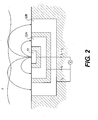
- MWD module 130 is shown to include a concentric, three-electrode sensor 50 useful for making measurements from which standoff and/or borehole caliper can be determined as disclosed herein. Although only a single sensor 50 is shown, it is understood that multiple sensors can be used.
- a second similar sensor can be disposed on MWD module 130 at a position that is 180 degrees from the sensor 50, and at the same depth as the sensor 50.
- one or more sensors 50 may be disposed at different heights on the MWD module 130.
- one or more sensors 50 can be positioned on an LWD module 120,120A.
- the MWD modules 130, 130A may also include an apparatus for generating electrical power to the downhole system.
- Such an electrical generator may include, for example, a mud turbine generator powered by the flow of the drilling fluid, but other power and/or battery systems may be employed additionally or alternatively.
- the well-site system is also shown to include an electronics subsystem comprising a controller 60 and a processor 70, which together can serve multiple functions.
- the controller 60 and processor 70 may be used to power and operate sensors, including sensor 50, and to receive and analyze data collected from the sensors, including sensor 50.
- the controller and processor for the sensor 50 need not be on the surface as shown but may be configured in any way known in the art.
- the controller and/or processor for the sensor 50 may be part of the MWD (or LWD) modules on which the sensor 50 is positioned or may be on-board the sensor 50 itself.
- the electronics subsystem (whether located on the surface or sub-surface on or within the tool or some combination thereof) includes machine-readable instructions for: exciting the primary electrode of a sensor with a single frequency; maintaining the primary electrode at a first potential and the secondary electrodes of the sensor at a second potential; simultaneously measuring current flow through each secondary electrode; and, estimating standoff and/or caliper from the current flow measurements.
- the sensor 50 includes a plurality of electrodes, particularly a primary electrode 51 and two secondary electrodes 52a, 52b.
- the electrodes are arranged in a concentric pattern, with the primary electrode 51 positioned in the center of the pattern.
- the primary or central electrode 51 can have a radius of about 1 ⁇ 4 inch
- the secondary electrodes 52a, 52b can have a radius of about 1 ⁇ 2 inch and 1 ⁇ 4 inch respectively.
- the size of each electrode can vary, yet still be effective in the systems and methods disclosed. In general, the size of the electrode impacts the depth of investigation, with smaller electrode sizes providing shallower measurements. Thus the size of electrode may be chosen depending on the anticipated size of standoff, with larger electrodes used for larger standoff.
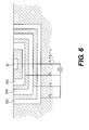
- additional secondary electrodes may optionally be used.
- the senor may include four electrodes, a primary electrode 51 and three secondary electrodes 52a, 52b, 52c. Similar to the embodiment illustrated in Fig. 2 , the electrodes in the embodiment of Fig. 6 are arranged in a concentric pattern, with the primary electrode being positioned in the center of the pattern. In general, the number of electrodes correlates to the range of standoff estimation, with more electrodes corresponding to a wider range of standoff estimation.
- the plurality of electrodes may also be arranged in a non-concentric pattern.
- the system may include multiple sensors.
- the system includes a pair of sensors.
- the system includes two or more pairs of sensors.
- the sensors in each pair are positioned 180 degrees apart on the tool.
- the sensors in each pair are positioned 180 degrees apart and at the same depth in the borehole.
- the choice of the number and arrangement of sensors may depend on the desired measurement. For example, a single sensor provides an estimate of standoff.
- a single sensor may also provide an estimate of caliper or an estimate of the shape of a borehole if multiple measurements are taken as the tool rotates. However, caliper can also be measured by taking simultaneous measurements from a pair of sensors positioned 180 degrees apart and at the same depth. In this way, various configurations of sensors, including providing sensors at different heights on the downhole tool, can provide data useful for estimating size and shape of the borehole.
- a power supply provides alternating current to the sensor.
- the power supply provides alternating current of a single excitation frequency to the primary electrode, while the primary electrode is maintained at one potential and the secondary electrodes are maintained at another potential.
- a first current I 1 to flow between the primary electrode and the first secondary electrode
- a second current I 2 to flow between the primary electrode and the second secondary electrode
- a third current I 3 to flow between the primary electrode and a third secondary electrode.
- each of the currents flowing between the primary electrode and a secondary electrode is unique. That is, for example, in Fig. 2 , the first current I 1 and second current I 2 , are different, and in Fig. 6 , the first current I 1 , the second current I 2 , and the third current I 3 are all different. In other words, in some embodiments having more than two secondary electrodes, the current flowing between the primary electrode and each secondary electrode is distinct.
- the excitation frequency is chosen, on the one hand, to be sufficiently low such that formation properties can be neglected (i.e. to alleviate or eliminate the impact of formation properties on standoff estimation) and on the other hand is chosen to be sufficiently high that the system can measure the impedance, or is chosen to be sufficiently high that impedance is easily measured.
- the excitation frequency is less than 100 kHz. In some embodiments, the excitation frequency ranges from about 1 kHz to less than 100 kHz, or from about 10 kHz to less than 100 kHz. Frequencies of 100 kHz and higher may be used, but in those embodiments it may be desirable to take into account formation properties when estimating standoff from the measured current flows.
- standoff is estimated by simultaneously measuring current flow between the primary electrode and each secondary electrode, calculating a quantity m from the measurements, and correlating the calculated m value with estimated standoff using a predetermined relationship between m and standoff.
- currents are measured by recording amplitude. In further embodiments, currents are measured by also recording the in-phase and in-quadrature components of amplitude.
- m I ⁇ 1 + I ⁇ 2 I ⁇ 2
- m ⁇ is calculated for every secondary electrode greater than 1 (i.e. a>1), and each m ⁇ is correlated with standoff using a predetermined relationship.
- m 2 , m 3 and m 4 can be calculated with I ⁇ being I 2 , I 3 and I 4 respectively.
- the calculated quantity m can then be correlated to an estimated standoff basis a predetermined relationship between m and standoff.
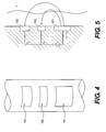
- the predetermined relationship illustrated in the graph of Fig. 3 was generated from simulations of Maxwell's equations performed for several standoff values ranging from 0.05 inch to 1 inch, for several mud properties and formation properties, and using an excitation frequency of 10 kHz.
- the same calculations can be generalized to a wide range of frequencies.
- additional m ⁇ measurements can be constructed based on the equations provided herein.
- each m ⁇ is provided on the same graph as a function of standoff, each m ⁇ curve will appear slightly offset from another m ⁇ curve along the standoff axis. Further, each m ⁇ curve may show different ranges of standoff where each shows optimal sensitivity. In some embodiments, the use of several m ⁇ measurements enables a better standoff estimation on a wider range.
- Fig. 3 curves corresponding to different formation properties overlay (i.e. the dashed curve and solid curve overlay and other curves are not evident due to the overlap), which means that the created measurement should provide an absolute estimate of the electric standoff, regardless of perturbing parameters such as mud and formation electrical properties.
- Fig. 3 also demonstrates that the measurement used appears as a ratio, thus compensating naturally for electronics drifts and calibrations (if current measurements are performed by equivalent electronic circuits).
- Fig. 3 also indicates that the zone of maximum sensitivity to standoff depends on electrode sizes, suggesting that more electrodes can be added to the sensor in order to obtain a wider range of standoff estimation.
Landscapes
- Physics & Mathematics (AREA)
- Engineering & Computer Science (AREA)
- Geology (AREA)
- Life Sciences & Earth Sciences (AREA)
- Mining & Mineral Resources (AREA)
- Environmental & Geological Engineering (AREA)
- Fluid Mechanics (AREA)
- Geophysics (AREA)
- General Life Sciences & Earth Sciences (AREA)
- Geochemistry & Mineralogy (AREA)
- General Physics & Mathematics (AREA)
- Remote Sensing (AREA)
- Electromagnetism (AREA)
- Geophysics And Detection Of Objects (AREA)
Priority Applications (5)
| Application Number | Priority Date | Filing Date | Title |
|---|---|---|---|
| EP11290610.2A EP2607929A1 (fr) | 2011-12-23 | 2011-12-23 | Systèmes et procédés de mesure au compas de trou de forage dans une boue à base d'huile |
| US14/366,682 US10415951B2 (en) | 2011-12-23 | 2012-12-20 | System and methods for measuring borehole caliper in oil-based mud |
| MX2014007771A MX2014007771A (es) | 2011-12-23 | 2012-12-20 | Sistema y metodos para medir el calibre de un agujero en el lodo a base de petroleo. |
| PCT/US2012/070863 WO2013096576A1 (fr) | 2011-12-23 | 2012-12-20 | Systèmes et procédés pour mesurer un calibre de trou de forage dans de la boue à base de pétrole |
| BR112014015717A BR112014015717A8 (pt) | 2011-12-23 | 2012-12-20 | sistema, e método |
Applications Claiming Priority (1)
| Application Number | Priority Date | Filing Date | Title |
|---|---|---|---|
| EP11290610.2A EP2607929A1 (fr) | 2011-12-23 | 2011-12-23 | Systèmes et procédés de mesure au compas de trou de forage dans une boue à base d'huile |
Publications (1)
| Publication Number | Publication Date |
|---|---|
| EP2607929A1 true EP2607929A1 (fr) | 2013-06-26 |
Family
ID=47553421
Family Applications (1)
| Application Number | Title | Priority Date | Filing Date |
|---|---|---|---|
| EP11290610.2A Withdrawn EP2607929A1 (fr) | 2011-12-23 | 2011-12-23 | Systèmes et procédés de mesure au compas de trou de forage dans une boue à base d'huile |
Country Status (5)
| Country | Link |
|---|---|
| US (1) | US10415951B2 (fr) |
| EP (1) | EP2607929A1 (fr) |
| BR (1) | BR112014015717A8 (fr) |
| MX (1) | MX2014007771A (fr) |
| WO (1) | WO2013096576A1 (fr) |
Cited By (1)
| Publication number | Priority date | Publication date | Assignee | Title |
|---|---|---|---|---|
| CN109884691A (zh) * | 2019-03-06 | 2019-06-14 | 中煤科工集团西安研究院有限公司 | 用于随采地震信号的强单频和随机噪声压制方法及系统 |
Families Citing this family (11)
| Publication number | Priority date | Publication date | Assignee | Title |
|---|---|---|---|---|
| MX2016011719A (es) * | 2014-04-08 | 2016-11-07 | Halliburton Energy Services Inc | Herramienta de generacion de imagenes de paredes de pozos con una cara acanalada de contacto con las paredes. |
| US10254431B2 (en) | 2014-12-30 | 2019-04-09 | Halliburton Energy Services, Inc. | Laterolog array tool for performing galvanic measurement |
| WO2016168322A1 (fr) * | 2015-04-13 | 2016-10-20 | Schlumberger Technology Corporation | Entraînement par le haut conjointement avec entrée par le haut et ligne insérée à travers ceux-ci pour collecte de données à travers le train de tiges de forage |
| US10753198B2 (en) | 2015-04-13 | 2020-08-25 | Schlumberger Technology Corporation | Downhole instrument for deep formation imaging deployed within a drill string |
| US10900305B2 (en) | 2015-04-13 | 2021-01-26 | Schlumberger Technology Corporation | Instrument line for insertion in a drill string of a drilling system |
| US9880311B2 (en) * | 2015-04-29 | 2018-01-30 | Schlumberger Technology Corporation | Wear resistant electrodes for downhole imaging |
| US9989665B2 (en) | 2015-04-29 | 2018-06-05 | Schlumberger Technology Corporation | Wear resistant electrodes for downhole imaging |
| CA2991566C (fr) * | 2015-08-17 | 2019-09-24 | Halliburton Energy Services, Inc. | Procede et article pour evaluer un effet de boue dans une mesure d'outil d'imagerie |
| EP3147449A1 (fr) | 2015-09-24 | 2017-03-29 | Services Pétroliers Schlumberger | Systèmes et procédés de détermination de centre d'outil, limite du trou de forage et/ou de paramètre de boue |
| WO2017082860A1 (fr) * | 2015-11-09 | 2017-05-18 | Halliburton Energy Services, Inc. | Déterminer des paramètres de trou de forage au moyen de compas de micro-résistivité et à ultrasons |
| CN114754719B (zh) * | 2022-05-07 | 2023-10-20 | 淮北兴业建设工程项目管理有限公司 | 一种水利工程施工用土壤厚度检测装置 |
Citations (5)
| Publication number | Priority date | Publication date | Assignee | Title |
|---|---|---|---|---|
| US5426368A (en) * | 1992-02-12 | 1995-06-20 | Schlumberger Technology Corporation | Logging method and apparatus for investigating geometrical characteristics of a borehole and for investigating formation resistivity |
| US5899958A (en) * | 1995-09-11 | 1999-05-04 | Halliburton Energy Services, Inc. | Logging while drilling borehole imaging and dipmeter device |
| GB2414081A (en) * | 2004-05-12 | 2005-11-16 | Schlumberger Holdings | Formation imaging while drilling in non-conductive mud |
| US20090166035A1 (en) * | 2007-12-26 | 2009-07-02 | Almaguer James S | Borehole Imaging and Orientation of Downhole Tools |
| EP2182393A1 (fr) * | 2008-10-31 | 2010-05-05 | Services Pétroliers Schlumberger | Outil pour l'imagerie d'un environnement d'extraction |
Family Cites Families (14)
| Publication number | Priority date | Publication date | Assignee | Title |
|---|---|---|---|---|
| US3973188A (en) * | 1972-04-18 | 1976-08-03 | Schlumberger Limited | Method and apparatus for the determination of the thickness of a mudcake layer on a borehole wall traversing a subsurface earth formation |
| FR2463939A1 (fr) * | 1979-08-17 | 1981-02-27 | Inst Francais Du Petrole | Perfectionnement a la methode et aux dispositifs de mesure de la resistivite electrique de formations geologiques |
| CA1185351A (fr) | 1981-03-10 | 1985-04-09 | Robert A. Broding | Systeme de televisionnement pour trou de forage utilisant plusieurs sous-systemes transducteurs |
| US4692908A (en) * | 1982-03-24 | 1987-09-08 | Schlumberger-Doll Research | Method and apparatus for investigating stand-off in a borehole |
| US4692707A (en) * | 1983-07-06 | 1987-09-08 | Schlumberger Technology Corporation | Method and apparatus for measuring the earth formation resistivity of a plurality of radial regions around a borehole |
| US4675610A (en) * | 1985-07-31 | 1987-06-23 | Chevron Research Company | Method of logging an earth formation penetrated by a borehole to provide an improved estimate of impedance distribution with depth using a single continuously emitting current electrode and a multiplicity of potential electrodes of a moving logging array |
| US4703279A (en) * | 1985-07-31 | 1987-10-27 | Chevron Research Company | Method of interpreting impedance distribution of an earth formation penetrated by a borehole using precursor data provided by a moving logging array having a single continuously emitting current electrode and a multiplicity of potential electrodes |
| US6671623B1 (en) | 1999-10-15 | 2003-12-30 | Schlumberger Technology Corporation | Methods and system for characterizing the response of subsurface measurements to determine wellbore and formation characteristics |
| GB2364079B (en) | 2000-06-28 | 2004-11-17 | Renovus Ltd | Drill bits |
| US7066282B2 (en) * | 2003-12-23 | 2006-06-27 | Schlumberger Technology Corporation | Apparatus and methods for measuring formation characteristics in presence of conductive and non-conductive muds |
| US7323868B2 (en) * | 2005-09-21 | 2008-01-29 | General Dynamics Advanced Information Systems, Inc. | System and method for temperature independent measurement of standoff distance using an eddy current sensor |
| DE602006005922D1 (de) * | 2006-07-28 | 2009-05-07 | Siemens Ag | Verfahren zur Bestimmung des Durchmessers eines Loches in einem Werkstück |
| US7689363B2 (en) | 2007-05-15 | 2010-03-30 | Baker Hughes Incorporated | Dual standoff resistivity imaging instrument, methods and computer program products |
| US8174266B2 (en) * | 2008-07-23 | 2012-05-08 | Baker Hughes Incorporated | Multi-resolution borehole resistivity imaging |
-
2011
- 2011-12-23 EP EP11290610.2A patent/EP2607929A1/fr not_active Withdrawn
-
2012
- 2012-12-20 WO PCT/US2012/070863 patent/WO2013096576A1/fr active Application Filing
- 2012-12-20 BR BR112014015717A patent/BR112014015717A8/pt not_active IP Right Cessation
- 2012-12-20 US US14/366,682 patent/US10415951B2/en active Active
- 2012-12-20 MX MX2014007771A patent/MX2014007771A/es unknown
Patent Citations (5)
| Publication number | Priority date | Publication date | Assignee | Title |
|---|---|---|---|---|
| US5426368A (en) * | 1992-02-12 | 1995-06-20 | Schlumberger Technology Corporation | Logging method and apparatus for investigating geometrical characteristics of a borehole and for investigating formation resistivity |
| US5899958A (en) * | 1995-09-11 | 1999-05-04 | Halliburton Energy Services, Inc. | Logging while drilling borehole imaging and dipmeter device |
| GB2414081A (en) * | 2004-05-12 | 2005-11-16 | Schlumberger Holdings | Formation imaging while drilling in non-conductive mud |
| US20090166035A1 (en) * | 2007-12-26 | 2009-07-02 | Almaguer James S | Borehole Imaging and Orientation of Downhole Tools |
| EP2182393A1 (fr) * | 2008-10-31 | 2010-05-05 | Services Pétroliers Schlumberger | Outil pour l'imagerie d'un environnement d'extraction |
Cited By (2)
| Publication number | Priority date | Publication date | Assignee | Title |
|---|---|---|---|---|
| CN109884691A (zh) * | 2019-03-06 | 2019-06-14 | 中煤科工集团西安研究院有限公司 | 用于随采地震信号的强单频和随机噪声压制方法及系统 |
| CN109884691B (zh) * | 2019-03-06 | 2020-10-27 | 中煤科工集团西安研究院有限公司 | 用于随采地震信号的强单频和随机噪声压制方法及系统 |
Also Published As
| Publication number | Publication date |
|---|---|
| BR112014015717A2 (pt) | 2017-06-13 |
| MX2014007771A (es) | 2015-03-23 |
| BR112014015717A8 (pt) | 2017-07-04 |
| US20150012217A1 (en) | 2015-01-08 |
| US10415951B2 (en) | 2019-09-17 |
| WO2013096576A1 (fr) | 2013-06-27 |
Similar Documents
| Publication | Publication Date | Title |
|---|---|---|
| US10415951B2 (en) | System and methods for measuring borehole caliper in oil-based mud | |
| US8030937B2 (en) | Multiple frequency based leakage correction for imaging in oil based muds | |
| US8749243B2 (en) | Real time determination of casing location and distance with tilted antenna measurement | |
| AU2013338324B2 (en) | Passive magnetic ranging for SAGD and relief wells via a linearized trailing window Kalman filter | |
| AU771334B2 (en) | Uncompensated electromagnetic wave resistivity tool for bed boundary detection and invasion profiling | |
| US10119389B2 (en) | Drilling collision avoidance apparatus, methods, and systems | |
| US20090164127A1 (en) | Method and apparatus for optimizing magnetic signals and detecting casing and resistivity | |
| WO2016025245A1 (fr) | Appareil, systèmes et procédés de télémétrie de puits | |
| US20140216734A1 (en) | Casing collar location using elecromagnetic wave phase shift measurement | |
| EP3080389A1 (fr) | Détermination et affichage de résistivité apparente de données électromagnétiques transitoires de fond de trou | |
| US8441269B2 (en) | Determining formation properties while drilling | |
| EP2773987B1 (fr) | Systèmes et méthodologie de détection d'une structure conductrice | |
| US9650888B2 (en) | Multi-mode measurements with a downhole tool using conformable sensors | |
| US9933543B2 (en) | Downhole inspection, detection, and imaging using conformable sensors | |
| US10386526B2 (en) | Methods and systems for determining formation properties and pipe properties using ranging measurements | |
| US9823380B2 (en) | Compensated borehole and pipe survey tool with conformable sensors | |
| US10677955B2 (en) | Two part magnetic field gradient sensor calibration | |
| EP4234880A2 (fr) | Procédé d'excitation de surfaces multiples pour déterminer un emplacement d'opérations de forage sur des puits existants |
Legal Events
| Date | Code | Title | Description |
|---|---|---|---|
| AK | Designated contracting states |
Kind code of ref document: A1 Designated state(s): AL AT BE BG CH CY CZ DE DK EE ES FI FR GB GR HR HU IE IS IT LI LT LU LV MC MK MT NL NO PL PT RO RS SE SI SK SM TR |
|
| AX | Request for extension of the european patent |
Extension state: BA ME |
|
| PUAI | Public reference made under article 153(3) epc to a published international application that has entered the european phase |
Free format text: ORIGINAL CODE: 0009012 |
|
| 17P | Request for examination filed |
Effective date: 20131223 |
|
| RBV | Designated contracting states (corrected) |
Designated state(s): AL AT BE BG CH CY CZ DE DK EE ES FI FR GB GR HR HU IE IS IT LI LT LU LV MC MK MT NL NO PL PT RO RS SE SI SK SM TR |
|
| 17Q | First examination report despatched |
Effective date: 20170628 |
|
| STAA | Information on the status of an ep patent application or granted ep patent |
Free format text: STATUS: THE APPLICATION IS DEEMED TO BE WITHDRAWN |
|
| 18D | Application deemed to be withdrawn |
Effective date: 20171109 |