EP2607065A1 - Pneumatic tire and manufacturing method of the same - Google Patents
Pneumatic tire and manufacturing method of the same Download PDFInfo
- Publication number
- EP2607065A1 EP2607065A1 EP12196688.1A EP12196688A EP2607065A1 EP 2607065 A1 EP2607065 A1 EP 2607065A1 EP 12196688 A EP12196688 A EP 12196688A EP 2607065 A1 EP2607065 A1 EP 2607065A1
- Authority
- EP
- European Patent Office
- Prior art keywords
- tread
- rubber
- width direction
- tire width
- winding
- Prior art date
- Legal status (The legal status is an assumption and is not a legal conclusion. Google has not performed a legal analysis and makes no representation as to the accuracy of the status listed.)
- Granted
Links
- 238000004519 manufacturing process Methods 0.000 title claims description 20
- 229920001971 elastomer Polymers 0.000 claims abstract description 226
- 239000005060 rubber Substances 0.000 claims abstract description 226
- 238000004804 winding Methods 0.000 claims abstract description 144
- 230000002093 peripheral effect Effects 0.000 claims description 15
- 238000000034 method Methods 0.000 description 15
- 238000010276 construction Methods 0.000 description 11
- 239000011324 bead Substances 0.000 description 10
- 230000000052 comparative effect Effects 0.000 description 9
- 230000007547 defect Effects 0.000 description 6
- 230000020169 heat generation Effects 0.000 description 5
- 239000011248 coating agent Substances 0.000 description 4
- 238000000576 coating method Methods 0.000 description 4
- 239000000945 filler Substances 0.000 description 3
- 230000003014 reinforcing effect Effects 0.000 description 3
- 239000005062 Polybutadiene Substances 0.000 description 2
- VYPSYNLAJGMNEJ-UHFFFAOYSA-N Silicium dioxide Chemical compound O=[Si]=O VYPSYNLAJGMNEJ-UHFFFAOYSA-N 0.000 description 2
- 230000033228 biological regulation Effects 0.000 description 2
- 238000001125 extrusion Methods 0.000 description 2
- 229920003049 isoprene rubber Polymers 0.000 description 2
- 229920002857 polybutadiene Polymers 0.000 description 2
- 238000003825 pressing Methods 0.000 description 2
- 230000000630 rising effect Effects 0.000 description 2
- 229920001875 Ebonite Polymers 0.000 description 1
- 244000043261 Hevea brasiliensis Species 0.000 description 1
- 229910000831 Steel Inorganic materials 0.000 description 1
- 239000003963 antioxidant agent Substances 0.000 description 1
- 230000003078 antioxidant effect Effects 0.000 description 1
- 229920005549 butyl rubber Polymers 0.000 description 1
- 239000006229 carbon black Substances 0.000 description 1
- 239000003795 chemical substances by application Substances 0.000 description 1
- 238000009826 distribution Methods 0.000 description 1
- 230000000694 effects Effects 0.000 description 1
- 238000009434 installation Methods 0.000 description 1
- 238000002156 mixing Methods 0.000 description 1
- 238000000465 moulding Methods 0.000 description 1
- 229920003052 natural elastomer Polymers 0.000 description 1
- 229920001194 natural rubber Polymers 0.000 description 1
- 238000011056 performance test Methods 0.000 description 1
- 239000004014 plasticizer Substances 0.000 description 1
- 239000002994 raw material Substances 0.000 description 1
- 239000000377 silicon dioxide Substances 0.000 description 1
- 239000010959 steel Substances 0.000 description 1
- 229920003048 styrene butadiene rubber Polymers 0.000 description 1
- 238000004073 vulcanization Methods 0.000 description 1
Images





Classifications
-
- B—PERFORMING OPERATIONS; TRANSPORTING
- B60—VEHICLES IN GENERAL
- B60C—VEHICLE TYRES; TYRE INFLATION; TYRE CHANGING; CONNECTING VALVES TO INFLATABLE ELASTIC BODIES IN GENERAL; DEVICES OR ARRANGEMENTS RELATED TO TYRES
- B60C11/00—Tyre tread bands; Tread patterns; Anti-skid inserts
- B60C11/0008—Tyre tread bands; Tread patterns; Anti-skid inserts characterised by the tread rubber
-
- B—PERFORMING OPERATIONS; TRANSPORTING
- B29—WORKING OF PLASTICS; WORKING OF SUBSTANCES IN A PLASTIC STATE IN GENERAL
- B29D—PRODUCING PARTICULAR ARTICLES FROM PLASTICS OR FROM SUBSTANCES IN A PLASTIC STATE
- B29D30/00—Producing pneumatic or solid tyres or parts thereof
- B29D30/06—Pneumatic tyres or parts thereof (e.g. produced by casting, moulding, compression moulding, injection moulding, centrifugal casting)
- B29D30/08—Building tyres
-
- B—PERFORMING OPERATIONS; TRANSPORTING
- B29—WORKING OF PLASTICS; WORKING OF SUBSTANCES IN A PLASTIC STATE IN GENERAL
- B29D—PRODUCING PARTICULAR ARTICLES FROM PLASTICS OR FROM SUBSTANCES IN A PLASTIC STATE
- B29D30/00—Producing pneumatic or solid tyres or parts thereof
- B29D30/06—Pneumatic tyres or parts thereof (e.g. produced by casting, moulding, compression moulding, injection moulding, centrifugal casting)
- B29D30/52—Unvulcanised treads, e.g. on used tyres; Retreading
- B29D30/58—Applying bands of rubber treads, i.e. applying camel backs
- B29D30/60—Applying bands of rubber treads, i.e. applying camel backs by winding narrow strips
-
- Y—GENERAL TAGGING OF NEW TECHNOLOGICAL DEVELOPMENTS; GENERAL TAGGING OF CROSS-SECTIONAL TECHNOLOGIES SPANNING OVER SEVERAL SECTIONS OF THE IPC; TECHNICAL SUBJECTS COVERED BY FORMER USPC CROSS-REFERENCE ART COLLECTIONS [XRACs] AND DIGESTS
- Y10—TECHNICAL SUBJECTS COVERED BY FORMER USPC
- Y10T—TECHNICAL SUBJECTS COVERED BY FORMER US CLASSIFICATION
- Y10T152/00—Resilient tires and wheels
- Y10T152/10—Tires, resilient
- Y10T152/10495—Pneumatic tire or inner tube
Definitions
- the present invention relates to a pneumatic tire having a tread rubber, and a manufacturing method of the same.
- JP-A-2006-130 880 discloses a pneumatic tire structured such that a ribbon rubber is wound from a starting point which is positioned in a center portion of a tread toward one side in a tire width direction in a tire meridian cross section, is next folded back to the other side in the tire width direction in a tread end on the one side, and is wound toward a tread end on the other side beyond the starting point, and a winding start end and a winding terminal end of the ribbon rubber are arranged in a center portion of the tread rubber (in the vicinity of a tire equator).
- JP-A-2002-46 194 discloses a pneumatic tire such that a ribbon rubber is wound from a tread end on one side in a tire width direction as a start point toward a tread end on the other side, is next folded back to the one side in the tire width direction at the tread end on the other side, and is wound toward the tread end on the one side, and a winding start end and a winding terminal end of the ribbon rubber are arranged in the tread ends.
- the present invention has been made by paying attention to the problem mentioned above, and an object of the present invention is to provide a pneumatic tire which suppresses a defect and has an improved high-speed durability, and a manufacturing method of the same.
- the present invention employs the following means for achieving the object.
- a pneumatic tire including a tread rubber that is formed by a ribbon rubber which is spirally wound around a tire rotating axis, wherein the ribbon rubber is wound from a start point which is positioned closer to a center side than tread ends toward one side in a tire width direction in a tire meridian cross section, is next folded back to the other side in the tire width direction at the tread end on the one side, is wound toward the tread end on the other side beyond the start point, is next folded back to the one side in the tire width direction at the tread end on the other side, and is wound toward a terminal end which is positioned closer to the center side than the tread ends, wherein the ribbon rubber has a winding start end and a winding terminal end in the vicinity of the tread ends avoiding the tread ends and the tread center portion.
- the winding start end and the winding terminal end of the ribbon rubber are arranged in the vicinity of the tread end avoiding the tread center portion, an influence of the centrifugal force is reduced in comparison with the case that the winding start end and the winding terminal end are arranged in the tread center portion, and it is possible to improve the high-speed durability.
- the winding start end and the winding terminal end are arranged in the vicinity of the tread end avoiding the tread ends, it is possible to appropriately press the ribbon rubber at the winding time, and it is possible to suppress a defect.
- the winding terminal end of the ribbon rubber is arranged at a position at which a main groove extending in a tire peripheral direction is formed. According to this structure, at the forming position of the main groove, the thickness of the rubber becomes thinner, and heat generation at the time of the high-speed rotation is suppressed in conjunction therewith. Therefore, it is possible to suppress the failure caused by such a heat generation, and it is possible to improve the high-speed durability.
- the tread rubber has a three-layer structure portion in which the ribbon rubber wound toward the one side in the tire width direction is folded back, is wound toward the other side in the tire width direction, is thereafter folded back again and is wound toward the one side in the tire width direction, at the position closer to the center side than the tread ends. Since the tire having the three-layer structure mentioned above can be manufactured without narrowing the winding pitch of the ribbon rubber as well as raising the ribbon rubber, on the contrary, even in a state in which the winding pitch of the ribbon rubber is widened and the ribbon rubber is laid down, it is possible to easily secure the thickness of the tread rubber.
- the ribbon rubber forms a first layer which has the vicinity portion of the tread end on the one side in the tire width direction as a start point, among the vicinity portions of the pair treads to the tread end on the other side in the tire width direction, next forms a second layer which is folded back to the one side in the tire width direction at the tread end on the other side in the tire width direction and reaches the tread end on the one side beyond the start point, and next forms a third layer which is folded back to the other side in the tire width direction at the tread end on the one side and has the vicinity portion of the tread end on the other side in the tire width direction as a terminal end.
- a manufacturing method of a pneumatic tire including a tread rubber forming step of forming a tread rubber by spirally winding a ribbon rubber around a tire rotating axis, wherein the tread rubber forming step includes a stage of winding the ribbon rubber from a start point which is positioned closer to a center side than tread ends in a tire meridian cross section toward one side in a tire width direction, next folding back the ribbon rubber to the other side in the tire width direction at the tread end on the one side, winding the ribbon rubber toward the tread end on the other side beyond the start point, next folding back the ribbon rubber to the one side in the tire width direction at the tread end on the other side, and winding the ribbon rubber toward a terminal end which is positioned closer to the center side than the tread ends, and the ribbon rubber has a winding start end and a winding terminal end in the vicinity portion of the tread end avoiding the tread end and the tread center
- the tread rubber can be formed by one winding process without disconnecting the ribbon rubber from the start point to the terminal end, it is possible to improve a forming efficiency of the tread rubber. Further, as mentioned above, it is possible to improve the high-speed durability, and it is further possible to suppress defects.
- the winding terminal end at the forming position of the main groove extending in the tire peripheral direction.
- the three-layer structure portion In order to easily secure the thickness of the tread rubber, it is desirable to form the three-layer structure portion by folding back the ribbon rubber which is wound toward the one side in the tire width direction, at the position which is closer to the center side than the tread ends, winding the ribbon rubber toward the other side in the tire width direction, and thereafter folding back the ribbon rubber again so as to wind toward the one side in the tire width direction.
- a toroidal carcass layer 7 is arranged between a pair of bead portions 1, and an end portion thereof is locked in a state of being wound up via the bead core 1a.
- the carcass layer 7 is constructed by at least one (two in the present embodiment) carcass ply, and the carcass ply is formed by coating a cord extending at an angle of about 90° with respect to the tire peripheral direction with a topping rubber.
- An inner liner rubber 5 for retaining a pneumatic pressure is arranged in an inner periphery of the carcass layer 7.
- the bead portion 1 is provided on an outer side of the carcass layer 7 with a rim strip rubber 4 which comes into contact with a rim (not shown) at the time of installation of the rim.
- the side wall portion 2 is provided on the outer side of the carcass layer 7 with a side wall rubber 9.
- each of the rim strip rubber 4 and the side wall rubber 9 is formed by a conductive rubber.
- a belt layer 6 constructed by a plurality of (two in the present embodiment) belt plies is arranged on the outer side of the carcass layer 7.
- Each of the belt plies is formed by coating a cord which extends while inclining with respect to the tire peripheral direction with a topping rubber, and is laminated in such a manner that the cord intersects inversely to each other between the plies.
- a belt reinforcing layer 8 formed by coating a cord which substantially extends in the tire peripheral direction with a topping rubber is arranged at an outer periphery of the belt layer 6, however, may be omitted as occasion demands.
- a tread rubber 10 is provided at the outer periphery of the belt layer 6.
- the tread rubber 10 has a cap portion 12 which constructs a ground plane, and a base portion 11 which is provided on an inner side in the tire diametrical direction of the cap portion 12.
- the base 11 is made of a different kind of rubber from the cap 12.
- a raw material rubber of the rubber layer mentioned above there can be listed up a natural rubber, a styrene butadiene rubber (SBR), a butadiene rubber (BR), an isoprene rubber (IR), an isobutylene isoprene rubber (IIR) and the like, and they are used independently or are used by mixing two or more. Further, the rubbers are reinforced by a filler such as carbon black or silica, and are appropriately blended with a vulcanizing agent, a vulcanization accelerator, a plasticizer, an antioxidant or the like.
- SBR styrene butadiene rubber
- BR butadiene rubber
- IR isoprene rubber
- IIR isobutylene isoprene rubber
- the tread rubber 10, particularly the cap portion 12 is formed by a so-called ribbon winding construction method.
- the ribbon winding construction method is a construction method for forming a rubber member having a desired cross sectional shape by spirally winding a narrow and unvulcanized ribbon rubber 20 shown in Fig. 3 around a tire rotating axis (refer to Fig. 2 and Fig. 5 ).
- the tread rubber 10 formed by the ribbon winding construction method has a winding start end S1 and a winding terminal end E1 of the ribbon rubber 20, as shown in Fig. 7C .
- the winding start end S1, the winding terminal end E1 and a moving route of a winding position can be checked out in a tire meridian cross section. Details thereof will be mentioned later.
- a main groove 15 extending in the tire peripheral direction is formed on a surface of the tread rubber 10.
- a projection is provided in a tire mold which is used for the vulcanizing treatment, and the main groove 15 is formed by pressing the projection against the tread rubber 10.
- the tread rubber 10 is appropriately provided with a transverse groove which extends in a direction intersecting the main groove 15.
- the tread rubber 10 shown in Fig. 1 is formed by the ribbon winding construction method.
- a forming step of the tread rubber 10 includes a stage which winds the ribbon rubber 20 supplied from a ribbon rubber forming device 30 to a rotation support body 31, while rotating the rotation support body 31, as shown in Fig. 2 .
- the rubber ribbon 20 is formed by a nonconductive rubber, as shown in Fig. 3 .
- a lower side in Fig. 3 comes to an inner peripheral side which is opposed to the rotation support body 31, at the winding time.
- the width and the thickness of the ribbon rubber (which may be called as a rubber strip) are not particularly limited, however, are preferably desirable to be set between 15 mm and 40 mm in width and between 0.5 mm to 3.0 mm in thickness.
- the ribbon rubber forming device 30 is structured so as to form the ribbon rubber 20 by extruding the rubber.
- the rotation support body 31 is structured so as to achieve a rotation in a direction R around an axis 31a, and a movement in an axial direction.
- a control device 32 carries out the operation control of the ribbon rubber forming device 30 and the rotation support body 31.
- a cross section of the ribbon rubber 20 is formed as a triangular shape, however, is not limited to this, but may also be formed in other shapes such as an oval shape, a quadrangular shape and the like.
- the rotation support body 31 is structured so as to move in the axial direction, however, the ribbon rubber forming device 30 may be moved with respect to the rotation support body 31. In other words, it is possible to employ any structure as long as the rotation support body 31 can move relatively along the axis direction with respect to the ribbon rubber forming device 30.
- the base portion 11 is formed in an outer peripheral surface of the rotation support body 31.
- the belt layer 6 and the belt reinforcing layer 8 are provided previously on an outer peripheral surface of the rotation support body 31 (refer to Fig. 1 ), and the base portion 11 is formed on them.
- the base portion 11 may be formed by any one of a so-called extrusion molding method and a ribbon winding construction method.
- the extrusion molding method is a construction method which has a step of extruding and molding an unvulcanized band-like rubber member having a desired cross sectional shape, and jointing end portions thereof so as to form annularly.
- a winding pitch P20 of the ribbon rubber 20 is set to be smaller than a ribbon width W20 of the ribbon rubber 20. Accordingly, the adjacent ribbon rubbers 20 and 20 are spirally wound in a state of being in contact with each other.
- An arrow D indicates a moving direction of the ribbon winding position, and the adjacent ribbon rubbers 20 overlap their edge portions with each other along the direction.
- Fig. 6 conceptually shows a moving route of the winding position of the ribbon rubber 20, in the forming step of the tread rubber shown in Fig. 4 .
- one side (a right side in the drawing) of the tire width direction WD in the tire meridian cross section is defined as WD1
- the other side is defined as WD2 (a left side in the drawing).
- the ribbon rubber is wound from the start point S1 which is positioned closer to the center side than tread ends P1 and P2 in the tire meridian cross section toward the tire width direction WD1 side.
- the ribbon rubber is folded back to a tire width direction WD2 side at the tread end P2 closer to the WD1 side, and is wound toward the tread end P1 on the WD2 side beyond the start point S1.
- the ribbon rubber is folded back to the tire width direction WD1 side at the tread end P1 in the WD2 side, and is wound toward the end point E1 which is positioned closer to the center side than the tread end P2. Further, as shown in Fig.
- Fig. 7 is drawn conceptually, and a cross sectional area ratio of each of the ribbon rubbers 20 with respect to the tread rubber 10 may be smaller.
- Fig. 7A corresponds to the stage in Fig. 4B , and the winding position of the ribbon rubber moves to the tire width direction WD1 side (the right side) by defining the tread end vicinity portion Ar1 on the tire width direction WD2 side (the left side) among the pair of tread end vicinity portions Ar1 and Ar2 as the start point S1, and reaches the tread end P2 on the tire width direction WD1 side (the right side). Accordingly, a first layer L1 of the ribbon rubber 20 is formed.
- Fig. 7B corresponds to the stage in Fig. 4C , and the winding position of the ribbon rubber folds back to the tire width direction WD2 side (the left side) at the tread end P2 on the tire width direction WD1 side (the right side), goes over the start point S1, and reaches the tread end P1 on the tire width direction WD2 side (the left side). Accordingly, a second layer L2 of the ribbon rubber 20 is formed.
- Fig. 7C corresponds to the stage in Fig. 4D , and the winding position of the ribbon rubber folds back to the tire width direction WD1 side (the right side) at the tread end P1 in the tire width direction WD2 side (the left side), reaches the tread end vicinity portion Ar2 in the tire width direction WD1 side (the right side), and defines this as the end point E1. Accordingly, a third layer L3 of the ribbon rubber 20 is formed.
- the pneumatic tire of the present embodiment provides a pneumatic tire T in which the tread rubber 10 is formed by the ribbon rubber 20 spirally wound around the tire rotating axis, wherein the ribbon rubber 20 is wound toward the one side (WD1) in the tire width direction WD from the start point S1 which is positioned closer to the center side than the tread ends P1 and P2 in the tire meridian cross section, is next folded back to the other side (WD2) in the tire width direction WD at the tread end P2 on the one side (WD1), goes over the start point S1 so as to be wound toward the tread end P1 on the other side (WD2), is next folded back to the one side (WD1) in the tire width direction WD at the tread end P1 on the other side (WD2), and is wound toward the end point E1 which is positioned closer to the center side than the tread ends P1 and P2, and wherein the ribbon rubber 20 has the winding start end S1 and the winding terminal end E1 in the tread end vicinity portions Ar1 and Ar2 avoiding the tread ends
- the manufacturing method of the pneumatic tire of the present embodiment is a manufacturing method of a pneumatic tire including a tread rubber forming step of forming the tread rubber 10 by spirally winding the ribbon rubber 20 around the tire rotating axis, wherein the tread rubber forming step includes: a stage of winding the ribbon rubber 20 from the start point S1 which is positioned closer to the center side than the tread ends P1 and P2 in the tire meridian cross section toward the one side (WD1) in the tire width direction WD; next folding back the ribbon rubber to the other side (WD2) in the tire width direction WD at the tread end P2 on the one side (WD1), winding the ribbon rubber toward the tread end P1 on the other side (WD2) beyond the start point S1; next folding back the ribbon rubber to the one side (WD1) in the tire width direction WD at the tread end P1 on the other side (WD2); and winding the ribbon rubber toward the end point E1 which is positioned closer
- the tread end vicinity portions Ar1 and Ar2 mean a range between 5 and 25 % of a tread rubber maximum width W from the tread ends P1 and P2 toward the center side.
- the tread rubber 10 can be formed by one winding process without disconnecting the ribbon rubber 20 from the start point S1 to the end point E1, it is possible to improve the forming efficiency of the tread rubber 10. Further, since the winding start end S1 and the winding terminal end E1 of the ribbon rubber 20 are arranged at the tread end vicinity portions Ar1 and Ar2 avoiding the tread center portion, it is possible to reduce the influence of the centrifugal force and to improve the high-speed durability, in comparison with the case that the winding start end S1 and the winding terminal end E1 are arranged in the tread center portion. In addition, since the winding start end S1 and the winding terminal end E1 are arranged at the tread end vicinity portions Ar1 and Ar2 avoiding the tread ends P1 and P2, it is possible to appropriately push the ribbon rubber 20, and it is possible to suppress the defect.
- the ribbon rubber 20 forms the first layer L1 which reaches the tread end P2 on the other side (WD1) in the tire width direction by defining a tread end vicinity portion Ar1 on the one side (WD2) in the tire width direction WD among the paired tread end vicinity portions Ar1 and Ar2 as the start point S1, next forms the second layer L2 which reaches the tread end P1 on the one side (WD2) beyond the start point S1 by folding back to the one side (WD2) in the tire width direction at the tread end P2 on the other side (WD1) in the tire width direction, and next forms the third layer L3 which defines the tread end vicinity portion Ar2 on the other side (WD1) in the tire width direction as the end point E1 by folding back to the other side (WD1) in the tire width direction at the tread end P1 on the one side (WD2).
- the thickness of the tread rubber 10 since it is possible to secure the thickness of the tread rubber 10 without narrowing the winding pitch P20 of the ribbon rubber 20 as well as raising the ribbon rubber 20, it is possible to improve both the securing of the thickness and the winding controllability of the ribbon rubber. Particularly, it is useful for forming the tire which requires a greater thickness such as a truck and a bus.
- the winding terminal end E2 of the ribbon rubber 20 is arranged at the forming position of the main groove 15 which extends in the tire peripheral direction, as shown in Fig. 8 .
- the forming position of the main groove 15 since the thickness of the rubber is reduced, and the heat generation at the time of the high-speed rotation is suppressed in conjunction therewith, it is possible to suppress failures which are caused by such a heat generation, and it is possible to further improve the high-speed durability.
- a winding start end S2 and a winding terminal end E3 of the ribbon rubber 20 may be arranged only at the one tread end vicinity portion Ar1 among the paired tread end vicinity portions Ar1 and Ar2, as shown in Fig. 9 .
- a winding method shown in Fig. 12 can be listed up.
- the ribbon rubber is wound toward the other side (WD1) in the tire width direction by defining the tread vicinity portion Ar1 on the one side (WD2) as the start point S2.
- the ribbon rubber is folded back at the position P3 so as to be wound toward the one side (WD2) in the tire width direction beyond the start point S2, is folded to the other side (WD1) in the tire width direction at the tread end P1 on the one side (WD2), and is wound toward the tread end P2 on the other side (WD1) beyond the start point S2.
- the ribbon rubber is folded back at the tread end P2 on the other side (WD1), and is wound to the terminal end E2 which is positioned closer to the center side than the tread end P2.
- the problem since it is possible to keep the tread end P2 and the winding terminal end E2 away from each other by folding back the winding terminal end E2, it is possible to further reduce the problem caused by the movement of the winding terminal end E2 closer to the tread end P2.
- the problem for example, there can be listed up a defect caused by a short pressing of the ribbon rubber by the following roller (stitcher),
- the winding start end S1 and the winding terminal end E1 are kept away at 180° in the tire peripheral direction.
- a radial force variation (RFV) is improved and a ground surface pressure distribution on a periphery becomes uniform as long as the winding start end S1 and the winding terminal end E1 are in a positional relationship which is symmetrical around the tire rotating axis, it is possible to improve the high-speed durability.
- the high-speed durability was evaluated by using a test tire having a tire size 215/45R17.
- the high-speed durability was tested on the basis of a condition about tire of a speed mark H (210 km/h) which was defined as load/speed performance test procedure by a supplementary provision 7 of Regulation No. 30 of Economic Commission for Europe (Regulation No. 30 Uniform Provisions Concerning the Approval of Pneumatic Tires for Motor Vehicles and Their Trailers).
- the high-speed durability was evaluated by traveling at a high speed by a drum tester until the tire broke down, according to a method of increasing the traveling speed at 10 km/h per ten minutes. Therefore, the higher speed indicates the more excellent high-speed durability.
- the tire was produced by arranging the winding start of the ribbon rubber to the center portion in the tire width direction, winding the ribbon rubber like a infinity symbol shape, and arranging the winding terminal end at the center portion (the equator portion) in the tire width direction (refer to JP-A-2006-130880 .
- the tread rubber was formed by winding the ribbon rubber via the route shown in Fig. 6 .
- the winding start end S1 and the winding terminal end E1 of the ribbon rubber 20 were arranged respectively at positions which were 12.5 % of the maximum width W of the tread rubber from the tread ends P1 and P2 toward the center side.
- the same structures as in the Comparative Example were applied with the exception of the above.
- the tread rubber was formed by winding the ribbon rubber via the route shown in Fig. 8 .
- the winding start end 52 and the winding terminal end E2 of the ribbon rubber 20 were arranged respectively at positions which were 20 % of the maximum width W of the tread rubber from the tread ends P1 and P2 toward the center side.
- the same structures as in the Comparative Example were applied with the exception of the above.
- the tread rubber was formed by winding the ribbon rubber via the route shown in Fig. 9 .
- the winding start end S2 and the winding terminal end E3 of the ribbon rubber 20 were arranged respectively at positions which were 24. % of the maximum width W of the tread rubber from the tread end P1 toward the center side.
- the same structures as in the Comparative Example were applied with the exception of the above.
- the tread rubber was formed by winding the ribbon rubber via the route shown in Fig. 10 .
- the winding start end S2 and the winding terminal end E2 of the ribbon rubber 20 were arranged respectively at positions which were 23.2 % of the maximum width W of the tread rubber from the tread ends P1 and P2 toward the center side.
- the same structures as in the Comparative Example were applied with the exception of the above.
- the tread rubber was formed by winding the ribbon rubber via the route shown in Fig. 12 .
- the winding start end S2 and the winding terminal end E2 of the ribbon rubber 20 were arranged respectively at positions which were 20 % the maximum width W of the tread rubber from the tread ends P1 and P2 toward the center side.
- the same structures as in the Comparative Example were applied with the exception of the above.
- Example 2 Example 3
- Example 4 High-speed durability 280 km/h 310km/h 310 km/h 300 km/h 290 km/h 300 km/h
- the failure was generated at 280 km/h, however, the speeds at which the failure was generated were higher in all the Examples 1 to 5 than in the Comparative Example, Accordingly, it is known that the high-speed durability is improved.
- the Example 4 is lower in the high-speed durability in comparison with the Examples 1 to 3 since the fold-back end of the ribbon rubber 20 exists at the tread intermediate portion between the paired tread end vicinity portions Ar1 and Ar2. Therefore, in the light of pursuit of the high-speed durability, it is thought to be preferable that the tread intermediate portion (including the tire equator) does not have any fold-back end.
- each of the embodiments it is possible to apply the structure employed in each of the embodiments to the other optional embodiment.
- the particular structure of each of the portions is not limited to the embodiments mentioned above, but can be variously modified within a range which does not deviate from the scope of the present invention.
Landscapes
- Engineering & Computer Science (AREA)
- Mechanical Engineering (AREA)
- Tyre Moulding (AREA)
- Tires In General (AREA)
Abstract
Description
- The present invention relates to a pneumatic tire having a tread rubber, and a manufacturing method of the same.
- Conventionally, there has been proposed a so-called ribbon winding construction method which forms a tread rubber by spirally winding an unvulcanized ribbon rubber around a tire rotating axis to an outer peripheral surface of an approximately cylindrical rotation support body, while overlapping a side edge thereof.
- As one example of a pneumatic tire in which the tread rubber is formed by the ribbon winding construction method, for example,
JP-A-2006-130 880 - As another example of the pneumatic tire which is manufactured by the ribbon winding construction method,
JP-A-2002-46 194 - However, in the pneumatic tire according to
JP-A-2006-130 880 - On the other hand, in the pneumatic tire according to
JP-A-2002-46 194 - The present invention has been made by paying attention to the problem mentioned above, and an object of the present invention is to provide a pneumatic tire which suppresses a defect and has an improved high-speed durability, and a manufacturing method of the same.
- The present invention employs the following means for achieving the object.
- In other words, according to the present invention, there is provided a pneumatic tire including a tread rubber that is formed by a ribbon rubber which is spirally wound around a tire rotating axis, wherein the ribbon rubber is wound from a start point which is positioned closer to a center side than tread ends toward one side in a tire width direction in a tire meridian cross section, is next folded back to the other side in the tire width direction at the tread end on the one side, is wound toward the tread end on the other side beyond the start point, is next folded back to the one side in the tire width direction at the tread end on the other side, and is wound toward a terminal end which is positioned closer to the center side than the tread ends, wherein the ribbon rubber has a winding start end and a winding terminal end in the vicinity of the tread ends avoiding the tread ends and the tread center portion.
- The vicinity of the tread ends means a range between 5 % and 25 % of a maximum width of the tread rubber from the tread ends toward the center side.
- As mentioned above, since the winding start end and the winding terminal end of the ribbon rubber are arranged in the vicinity of the tread end avoiding the tread center portion, an influence of the centrifugal force is reduced in comparison with the case that the winding start end and the winding terminal end are arranged in the tread center portion, and it is possible to improve the high-speed durability.
At the same time, since the winding start end and the winding terminal end are arranged in the vicinity of the tread end avoiding the tread ends, it is possible to appropriately press the ribbon rubber at the winding time, and it is possible to suppress a defect. - In order to suppress the failure caused by a heat generation, and further improve the high-speed durability, it is effective that the winding terminal end of the ribbon rubber is arranged at a position at which a main groove extending in a tire peripheral direction is formed. According to this structure, at the forming position of the main groove, the thickness of the rubber becomes thinner, and heat generation at the time of the high-speed rotation is suppressed in conjunction therewith. Therefore, it is possible to suppress the failure caused by such a heat generation, and it is possible to improve the high-speed durability.
- In the case that a tire having a thick tread rubber, for example, a tire for a truck and a tire for a bus is manufactured according to the ribbon winding construction method, it is often the case that a winding pitch of the ribbon rubber is narrowed and the ribbon rubber is set to a rising state. However, since it becomes hard to control the winding in conformity to the rising of the ribbon rubber, securing a thickness of the tread rubber comes to be a hard work.
- Consequently, in order to easily secure the thickness of the tread rubber, it is preferable that the tread rubber has a three-layer structure portion in which the ribbon rubber wound toward the one side in the tire width direction is folded back, is wound toward the other side in the tire width direction, is thereafter folded back again and is wound toward the one side in the tire width direction, at the position closer to the center side than the tread ends.
Since the tire having the three-layer structure mentioned above can be manufactured without narrowing the winding pitch of the ribbon rubber as well as raising the ribbon rubber, on the contrary, even in a state in which the winding pitch of the ribbon rubber is widened and the ribbon rubber is laid down, it is possible to easily secure the thickness of the tread rubber. - In order to realize the securing of the thickness of the tread rubber and a winding controllability of the ribbon rubber it is preferable that the ribbon rubber forms a first layer which has the vicinity portion of the tread end on the one side in the tire width direction as a start point, among the vicinity portions of the pair treads to the tread end on the other side in the tire width direction, next forms a second layer which is folded back to the one side in the tire width direction at the tread end on the other side in the tire width direction and reaches the tread end on the one side beyond the start point, and next forms a third layer which is folded back to the other side in the tire width direction at the tread end on the one side and has the vicinity portion of the tread end on the other side in the tire width direction as a terminal end.
- The pneumatic tire mentioned above is manufactured by a manufacturing method described below. In other words, according to the present invention, there is provided a manufacturing method of a pneumatic tire, including a tread rubber forming step of forming a tread rubber by spirally winding a ribbon rubber around a tire rotating axis,
wherein the tread rubber forming step includes a stage of winding the ribbon rubber from a start point which is positioned closer to a center side than tread ends in a tire meridian cross section toward one side in a tire width direction, next folding back the ribbon rubber to the other side in the tire width direction at the tread end on the one side, winding the ribbon rubber toward the tread end on the other side beyond the start point, next folding back the ribbon rubber to the one side in the tire width direction at the tread end on the other side, and winding the ribbon rubber toward a terminal end which is positioned closer to the center side than the tread ends, and the ribbon rubber has a winding start end and a winding terminal end in the vicinity portion of the tread end avoiding the tread end and the tread center portion. - According to the manufacturing method, since the tread rubber can be formed by one winding process without disconnecting the ribbon rubber from the start point to the terminal end, it is possible to improve a forming efficiency of the tread rubber. Further, as mentioned above, it is possible to improve the high-speed durability, and it is further possible to suppress defects.
- In order to improve the high-speed durability, it is preferable so arrange the winding terminal end at the forming position of the main groove extending in the tire peripheral direction.
- In order to easily secure the thickness of the tread rubber, it is desirable to form the three-layer structure portion by folding back the ribbon rubber which is wound toward the one side in the tire width direction, at the position which is closer to the center side than the tread ends, winding the ribbon rubber toward the other side in the tire width direction, and thereafter folding back the ribbon rubber again so as to wind toward the one side in the tire width direction.
- In order to realize the securing of the thickness of the tread rubber and the winding controllability of the ribbon rubber, it is preferable to form a first layer by moving the winding position of the ribbon rubber to the tread end on the other side in the tire width direction from the start point of the vicinity portion of the tread end on the one side in the tire width direction, among the vicinity portions of the pair treads, next form a second layer by folding back the winding position of the ribbon rubber to the one side in the tire width direction at the tread end on the other side in the tire width direction and moving to the tread end on the one side beyond the start point, and next form a third layer by folding back the winding position of the ribbon rubber to the other side in the tire width direction at the tread end on the one side and defining the vicinity portion of the tread end on the other side in the tire width direction as a terminal end.
-
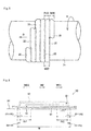
- Fig. 1
- is a tire meridian cross sectional view showing a pneumatic tire according to an embodiment of the present invention;
- Fig. 2
- is a view showing a manufacturing facility which is used in a forming step of a tread rubber;
- Fig. 3
- is a schematic cross sectional view of a ribbon rubber;
- Fig. 4
- is a cross sectional view schematically showing a forming step of the tread rubber;
- Fig. 5
- is a plan view showing a winding process of the ribbon rubber;
- Fig. 6
- is a conceptual view showing a moving route of a ribbon winding position;
- Fig. 7
- is a cross sectional view showing a winding process of the ribbon rubber;
- Fig. 8
- is a conceptual view showing another moving route of the ribbon winding position;
- Fig. 9
- is a conceptual view showing a different moving route from the above route of the ribbon winding position;
- Fig. 10
- is a conceptual view showing a different moving route from the above route of the ribbon winding position;
- Fig. 11
- is a conceptual view showing a different moving route from the above route of the ribbon winding position; and
- Fig. 12
- is a conceptual view showing a different moving route from the above route of the ribbon winding position.
- An embodiment of the present invention will be described blow with reference to the accompanying drawings. First of all, a description will be given of a structure of a pneumatic tire according to the present invention, and a description will be given next of a manufacturing method of the pneumatic tire according to the present invention.
- A pneumatic tire T shown in
Fig. 1 is provided with a pair ofbead portions 1,side wall portions 2 each of which extends to an outer side in a tire diametrical direction from each of thebead portions 1, and atread portion 3 which is connected to an outer end in the tire diametrical direction of each of theside wall portions 2. Anannular bead core 1a formed by coating a converged body of steel wires with a rubber, and abead filler 1b made of a hard rubber are arranged in thebead portion 1. - A
toroidal carcass layer 7 is arranged between a pair ofbead portions 1, and an end portion thereof is locked in a state of being wound up via thebead core 1a. Thecarcass layer 7 is constructed by at least one (two in the present embodiment) carcass ply, and the carcass ply is formed by coating a cord extending at an angle of about 90° with respect to the tire peripheral direction with a topping rubber. Aninner liner rubber 5 for retaining a pneumatic pressure is arranged in an inner periphery of thecarcass layer 7. - The
bead portion 1 is provided on an outer side of thecarcass layer 7 with arim strip rubber 4 which comes into contact with a rim (not shown) at the time of installation of the rim. Further, theside wall portion 2 is provided on the outer side of thecarcass layer 7 with aside wall rubber 9. In the present embodiment, each of therim strip rubber 4 and theside wall rubber 9 is formed by a conductive rubber. - In the
tread portion 3, abelt layer 6 constructed by a plurality of (two in the present embodiment) belt plies is arranged on the outer side of thecarcass layer 7. Each of the belt plies is formed by coating a cord which extends while inclining with respect to the tire peripheral direction with a topping rubber, and is laminated in such a manner that the cord intersects inversely to each other between the plies.
Abelt reinforcing layer 8 formed by coating a cord which substantially extends in the tire peripheral direction with a topping rubber is arranged at an outer periphery of thebelt layer 6, however, may be omitted as occasion demands. - In the
tread portion 3, atread rubber 10 is provided at the outer periphery of thebelt layer 6. Thetread rubber 10 has acap portion 12 which constructs a ground plane, and abase portion 11 which is provided on an inner side in the tire diametrical direction of thecap portion 12. Thebase 11 is made of a different kind of rubber from thecap 12. - As a raw material rubber of the rubber layer mentioned above, there can be listed up a natural rubber, a styrene butadiene rubber (SBR), a butadiene rubber (BR), an isoprene rubber (IR), an isobutylene isoprene rubber (IIR) and the like, and they are used independently or are used by mixing two or more. Further, the rubbers are reinforced by a filler such as carbon black or silica, and are appropriately blended with a vulcanizing agent, a vulcanization accelerator, a plasticizer, an antioxidant or the like.
- The
tread rubber 10, particularly thecap portion 12 is formed by a so-called ribbon winding construction method. The ribbon winding construction method is a construction method for forming a rubber member having a desired cross sectional shape by spirally winding a narrow andunvulcanized ribbon rubber 20 shown inFig. 3 around a tire rotating axis (refer toFig. 2 andFig. 5 ).
Thetread rubber 10 formed by the ribbon winding construction method has a winding start end S1 and a winding terminal end E1 of theribbon rubber 20, as shown inFig. 7C . The winding start end S1, the winding terminal end E1 and a moving route of a winding position can be checked out in a tire meridian cross section. Details thereof will be mentioned later. - Further, with a vulcanizing treatment being applied, a
main groove 15 extending in the tire peripheral direction is formed on a surface of thetread rubber 10. A projection is provided in a tire mold which is used for the vulcanizing treatment, and themain groove 15 is formed by pressing the projection against thetread rubber 10. Though an illustration will be omitted, thetread rubber 10 is appropriately provided with a transverse groove which extends in a direction intersecting themain groove 15. - Next, a description will be given of a method of manufacturing the pneumatic tire T. Since the pneumatic tire T can be manufactured in the same manner as in a conventional tire manufacturing method, with the exception of a point relating to the
tread rubber 10, a description will be given mainly of a forming step of thetread rubber 10. - The
tread rubber 10 shown inFig. 1 is formed by the ribbon winding construction method. A forming step of thetread rubber 10 includes a stage which winds theribbon rubber 20 supplied from a ribbonrubber forming device 30 to arotation support body 31, while rotating therotation support body 31, as shown inFig. 2 .
Therubber ribbon 20 is formed by a nonconductive rubber, as shown inFig. 3 . A lower side inFig. 3 comes to an inner peripheral side which is opposed to therotation support body 31, at the winding time. The width and the thickness of the ribbon rubber (which may be called as a rubber strip) are not particularly limited, however, are preferably desirable to be set between 15 mm and 40 mm in width and between 0.5 mm to 3.0 mm in thickness. - As shown in
Fig. 2 , the ribbonrubber forming device 30 is structured so as to form theribbon rubber 20 by extruding the rubber. Therotation support body 31 is structured so as to achieve a rotation in a direction R around anaxis 31a, and a movement in an axial direction. Acontrol device 32 carries out the operation control of the ribbonrubber forming device 30 and therotation support body 31.
In the present embodiment, a cross section of theribbon rubber 20 is formed as a triangular shape, however, is not limited to this, but may also be formed in other shapes such as an oval shape, a quadrangular shape and the like.
Further, therotation support body 31 is structured so as to move in the axial direction, however, the ribbonrubber forming device 30 may be moved with respect to therotation support body 31. In other words, it is possible to employ any structure as long as therotation support body 31 can move relatively along the axis direction with respect to the ribbonrubber forming device 30. - In the forming step of the
tread rubber 10, first of all, as shown inFig. 4A , thebase portion 11 is formed in an outer peripheral surface of therotation support body 31. Though an illustration will be omitted, thebelt layer 6 and thebelt reinforcing layer 8 are provided previously on an outer peripheral surface of the rotation support body 31 (refer toFig. 1 ), and thebase portion 11 is formed on them.
Thebase portion 11 may be formed by any one of a so-called extrusion molding method and a ribbon winding construction method. The extrusion molding method is a construction method which has a step of extruding and molding an unvulcanized band-like rubber member having a desired cross sectional shape, and jointing end portions thereof so as to form annularly. - Next, as shown in
Figs. 4B to 4D sequentially, thecap portion 12 is formed on the outer peripheral surface of thebase 11, and thetread rubber 10 shown inFig. 1 is formed. In this case, as shown inFig. 5 , a winding pitch P20 of theribbon rubber 20 is set to be smaller than a ribbon width W20 of theribbon rubber 20.
Accordingly, theadjacent ribbon rubbers adjacent ribbon rubbers 20 overlap their edge portions with each other along the direction. -
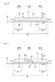
Fig. 6 conceptually shows a moving route of the winding position of theribbon rubber 20, in the forming step of the tread rubber shown inFig. 4 . As a matter of convenience for description, one side (a right side in the drawing) of the tire width direction WD in the tire meridian cross section is defined as WD1, and the other side is defined as WD2 (a left side in the drawing).
The ribbon rubber is wound from the start point S1 which is positioned closer to the center side than tread ends P1 and P2 in the tire meridian cross section toward the tire width direction WD1 side. Next, the ribbon rubber is folded back to a tire width direction WD2 side at the tread end P2 closer to the WD1 side, and is wound toward the tread end P1 on the WD2 side beyond the start point S1. Next, the ribbon rubber is folded back to the tire width direction WD1 side at the tread end P1 in the WD2 side, and is wound toward the end point E1 which is positioned closer to the center side than the tread end P2.
Further, as shown inFig. 6 , in the case that a range between 5 % and 25 % of the maximum width W of the tread rubber from the tread ends P1 and P2 toward the center side is defined as tread end vicinity portions Ar1 and Ar2, the ribbon rubber has the windingstart end S 1 and the winding terminal end E1 in the tread vicinity portions Ar1 and Ar2. A value or 5 % or more in the definition of the tread end vicinity portion means avoidance of the tapered tread end. Further, 25 % or less means avoidance of the tread center portion, however, 20 % or less is preferable for seeking out an improvement of the high-speed durability. - Specifically, the
ribbon rubber 20 is wound, as sequentially shown inFigs. 7A to 7C . In this case,Fig. 7 is drawn conceptually, and a cross sectional area ratio of each of the ribbon rubbers 20 with respect to thetread rubber 10 may be smaller. -
Fig. 7A corresponds to the stage inFig. 4B , and the winding position of the ribbon rubber moves to the tire width direction WD1 side (the right side) by defining the tread end vicinity portion Ar1 on the tire width direction WD2 side (the left side) among the pair of tread end vicinity portions Ar1 and Ar2 as the start point S1, and reaches the tread end P2 on the tire width direction WD1 side (the right side). Accordingly, a first layer L1 of theribbon rubber 20 is formed. -
Fig. 7B corresponds to the stage inFig. 4C , and the winding position of the ribbon rubber folds back to the tire width direction WD2 side (the left side) at the tread end P2 on the tire width direction WD1 side (the right side), goes over the start point S1, and reaches the tread end P1 on the tire width direction WD2 side (the left side). Accordingly, a second layer L2 of theribbon rubber 20 is formed. -
Fig. 7C corresponds to the stage inFig. 4D , and the winding position of the ribbon rubber folds back to the tire width direction WD1 side (the right side) at the tread end P1 in the tire width direction WD2 side (the left side), reaches the tread end vicinity portion Ar2 in the tire width direction WD1 side (the right side), and defines this as the end point E1. Accordingly, a third layer L3 of theribbon rubber 20 is formed. - As mentioned above, the pneumatic tire of the present embodiment provides a pneumatic tire T in which the
tread rubber 10 is formed by theribbon rubber 20 spirally wound around the tire rotating axis, wherein theribbon rubber 20 is wound toward the one side (WD1) in the tire width direction WD from the start point S1 which is positioned closer to the center side than the tread ends P1 and P2 in the tire meridian cross section, is next folded back to the other side (WD2) in the tire width direction WD at the tread end P2 on the one side (WD1), goes over the start point S1 so as to be wound toward the tread end P1 on the other side (WD2), is next folded back to the one side (WD1) in the tire width direction WD at the tread end P1 on the other side (WD2), and is wound toward the end point E1 which is positioned closer to the center side than the tread ends P1 and P2, and wherein theribbon rubber 20 has the winding start end S1 and the winding terminal end E1 in the tread end vicinity portions Ar1 and Ar2 avoiding the tread ends P1 and P2 and the tread center portion. - Further, the pneumatic tire of the present embodiment is produced by the following manufacturing method. In other words, the manufacturing method of the pneumatic tire of the present embodiment is a manufacturing method of a pneumatic tire including a tread rubber forming step of forming the tread rubber 10 by spirally winding the ribbon rubber 20 around the tire rotating axis, wherein the tread rubber forming step includes: a stage of winding the ribbon rubber 20 from the start point S1 which is positioned closer to the center side than the tread ends P1 and P2 in the tire meridian cross section toward the one side (WD1) in the tire width direction WD; next folding back the ribbon rubber to the other side (WD2) in the tire width direction WD at the tread end P2 on the one side (WD1), winding the ribbon rubber toward the tread end P1 on the other side (WD2) beyond the start point S1; next folding back the ribbon rubber to the one side (WD1) in the tire width direction WD at the tread end P1 on the other side (WD2); and winding the ribbon rubber toward the end point E1 which is positioned closer to the center side than the tread ends P1 and P2; and the ribbon rubber 20 has the winding start end S1 and the winding terminal end E1 in the tread vicinity portions Ar1 and Ar2 avoiding the tread ends P1 and P2 and the tread center portion.
- The tread end vicinity portions Ar1 and Ar2 mean a range between 5 and 25 % of a tread rubber maximum width W from the tread ends P1 and P2 toward the center side.
- According to the manufacturing method mentioned above, since the
tread rubber 10 can be formed by one winding process without disconnecting theribbon rubber 20 from the start point S1 to the end point E1, it is possible to improve the forming efficiency of thetread rubber 10.
Further, since the winding start end S1 and the winding terminal end E1 of theribbon rubber 20 are arranged at the tread end vicinity portions Ar1 and Ar2 avoiding the tread center portion, it is possible to reduce the influence of the centrifugal force and to improve the high-speed durability, in comparison with the case that the winding start end S1 and the winding terminal end E1 are arranged in the tread center portion.
In addition, since the winding start end S1 and the winding terminal end E1 are arranged at the tread end vicinity portions Ar1 and Ar2 avoiding the tread ends P1 and P2, it is possible to appropriately push theribbon rubber 20, and it is possible to suppress the defect. - Particularly, in the pneumatic tire of the present embodiment and the manufacturing method of the same, the
ribbon rubber 20 forms the first layer L1 which reaches the tread end P2 on the other side (WD1) in the tire width direction by defining a tread end vicinity portion Ar1 on the one side (WD2) in the tire width direction WD among the paired tread end vicinity portions Ar1 and Ar2 as the start point S1, next forms the second layer L2 which reaches the tread end P1 on the one side (WD2) beyond the start point S1 by folding back to the one side (WD2) in the tire width direction at the tread end P2 on the other side (WD1) in the tire width direction, and next forms the third layer L3 which defines the tread end vicinity portion Ar2 on the other side (WD1) in the tire width direction as the end point E1 by folding back to the other side (WD1) in the tire width direction at the tread end P1 on the one side (WD2). - According to the structure mentioned above, since it is possible to secure the thickness of the
tread rubber 10 without narrowing the winding pitch P20 of theribbon rubber 20 as well as raising theribbon rubber 20, it is possible to improve both the securing of the thickness and the winding controllability of the ribbon rubber. Particularly, it is useful for forming the tire which requires a greater thickness such as a truck and a bus. - (1) The present invention is not limited to the present embodiment as long as the
ribbon rubber 20 is wound without being disconnected on the way and the winding start end and terminal end are at the tread end vicinity portion.
For example, the winding way shown inFig. 8 can be envisaged. In other words, the winding position of theribbon rubber 20 reaches the tread end P1 on the one side (WD2) in the tire width direction by defining the tread end vicinity portion Ar1 on the one side (WD2) as a start point S2, folds back to the other side (WD1) in the tire width direction at the tread end P1 so as to reach the tread end P2 on the other side (WD1) in the tire width direction beyond the start point S2, folds back to the one side (WD2) in the tire width direction at the tread end P2, reaches the tread end vicinity portion Ar2 on the other side (WD1), and defines the tread end vicinity portion Ar2 as a terminal end E2.
In this example, the winding terminal end E2 of theribbon rubber 20 is arranged at the forming position of themain groove 15 which extends in the tire peripheral direction, as shown inFig. 8 . In the forming position of themain groove 15, since the thickness of the rubber is reduced, and the heat generation at the time of the high-speed rotation is suppressed in conjunction therewith, it is possible to suppress failures which are caused by such a heat generation, and it is possible to further improve the high-speed durability. - (2) As a different winding method from the above method, a winding start end S2 and a winding terminal end E3 of the
ribbon rubber 20 may be arranged only at the one tread end vicinity portion Ar1 among the paired tread end vicinity portions Ar1 and Ar2, as shown inFig. 9 . - (3) As a different winding method from the above method, there can be listed up a structure in which the tread rubber has a three-layer structure portion D3 at a position which is closer to the center side than the tread ends P1 and P2, by folding back the ribbon rubber which is wound toward the one side (WD1) in the tire width direction at a position P3, winding toward the other side (WD2) in the tire width direction, thereafter folding back again at a position P4, and winding toward the one side (WD1) in the width direction, as shown in
Fig. 10 .
According to the structure mentioned above, it is possible to easily secure the thickness of thetread rubber 10 without narrowing the winding pitch P20 of theribbon rubber 20 as well as raising theribbon rubber 20. In an example shown inFig. 11 , a plurality of three-layer structure portions D3 are formed. - (4) As a different winding method from the above method, a winding method shown in
Fig. 12 can be listed up. In other words, the ribbon rubber is wound toward the other side (WD1) in the tire width direction by defining the tread vicinity portion Ar1 on the one side (WD2) as the start point S2.
Next, the ribbon rubber is folded back at the position P3 so as to be wound toward the one side (WD2) in the tire width direction beyond the start point S2, is folded to the other side (WD1) in the tire width direction at the tread end P1 on the one side (WD2), and is wound toward the tread end P2 on the other side (WD1) beyond the start point S2. Next, the ribbon rubber is folded back at the tread end P2 on the other side (WD1), and is wound to the terminal end E2 which is positioned closer to the center side than the tread end P2.
According to the structure mentioned above, since it is possible to keep the tread end P2 and the winding terminal end E2 away from each other by folding back the winding terminal end E2, it is possible to further reduce the problem caused by the movement of the winding terminal end E2 closer to the tread end P2. As one example of the problem, for example, there can be listed up a defect caused by a short pressing of the ribbon rubber by the following roller (stitcher), - Further, it is preferable that the winding start end S1 and the winding terminal end E1 are kept away at 180° in the tire peripheral direction. In other words, since a radial force variation (RFV) is improved and a ground surface pressure distribution on a periphery becomes uniform as long as the winding start end S1 and the winding terminal end E1 are in a positional relationship which is symmetrical around the tire rotating axis, it is possible to improve the high-speed durability.
- A description will be given below of examples which effectively show the structure and the effect of the present invention. In this case, the high-speed durability was evaluated by using a test tire having a tire size 215/45R17. The high-speed durability was tested on the basis of a condition about tire of a speed mark H (210 km/h) which was defined as load/speed performance test procedure by a
supplementary provision 7 of Regulation No. 30 of Economic Commission for Europe (Regulation No. 30 Uniform Provisions Concerning the Approval of Pneumatic Tires for Motor Vehicles and Their Trailers).
The high-speed durability was evaluated by traveling at a high speed by a drum tester until the tire broke down, according to a method of increasing the traveling speed at 10 km/h per ten minutes. Therefore, the higher speed indicates the more excellent high-speed durability. - The tire was produced by arranging the winding start of the ribbon rubber to the center portion in the tire width direction, winding the ribbon rubber like a infinity symbol shape, and arranging the winding terminal end at the center portion (the equator portion) in the tire width direction (refer to
JP-A-2006-130880 - The tread rubber was formed by winding the ribbon rubber via the route shown in
Fig. 6 . The winding start end S1 and the winding terminal end E1 of theribbon rubber 20 were arranged respectively at positions which were 12.5 % of the maximum width W of the tread rubber from the tread ends P1 and P2 toward the center side. The same structures as in the Comparative Example were applied with the exception of the above. - The tread rubber was formed by winding the ribbon rubber via the route shown in
Fig. 8 . The winding start end 52 and the winding terminal end E2 of theribbon rubber 20 were arranged respectively at positions which were 20 % of the maximum width W of the tread rubber from the tread ends P1 and P2 toward the center side. The same structures as in the Comparative Example were applied with the exception of the above. - The tread rubber was formed by winding the ribbon rubber via the route shown in
Fig. 9 . The winding start end S2 and the winding terminal end E3 of theribbon rubber 20 were arranged respectively at positions which were 24. % of the maximum width W of the tread rubber from the tread end P1 toward the center side. The same structures as in the Comparative Example were applied with the exception of the above. - The tread rubber was formed by winding the ribbon rubber via the route shown in
Fig. 10 . The winding start end S2 and the winding terminal end E2 of theribbon rubber 20 were arranged respectively at positions which were 23.2 % of the maximum width W of the tread rubber from the tread ends P1 and P2 toward the center side. The same structures as in the Comparative Example were applied with the exception of the above. - The tread rubber was formed by winding the ribbon rubber via the route shown in
Fig. 12 . The winding start end S2 and the winding terminal end E2 of theribbon rubber 20 were arranged respectively at positions which were 20 % the maximum width W of the tread rubber from the tread ends P1 and P2 toward the center side. The same structures as in the Comparative Example were applied with the exception of the above. -
Table 1 Comparative Example Example 1 Example 2 Example 3 Example 4 Example 5 High-speed durability 280 km/h 310km/h 310 km/h 300 km/h 290 km/h 300 km/h - In the Comparative Example, the failure was generated at 280 km/h, however, the speeds at which the failure was generated were higher in all the Examples 1 to 5 than in the Comparative Example, Accordingly, it is known that the high-speed durability is improved. In this case, it can be thought that the Example 4 is lower in the high-speed durability in comparison with the Examples 1 to 3 since the fold-back end of the
ribbon rubber 20 exists at the tread intermediate portion between the paired tread end vicinity portions Ar1 and Ar2.
Therefore, in the light of pursuit of the high-speed durability, it is thought to be preferable that the tread intermediate portion (including the tire equator) does not have any fold-back end. - It is possible to apply the structure employed in each of the embodiments to the other optional embodiment. The particular structure of each of the portions is not limited to the embodiments mentioned above, but can be variously modified within a range which does not deviate from the scope of the present invention.
-
- 1 =
- portion
- 1a =
- bead core
- 1b =
- bead filler
- 2 =
- side wall portion
- 3 =
- portion
- 4 =
- rim strip rubber
- 5 =
- inner liner rubber
- 6 =
- belt layer
- 7 =
- layer
- 8 =
- belt reinforcing layer
- 9 =
- side wall rubber
- 10 =
- rubber
- 11 =
- portion
- 12 =
- cap portion
- 15 =
- main groove
- 20 =
- ribbon rubber
- 30 =
- ribbon rubber forming device
- 31 =
- rotation support body
- 31a =
- axis
- 32 =
- control device
- T =
- tire
- S1 =
- start point
- E1 =
- end point
- P1, P2 =
- tread ends
- Ar1, Ar2 =
- vicinity portions
- WD =
- tire width direction
Claims (8)
- A pneumatic tire comprising:- a rubber (10), the rubber (10) being formed by a ribbon rubber (20) which is spirally wound around a tire rotating axis,- wherein the ribbon rubber (20) is wound from a start point (S1) which is positioned closer to a center side than tread ends (P1, P2) toward one side in a tire width direction (WD) in a tire meridian cross section, is next folded back to the other side in the tire width direction (WD) at the tread end on the one side, is wound toward the tread end on the other side beyond the start point (Sl), is next folded back to the one side in the tire width direction (WD) at the tread end on the other side, and is wound toward a terminal end (E1) which is positioned closer to the center side than the tread ends (P1, P2), and- wherein the ribbon rubber (20) has a winding start end and a winding terminal end in the vicinity of the tread ends avoiding the tread ends and the tread center portion.
- The pneumatic tire according to claim 1,
wherein the winding terminal end (E1) is arranged at a position at which a main groove (15) extending in a tire peripheral direction is formed. - The pneumatic tire according to claim 1 or 2,
wherein the tread rubber (10) has a three-layer structure portion in which the ribbon rubber (20) wound toward the one side in the tire width direction (WD) is folded back, is wound toward the other side in the tire width direction (WD), is thereafter folded back again and is wound toward the one side in the tire width direction (WD), at the position closer to the center side the tread ends (P1, P2). - The pneumatic tire according to any one of claim 1 to 3,
wherein the ribbon rubber (20) forms a first layer which has the vicinity portion of the tread end on the one side in the tire width direction (WD) as a start point (S1), among the vicinity portions of the pair treads to the tread end on the other side in the tire width direction (WD), next forms a second layer which is folded back to the one side in the tire width direction (WD) at the tread end on the other side in the tire width direction and reaches the tread end on the one side beyond the start point (S1), and next forms a third layer which is folded back to the other side in the tire width direction (WD) at the tread end on the one side and has the vicinity portion of the tread end on the other side in the tire width direction (WD) as a terminal end (E1). - A manufacturing method of a pneumatic tire, comprising:- a tread rubber (10) forming step of forming a tread rubber (10) by spirally winding a ribbon rubber (20) around a tire rotating axis,- wherein the tread rubber forming step comprises a stage of winding the ribbon rubber (20) from a start point (S1) which is positioned closer to a center side than tread ends (P1, P2) in a tire meridian cross section toward one side in a tire width direction (WD), next folding back the ribbon rubber (20) to the other side in the tire width direction (WD) at the tread end on the one side, winding the ribbon rubber (20) toward the tread end on the other side beyond the start point (S1), next folding back the ribbon rubber (20) to the one side in the tire width direction (WD) at the tread end on the other side, and winding the ribbon rubber (20) toward a terminal end (E1) which is positioned closer to the center side than the tread ends (P1, P2), and- wherein the ribbon, rubber (20) has a winding start end (S1) and a winding terminal end (E1) in the vicinity portion of the tread end avoiding the tread end and the tread center portion.
- The manufacturing method according to claim 5,
wherein the winding terminal end (E1) is arranged at the forming position of the main groove (15) extending in the tire peripheral direction. - The manufacturing method according to claim 5 or 6,
wherein the three-layer structure portion is formed by folding back the ribbon rubber (20) which is wound toward the one side in the tire width direction (WD), at the position which is closer to the center side than the tread ends (P1, P2), winding the ribbon rubber (20) toward the other side in the tire width direction (WD), and thereafter folding back the ribbon rubber (20) again so as to wind toward the one side in the tire width direction (WD). - The manufacturing method according to any one of claim 5 to 7, wherein a first layer is formed by moving the winding position of the ribbon rubber (20) to the tread end on the other side in the tire width direction (WD) from the start point (S1) of the vicinity portion of the tread end on the one side in the tire width direction (WD), among the vicinity portions of the pair treads, a second layer is next formed by folding back the winding position of the ribbon rubber (20) to the one side in the tire width direction (WD) at the tread end on the other side in the tire width direction (WD) and moving to the tread end on the one side beyond the start point (S1), and a third layer is next formed by folding back the winding position of the ribbon rubber (20) to the other side in the tire width direction at the tread end on the one side and defining the vicinity portion of the tread end on the other side in the tire width direction (WD) as a terminal end (E1).
Applications Claiming Priority (2)
| Application Number | Priority Date | Filing Date | Title |
|---|---|---|---|
| JP2011277608 | 2011-12-19 | ||
| JP2012200587A JP6061577B2 (en) | 2011-12-19 | 2012-09-12 | Pneumatic tire and manufacturing method thereof |
Publications (2)
| Publication Number | Publication Date |
|---|---|
| EP2607065A1 true EP2607065A1 (en) | 2013-06-26 |
| EP2607065B1 EP2607065B1 (en) | 2016-04-27 |
Family
ID=47325946
Family Applications (1)
| Application Number | Title | Priority Date | Filing Date |
|---|---|---|---|
| EP12196688.1A Not-in-force EP2607065B1 (en) | 2011-12-19 | 2012-12-12 | Pneumatic tire and manufacturing method of the same |
Country Status (4)
| Country | Link |
|---|---|
| US (1) | US20130340904A1 (en) |
| EP (1) | EP2607065B1 (en) |
| JP (1) | JP6061577B2 (en) |
| CN (2) | CN106114067B (en) |
Families Citing this family (6)
| Publication number | Priority date | Publication date | Assignee | Title |
|---|---|---|---|---|
| JP6117082B2 (en) * | 2013-11-21 | 2017-04-19 | 東洋ゴム工業株式会社 | Method and device for applying strip rubber |
| JP6235990B2 (en) | 2014-10-17 | 2017-11-22 | 住友ゴム工業株式会社 | Sealant tire |
| WO2016060246A1 (en) | 2014-10-17 | 2016-04-21 | 住友ゴム工業株式会社 | Rubber composition for pneumatic tires |
| CN106715160B (en) | 2014-10-17 | 2019-09-03 | 住友橡胶工业株式会社 | Pneumatic tire and its manufacturing method |
| JP7494482B2 (en) * | 2020-02-18 | 2024-06-04 | 住友ゴム工業株式会社 | Tread rubber forming method and tread rubber forming device |
| CN111267553B (en) * | 2020-03-24 | 2022-03-11 | 江苏通用科技股份有限公司 | Multi-layer type rubber tread structure |
Citations (7)
| Publication number | Priority date | Publication date | Assignee | Title |
|---|---|---|---|---|
| DE3916271A1 (en) * | 1988-09-02 | 1990-03-15 | Yokohama Rubber Co Ltd | METHOD FOR WRAPPING A REINFORCING LAYER OF A COMPRESSED AIR RADIAL TIRE |
| EP1020284A2 (en) * | 1999-01-12 | 2000-07-19 | Sumitomo Rubber Industries Ltd. | Method of manufacturing rubber tyre component |
| US6510881B1 (en) * | 1999-06-17 | 2003-01-28 | The Yokohama Rubber Co., Ltd. | Pneumatic radial tire and method of manufacturing the same |
| EP1629964A2 (en) * | 2004-08-26 | 2006-03-01 | Sumitomo Rubber Industries, Ltd. | Method for manufacturing a pneumatic tire and a pneumatic tire obtained thereby |
| JP2006062196A (en) * | 2004-08-26 | 2006-03-09 | Sumitomo Rubber Ind Ltd | Manufacturing method of rubber member for tire and pneumatic tire |
| EP1803544A1 (en) * | 2005-12-29 | 2007-07-04 | Sumitomo Rubber Industries Ltd. | Pneumatic tire and method for making uncured rubber tire component |
| DE102008013769A1 (en) * | 2007-05-18 | 2008-11-20 | Sumitomo Rubber Industries, Ltd., Kobe-shi | Method for producing a pneumatic tire |
Family Cites Families (14)
| Publication number | Priority date | Publication date | Assignee | Title |
|---|---|---|---|---|
| US3177918A (en) * | 1959-12-24 | 1965-04-13 | Voit Rubber Corp | Method of building a tread on pneumatic tires |
| JPH0655562B2 (en) * | 1986-04-22 | 1994-07-27 | 株式会社ブリヂストン | Pneumatic tire |
| EP0524702B1 (en) * | 1987-06-18 | 1995-08-23 | Sumitomo Rubber Industries Limited | Pneumatic radial tyre |
| JP3236046B2 (en) * | 1991-12-27 | 2001-12-04 | 横浜ゴム株式会社 | How to wind rubber strip |
| DE4212295B4 (en) * | 1992-04-11 | 2005-02-17 | Uniroyal Englebert Reifen Gmbh | Vehicle tires |
| JP2001038822A (en) * | 1999-07-30 | 2001-02-13 | Bridgestone Corp | Large pneumatic tire and manufacturing method thereof |
| JP4039895B2 (en) * | 2002-06-24 | 2008-01-30 | 横浜ゴム株式会社 | Method for forming tire tread component and pneumatic tire |
| JP4437888B2 (en) * | 2003-01-24 | 2010-03-24 | 株式会社ブリヂストン | Pneumatic tire |
| JP4585307B2 (en) * | 2004-12-24 | 2010-11-24 | 住友ゴム工業株式会社 | Method for manufacturing motorcycle tire |
| DE112006004011T5 (en) * | 2006-08-31 | 2009-07-23 | Toyo Tire & Rubber Co., Ltd. | A method of manufacturing a pneumatic tire and pneumatic tires |
| JP4392444B2 (en) * | 2007-11-21 | 2010-01-06 | 住友ゴム工業株式会社 | Pneumatic tire and manufacturing method thereof |
| RU2471643C2 (en) * | 2007-11-21 | 2013-01-10 | Сумитомо Раббер Индастриз, Лтд. | Pneumatic tire and method of its producing |
| JP4575979B2 (en) * | 2008-11-11 | 2010-11-04 | 住友ゴム工業株式会社 | Pneumatic tire and manufacturing method thereof |
| JP5456074B2 (en) * | 2011-09-21 | 2014-03-26 | 東洋ゴム工業株式会社 | Pneumatic tire manufacturing method |
-
2012
- 2012-09-12 JP JP2012200587A patent/JP6061577B2/en active Active
- 2012-11-15 CN CN201610546721.1A patent/CN106114067B/en not_active Expired - Fee Related
- 2012-11-15 CN CN201210460314.0A patent/CN103158441B/en not_active Expired - Fee Related
- 2012-11-27 US US13/685,846 patent/US20130340904A1/en not_active Abandoned
- 2012-12-12 EP EP12196688.1A patent/EP2607065B1/en not_active Not-in-force
Patent Citations (7)
| Publication number | Priority date | Publication date | Assignee | Title |
|---|---|---|---|---|
| DE3916271A1 (en) * | 1988-09-02 | 1990-03-15 | Yokohama Rubber Co Ltd | METHOD FOR WRAPPING A REINFORCING LAYER OF A COMPRESSED AIR RADIAL TIRE |
| EP1020284A2 (en) * | 1999-01-12 | 2000-07-19 | Sumitomo Rubber Industries Ltd. | Method of manufacturing rubber tyre component |
| US6510881B1 (en) * | 1999-06-17 | 2003-01-28 | The Yokohama Rubber Co., Ltd. | Pneumatic radial tire and method of manufacturing the same |
| EP1629964A2 (en) * | 2004-08-26 | 2006-03-01 | Sumitomo Rubber Industries, Ltd. | Method for manufacturing a pneumatic tire and a pneumatic tire obtained thereby |
| JP2006062196A (en) * | 2004-08-26 | 2006-03-09 | Sumitomo Rubber Ind Ltd | Manufacturing method of rubber member for tire and pneumatic tire |
| EP1803544A1 (en) * | 2005-12-29 | 2007-07-04 | Sumitomo Rubber Industries Ltd. | Pneumatic tire and method for making uncured rubber tire component |
| DE102008013769A1 (en) * | 2007-05-18 | 2008-11-20 | Sumitomo Rubber Industries, Ltd., Kobe-shi | Method for producing a pneumatic tire |
Also Published As
| Publication number | Publication date |
|---|---|
| CN103158441A (en) | 2013-06-19 |
| CN106114067A (en) | 2016-11-16 |
| US20130340904A1 (en) | 2013-12-26 |
| JP2013147243A (en) | 2013-08-01 |
| EP2607065B1 (en) | 2016-04-27 |
| CN106114067B (en) | 2018-06-22 |
| CN103158441B (en) | 2016-08-10 |
| JP6061577B2 (en) | 2017-01-18 |
Similar Documents
| Publication | Publication Date | Title |
|---|---|---|
| EP2481560B1 (en) | Method for manufacturing pneumatic tire | |
| CN1962291B (en) | Pneumatic tire and method for producing the same, and cushion rubber for the tire | |
| EP2607065B1 (en) | Pneumatic tire and manufacturing method of the same | |
| EP2308694B1 (en) | Pneumatic tire | |
| EP2572902A1 (en) | Pneumatic tire and manufacturing method of the same | |
| CN109551797B (en) | Pneumatic tire and method of making the same | |
| JP4585307B2 (en) | Method for manufacturing motorcycle tire | |
| EP2974891B1 (en) | Pneumatic tire | |
| US20140138006A1 (en) | Pneumatic tire and manufacturing method of the same | |
| US10894376B2 (en) | Pneumatic tire and manufacturing method therefor | |
| JP6043553B2 (en) | Pneumatic tire | |
| JP2010285106A (en) | Pneumatic tire and manufacturing method thereof | |
| JP6084444B2 (en) | Pneumatic tire and manufacturing method thereof | |
| JP2013079050A (en) | Pneumatic tire | |
| JP6025463B2 (en) | Pneumatic tire | |
| JP6030623B2 (en) | Pneumatic tire | |
| EP1800845B1 (en) | Pneumatic tire and method of manufacturing the same | |
| US20190248087A1 (en) | Tire manufacturing method and tire | |
| US20070044884A1 (en) | Pneumatic tire and producing method of pneumatic tire | |
| US20090008012A1 (en) | Pneumatic tire, arrangement structure and manufacturing method of the same | |
| JP6077281B2 (en) | Pneumatic tire and manufacturing method thereof | |
| KR101982844B1 (en) | Pneumatic tire | |
| JP2008030660A (en) | Pneumatic tire and manufacturing method thereof | |
| JP2022045556A (en) | Tire, manufacturing method for tire, and tire design method | |
| JP2000094910A (en) | Pneumatic tire and method for manufacturing pneumatic tire |
Legal Events
| Date | Code | Title | Description |
|---|---|---|---|
| AK | Designated contracting states |
Kind code of ref document: A1 Designated state(s): AL AT BE BG CH CY CZ DE DK EE ES FI FR GB GR HR HU IE IS IT LI LT LU LV MC MK MT NL NO PL PT RO RS SE SI SK SM TR |
|
| AX | Request for extension of the european patent |
Extension state: BA ME |
|
| PUAI | Public reference made under article 153(3) epc to a published international application that has entered the european phase |
Free format text: ORIGINAL CODE: 0009012 |
|
| 17P | Request for examination filed |
Effective date: 20131220 |
|
| RBV | Designated contracting states (corrected) |
Designated state(s): AL AT BE BG CH CY CZ DE DK EE ES FI FR GB GR HR HU IE IS IT LI LT LU LV MC MK MT NL NO PL PT RO RS SE SI SK SM TR |
|
| 17Q | First examination report despatched |
Effective date: 20140818 |
|
| GRAP | Despatch of communication of intention to grant a patent |
Free format text: ORIGINAL CODE: EPIDOSNIGR1 |
|
| INTG | Intention to grant announced |
Effective date: 20151022 |
|
| GRAS | Grant fee paid |
Free format text: ORIGINAL CODE: EPIDOSNIGR3 |
|
| GRAA | (expected) grant |
Free format text: ORIGINAL CODE: 0009210 |
|
| AK | Designated contracting states |
Kind code of ref document: B1 Designated state(s): AL AT BE BG CH CY CZ DE DK EE ES FI FR GB GR HR HU IE IS IT LI LT LU LV MC MK MT NL NO PL PT RO RS SE SI SK SM TR |
|
| REG | Reference to a national code |
Ref country code: GB Ref legal event code: FG4D |
|
| REG | Reference to a national code |
Ref country code: CH Ref legal event code: EP |
|
| REG | Reference to a national code |
Ref country code: AT Ref legal event code: REF Ref document number: 794252 Country of ref document: AT Kind code of ref document: T Effective date: 20160515 |
|
| REG | Reference to a national code |
Ref country code: IE Ref legal event code: FG4D |
|
| REG | Reference to a national code |
Ref country code: DE Ref legal event code: R096 Ref document number: 602012017607 Country of ref document: DE |
|
| REG | Reference to a national code |
Ref country code: LT Ref legal event code: MG4D |
|
| REG | Reference to a national code |
Ref country code: NL Ref legal event code: MP Effective date: 20160427 |
|
| REG | Reference to a national code |
Ref country code: AT Ref legal event code: MK05 Ref document number: 794252 Country of ref document: AT Kind code of ref document: T Effective date: 20160427 |
|
| PG25 | Lapsed in a contracting state [announced via postgrant information from national office to epo] |
Ref country code: NL Free format text: LAPSE BECAUSE OF FAILURE TO SUBMIT A TRANSLATION OF THE DESCRIPTION OR TO PAY THE FEE WITHIN THE PRESCRIBED TIME-LIMIT Effective date: 20160427 |
|
| PG25 | Lapsed in a contracting state [announced via postgrant information from national office to epo] |
Ref country code: FI Free format text: LAPSE BECAUSE OF FAILURE TO SUBMIT A TRANSLATION OF THE DESCRIPTION OR TO PAY THE FEE WITHIN THE PRESCRIBED TIME-LIMIT Effective date: 20160427 Ref country code: NO Free format text: LAPSE BECAUSE OF FAILURE TO SUBMIT A TRANSLATION OF THE DESCRIPTION OR TO PAY THE FEE WITHIN THE PRESCRIBED TIME-LIMIT Effective date: 20160727 Ref country code: PL Free format text: LAPSE BECAUSE OF FAILURE TO SUBMIT A TRANSLATION OF THE DESCRIPTION OR TO PAY THE FEE WITHIN THE PRESCRIBED TIME-LIMIT Effective date: 20160427 Ref country code: LT Free format text: LAPSE BECAUSE OF FAILURE TO SUBMIT A TRANSLATION OF THE DESCRIPTION OR TO PAY THE FEE WITHIN THE PRESCRIBED TIME-LIMIT Effective date: 20160427 |
|
| PG25 | Lapsed in a contracting state [announced via postgrant information from national office to epo] |
Ref country code: SE Free format text: LAPSE BECAUSE OF FAILURE TO SUBMIT A TRANSLATION OF THE DESCRIPTION OR TO PAY THE FEE WITHIN THE PRESCRIBED TIME-LIMIT Effective date: 20160427 Ref country code: GR Free format text: LAPSE BECAUSE OF FAILURE TO SUBMIT A TRANSLATION OF THE DESCRIPTION OR TO PAY THE FEE WITHIN THE PRESCRIBED TIME-LIMIT Effective date: 20160728 Ref country code: RS Free format text: LAPSE BECAUSE OF FAILURE TO SUBMIT A TRANSLATION OF THE DESCRIPTION OR TO PAY THE FEE WITHIN THE PRESCRIBED TIME-LIMIT Effective date: 20160427 Ref country code: AT Free format text: LAPSE BECAUSE OF FAILURE TO SUBMIT A TRANSLATION OF THE DESCRIPTION OR TO PAY THE FEE WITHIN THE PRESCRIBED TIME-LIMIT Effective date: 20160427 Ref country code: HR Free format text: LAPSE BECAUSE OF FAILURE TO SUBMIT A TRANSLATION OF THE DESCRIPTION OR TO PAY THE FEE WITHIN THE PRESCRIBED TIME-LIMIT Effective date: 20160427 Ref country code: LV Free format text: LAPSE BECAUSE OF FAILURE TO SUBMIT A TRANSLATION OF THE DESCRIPTION OR TO PAY THE FEE WITHIN THE PRESCRIBED TIME-LIMIT Effective date: 20160427 Ref country code: PT Free format text: LAPSE BECAUSE OF FAILURE TO SUBMIT A TRANSLATION OF THE DESCRIPTION OR TO PAY THE FEE WITHIN THE PRESCRIBED TIME-LIMIT Effective date: 20160829 Ref country code: ES Free format text: LAPSE BECAUSE OF FAILURE TO SUBMIT A TRANSLATION OF THE DESCRIPTION OR TO PAY THE FEE WITHIN THE PRESCRIBED TIME-LIMIT Effective date: 20160427 |
|
| PG25 | Lapsed in a contracting state [announced via postgrant information from national office to epo] |
Ref country code: IT Free format text: LAPSE BECAUSE OF FAILURE TO SUBMIT A TRANSLATION OF THE DESCRIPTION OR TO PAY THE FEE WITHIN THE PRESCRIBED TIME-LIMIT Effective date: 20160427 Ref country code: BE Free format text: LAPSE BECAUSE OF FAILURE TO SUBMIT A TRANSLATION OF THE DESCRIPTION OR TO PAY THE FEE WITHIN THE PRESCRIBED TIME-LIMIT Effective date: 20160427 |
|
| REG | Reference to a national code |
Ref country code: DE Ref legal event code: R097 Ref document number: 602012017607 Country of ref document: DE |
|
| PG25 | Lapsed in a contracting state [announced via postgrant information from national office to epo] |
Ref country code: RO Free format text: LAPSE BECAUSE OF FAILURE TO SUBMIT A TRANSLATION OF THE DESCRIPTION OR TO PAY THE FEE WITHIN THE PRESCRIBED TIME-LIMIT Effective date: 20160427 Ref country code: DK Free format text: LAPSE BECAUSE OF FAILURE TO SUBMIT A TRANSLATION OF THE DESCRIPTION OR TO PAY THE FEE WITHIN THE PRESCRIBED TIME-LIMIT Effective date: 20160427 Ref country code: SK Free format text: LAPSE BECAUSE OF FAILURE TO SUBMIT A TRANSLATION OF THE DESCRIPTION OR TO PAY THE FEE WITHIN THE PRESCRIBED TIME-LIMIT Effective date: 20160427 Ref country code: CZ Free format text: LAPSE BECAUSE OF FAILURE TO SUBMIT A TRANSLATION OF THE DESCRIPTION OR TO PAY THE FEE WITHIN THE PRESCRIBED TIME-LIMIT Effective date: 20160427 Ref country code: EE Free format text: LAPSE BECAUSE OF FAILURE TO SUBMIT A TRANSLATION OF THE DESCRIPTION OR TO PAY THE FEE WITHIN THE PRESCRIBED TIME-LIMIT Effective date: 20160427 |
|
| PG25 | Lapsed in a contracting state [announced via postgrant information from national office to epo] |
Ref country code: SM Free format text: LAPSE BECAUSE OF FAILURE TO SUBMIT A TRANSLATION OF THE DESCRIPTION OR TO PAY THE FEE WITHIN THE PRESCRIBED TIME-LIMIT Effective date: 20160427 |
|
| PLBE | No opposition filed within time limit |
Free format text: ORIGINAL CODE: 0009261 |
|
| STAA | Information on the status of an ep patent application or granted ep patent |
Free format text: STATUS: NO OPPOSITION FILED WITHIN TIME LIMIT |
|
| 26N | No opposition filed |
Effective date: 20170130 |
|
| PG25 | Lapsed in a contracting state [announced via postgrant information from national office to epo] |
Ref country code: SI Free format text: LAPSE BECAUSE OF FAILURE TO SUBMIT A TRANSLATION OF THE DESCRIPTION OR TO PAY THE FEE WITHIN THE PRESCRIBED TIME-LIMIT Effective date: 20160427 |
|
| REG | Reference to a national code |
Ref country code: CH Ref legal event code: PL |
|
| GBPC | Gb: european patent ceased through non-payment of renewal fee |
Effective date: 20161212 |
|
| PG25 | Lapsed in a contracting state [announced via postgrant information from national office to epo] |
Ref country code: MC Free format text: LAPSE BECAUSE OF FAILURE TO SUBMIT A TRANSLATION OF THE DESCRIPTION OR TO PAY THE FEE WITHIN THE PRESCRIBED TIME-LIMIT Effective date: 20160427 |
|
| REG | Reference to a national code |
Ref country code: FR Ref legal event code: ST Effective date: 20170831 |
|
| REG | Reference to a national code |
Ref country code: IE Ref legal event code: MM4A |
|
| PG25 | Lapsed in a contracting state [announced via postgrant information from national office to epo] |
Ref country code: LI Free format text: LAPSE BECAUSE OF NON-PAYMENT OF DUE FEES Effective date: 20161231 Ref country code: FR Free format text: LAPSE BECAUSE OF NON-PAYMENT OF DUE FEES Effective date: 20170102 Ref country code: LU Free format text: LAPSE BECAUSE OF NON-PAYMENT OF DUE FEES Effective date: 20161212 Ref country code: CH Free format text: LAPSE BECAUSE OF NON-PAYMENT OF DUE FEES Effective date: 20161231 |
|
| PG25 | Lapsed in a contracting state [announced via postgrant information from national office to epo] |
Ref country code: IE Free format text: LAPSE BECAUSE OF NON-PAYMENT OF DUE FEES Effective date: 20161212 Ref country code: GB Free format text: LAPSE BECAUSE OF NON-PAYMENT OF DUE FEES Effective date: 20161212 |
|
| PG25 | Lapsed in a contracting state [announced via postgrant information from national office to epo] |
Ref country code: CY Free format text: LAPSE BECAUSE OF FAILURE TO SUBMIT A TRANSLATION OF THE DESCRIPTION OR TO PAY THE FEE WITHIN THE PRESCRIBED TIME-LIMIT Effective date: 20160427 Ref country code: HU Free format text: LAPSE BECAUSE OF FAILURE TO SUBMIT A TRANSLATION OF THE DESCRIPTION OR TO PAY THE FEE WITHIN THE PRESCRIBED TIME-LIMIT; INVALID AB INITIO Effective date: 20121212 |
|
| PG25 | Lapsed in a contracting state [announced via postgrant information from national office to epo] |
Ref country code: TR Free format text: LAPSE BECAUSE OF FAILURE TO SUBMIT A TRANSLATION OF THE DESCRIPTION OR TO PAY THE FEE WITHIN THE PRESCRIBED TIME-LIMIT Effective date: 20160427 Ref country code: IS Free format text: LAPSE BECAUSE OF FAILURE TO SUBMIT A TRANSLATION OF THE DESCRIPTION OR TO PAY THE FEE WITHIN THE PRESCRIBED TIME-LIMIT Effective date: 20160427 Ref country code: MK Free format text: LAPSE BECAUSE OF FAILURE TO SUBMIT A TRANSLATION OF THE DESCRIPTION OR TO PAY THE FEE WITHIN THE PRESCRIBED TIME-LIMIT Effective date: 20160427 |
|
| PG25 | Lapsed in a contracting state [announced via postgrant information from national office to epo] |
Ref country code: BG Free format text: LAPSE BECAUSE OF FAILURE TO SUBMIT A TRANSLATION OF THE DESCRIPTION OR TO PAY THE FEE WITHIN THE PRESCRIBED TIME-LIMIT Effective date: 20160427 |
|
| PG25 | Lapsed in a contracting state [announced via postgrant information from national office to epo] |
Ref country code: MT Free format text: LAPSE BECAUSE OF NON-PAYMENT OF DUE FEES Effective date: 20161212 |
|
| PG25 | Lapsed in a contracting state [announced via postgrant information from national office to epo] |
Ref country code: AL Free format text: LAPSE BECAUSE OF FAILURE TO SUBMIT A TRANSLATION OF THE DESCRIPTION OR TO PAY THE FEE WITHIN THE PRESCRIBED TIME-LIMIT Effective date: 20160427 |
|
| PGFP | Annual fee paid to national office [announced via postgrant information from national office to epo] |
Ref country code: DE Payment date: 20221102 Year of fee payment: 11 |
|
| REG | Reference to a national code |
Ref country code: DE Ref legal event code: R119 Ref document number: 602012017607 Country of ref document: DE |
|
| PG25 | Lapsed in a contracting state [announced via postgrant information from national office to epo] |
Ref country code: DE Free format text: LAPSE BECAUSE OF NON-PAYMENT OF DUE FEES Effective date: 20240702 |
|
| PG25 | Lapsed in a contracting state [announced via postgrant information from national office to epo] |
Ref country code: DE Free format text: LAPSE BECAUSE OF NON-PAYMENT OF DUE FEES Effective date: 20240702 |