EP2606753A1 - A unit for feeding a rising flow of cut tobacco of a twin-rod cigarette making machine - Google Patents
A unit for feeding a rising flow of cut tobacco of a twin-rod cigarette making machine Download PDFInfo
- Publication number
- EP2606753A1 EP2606753A1 EP12197156.8A EP12197156A EP2606753A1 EP 2606753 A1 EP2606753 A1 EP 2606753A1 EP 12197156 A EP12197156 A EP 12197156A EP 2606753 A1 EP2606753 A1 EP 2606753A1
- Authority
- EP
- European Patent Office
- Prior art keywords
- section
- channel
- tobacco
- flow
- cross
- Prior art date
- Legal status (The legal status is an assumption and is not a legal conclusion. Google has not performed a legal analysis and makes no representation as to the accuracy of the status listed.)
- Granted
Links
- 241000208125 Nicotiana Species 0.000 title claims abstract description 75
- 235000002637 Nicotiana tabacum Nutrition 0.000 title claims abstract description 75
- 230000000630 rising effect Effects 0.000 title claims abstract description 25
- 235000019504 cigarettes Nutrition 0.000 title claims abstract description 8
- 238000009827 uniform distribution Methods 0.000 claims abstract description 4
- 230000001105 regulatory effect Effects 0.000 claims description 11
- 238000002156 mixing Methods 0.000 claims description 7
- 238000009826 distribution Methods 0.000 description 9
- 239000002245 particle Substances 0.000 description 4
- 238000000265 homogenisation Methods 0.000 description 3
- 238000009825 accumulation Methods 0.000 description 1
- 238000010276 construction Methods 0.000 description 1
- 238000000605 extraction Methods 0.000 description 1
- 239000004744 fabric Substances 0.000 description 1
- 230000003116 impacting effect Effects 0.000 description 1
- 239000000463 material Substances 0.000 description 1
Images
Classifications
-
- A—HUMAN NECESSITIES
- A24—TOBACCO; CIGARS; CIGARETTES; SIMULATED SMOKING DEVICES; SMOKERS' REQUISITES
- A24C—MACHINES FOR MAKING CIGARS OR CIGARETTES
- A24C5/00—Making cigarettes; Making tipping materials for, or attaching filters or mouthpieces to, cigars or cigarettes
- A24C5/14—Machines of the continuous-rod type
- A24C5/18—Forming the rod
- A24C5/1835—Multiple rod making devices
Definitions
- the present invention relates to a unit for feeding a rising flow of cut tobacco of a twin-rod cigarette making machine.
- the prior art feeding units comprise a vertical duct inside of which a flow of air is generated from the bottom upwards.
- the particles, or fibres, of cut tobacco are fed inside the duct from the bottom and, by means of the rising flow of air, are pushed upwards, in the direction of the outfeed, at which two suction belts are positioned, designed to form respective cords of tobacco.
- a separator element which subdivides the flow of tobacco particles between one conveyor belt and the other, is interposed between the two conveyor belts.
- the separator element does not guarantee a correct subdivision of the flow, as the latter reaches the vicinity of the separator element with a non-homogeneous distribution of the particles of tobacco.
- the aim of this invention is to provide a unit for feeding a rising flow of cut tobacco of a twin-rod cigarette making machine that overcomes the aforementioned drawbacks of the prior art.
- the aim is achieved by a unit for feeding a rising flow of cut tobacco of a twin-rod cigarette making machine having the features described in the independent claim 1 appended hereto.
- the numeral 1 denotes in its entirety a unit for feeding a rising flow 2 of cut tobacco.
- the unit 1 for feeding a rising flow 2 of cut tobacco comprises a channel 4 for feeding the flow 2, the channel 4 being delimited by a first 5 and a second major wall 6, facing each other and substantially vertical, and having a lower cross-section 7 for the tobacco infeed and an upper cross-section 8 for the tobacco outfeed.
- the upper outfeed cross-section 8 there are two suction belts 9 for transporting the tobacco, separated from each other by a baffle 10.
- the suction belts 9, preferably parallel to each other, are movable in a direction of motion perpendicular to the plane of Figure 1 and transversal to the axis A of longitudinal extension of the channel 4.
- the belts 9 are made from fabric material which is permeable to air.
- the baffle 10 interposed between the two belts 9 faces towards the inside of the channel 4 and it comprises a bar parallel to the longitudinal extension of the suction belts 9.
- the unit 1 also comprises means 11 for generating the flow 2 designed for conveying the tobacco with a substantially uniform distribution through an intermediate cross-section 12 of the channel 4, which is interposed between the lower cross-section 7 and the upper cross-section 8. Moreover, the walls 5, 6 of the channel 4 converge on each other, from the intermediate cross-section 12 to the upper cross-section 8 and form, more specifically, deflector elements 13 of the flow 2 towards the belts 9. Looking in more detail, according to the preferred embodiment, the channel 4 is defined by a first stretch 14, a second stretch 15 and a third end stretch 16.
- the channel 4 has, from the bottom upwards, a first stretch 14 with converging walls, a second stretch 15 with diverging walls and a third stretch 16 with walls converging in the direction of the outfeed cross-section 8 of the channel 4.
- stretch means a a defined portion of the channel 4, and specifically in this description the portions are connected to each other and consecutive in pairs.
- the third end stretch 16 extends, from the intermediate cross-section 12 to the upper cross-section 8 of the channel 4, for a length substantially equal to one third of the entire length of the channel 4. More specifically, the end stretch 16 of the channel 4 extends for a length, that is, is selected, between 250 mm and 300 mm. Further, the angle of inclination, relative to the longitudinal axis A of the channel 4, of the walls 5, 6 of the end stretch 16 of the channel 4 is, that is, is selected, between 1° and 1 °30', preferably 1 °2'.
- the means 11 for generating the flow 2 comprise a mechanical needle-type device 17 for launching the cut tobacco located at the inlet to the channel 4, mixing means 18 of the flow 2 of cut tobacco located at the lower cross-section 7 and regulating means 19 designed to direct the rising flow 2 of tobacco.
- the mechanical launching device 17 comprises a pair of rotary rollers with axes at right angles to the axis A of the channel 4 and operating in conjunction one with another.
- the first roller 20, the so-called conveyor roller picks up the tobacco fed from a storage hopper 23, whilst the second roller 21, the so-called launching roller, projects the tobacco upwards, inside the channel 4.
- Each roller 20, 21 has on the relative periphery 20a, 21 a a plurality of needles 22 extending radially from the periphery.
- the mixing means 18 are formed by jets of compressed air introduced into the channel through each of the major walls 5, 6.
- the jets are generated by a source 24 of compressed air connected with a respective homogenisation chamber 25 for each wall 5, 6 of the channel 4.
- the homogenisation chambers 25 in turn communicate with the inside of the channel 4 through respective infeed ducts 26, which lead inside the channel 4 through perforations 27 of the major walls 5, 6 so as to strike the rising flow 2 of tobacco in a direction facing the belts 9. More specifically, the jets can be supplied and regulated independently from one another.
- the means 19 for regulating the flow 2 of cut tobacco comprise a pair of walls 28 movable inside the channel 4, commonly known by the term "flaps".
- the walls 28 are movable independently from one another.
- the means 19 for regulating the flow 2 regulate opportunely the trajectory of the rising flow 2 so as to have an adequate correction, for example, if there is a greater concentration of tobacco on one belt 9 rather than the other.
- the walls 28 are located at the second diverging stretch 11 of the channel 4.
- the walls 28 can be located at other stretches of the channel 4.
- the walls 28 are movable so as to produce a smaller divergence of the second stretch 15 when moved.
- a manual registration of the position of the walls 28 is possible, either assisted or automatic.
- the feed unit 1 comprises a chamber 29 for extracting the air present in the channel 4 through the upper outfeed cross-section 8 of the channel 4. More in detail, the chamber 29 creates a negative pressure inside the channel 4 which is able to draw the tobacco, from the bottom upwards, in the direction of the outfeed cross-section 8.
- the accelerator means 30 are positioned at each of the major walls 5, 6 of the channel 4, close to the outfeed cross-section 8.
- the accelerator means 30 comprise a plurality of ducts 31 connected to a suction unit 32, positioned outside the channel 4, and leading inside the channel 4 through a plurality of holes 33, made in the walls 5, 6.
- the external suction unit 32 coincides with the source 24 of compressed air of the mixing means 18, described above.
- the holes 33, made on the major walls 5, 6 of the channel 4 have inclined axes.
- the function of the accelerator means 30 is to increase the negative pressure inside the channel 4 regulating and facilitating the rise of the cut tobacco and the feeding to the suction belts 9.
- the unit 1 also comprises pneumatic means for forming and introducing a flow of air rising along the channel 4.
- the flow of air the source of which preferably coincides with the source 24 of compressed air, is introduced at the lower cross-section 7 of the channel 4.
- the tobacco is therefore facilitated in its rising in the direction of the suction belts 9 under the pushing action of the flow of air.
- the channel 4 has the relative end stretch 16 with converging walls.
- the flow 2 of tobacco entering the end stretch 16, at the intermediate cross-section 12 is characterised by a homogeneous and uniform distribution of the tobacco.
- the walls of the end stretch 16 act as deflector elements 13 since they direct the tobacco present in the outermost area 34 of the rising flow 2 towards the innermost area 35 of the flow 2. In this way, a greater concentration of cut tobacco is obtained at the outermost area 34 of the flow 2, whilst the distribution density at the innermost area 35 remains unaltered and equal to that obtained, using the above-mentioned generation means 11, at the intermediate cross-section 12.
- the cut tobacco fed from the storage hopper 23, is introduced inside the channel 4 by the mechanical needle-type launching device 17.
- the rising of the tobacco takes place not only by means of the inertia imparted by the launching device 23 but also by means of a negative pressure present inside the channel 4, made using the extraction chamber 29 and the accelerator means 30, which draws the tobacco, from the bottom upwards, in the direction of the outfeed cross-section 8 of the channel 4.
- the cut tobacco is redistributed, so as to obtain a homogeneous distribution of the flow 2 at the intermediate cross-section 12 of the channel 4.
- the mixing jets positioned at the infeed of the channel 4, create a re-mixing of the flow 2 which favours a homogeneous distribution of the tobacco at the intermediate cross-section 12.
- the tobacco firstly reaches the intermediate cross-section 12 with a homogeneous distribution in the flow 2, and then touches the converging walls of the end stretch 16, undergoing a mechanical action of deviation towards the innermost area 35 of the flow 2 and a consequent accumulation with the tobacco innermost to the flow 2.
- the trajectory of the rising flow 2 is regulated.
- the trajectory of the flow 2 of tobacco is regulated using the movable walls 28 of the regulating means 19 so as to compensate for any incorrect distribution between the two suction belts 9.
- the unit 1 allows a better balancing of the quantity of tobacco distributed to each belt 9 limiting the quantity of tobacco which impacts on the separator baffle 10.
- the feed unit 1 as describes has overall a simple constructional geometry and it is easy and fast to make and install.
Landscapes
- Manufacturing Of Cigar And Cigarette Tobacco (AREA)
- Wrapping Of Specific Fragile Articles (AREA)
- Packaging Of Annular Or Rod-Shaped Articles, Wearing Apparel, Cassettes, Or The Like (AREA)
Abstract
Description
- The present invention relates to a unit for feeding a rising flow of cut tobacco of a twin-rod cigarette making machine.
- The prior art feeding units comprise a vertical duct inside of which a flow of air is generated from the bottom upwards.
- More specifically, the particles, or fibres, of cut tobacco are fed inside the duct from the bottom and, by means of the rising flow of air, are pushed upwards, in the direction of the outfeed, at which two suction belts are positioned, designed to form respective cords of tobacco.
- A separator element, which subdivides the flow of tobacco particles between one conveyor belt and the other, is interposed between the two conveyor belts.
- It is preferable to obtain as even a subdivision as possible of the flow of tobacco particles between one conveyor belt and the other, so as to obtain cords of tobacco with similar densities and dimensions.
- However, the separator element does not guarantee a correct subdivision of the flow, as the latter reaches the vicinity of the separator element with a non-homogeneous distribution of the particles of tobacco.
- The aim of this invention is to provide a unit for feeding a rising flow of cut tobacco of a twin-rod cigarette making machine that overcomes the aforementioned drawbacks of the prior art.
- The aim is achieved by a unit for feeding a rising flow of cut tobacco of a twin-rod cigarette making machine having the features described in the
independent claim 1 appended hereto. - Further features and advantages of the invention are more apparent in the approximate and hence non-limiting description of a preferred, non-exclusive embodiment of a unit for feeding a rising flow of cut tobacco of a twin-rod cigarette making machine illustrated in the accompanying drawings in which:
-
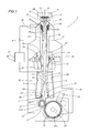
Figure 1 is a cross section, with some parts shown schematically and others cut away for clarity, of a feeding unit according to this invention; and -
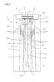
Figure 2 is an enlarged view of a detail of the unit ofFigure 1 . - With reference to
Figure 1 , thenumeral 1 denotes in its entirety a unit for feeding a risingflow 2 of cut tobacco. - In this description reference will be made to a feeding unit installed on
cigarette making machines 1 of the twin line type, which are therefore able to operate on twocords 3 of tobacco at the same time. - As shown in
Figure 1 , theunit 1 for feeding a risingflow 2 of cut tobacco comprises achannel 4 for feeding theflow 2, thechannel 4 being delimited by a first 5 and a secondmajor wall 6, facing each other and substantially vertical, and having alower cross-section 7 for the tobacco infeed and anupper cross-section 8 for the tobacco outfeed. At the upperoutfeed cross-section 8 there are twosuction belts 9 for transporting the tobacco, separated from each other by abaffle 10. - The
suction belts 9, preferably parallel to each other, are movable in a direction of motion perpendicular to the plane ofFigure 1 and transversal to the axis A of longitudinal extension of thechannel 4. Preferably, thebelts 9 are made from fabric material which is permeable to air. - The
baffle 10 interposed between the twobelts 9 faces towards the inside of thechannel 4 and it comprises a bar parallel to the longitudinal extension of thesuction belts 9. - The
unit 1 also comprises means 11 for generating theflow 2 designed for conveying the tobacco with a substantially uniform distribution through anintermediate cross-section 12 of thechannel 4, which is interposed between thelower cross-section 7 and theupper cross-section 8. Moreover, thewalls channel 4 converge on each other, from theintermediate cross-section 12 to theupper cross-section 8 and form, more specifically,deflector elements 13 of theflow 2 towards thebelts 9. Looking in more detail, according to the preferred embodiment, thechannel 4 is defined by afirst stretch 14, asecond stretch 15 and athird end stretch 16. - More specifically, the
channel 4 has, from the bottom upwards, afirst stretch 14 with converging walls, asecond stretch 15 with diverging walls and athird stretch 16 with walls converging in the direction of theoutfeed cross-section 8 of thechannel 4. - The term "stretch" means a a defined portion of the
channel 4, and specifically in this description the portions are connected to each other and consecutive in pairs. - Moreover, the
third end stretch 16 extends, from theintermediate cross-section 12 to theupper cross-section 8 of thechannel 4, for a length substantially equal to one third of the entire length of thechannel 4. More specifically, theend stretch 16 of thechannel 4 extends for a length, that is, is selected, between 250 mm and 300 mm. Further, the angle of inclination, relative to the longitudinal axis A of thechannel 4, of thewalls end stretch 16 of thechannel 4 is, that is, is selected, between 1° and 1 °30', preferably 1 °2'. - The
means 11 for generating theflow 2 comprise a mechanical needle-type device 17 for launching the cut tobacco located at the inlet to thechannel 4, mixing means 18 of theflow 2 of cut tobacco located at thelower cross-section 7 and regulatingmeans 19 designed to direct the risingflow 2 of tobacco. - The
mechanical launching device 17 comprises a pair of rotary rollers with axes at right angles to the axis A of thechannel 4 and operating in conjunction one with another. Thefirst roller 20, the so-called conveyor roller, picks up the tobacco fed from astorage hopper 23, whilst thesecond roller 21, the so-called launching roller, projects the tobacco upwards, inside thechannel 4. Eachroller relative periphery needles 22 extending radially from the periphery. - The mixing means 18 are formed by jets of compressed air introduced into the channel through each of the
major walls source 24 of compressed air connected with arespective homogenisation chamber 25 for eachwall channel 4. Thehomogenisation chambers 25 in turn communicate with the inside of thechannel 4 through respectiveinfeed ducts 26, which lead inside thechannel 4 throughperforations 27 of themajor walls flow 2 of tobacco in a direction facing thebelts 9. More specifically, the jets can be supplied and regulated independently from one another. - On the other hand, the
means 19 for regulating theflow 2 of cut tobacco comprise a pair ofwalls 28 movable inside thechannel 4, commonly known by the term "flaps". Preferably, thewalls 28 are movable independently from one another. Themeans 19 for regulating theflow 2 regulate opportunely the trajectory of the risingflow 2 so as to have an adequate correction, for example, if there is a greater concentration of tobacco on onebelt 9 rather than the other. - In the preferred embodiment, the
walls 28 are located at the seconddiverging stretch 11 of thechannel 4. - According to alternative embodiments, not illustrated, the
walls 28 can be located at other stretches of thechannel 4. - As shown in
Figure 1 , thewalls 28 are movable so as to produce a smaller divergence of thesecond stretch 15 when moved. A manual registration of the position of thewalls 28 is possible, either assisted or automatic. - The
feed unit 1 comprises achamber 29 for extracting the air present in thechannel 4 through the upperoutfeed cross-section 8 of thechannel 4. More in detail, thechamber 29 creates a negative pressure inside thechannel 4 which is able to draw the tobacco, from the bottom upwards, in the direction of theoutfeed cross-section 8. - Moreover, there are also means 30 for accelerating the
flow 2 of cut tobacco at theend stretch 16 of the channel 4 (Figure 2 ). The accelerator means 30 are positioned at each of themajor walls channel 4, close to theoutfeed cross-section 8. - The accelerator means 30 comprise a plurality of
ducts 31 connected to asuction unit 32, positioned outside thechannel 4, and leading inside thechannel 4 through a plurality ofholes 33, made in thewalls external suction unit 32 coincides with thesource 24 of compressed air of the mixing means 18, described above. - Also, more preferably, the
holes 33, made on themajor walls channel 4, have inclined axes. - The function of the accelerator means 30 is to increase the negative pressure inside the
channel 4 regulating and facilitating the rise of the cut tobacco and the feeding to thesuction belts 9. - According to an embodiment not illustrated, the
unit 1 also comprises pneumatic means for forming and introducing a flow of air rising along thechannel 4. - The flow of air, the source of which preferably coincides with the
source 24 of compressed air, is introduced at thelower cross-section 7 of thechannel 4. The tobacco is therefore facilitated in its rising in the direction of thesuction belts 9 under the pushing action of the flow of air. - As described above, the
walls channel 4, from theintermediate cross-section 12 to the upperoutfeed cross-section 8, act asdeflector elements 13 for the rising cut tobacco. - In more detail, in order to guarantee a balanced subdivision of the rising tobacco between each
suction belt 9, so as to guarantee feeding of an equal quantity of tobacco to eachbelt 9, thechannel 4 has therelative end stretch 16 with converging walls. - Moreover, in order to obtain an effective result, it is desirable that the
flow 2 of tobacco entering theend stretch 16, at theintermediate cross-section 12, is characterised by a homogeneous and uniform distribution of the tobacco. - The walls of the
end stretch 16 act asdeflector elements 13 since they direct the tobacco present in theoutermost area 34 of the risingflow 2 towards theinnermost area 35 of theflow 2. In this way, a greater concentration of cut tobacco is obtained at theoutermost area 34 of theflow 2, whilst the distribution density at theinnermost area 35 remains unaltered and equal to that obtained, using the above-mentioned generation means 11, at theintermediate cross-section 12. - With a greater concentration of tobacco in the outermost area 34 a greater quantity of tobacco can be conveyed, and equally shared, to each
belt 9. At the same time, advantageously, the quantity of tobacco which impacts on theseparator baffle 10 reduces. A homogenisation of the tobacco at theintermediate cross-section 12 allows the quantity of tobacco which impacts on thebaffle 10 to be minimised, thereby preventing possible deviations to the risingflow 2 close to thesuction belts 9 and favouring a more equal sharing of the tobacco. - In use, the cut tobacco, fed from the
storage hopper 23, is introduced inside thechannel 4 by the mechanical needle-type launching device 17. - The rising of the tobacco takes place not only by means of the inertia imparted by the
launching device 23 but also by means of a negative pressure present inside thechannel 4, made using theextraction chamber 29 and the accelerator means 30, which draws the tobacco, from the bottom upwards, in the direction of theoutfeed cross-section 8 of thechannel 4. - During the rising, in the direction of the
suction belts 9, the cut tobacco is redistributed, so as to obtain a homogeneous distribution of theflow 2 at theintermediate cross-section 12 of thechannel 4. More specifically, the mixing jets, positioned at the infeed of thechannel 4, create a re-mixing of theflow 2 which favours a homogeneous distribution of the tobacco at theintermediate cross-section 12. - This aspect is particularly advantageous since, as described above, during the transit through the
end stretch 16, the tobacco is thickened in theoutermost area 34 of the risingflow 2. - As described above, the tobacco firstly reaches the
intermediate cross-section 12 with a homogeneous distribution in theflow 2, and then touches the converging walls of theend stretch 16, undergoing a mechanical action of deviation towards theinnermost area 35 of theflow 2 and a consequent accumulation with the tobacco innermost to theflow 2. - In this way, a better sharing of the rising tobacco is obtained between the
suction conveyor belts 9 and at the same time there is a reduction in the quantity of tobacco which, impacting against theseparator baffle 10, would create deviations in thelifting flow 2, and, therefore, an incorrect distribution of the tobacco. - Further, in order to improve and guarantee an equal distribution of the tobacco, the trajectory of the rising
flow 2 is regulated. - The trajectory of the
flow 2 of tobacco is regulated using themovable walls 28 of the regulating means 19 so as to compensate for any incorrect distribution between the twosuction belts 9. - Lastly, the cut tobacco is transferred, held by the
suction belts 9, in the form of twocontinuous cords 3 of tobacco. - The invention described offers important advantages.
- Firstly, an optimum distribution of the tobacco is obtained between each
suction conveyor belt 9. More specifically, theunit 1 allows a better balancing of the quantity of tobacco distributed to eachbelt 9 limiting the quantity of tobacco which impacts on theseparator baffle 10. - The
feed unit 1 as describes has overall a simple constructional geometry and it is easy and fast to make and install. - This latter aspect therefore limits both the construction costs and the costs in the case of modifying existing units.
- The invention described above is susceptible of industrial application and may be modified and adapted in several ways without thereby departing from the scope of the inventive concept. Moreover, all the details of the invention may be substituted by technically equivalent elements.
Claims (10)
- A unit for feeding a rising flow of cut tobacco of a twin-rod cigarette making machine; the unit (1) comprising a channel (4) for feeding the flow (2), which is delimited by two major walls (5, 6), facing each other and substantially vertical, and has a lower cross-section (7) for the tobacco infeed and an upper cross-section (8) for the tobacco outfeed, at which two suction belts (9) for transporting the tobacco are positioned, separated from each other by a baffle (10); the unit being characterised in that it comprises means (11) for generating the flow (2) designed for conveying the tobacco with a substantially uniform distribution through an intermediate cross-section (12) of the channel (4), which is interposed between the lower cross-section (7) and the upper cross-section (8); and in that the walls (5, 6) of the channel (4) converge on each other, from the intermediate cross-section (12) to the upper cross-section (8) and form deflectors elements (13) of the flow (2) towards the belts (9).
- The feed unit according to claim 1, characterised in that the means (11) for generating the flow (2) comprise a mechanical needle-type device (17) for launching the cut tobacco located at the inlet to the channel (4), mixing means (18) of the flow (2) of cut tobacco located close to the lower cross-section (7) of the channel (4) and regulating means (19) designed to direct the rising flow (2) of tobacco.
- The feed unit according to claim 2, characterised in that the mechanical needle-type launching device (17) is formed by a pair of rotary rollers (20, 21) operating in conjunction one with another; each roller (20, 21) having on the relative periphery (20a, 21 a) a plurality of needles (22) extending radially from the periphery (20a, 21 a).
- The feed unit according to claim 2 or 3, characterised in that the mixing means (18) are formed by jets of compressed air introduced through each of the major walls (5, 6) of the channel (4).
- The feed unit according to claim 4, characterised in that the jets are supplied and regulated independently from one another.
- The feed unit according to any one of claims 2 to 5, characterised in that the regulating means (19) of the flow (2) of cut tobacco comprise a pair of walls (28) movable inside the channel (4).
- The feed unit according to claim 6, characterised in that the walls (28) are movable independently from one another.
- The feed unit according to any preceding claim, characterised in that the section of channel (4), from the intermediate cross-section (12) to the upper cross-section (8), extends for a length substantially equal to one third of the entire length of the channel (4).
- The feed unit according to any preceding claim, characterised in that the section of channel (4), from the intermediate cross-section (12) to the upper cross-section (8), extends for a length of between 250 mm and 300 mm.
- The feed unit according to any preceding claim, characterised in that the angle of inclination of the walls (5, 6) of the channel (4), from the intermediate cross-section (12) to the upper cross-section (8), is between 1 ° and 1 °30', preferably 1 °2', relative to a longitudinal axis of extension (A) of the channel (4).
Applications Claiming Priority (1)
| Application Number | Priority Date | Filing Date | Title |
|---|---|---|---|
| IT000734A ITBO20110734A1 (en) | 2011-12-20 | 2011-12-20 | POWER SUPPLY UNIT OF A SHREDDED CONCENTRATED TOBACCO FLOW OF A DOUBLE BOTTLE CIGARETTE PACKAGING MACHINE. |
Publications (2)
| Publication Number | Publication Date |
|---|---|
| EP2606753A1 true EP2606753A1 (en) | 2013-06-26 |
| EP2606753B1 EP2606753B1 (en) | 2016-08-17 |
Family
ID=45809397
Family Applications (1)
| Application Number | Title | Priority Date | Filing Date |
|---|---|---|---|
| EP12197156.8A Not-in-force EP2606753B1 (en) | 2011-12-20 | 2012-12-14 | A unit for feeding a rising flow of cut tobacco of a twin-rod cigarette making machine |
Country Status (2)
| Country | Link |
|---|---|
| EP (1) | EP2606753B1 (en) |
| IT (1) | ITBO20110734A1 (en) |
Cited By (4)
| Publication number | Priority date | Publication date | Assignee | Title |
|---|---|---|---|---|
| CN112438425A (en) * | 2020-12-07 | 2021-03-05 | 许昌富思特烟机配件有限公司 | Cigarette machine flue structure with adjustable negative pressure |
| US11154070B2 (en) | 2015-11-20 | 2021-10-26 | Upfield Europe B.V. | Process for preparing fat continuous emulsions low in fat |
| US11154069B2 (en) | 2015-11-20 | 2021-10-26 | Upfield Europe B.V. | Process for preparing fat continuous emulsions containing protein |
| US12075793B2 (en) | 2015-11-20 | 2024-09-03 | Upfield Europe B.V. | Process for preparing fat continuous emulsions |
Citations (7)
| Publication number | Priority date | Publication date | Assignee | Title |
|---|---|---|---|---|
| GB2077568A (en) * | 1980-05-26 | 1981-12-23 | Gd Spa | Simultaneous reproduction of two continuous cigarette rods |
| DE3835335A1 (en) * | 1987-10-20 | 1989-05-03 | Gd Spa | DEVICE FOR SUPPLYING TOBACCO FLOWS TO A CIGARETTE PRODUCTION MACHINE |
| GB2240026A (en) * | 1990-01-18 | 1991-07-24 | Koerber Ag | Making plural tobacco tiller streams |
| GB2255268A (en) * | 1991-04-30 | 1992-11-04 | Koerber Ag | Method of and apparatus for simultaneously producing two continuous tobacco streams |
| DE4136470A1 (en) * | 1991-11-06 | 1993-05-13 | Hauni Werke Koerber & Co Kg | Formation of two streams of tobacco from single stream - by alternate operation of two jets of air on opposite sides of single stream |
| GB2271921A (en) * | 1992-10-28 | 1994-05-04 | Gd Spa | Method of simultaneously producing two continuous cigarette rods |
| EP1859693A1 (en) * | 2006-05-22 | 2007-11-28 | G.D.S. S.p.A. | A cigarette making machine equipped to manufacture two continuous cigarette rods simultaneously |
-
2011
- 2011-12-20 IT IT000734A patent/ITBO20110734A1/en unknown
-
2012
- 2012-12-14 EP EP12197156.8A patent/EP2606753B1/en not_active Not-in-force
Patent Citations (7)
| Publication number | Priority date | Publication date | Assignee | Title |
|---|---|---|---|---|
| GB2077568A (en) * | 1980-05-26 | 1981-12-23 | Gd Spa | Simultaneous reproduction of two continuous cigarette rods |
| DE3835335A1 (en) * | 1987-10-20 | 1989-05-03 | Gd Spa | DEVICE FOR SUPPLYING TOBACCO FLOWS TO A CIGARETTE PRODUCTION MACHINE |
| GB2240026A (en) * | 1990-01-18 | 1991-07-24 | Koerber Ag | Making plural tobacco tiller streams |
| GB2255268A (en) * | 1991-04-30 | 1992-11-04 | Koerber Ag | Method of and apparatus for simultaneously producing two continuous tobacco streams |
| DE4136470A1 (en) * | 1991-11-06 | 1993-05-13 | Hauni Werke Koerber & Co Kg | Formation of two streams of tobacco from single stream - by alternate operation of two jets of air on opposite sides of single stream |
| GB2271921A (en) * | 1992-10-28 | 1994-05-04 | Gd Spa | Method of simultaneously producing two continuous cigarette rods |
| EP1859693A1 (en) * | 2006-05-22 | 2007-11-28 | G.D.S. S.p.A. | A cigarette making machine equipped to manufacture two continuous cigarette rods simultaneously |
Cited By (4)
| Publication number | Priority date | Publication date | Assignee | Title |
|---|---|---|---|---|
| US11154070B2 (en) | 2015-11-20 | 2021-10-26 | Upfield Europe B.V. | Process for preparing fat continuous emulsions low in fat |
| US11154069B2 (en) | 2015-11-20 | 2021-10-26 | Upfield Europe B.V. | Process for preparing fat continuous emulsions containing protein |
| US12075793B2 (en) | 2015-11-20 | 2024-09-03 | Upfield Europe B.V. | Process for preparing fat continuous emulsions |
| CN112438425A (en) * | 2020-12-07 | 2021-03-05 | 许昌富思特烟机配件有限公司 | Cigarette machine flue structure with adjustable negative pressure |
Also Published As
| Publication number | Publication date |
|---|---|
| EP2606753B1 (en) | 2016-08-17 |
| ITBO20110734A1 (en) | 2013-06-21 |
Similar Documents
| Publication | Publication Date | Title |
|---|---|---|
| CN1241501C (en) | Device for forming at least one tobacco bunch for cigarette making machine | |
| EP2606753B1 (en) | A unit for feeding a rising flow of cut tobacco of a twin-rod cigarette making machine | |
| US8827673B2 (en) | Device for dry-forming a fibrous web | |
| CN105361240A (en) | Tobacco shred guide device, tobacco shred feeding device, system and tobacco shred feeding method | |
| PL208912B1 (en) | Method of manufacture of at least two tobacco bands on a cigarette band producing machine, equipment for manufacture of at least two tobacco bands on a cigarette band producing machine, use of at least two pile up stations to produce tobacco bands, also a | |
| US20060096606A1 (en) | Device for processing tobacco during the production of cigarettes | |
| EP1859693B1 (en) | A cigarette making machine equipped to manufacture two continuous cigarette rods simultaneously | |
| US20190289898A1 (en) | Heavies removal device for tobacco airflow separator | |
| CN101394760B (en) | Deflecting device, machine comprising such a deflecting device, and method for conveying and deflecting at least one continuous filter tow | |
| CN104055220B (en) | Cigarette machine feed sett frame and operation method thereof | |
| CN101023809B (en) | Guiding member of cigarette rolling machine | |
| CN202154018U (en) | Tobacco stalk straightening equipment | |
| US7802578B2 (en) | Shredded tobacco supply device for a cigarette manufacturing machine | |
| CN110395580B (en) | Separate chamber type wire feeding machine and working method thereof | |
| CN100353877C (en) | Tobacco making machine | |
| JP2005306611A (en) | Conveyor table | |
| CN102333460B (en) | A unit for feeding a flow of tobacco particles in a cigarette maker | |
| EP0745335B1 (en) | Method and unit for supplying a cigarette manufacturing machine | |
| CN205052857U (en) | Cut quick -witted feeding of stalk silk screening guiding device | |
| US20050087199A1 (en) | Device for separating tobacco and transport air and arrangement and method for forming at least two tobacco rods in an endless rod maker | |
| EP3678941B1 (en) | Hopper for smoking articles | |
| CN101986904B (en) | Manufacture method of tobacco strips and air groove | |
| CN202644296U (en) | Arrangement in the tail threading of a full width web in the dryer section of a fiber web machine | |
| CN203699292U (en) | Material evening device with material storage function and cut tobacco processing system | |
| CN101166430B (en) | Cordon forming device comprising an air flow barrier |
Legal Events
| Date | Code | Title | Description |
|---|---|---|---|
| AK | Designated contracting states |
Kind code of ref document: A1 Designated state(s): AL AT BE BG CH CY CZ DE DK EE ES FI FR GB GR HR HU IE IS IT LI LT LU LV MC MK MT NL NO PL PT RO RS SE SI SK SM TR |
|
| AX | Request for extension of the european patent |
Extension state: BA ME |
|
| PUAI | Public reference made under article 153(3) epc to a published international application that has entered the european phase |
Free format text: ORIGINAL CODE: 0009012 |
|
| 17P | Request for examination filed |
Effective date: 20131119 |
|
| RBV | Designated contracting states (corrected) |
Designated state(s): AL AT BE BG CH CY CZ DE DK EE ES FI FR GB GR HR HU IE IS IT LI LT LU LV MC MK MT NL NO PL PT RO RS SE SI SK SM TR |
|
| GRAP | Despatch of communication of intention to grant a patent |
Free format text: ORIGINAL CODE: EPIDOSNIGR1 |
|
| RIC1 | Information provided on ipc code assigned before grant |
Ipc: A24C 5/18 20060101AFI20160215BHEP |
|
| INTG | Intention to grant announced |
Effective date: 20160316 |
|
| GRAS | Grant fee paid |
Free format text: ORIGINAL CODE: EPIDOSNIGR3 |
|
| GRAA | (expected) grant |
Free format text: ORIGINAL CODE: 0009210 |
|
| AK | Designated contracting states |
Kind code of ref document: B1 Designated state(s): AL AT BE BG CH CY CZ DE DK EE ES FI FR GB GR HR HU IE IS IT LI LT LU LV MC MK MT NL NO PL PT RO RS SE SI SK SM TR |
|
| REG | Reference to a national code |
Ref country code: GB Ref legal event code: FG4D |
|
| REG | Reference to a national code |
Ref country code: CH Ref legal event code: EP |
|
| REG | Reference to a national code |
Ref country code: IE Ref legal event code: FG4D |
|
| REG | Reference to a national code |
Ref country code: AT Ref legal event code: REF Ref document number: 820165 Country of ref document: AT Kind code of ref document: T Effective date: 20160915 |
|
| REG | Reference to a national code |
Ref country code: DE Ref legal event code: R096 Ref document number: 602012021787 Country of ref document: DE |
|
| REG | Reference to a national code |
Ref country code: NL Ref legal event code: MP Effective date: 20160817 |
|
| REG | Reference to a national code |
Ref country code: FR Ref legal event code: PLFP Year of fee payment: 5 Ref country code: LT Ref legal event code: MG4D |
|
| REG | Reference to a national code |
Ref country code: AT Ref legal event code: MK05 Ref document number: 820165 Country of ref document: AT Kind code of ref document: T Effective date: 20160817 |
|
| PG25 | Lapsed in a contracting state [announced via postgrant information from national office to epo] |
Ref country code: NL Free format text: LAPSE BECAUSE OF FAILURE TO SUBMIT A TRANSLATION OF THE DESCRIPTION OR TO PAY THE FEE WITHIN THE PRESCRIBED TIME-LIMIT Effective date: 20160817 Ref country code: NO Free format text: LAPSE BECAUSE OF FAILURE TO SUBMIT A TRANSLATION OF THE DESCRIPTION OR TO PAY THE FEE WITHIN THE PRESCRIBED TIME-LIMIT Effective date: 20161117 Ref country code: FI Free format text: LAPSE BECAUSE OF FAILURE TO SUBMIT A TRANSLATION OF THE DESCRIPTION OR TO PAY THE FEE WITHIN THE PRESCRIBED TIME-LIMIT Effective date: 20160817 Ref country code: HR Free format text: LAPSE BECAUSE OF FAILURE TO SUBMIT A TRANSLATION OF THE DESCRIPTION OR TO PAY THE FEE WITHIN THE PRESCRIBED TIME-LIMIT Effective date: 20160817 Ref country code: LT Free format text: LAPSE BECAUSE OF FAILURE TO SUBMIT A TRANSLATION OF THE DESCRIPTION OR TO PAY THE FEE WITHIN THE PRESCRIBED TIME-LIMIT Effective date: 20160817 Ref country code: IT Free format text: LAPSE BECAUSE OF FAILURE TO SUBMIT A TRANSLATION OF THE DESCRIPTION OR TO PAY THE FEE WITHIN THE PRESCRIBED TIME-LIMIT Effective date: 20160817 Ref country code: RS Free format text: LAPSE BECAUSE OF FAILURE TO SUBMIT A TRANSLATION OF THE DESCRIPTION OR TO PAY THE FEE WITHIN THE PRESCRIBED TIME-LIMIT Effective date: 20160817 |
|
| PGFP | Annual fee paid to national office [announced via postgrant information from national office to epo] |
Ref country code: GB Payment date: 20161228 Year of fee payment: 5 |
|
| PG25 | Lapsed in a contracting state [announced via postgrant information from national office to epo] |
Ref country code: PT Free format text: LAPSE BECAUSE OF FAILURE TO SUBMIT A TRANSLATION OF THE DESCRIPTION OR TO PAY THE FEE WITHIN THE PRESCRIBED TIME-LIMIT Effective date: 20161219 Ref country code: SE Free format text: LAPSE BECAUSE OF FAILURE TO SUBMIT A TRANSLATION OF THE DESCRIPTION OR TO PAY THE FEE WITHIN THE PRESCRIBED TIME-LIMIT Effective date: 20160817 Ref country code: ES Free format text: LAPSE BECAUSE OF FAILURE TO SUBMIT A TRANSLATION OF THE DESCRIPTION OR TO PAY THE FEE WITHIN THE PRESCRIBED TIME-LIMIT Effective date: 20160817 Ref country code: AT Free format text: LAPSE BECAUSE OF FAILURE TO SUBMIT A TRANSLATION OF THE DESCRIPTION OR TO PAY THE FEE WITHIN THE PRESCRIBED TIME-LIMIT Effective date: 20160817 Ref country code: LV Free format text: LAPSE BECAUSE OF FAILURE TO SUBMIT A TRANSLATION OF THE DESCRIPTION OR TO PAY THE FEE WITHIN THE PRESCRIBED TIME-LIMIT Effective date: 20160817 Ref country code: PL Free format text: LAPSE BECAUSE OF FAILURE TO SUBMIT A TRANSLATION OF THE DESCRIPTION OR TO PAY THE FEE WITHIN THE PRESCRIBED TIME-LIMIT Effective date: 20160817 Ref country code: GR Free format text: LAPSE BECAUSE OF FAILURE TO SUBMIT A TRANSLATION OF THE DESCRIPTION OR TO PAY THE FEE WITHIN THE PRESCRIBED TIME-LIMIT Effective date: 20161118 |
|
| PG25 | Lapsed in a contracting state [announced via postgrant information from national office to epo] |
Ref country code: RO Free format text: LAPSE BECAUSE OF FAILURE TO SUBMIT A TRANSLATION OF THE DESCRIPTION OR TO PAY THE FEE WITHIN THE PRESCRIBED TIME-LIMIT Effective date: 20160817 Ref country code: EE Free format text: LAPSE BECAUSE OF FAILURE TO SUBMIT A TRANSLATION OF THE DESCRIPTION OR TO PAY THE FEE WITHIN THE PRESCRIBED TIME-LIMIT Effective date: 20160817 |
|
| REG | Reference to a national code |
Ref country code: DE Ref legal event code: R097 Ref document number: 602012021787 Country of ref document: DE |
|
| PG25 | Lapsed in a contracting state [announced via postgrant information from national office to epo] |
Ref country code: SM Free format text: LAPSE BECAUSE OF FAILURE TO SUBMIT A TRANSLATION OF THE DESCRIPTION OR TO PAY THE FEE WITHIN THE PRESCRIBED TIME-LIMIT Effective date: 20160817 Ref country code: BG Free format text: LAPSE BECAUSE OF FAILURE TO SUBMIT A TRANSLATION OF THE DESCRIPTION OR TO PAY THE FEE WITHIN THE PRESCRIBED TIME-LIMIT Effective date: 20161117 Ref country code: BE Free format text: LAPSE BECAUSE OF FAILURE TO SUBMIT A TRANSLATION OF THE DESCRIPTION OR TO PAY THE FEE WITHIN THE PRESCRIBED TIME-LIMIT Effective date: 20160817 Ref country code: DK Free format text: LAPSE BECAUSE OF FAILURE TO SUBMIT A TRANSLATION OF THE DESCRIPTION OR TO PAY THE FEE WITHIN THE PRESCRIBED TIME-LIMIT Effective date: 20160817 Ref country code: CZ Free format text: LAPSE BECAUSE OF FAILURE TO SUBMIT A TRANSLATION OF THE DESCRIPTION OR TO PAY THE FEE WITHIN THE PRESCRIBED TIME-LIMIT Effective date: 20160817 Ref country code: SK Free format text: LAPSE BECAUSE OF FAILURE TO SUBMIT A TRANSLATION OF THE DESCRIPTION OR TO PAY THE FEE WITHIN THE PRESCRIBED TIME-LIMIT Effective date: 20160817 |
|
| PLBE | No opposition filed within time limit |
Free format text: ORIGINAL CODE: 0009261 |
|
| STAA | Information on the status of an ep patent application or granted ep patent |
Free format text: STATUS: NO OPPOSITION FILED WITHIN TIME LIMIT |
|
| 26N | No opposition filed |
Effective date: 20170518 |
|
| REG | Reference to a national code |
Ref country code: CH Ref legal event code: PL |
|
| PG25 | Lapsed in a contracting state [announced via postgrant information from national office to epo] |
Ref country code: SI Free format text: LAPSE BECAUSE OF FAILURE TO SUBMIT A TRANSLATION OF THE DESCRIPTION OR TO PAY THE FEE WITHIN THE PRESCRIBED TIME-LIMIT Effective date: 20160817 |
|
| PG25 | Lapsed in a contracting state [announced via postgrant information from national office to epo] |
Ref country code: MC Free format text: LAPSE BECAUSE OF FAILURE TO SUBMIT A TRANSLATION OF THE DESCRIPTION OR TO PAY THE FEE WITHIN THE PRESCRIBED TIME-LIMIT Effective date: 20160817 |
|
| REG | Reference to a national code |
Ref country code: IE Ref legal event code: MM4A |
|
| PG25 | Lapsed in a contracting state [announced via postgrant information from national office to epo] |
Ref country code: LI Free format text: LAPSE BECAUSE OF NON-PAYMENT OF DUE FEES Effective date: 20161231 Ref country code: LU Free format text: LAPSE BECAUSE OF NON-PAYMENT OF DUE FEES Effective date: 20161214 Ref country code: CH Free format text: LAPSE BECAUSE OF NON-PAYMENT OF DUE FEES Effective date: 20161231 |
|
| PG25 | Lapsed in a contracting state [announced via postgrant information from national office to epo] |
Ref country code: IE Free format text: LAPSE BECAUSE OF NON-PAYMENT OF DUE FEES Effective date: 20161214 |
|
| REG | Reference to a national code |
Ref country code: FR Ref legal event code: PLFP Year of fee payment: 6 |
|
| PG25 | Lapsed in a contracting state [announced via postgrant information from national office to epo] |
Ref country code: HU Free format text: LAPSE BECAUSE OF FAILURE TO SUBMIT A TRANSLATION OF THE DESCRIPTION OR TO PAY THE FEE WITHIN THE PRESCRIBED TIME-LIMIT; INVALID AB INITIO Effective date: 20121214 Ref country code: CY Free format text: LAPSE BECAUSE OF FAILURE TO SUBMIT A TRANSLATION OF THE DESCRIPTION OR TO PAY THE FEE WITHIN THE PRESCRIBED TIME-LIMIT Effective date: 20160817 |
|
| PG25 | Lapsed in a contracting state [announced via postgrant information from national office to epo] |
Ref country code: TR Free format text: LAPSE BECAUSE OF FAILURE TO SUBMIT A TRANSLATION OF THE DESCRIPTION OR TO PAY THE FEE WITHIN THE PRESCRIBED TIME-LIMIT Effective date: 20160817 Ref country code: IS Free format text: LAPSE BECAUSE OF FAILURE TO SUBMIT A TRANSLATION OF THE DESCRIPTION OR TO PAY THE FEE WITHIN THE PRESCRIBED TIME-LIMIT Effective date: 20160817 Ref country code: MK Free format text: LAPSE BECAUSE OF FAILURE TO SUBMIT A TRANSLATION OF THE DESCRIPTION OR TO PAY THE FEE WITHIN THE PRESCRIBED TIME-LIMIT Effective date: 20160817 |
|
| GBPC | Gb: european patent ceased through non-payment of renewal fee |
Effective date: 20171214 |
|
| PG25 | Lapsed in a contracting state [announced via postgrant information from national office to epo] |
Ref country code: MT Free format text: LAPSE BECAUSE OF NON-PAYMENT OF DUE FEES Effective date: 20161214 |
|
| PG25 | Lapsed in a contracting state [announced via postgrant information from national office to epo] |
Ref country code: AL Free format text: LAPSE BECAUSE OF FAILURE TO SUBMIT A TRANSLATION OF THE DESCRIPTION OR TO PAY THE FEE WITHIN THE PRESCRIBED TIME-LIMIT Effective date: 20160817 |
|
| PG25 | Lapsed in a contracting state [announced via postgrant information from national office to epo] |
Ref country code: GB Free format text: LAPSE BECAUSE OF NON-PAYMENT OF DUE FEES Effective date: 20171214 |
|
| PGFP | Annual fee paid to national office [announced via postgrant information from national office to epo] |
Ref country code: FR Payment date: 20191226 Year of fee payment: 8 |
|
| PGFP | Annual fee paid to national office [announced via postgrant information from national office to epo] |
Ref country code: DE Payment date: 20191231 Year of fee payment: 8 |
|
| REG | Reference to a national code |
Ref country code: DE Ref legal event code: R119 Ref document number: 602012021787 Country of ref document: DE |
|
| PG25 | Lapsed in a contracting state [announced via postgrant information from national office to epo] |
Ref country code: FR Free format text: LAPSE BECAUSE OF NON-PAYMENT OF DUE FEES Effective date: 20201231 |
|
| PG25 | Lapsed in a contracting state [announced via postgrant information from national office to epo] |
Ref country code: DE Free format text: LAPSE BECAUSE OF NON-PAYMENT OF DUE FEES Effective date: 20210701 |