EP2605977B1 - Container with perforated shrink wrap sleeve - Google Patents
Container with perforated shrink wrap sleeve Download PDFInfo
- Publication number
- EP2605977B1 EP2605977B1 EP11746135.0A EP11746135A EP2605977B1 EP 2605977 B1 EP2605977 B1 EP 2605977B1 EP 11746135 A EP11746135 A EP 11746135A EP 2605977 B1 EP2605977 B1 EP 2605977B1
- Authority
- EP
- European Patent Office
- Prior art keywords
- container
- shrink wrap
- sleeve
- wrap sleeve
- circumference
- Prior art date
- Legal status (The legal status is an assumption and is not a legal conclusion. Google has not performed a legal analysis and makes no representation as to the accuracy of the status listed.)
- Active
Links
- 238000013459 approach Methods 0.000 claims description 5
- -1 polyethylene terephthalate Polymers 0.000 description 10
- 229920000139 polyethylene terephthalate Polymers 0.000 description 8
- 239000005020 polyethylene terephthalate Substances 0.000 description 8
- 229920005644 polyethylene terephthalate glycol copolymer Polymers 0.000 description 8
- 235000014666 liquid concentrate Nutrition 0.000 description 7
- 239000007788 liquid Substances 0.000 description 5
- LYCAIKOWRPUZTN-UHFFFAOYSA-N Ethylene glycol Chemical compound OCCO LYCAIKOWRPUZTN-UHFFFAOYSA-N 0.000 description 4
- 239000004698 Polyethylene Substances 0.000 description 4
- 239000004743 Polypropylene Substances 0.000 description 4
- 229920000573 polyethylene Polymers 0.000 description 4
- 229920001155 polypropylene Polymers 0.000 description 4
- 238000002372 labelling Methods 0.000 description 3
- 239000000463 material Substances 0.000 description 3
- 238000004806 packaging method and process Methods 0.000 description 3
- 239000000853 adhesive Substances 0.000 description 2
- 230000001070 adhesive effect Effects 0.000 description 2
- WGCNASOHLSPBMP-UHFFFAOYSA-N hydroxyacetaldehyde Natural products OCC=O WGCNASOHLSPBMP-UHFFFAOYSA-N 0.000 description 2
- 239000000976 ink Substances 0.000 description 2
- 229920000098 polyolefin Polymers 0.000 description 2
- 239000004800 polyvinyl chloride Substances 0.000 description 2
- 229910052709 silver Inorganic materials 0.000 description 2
- 239000004332 silver Substances 0.000 description 2
- 229920006257 Heat-shrinkable film Polymers 0.000 description 1
- 235000008504 concentrate Nutrition 0.000 description 1
- 230000000694 effects Effects 0.000 description 1
- 239000002654 heat shrinkable material Substances 0.000 description 1
- 238000000034 method Methods 0.000 description 1
- 239000000203 mixture Substances 0.000 description 1
- 238000012986 modification Methods 0.000 description 1
- 230000004048 modification Effects 0.000 description 1
- 229920000642 polymer Polymers 0.000 description 1
- 238000007789 sealing Methods 0.000 description 1
- 229920006300 shrink film Polymers 0.000 description 1
- 238000011179 visual inspection Methods 0.000 description 1
Images


Classifications
-
- B—PERFORMING OPERATIONS; TRANSPORTING
- B65—CONVEYING; PACKING; STORING; HANDLING THIN OR FILAMENTARY MATERIAL
- B65D—CONTAINERS FOR STORAGE OR TRANSPORT OF ARTICLES OR MATERIALS, e.g. BAGS, BARRELS, BOTTLES, BOXES, CANS, CARTONS, CRATES, DRUMS, JARS, TANKS, HOPPERS, FORWARDING CONTAINERS; ACCESSORIES, CLOSURES, OR FITTINGS THEREFOR; PACKAGING ELEMENTS; PACKAGES
- B65D23/00—Details of bottles or jars not otherwise provided for
- B65D23/08—Coverings or external coatings
- B65D23/0842—Sheets or tubes applied around the bottle with or without subsequent folding operations
-
- B—PERFORMING OPERATIONS; TRANSPORTING
- B65—CONVEYING; PACKING; STORING; HANDLING THIN OR FILAMENTARY MATERIAL
- B65D—CONTAINERS FOR STORAGE OR TRANSPORT OF ARTICLES OR MATERIALS, e.g. BAGS, BARRELS, BOTTLES, BOXES, CANS, CARTONS, CRATES, DRUMS, JARS, TANKS, HOPPERS, FORWARDING CONTAINERS; ACCESSORIES, CLOSURES, OR FITTINGS THEREFOR; PACKAGING ELEMENTS; PACKAGES
- B65D55/00—Accessories for container closures not otherwise provided for
- B65D55/02—Locking devices; Means for discouraging or indicating unauthorised opening or removal of closure
- B65D55/06—Deformable or tearable wires, strings, or strips; Use of seals, e.g. destructible locking pins
- B65D55/08—Annular elements encircling container necks
- B65D55/0818—Destructible or permanently removable bands, e.g. adhesive
- B65D55/0854—Shrink-film bands
-
- B—PERFORMING OPERATIONS; TRANSPORTING
- B65—CONVEYING; PACKING; STORING; HANDLING THIN OR FILAMENTARY MATERIAL
- B65D—CONTAINERS FOR STORAGE OR TRANSPORT OF ARTICLES OR MATERIALS, e.g. BAGS, BARRELS, BOTTLES, BOXES, CANS, CARTONS, CRATES, DRUMS, JARS, TANKS, HOPPERS, FORWARDING CONTAINERS; ACCESSORIES, CLOSURES, OR FITTINGS THEREFOR; PACKAGING ELEMENTS; PACKAGES
- B65D55/00—Accessories for container closures not otherwise provided for
- B65D55/02—Locking devices; Means for discouraging or indicating unauthorised opening or removal of closure
- B65D55/026—Locking devices; Means for discouraging or indicating unauthorised opening or removal of closure initial opening or unauthorised access being indicated by a visual change using indicators other than tearable means, e.g. change of colour, pattern or opacity
-
- B—PERFORMING OPERATIONS; TRANSPORTING
- B65—CONVEYING; PACKING; STORING; HANDLING THIN OR FILAMENTARY MATERIAL
- B65D—CONTAINERS FOR STORAGE OR TRANSPORT OF ARTICLES OR MATERIALS, e.g. BAGS, BARRELS, BOTTLES, BOXES, CANS, CARTONS, CRATES, DRUMS, JARS, TANKS, HOPPERS, FORWARDING CONTAINERS; ACCESSORIES, CLOSURES, OR FITTINGS THEREFOR; PACKAGING ELEMENTS; PACKAGES
- B65D75/00—Packages comprising articles or materials partially or wholly enclosed in strips, sheets, blanks, tubes, or webs of flexible sheet material, e.g. in folded wrappers
- B65D75/002—Packages comprising articles or materials partially or wholly enclosed in strips, sheets, blanks, tubes, or webs of flexible sheet material, e.g. in folded wrappers in shrink films
-
- G—PHYSICS
- G09—EDUCATION; CRYPTOGRAPHY; DISPLAY; ADVERTISING; SEALS
- G09F—DISPLAYING; ADVERTISING; SIGNS; LABELS OR NAME-PLATES; SEALS
- G09F3/00—Labels, tag tickets, or similar identification or indication means; Seals; Postage or like stamps
- G09F3/02—Forms or constructions
- G09F3/0291—Labels or tickets undergoing a change under particular conditions, e.g. heat, radiation, passage of time
- G09F3/0292—Labels or tickets undergoing a change under particular conditions, e.g. heat, radiation, passage of time tamper indicating labels
-
- B—PERFORMING OPERATIONS; TRANSPORTING
- B65—CONVEYING; PACKING; STORING; HANDLING THIN OR FILAMENTARY MATERIAL
- B65D—CONTAINERS FOR STORAGE OR TRANSPORT OF ARTICLES OR MATERIALS, e.g. BAGS, BARRELS, BOTTLES, BOXES, CANS, CARTONS, CRATES, DRUMS, JARS, TANKS, HOPPERS, FORWARDING CONTAINERS; ACCESSORIES, CLOSURES, OR FITTINGS THEREFOR; PACKAGING ELEMENTS; PACKAGES
- B65D23/00—Details of bottles or jars not otherwise provided for
- B65D23/08—Coverings or external coatings
- B65D23/0842—Sheets or tubes applied around the bottle with or without subsequent folding operations
- B65D23/0878—Shrunk on the bottle
Definitions
- Generally vertical perforations descending from the shrink wrap top edge can converge progressively closer together as they approach the circumferential ring.
- the vertical perforations descending from the shrink wrap top edge can terminate at the circumferential ring or alternately about two perforations above the circumferential ring. Such a distance corresponds to the length between two perforations or more of the generally vertical perforations.
- the shrink wrap vertical perforations descending, from the shrink wrap top edge can begin with an initial perforation cut, followed by proportionally smaller perforation cuts, configured so that when the shrink wrap is applied to the container body, the larger cut forms as 'V' shape at a top of each vertical perforation to define a tab between the vertical perforations.
- the container body can generally have a planar front and rear surface, and a seal of the shrink wrap is vertically oriented along an edge of the rear surface.
- the container can have a container body having a vertical axis, a bottom surface, and a container opening ,having a top surface; a vertically oriented shrink wrap sleeve covering a portion of the container body and the container opening, a top edge of the shrink wrap sleeve allowing the top surface to remain exposed, and bottom edge of the shrink wrap sleeve allowing the bottom surface to remain exposed; the shrink wrap sleeve having a pair of generally vertical perforations descending from the shrink wrap sleeve top edge towards a circumferential perforation ring oriented below the container opening.
- the container can have a container body having a circumference variation along a vertical axis, a bottom surface, and a container opening having a top surface; a vertically oriented shrink wrap sleeve covering a portion of the circumference variation of the container body and the container opening, a top edge of the shrink wrap sleeve allowing the top surface to remain exposed, and bottom edge of the shrink wrap sleeve allowing the bottom surface remain exposed; the shrink wrap sleeve having a pair of generally vertical perforations descending from a distance below the shrink wrap sleeve top edge towards a circumferential perforation ring oriented below the container opening.
- a shrink wrap sleeve suitable for use for covering a portion of a container along a vertical axis having a circumference variation can have a top edge and bottom edge; the shrink wrap sleeve having a pair of generally vertical perforations descending from the shrink wrap sleeve top edge towards a circumferential perforation ring.
- Optional features of the present embodiments can include printed indicia and adhesive to bond the container to the shrink wrap sleeve.
- the shrink wrap sleeve of claim 14 can be a polyolefin, a polymer such as polyethylene terephthalate (PET), a copolymerized polyethylene terephthalate (PETG), polyethylene terephthalate glycol (PETG LV), polyvinyl chloride (PVC), polypropylene (PP), polyethylene (PE), and combinations thereof.
- PET polyethylene terephthalate
- PET LV copolymerized polyethylene terephthalate
- PETG LV polyethylene terephthalate glycol
- PVC polyvinyl chloride
- PP polypropylene
- PE polyethylene
- the shrink wrap sleeve is a PETG, and even a PETG LV.
- the shrink wrap film can have a gauge of between about 40 to 55 microns, and preferably about 45 microns.
- the shrink wrap sleeve can have a shrinkage rate of about 75 percent to about 85 percent, and a shrinkage ratio of about 2:1.
- containers with perforated shrink wrapped sleeves configured to provide easy partial removal, evidence of tamper, and product labeling - even with irregularly shaped and non-symmetrical containers.
- the present embodiments illustrate a cost efficient and easy open feature for consumers to obtain full product access.
- printed surfaces provides graphics and other types of printed information on a shrink wrapable film that can be transparent, translucent, opaque, or variations/combinations thereof.
- Metallic inks can also be provided to provide a silver or metallic hue.
- a maximum to minimum shrinkage ratio should be at least 2:1. It is noted that various product container sizes are possible so long as the shrink wrap can be maintained thereon even after a partial band of film has been removed.
- the shrink wrap film is applied as a sleeve. When a container bottom is present, it is preferably not encapsulated by the shrink wrap.
- a first pattern can be a pair of perforations axially oriented to the sleeve to form a tab; and a second pattern can be a generally circumferential ring pattern perpendicular to the axially oriented perforations to define an upper band for removal.
- the axial pair of perforations can terminate at or near (e.g., 1-5 mm or 1-3 perforations) above the circumferential ring.
- the patterns can be configured to remove the upper band of material in one motion or by removing first a vertical tab, and then the remaining portion of the upper band.
- the material for the shrink wrap should be configured to withstand multiple container flexing (e.g., at least 50 times). This feature is useful for a container that contains products, such as a beverage concentrate, that require the container to be squeezed to deliver product.
- the container 10 described herein can dispense a liquid concentrate in such a way as to enter the target liquid without substantial splashing or splatter while also causing sufficient turbulence or mixing within the target container between the liquid concentrate and the target liquid to form a generally homogenous end mixture without the use of extraneous utensils or shaking.
- the container can include a closed, first end 12 and a top, second end 14 having a hinged flip top cap 16 secured to a back surface 23 by a hinge 44.
- the first end 12 and the flip top cap 16 can be connected by a generally tubular sidewall 18, which can take any suitable cross section, including any polygonal shape, any curvilinear shape, or any combination thereof, to form a container interior.
- the container 10 can be sized for any number of uses and can specifically be in the range of 20 to 200 cc.
- the shrink wrap sleeve 30 is PETG.
- the gauge of the shrink wrap sleeve 30 can be about 40 to 55 microns, preferably about 45 microns.
- Shrinkage of the shrink wrap sleeve 30 can be at a shrinkage rate of about 75 percent to about85 percent (preferably about 76 percent) and have a shrink ratio selected to preferably withstand a shrinkage ratio of about 2:1.
- the shrink wrap sleeve 30 can provide printed surfaces for graphics and other types of printed information or indicia on film that can be transparent, translucent, opaque, or various combinations thereof.
- Metallic inks can also be provided to provide a silver or metallic hue.
- the container 10 preferably has a body having a circumference variation along an axis oriented to receive the shrink wrap sleeve 30, such as a vertical axis.
- circumference by the present term can mean a perimeter variation and can include circles, ellipses and other various curvilinear or geometric shaped cross-sections.
- container 10 is configured to receive a shrink wrap sleeve 30 along a vertical axis.
- the portion of the container body covered by shrink wrap sleeve 30 can have a circumference variation having a greater ( FIG. 1 ,18) or lesser ( FIG.
- the portion of the container body covered by the shrink wrap sleeve 30 can have a circumference variation having a greater ( FIG. 1 , 18) or lesser ( FIG. 13 , 80) circumference at at least one point between the shrink wrap top edge 22 and the shrink wrap bottom edge 20 as compared to adjacent portions of the circumference.
- This variation can preferably range from about 5 percent to about 200 percent, and most preferably at about 100 percent.
- distortion rates can be based on the following distortion percentage TABLE as follows: TABLE: Percent distortion Vertical bottle height position (mm) 135 62-80 117 50-62 110 15-50 120 0-15
- the perforation patterns can be varied but preferentially include a generally circumferential ring of perforations generally perpendicular to the vertical perforations 32.
- the vertical perforations 32 converge as they approach and terminate at the horizontal line 34.
- Large cuts 66 are added to the top end of the vertical perforations 32 to provide a splitting effect, a "V" 72, when applied to the container 10.
- the pair of "V"s 72 provides a peel tab 74 to allow easy removal by a user. It is noted that as a user pulls on the peel tab 74, a vertical tab 36 is generated as the shrink wrap ruptures between the perforations. It is also noted that any ruptured patterns allow a visual inspection of the container to reveal whether the container has ever been opened or tampered with after shrink wrapping has been placed on the container.
- FIG. 7 shows a variation of the position of the large cut 66 bellow the top edge 22 of the shrink wrap sleeve 30.
- the large cut 66 is placed below one or more normal perforation cuts on the top edge of the sleeve 30.
- the heat shrinking separates the shrink wrap to form a circular opening to assist in developing a vertical tab 36 without forming a distinct peel tab 74.
- FIG.. 8 shows a variation of the perforation pattern by terminating the vertical perforations 32 before they reach the horizontal ring 34. This can be defined by not placing one, two, or three perforations before it reaches horizontal ring 34.
- this non-perforated area 68 can have, a dimension 70 of about 1 to 5 mm, and preferably about 1 to 2 mm.
- FIG. 9 illustrates where only one of vertical perforations 32 has a non-perforated area 68.
- FIG. 10 illustrates a horizontal cut 78 so that as the vertical tab 36 is removed (See, e.g., FIG. 2 ) it separates from the shrink wrap sleeve 30 when it reaches the horizontal perforation ring.
- a user can pinch the tab 74. and pull the shrink wrap toward the horizontal ring 34 to form the vertical tab 36 ( FIG. 1 ).
- a user can continuously pull the vertical tab 36 until it approaches the horizontal ring 34, followed by a horizontal pull ( FIG. 2 ) to continue the shrink wrap rupture of the horizontal ring perforations until an upper shrink wrap band 38 is removed ( FIG. 3 ). Once the band 38 is removed, the lower shrink wrap band 40 remains and the product is ready for use.
- the shrink wrap 30 can be formed by a blank 28 from continuos film of PETG as shown in FIG. 12 .
- cut lines 50 define the size of the sleeve blank.28 as well as fold lines 48, seal area 42, copy limit 56, no live copy 58, no legal information 60 (since that portion on the shrink wrap wilt be removed prior to use), front panel print 62, and rear panel print 64.
- the film is sealed at the seal area 42 and the perforations 32 and 34 are added to form the shrink wrap seal that is ready for placement on the container 10. It is noted that there are limitless variations that are possible to forming blanks for heat shrinking onto a containers.
Description
- The present products and methods rebate to packaging, and in particular to easy open containers having a perforated shrink wrap sleeve.
- Sealing product containers, labeling container contents and providing evidence that a container has not been opened are known using heat-shrinkable films ('shrink wrap'). Applying such films are described in
U.S. Patent No. 6,296,129 to Kawasaki andU.S. Patent No. 5,605,230 to Marino et al. . Shrink wrap applications can be economically applied to a variety of containers for a variety of products, such as food or pharmaceutical applications. - Despite the advantages of heat shrink films, shrink wrap packaging can sometimes be difficult for irregularly shaped containers. In such cases, shrink wrap can be difficult to apply, difficult to remove, and difficult to provide printed matter without noticeable distortion.
-
WO-A-00/48161 -
US-B-3733002 describes sealed containers which have closing means. A heat shrinkable sleeve surrounds the container, which has a circumferential tearing line. -
US-A-2005/0258131 describes a container which has a tamper-evident band arranged around the closure. The band has at least one tear strip defined by two parallel perforated lines - The problems of the packagings of the prior art are solved by a container according to claim 1. Accordingly, provided herein are perforated shrink wrap sleeves and containers with perforated shrink wrapped sleeves configured to provide easy partial removal, evidence of tamper, and product labeling - even with irregularly shaped and non-symmetrical containers.
- Preferably a container is provided having a container body that can have a circumference/perimeter variation along a vertical axis, a bottom surface, and a container opening having a top surface; an axially oriented shrink wrap sleeve covering a portion of the body of the container having a circumference variation and the container opening, a top edge of the shrink wrap sleeve allowing the top surface to remain exposed, and bottom edge of the shrink wrap sleeve allowing the bottom surface to remain exposed; the shrink wrap sleeve having a pair of generally vertical perforations descending from the shrink wrap top edge towards a circumferential perforation ring oriented below the container opening. Alternatively, the axially oriented shrink wrap sleeve covering a portion of the container body circumference variation has a greater circumference as compared to adjacent portions of the circumference variation at at least one point between the shrink wrap top (or alternately shrink wrap circumferential perforation ring) and bottom edges.
- Alternatively the axially oriented shrink wrap sleeve cowering a portion of the container body circumference variation can have a smaller circumference as compared to adjacent portions of the circumference variation at at least one point between the shrink wrap horizontal perforations and bottom edges. Circumference variation can be in the range of about 5 percent to about 200 percent, and preferably about 100 percent.
- Generally vertical perforations descending from the shrink wrap top edge can converge progressively closer together as they approach the circumferential ring. The vertical perforations descending from the shrink wrap top edge can terminate at the circumferential ring or alternately about two perforations above the circumferential ring. Such a distance corresponds to the length between two perforations or more of the generally vertical perforations.
- Alternatively, the shrink wrap vertical perforations descending, from the shrink wrap top edge can begin with an initial perforation cut, followed by proportionally smaller perforation cuts, configured so that when the shrink wrap is applied to the container body, the larger cut forms as 'V' shape at a top of each vertical perforation to define a tab between the vertical perforations.
- The container body can generally have a planar front and rear surface, and a seal of the shrink wrap is vertically oriented along an edge of the rear surface.
- Preferably, the container can have a container body having a vertical axis, a bottom surface, and a container opening ,having a top surface; a vertically oriented shrink wrap sleeve covering a portion of the container body and the container opening, a top edge of the shrink wrap sleeve allowing the top surface to remain exposed, and bottom edge of the shrink wrap sleeve allowing the bottom surface to remain exposed; the shrink wrap sleeve having a pair of generally vertical perforations descending from the shrink wrap sleeve top edge towards a circumferential perforation ring oriented below the container opening.
- Preferably, the container can have a container body having a circumference variation along a vertical axis, a bottom surface, and a container opening having a top surface; a vertically oriented shrink wrap sleeve covering a portion of the circumference variation of the container body and the container opening, a top edge of the shrink wrap sleeve allowing the top surface to remain exposed, and bottom edge of the shrink wrap sleeve allowing the bottom surface remain exposed; the shrink wrap sleeve having a pair of generally vertical perforations descending from a distance below the shrink wrap sleeve top edge towards a circumferential perforation ring oriented below the container opening.
- Preferably, a shrink wrap sleeve suitable for use for covering a portion of a container along a vertical axis having a circumference variation can have a top edge and bottom edge; the shrink wrap sleeve having a pair of generally vertical perforations descending from the shrink wrap sleeve top edge towards a circumferential perforation ring. Optional features of the present embodiments can include printed indicia and adhesive to bond the container to the shrink wrap sleeve. The shrink wrap sleeve of
claim 14 can be a polyolefin, a polymer such as polyethylene terephthalate (PET), a copolymerized polyethylene terephthalate (PETG), polyethylene terephthalate glycol (PETG LV), polyvinyl chloride (PVC), polypropylene (PP), polyethylene (PE), and combinations thereof. Preferably the shrink wrap sleeve is a PETG, and even a PETG LV. The shrink wrap film can have a gauge of between about 40 to 55 microns, and preferably about 45 microns. The shrink wrap sleeve can have a shrinkage rate of about 75 percent to about 85 percent, and a shrinkage ratio of about 2:1. - Other features will become more apparent to persons having ordinary skill in the art to which the package pertains and from the following description and claims.
- The foregoing features, as well as other features, will become apparent with reference to the description and Figures below, in which like numerals represent like elements, and in which:
-
FIG. 1 is a front perspective view of an exemplary container having a perforated shrink wrap sleeve; -
FIG. 2 is a front perspective view of an exemplary container having a perforated shrink wrap sleeve with a first perforation peeled away; -
FIG. 3 is a front perspective view of an exemplary container having a perforated shrink wrap sleeve with a first perforation removed and a second perforation peeled partially away; -
FIG. 4 is a front perspective view of an exemplary container having a perforated shrink wrap sleeve with a first and second perforation peeled away; -
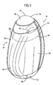
FIG. 5 is a rear perspective view of an exemplary container having a perforated shrink wrap sleeve; -
FIG. 6 illustrates an exemplary perforated shrink wrap sleeve in a front planar view (6a) and as a side view placed on a container (6b); -
FIG. 7 illustrates an exemplary perforated shrink wrap sleeve in a front planar view (7a) and as a side view placed on a container (7b); -
FIG. 8 illustrates an exemplary perforated shrink wrap sleeve in a front planar view (8a) and as a side view placed on a container (8b); -
FIG. 9 illustrates an exemplary perforated shrink wrap sleeve in a front planar view (9a) and as a side view placed on a container (9b); -
FIG. 10 illustrates an exemplary perforated shrink wrap sleeve in a front planar view (10a) and as a side view placed on a container (10b); -
FIG. 11 illustrates an exemplary perforated shrink wrap sleeve in a rear planar view; -
FIG. 12 illustrates a blank of a shrink wrap sleeve for a container; and -
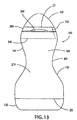
FIG. 13 is a front planar view of an exemplary container having a perforated shrink wrap sleeve. - Provided herein are embodiments for containers with perforated shrink wrapped sleeves configured to provide easy partial removal, evidence of tamper, and product labeling - even with irregularly shaped and non-symmetrical containers.
- Generally, the present embodiments illustrate a cost efficient and easy open feature for consumers to obtain full product access. As described, printed surfaces provides graphics and other types of printed information on a shrink wrapable film that can be transparent, translucent, opaque, or variations/combinations thereof. Metallic inks can also be provided to provide a silver or metallic hue. To accommodate container shape irregularities, a maximum to minimum shrinkage ratio should be at least 2:1. It is noted that various product container sizes are possible so long as the shrink wrap can be maintained thereon even after a partial band of film has been removed. Preferably, the shrink wrap film is applied as a sleeve. When a container bottom is present, it is preferably not encapsulated by the shrink wrap. On top tapered containers, the sleeve should terminate at a height on the container so that no 'puckering' would occur. For example, for the container illustrated in
FIGS. 1 and13 ; a sleeve is shown that is proportioned to reduce any evidence of a 'pucker' near the top and is not present on the bottom to allow the container to stand on its own. - The perforations of the present invention permits removal of shrink wrap above the shoulder area, which allows access to a container opening, such as a flip top cap. The shrink wrap perforations provide a tamper evident feature in that once the perforations have been breached (ruptured) and/or a partial band of film material has been removed, it is visually obvious that the container has been opened. There are several perforation patterns described within the present embodiments, though it is noted that several other variations are possible. Nevertheless, the general features of the perforation patterns can provide two separate perforation types. A first pattern can be a pair of perforations axially oriented to the sleeve to form a tab; and a second pattern can be a generally circumferential ring pattern perpendicular to the axially oriented perforations to define an upper band for removal. The axial pair of perforations can terminate at or near (e.g., 1-5 mm or 1-3 perforations) above the circumferential ring. The patterns can be configured to remove the upper band of material in one motion or by removing first a vertical tab, and then the remaining portion of the upper band. The material for the shrink wrap should be configured to withstand multiple container flexing (e.g., at least 50 times). This feature is useful for a container that contains products, such as a beverage concentrate, that require the container to be squeezed to deliver product.
- Turning now to the Figures, a container having a perforated shrink wrap sleeve is generally indicated at 10. As shown, the
container 10 can be used to dispense a liquid concentrate in a desirable manner. Thecontainer 10 can include desirable properties, for example, to consistently discharge across a range of squeezed forces, generally consistent discharge with the same force without significant dependence on the amount of liquid concentrate in the container, a substantially dripless or leak proof outlet opening, a jet that minimizes splashing when the liquid concentrate enters another liquid, and a jet that maximizes mixing between the liquid concentrate and the other liquid. Thecontainer 10 utilizes some or all of these properties while dispensing a jet of the liquid concentrate into a target container having a target liquid therein. Thecontainer 10 described herein can dispense a liquid concentrate in such a way as to enter the target liquid without substantial splashing or splatter while also causing sufficient turbulence or mixing within the target container between the liquid concentrate and the target liquid to form a generally homogenous end mixture without the use of extraneous utensils or shaking. - Referring now to
FIGs. 1 and13 , exemplary forms of thecontainer 10 are shown with at least some, and preferably all, of the above properties. The container can include a closed,first end 12 and a top,second end 14 having a hinged fliptop cap 16 secured to aback surface 23 by ahinge 44. Thefirst end 12 and the fliptop cap 16 can be connected by a generallytubular sidewall 18, which can take any suitable cross section, including any polygonal shape, any curvilinear shape, or any combination thereof, to form a container interior. Preferably, thecontainer 10 can be sized for any number of uses and can specifically be in the range of 20 to 200 cc. - Exemplary shapes of the
container 10 are illustrated inFig. 1 and13 in which thefirst end 12 acts as a secure base for thecontainer 10 to rest upon. Thesidewall 18 can generally extend upward from the base orfirst end 12 to thesecond end 14. In the form ofFIG. 1 , thecontainer 10 can have a generally 'egg' shape, where front andrear surfaces FIG. 13 , thesidewalls 18 can include a 'waist' 80 so that thecontainer 10 has an 'hourglass' shape on its front planar view. - Partially covering the
container 10, including a seam for the fliptop cap 16 can be a perforatedshrink wrap sleeve 30 having two perforation patterns including generally a pair ofvertical perforations 32 extending downward toward a horizontal (circumferential)perforation ring 34. Theshrink wrap sleeve 30 can be a polyolefin such as polyethylene terephthalate (PET), a copolymerized polyethylene terephthalate (PETG), polyethylene terephthalate glycol (PETG LV - such as sold as a film by GILBRETH, Croydon, PA, USA), polyvinyl chloride (PVC), polypropylene (PP), polyethylene (PE), and combinations thereof (or other shrinkable films). Preferably, theshrink wrap sleeve 30 is PETG. The gauge of theshrink wrap sleeve 30 can be about 40 to 55 microns, preferably about 45 microns. Shrinkage of theshrink wrap sleeve 30 can be at a shrinkage rate of about 75 percent to about85 percent (preferably about 76 percent) and have a shrink ratio selected to preferably withstand a shrinkage ratio of about 2:1. Theshrink wrap sleeve 30 can provide printed surfaces for graphics and other types of printed information or indicia on film that can be transparent, translucent, opaque, or various combinations thereof. Metallic inks can also be provided to provide a silver or metallic hue. - The
container 10 preferably has a body having a circumference variation along an axis oriented to receive theshrink wrap sleeve 30, such as a vertical axis. It is noted that circumference by the present term can mean a perimeter variation and can include circles, ellipses and other various curvilinear or geometric shaped cross-sections. By way of illustration,container 10 is configured to receive ashrink wrap sleeve 30 along a vertical axis. The portion of the container body covered byshrink wrap sleeve 30 can have a circumference variation having a greater (FIG. 1 ,18) or lesser (FIG. 13 , 80) circumference at at least one point between the shrink wraphorizontal perforation ring 34 and a shrink wrapbottom edge 20 as compared to adjacent portions of the circumference. Alternately, the portion of the container body covered by theshrink wrap sleeve 30 can have a circumference variation having a greater (FIG. 1 , 18) or lesser (FIG. 13 , 80) circumference at at least one point between the shrink wraptop edge 22 and the shrink wrapbottom edge 20 as compared to adjacent portions of the circumference. This variation can preferably range from about 5 percent to about 200 percent, and most preferably at about 100 percent. Printing on a blank 28 (FIG. 12 ) for theshrink wrap sleeve 30 can have its printing distorted to accommodate circumference variation once the shrink wrap film has been applied to the container. For example, for thecontainer 10 ofFIG. 1 having a film height of about 80 mm and placed as shown inFIG. 1 , distortion rates can be based on the following distortion percentage TABLE as follows:TABLE: Percent distortion Vertical bottle height position (mm) 135 62-80 117 50-62 110 15-50 120 0-15 - The axial circumference variation can prevent the shrink wrap seal from slipping off the container before and/or after an upper band of shrink wrap is removed to expose a container opening, such as the illustrated flip
top cap 16 and allow it to be opened for product removal. Alternately, an adhesive can be applied between thecontainer 10 body and an inner surface of theshrink wrap sleeve 30 in various configurations. - The perforation patterns can be varied but preferentially include a generally circumferential ring of perforations generally perpendicular to the
vertical perforations 32.Horizontal perforations 34 for a vertically orientedshrink wrap sleeve 30, as illustrated, generally define an upper edge of theshrink wrap sleeve 30 remaining after theupper band 38 is removed to expose the container opening for product removal. - A second aspect of the
shrink wrap sleeve 30 perforations is a pair of perforations that can run generally perpendicular to the circumferential ring of perforations. As illustrated for a vertically oriented shrink wrap sleeve, generallyvertical perforations 32 can descend from the shrink wrap top edge, 22 towards the horizontalring perforation ring 34, which is oriented below access to the fliptop cap 16. Access to fliptop cap 16 can be by way of arecession portion 52 under aledge 54. Again, many, perforation pattern variations are possible within the scope of the embodiments,FIGs. 6-10 illustrate just a sample of these types of variations. Thevertical perforations 32 can be parallel, converge, or expand as they extend (here, descend) towards thecircumferential perforation ring 34. Thevertical perforations 32 can terminate at thehorizontal ring 34 or terminate at some point above thehorizontal ring 34. - As illustrated, the vertical perforations preferably converge as they approach the
horizontal ring 34.FIG. 6a shows a perforation pattern for a shrink wrap sleeve ready for placement and heat shrinking onto thecontainer body 10.FIG. 6b illustrates theshrink wrap sleeve 30 after it has been applied to thecontainer 10 and affixed to the container by heat shrinking or other means known in the art to shrink a film on a container.FIGs. 7-10 illustrate similar views for alternate perforation pattern. It is noted that any feature or the various embodiments can be interchanged within the other embodiments, as claimed. - As to
FIG. 6 , thevertical perforations 32 converge as they approach and terminate at thehorizontal line 34.Large cuts 66 are added to the top end of thevertical perforations 32 to provide a splitting effect, a "V" 72, when applied to thecontainer 10. The pair of "V"s 72 provides apeel tab 74 to allow easy removal by a user. It is noted that as a user pulls on thepeel tab 74, avertical tab 36 is generated as the shrink wrap ruptures between the perforations. It is also noted that any ruptured patterns allow a visual inspection of the container to reveal whether the container has ever been opened or tampered with after shrink wrapping has been placed on the container. -
FIG. 7 shows a variation of the position of thelarge cut 66 bellow thetop edge 22 of theshrink wrap sleeve 30. In other words, thelarge cut 66 is placed below one or more normal perforation cuts on the top edge of thesleeve 30. In-this instance, the heat shrinking separates the shrink wrap to form a circular opening to assist in developing avertical tab 36 without forming adistinct peel tab 74. -
FIG.. 8 shows a variation of the perforation pattern by terminating thevertical perforations 32 before they reach thehorizontal ring 34. This can be defined by not placing one, two, or three perforations before it reacheshorizontal ring 34. For a container of about 80 mm in height, thisnon-perforated area 68 can have, adimension 70 of about 1 to 5 mm, and preferably about 1 to 2 mm.FIG. 9 illustrates where only one ofvertical perforations 32 has anon-perforated area 68. -
FIG. 10 illustrates ahorizontal cut 78 so that as thevertical tab 36 is removed (See, e.g.,FIG. 2 ) it separates from theshrink wrap sleeve 30 when it reaches the horizontal perforation ring. - In use, as shown in the sequence of
Figures 2-4 , a user can pinch thetab 74. and pull the shrink wrap toward thehorizontal ring 34 to form the vertical tab 36 (FIG. 1 ). Depending on the perforation pattern, a user can continuously pull thevertical tab 36 until it approaches thehorizontal ring 34, followed by a horizontal pull (FIG. 2 ) to continue the shrink wrap rupture of the horizontal ring perforations until an uppershrink wrap band 38 is removed (FIG. 3 ). Once theband 38 is removed, the lowershrink wrap band 40 remains and the product is ready for use. - The
shrink wrap 30 can be formed by a blank 28 from continuos film of PETG as shown inFIG. 12 . As shown inFIG. 12 , cutlines 50 define the size of the sleeve blank.28 as well asfold lines 48,seal area 42,copy limit 56, nolive copy 58, no legal information 60 (since that portion on the shrink wrap wilt be removed prior to use),front panel print 62, andrear panel print 64. Once a blank has been formed, the film is sealed at theseal area 42 and theperforations container 10. It is noted that there are limitless variations that are possible to forming blanks for heat shrinking onto a containers. - While preferred embodiments have been described in detail, variations and modifications can be effected within the scope of the appended claims.
Claims (15)
- A container (10), comprising:a container body having a circumference/perimeter variation along a vertical axis, a bottom surface, and a container opening having a top surface;an axially oriented shrink wrap sleeve (30)covering a portion of the body of the container(10) having a circumference variation and a portion of the container opening, a top edge (22) of the shrink wrap sleeve (30)allowing the top surface to remain exposed, and a bottom edge (20) of the shrink wrap sleeve (30)allowing the bottom surface to remain exposed;the shrink wrap sleeve (30)having a pair of generally vertical perforations (32)descending from the shrink wrap top edge (22) towards a circumferential perforation ring (34)oriented below the container opening;wherein the shrink wrap sleeve (30) covering a portion of the container body circumference variation has one of a smaller or larger circumference at at least one point between the circumferential perforation ring (34)and the bottom edge (20) as compared to adjacent portions of the circumference variation in order to prevent the shrink wrap sleeve (30) from slipping off the container(10) after removal of the portion thereof extending between the circumferential perforation ring (34)and the top edge (22);characterised in that the container opening comprises a flip top cap (16) and in that the shrink wrap sleeve (30) above the circumferential perforation ring (34)is an upper band (38) which covers a seam of the flip top cap that can be removed to expose the flip top cap (16) and allow the flip top cap (16) to be opened for product removal.
- The container(10) of claim 1, wherein the axially oriented shrink wrap sleeve (30) covering a portion of the container body circumference variation has a greater circumference at at least one point between the shrink wrap top edge (22) and the bottom edge (20).
- The container (10) of claim 1, wherein the axially oriented shrink wrap sleeve (30) covering a portion of the container body circumference variation has a greater circumference at at least one point between the shrink wrap circumferential perforation ring (34)and the bottom edge (20).
- The container (10) of claim 1, wherein the axially oriented shrink wrap sleeve (30) covering a portion of the container body circumference variation has a smaller circumference at at least one point between the circumferential perforation ring (34)and the bottom edge (20).
- The container (10) of claim 3, wherein the circumference variation is in the range of about 5 percent to about 200 percent.
- The container (10) of claim 1, wherein the generally vertical perforations (32) descending from the shrink wrap top edge (22) are progressively closer together as they approach the circumferential perforation ring (34).
- The container (10) of.claim 6, wherein the generally vertical perforations (32) descending from the shrink wrap top edge (22) terminate at the circumferential perforation ring (34).
- The container (10) of claim 6, wherein the generally vertical perforations (32)descending from the shrink wrap top edge (22) terminate at a space of about two perforations above the circumferential perforation ring (34).
- The container(10) of claim 6, wherein the generally vertical perforations (32)descending from the shrink wrap top edge (22) begin with an initial perforation cut (66), followed by relatively smaller perforation cuts, configured so that when the shrink wrap is applied to the container body, each of the larger cuts (66) forming a V shape (72)at a top of each vertical perforation (32) to define a tab (74) between the vertical perforations (32).
- The container (10) of claim 1, wherein the container body has a generally planar front and rear surface, and a seal of the shrink wrap sleeve (30)is vertically oriented along an edge of the rear surface.
- The container(10) of claim 1, wherein the shrink wrap sleeve (30)is of a gauge of between about40 to 55 microns.
- The container (10) of claim 1, wherein the shrink wrap sleeve (30)has a shrinkage rate of about 75 percent to about 85 percent.
- The container (10) of claim 1, wherein the shrink wrap sleeve (30)has a shrinkage ratio of about 2:1.
- The container (10) of claim 1, wherein the container body is squeezable to deliver a jet of product through the container opening.
- The container (10) of claim 1, wherein the container body has a pair of sidewalls (18) extending between front and rear surfaces (21,23), the sidewalls 18) converging, toward the flip top cap(16), the front and rear surfaces (21,23) each having a greater maximum width than the sidewalls (18).
Applications Claiming Priority (2)
| Application Number | Priority Date | Filing Date | Title |
|---|---|---|---|
| US37402710P | 2010-08-16 | 2010-08-16 | |
| PCT/US2011/047750 WO2012024218A1 (en) | 2010-08-16 | 2011-08-15 | Perforated shrink wrap sleeves and containers |
Publications (2)
| Publication Number | Publication Date |
|---|---|
| EP2605977A1 EP2605977A1 (en) | 2013-06-26 |
| EP2605977B1 true EP2605977B1 (en) | 2017-05-10 |
Family
ID=44504290
Family Applications (1)
| Application Number | Title | Priority Date | Filing Date |
|---|---|---|---|
| EP11746135.0A Active EP2605977B1 (en) | 2010-08-16 | 2011-08-15 | Container with perforated shrink wrap sleeve |
Country Status (12)
| Country | Link |
|---|---|
| US (2) | US8511472B2 (en) |
| EP (1) | EP2605977B1 (en) |
| JP (1) | JP6117100B2 (en) |
| CN (1) | CN103619717A (en) |
| AR (1) | AR082697A1 (en) |
| AU (2) | AU2011292173B2 (en) |
| BR (1) | BR112013003619B1 (en) |
| CA (1) | CA2807777C (en) |
| MX (1) | MX2013001751A (en) |
| RU (1) | RU2608276C2 (en) |
| SG (1) | SG187874A1 (en) |
| WO (1) | WO2012024218A1 (en) |
Cited By (5)
| Publication number | Priority date | Publication date | Assignee | Title |
|---|---|---|---|---|
| US11020561B2 (en) | 2016-04-22 | 2021-06-01 | Hollister Incorporated | Medical device package with a twist cap |
| US11103676B2 (en) | 2016-04-22 | 2021-08-31 | Hollister Incorporated | Medical device package with flip cap having a snap fit |
| US11666730B2 (en) | 2017-12-08 | 2023-06-06 | Hollister Incorporated | Package for medical device for ergonomic device removal |
| US11707599B2 (en) | 2017-02-21 | 2023-07-25 | Hollister Incorporated | Medical device package with twist-off cap |
| US11771865B2 (en) | 2017-10-25 | 2023-10-03 | Hollister Incorporated | Caps for catheter packages |
Families Citing this family (38)
| Publication number | Priority date | Publication date | Assignee | Title |
|---|---|---|---|---|
| CN101360609A (en) * | 2005-12-05 | 2009-02-04 | 生命线细胞技术公司 | Cell culture medium container assembly |
| BR112012005422B1 (en) * | 2009-09-11 | 2020-12-08 | Kraft Foods Group Brands Llc | liquid beverage concentrate and flavored liquid beverage concentrate |
| US8293299B2 (en) | 2009-09-11 | 2012-10-23 | Kraft Foods Global Brands Llc | Containers and methods for dispensing multiple doses of a concentrated liquid, and shelf stable Concentrated liquids |
| EP2611708A1 (en) * | 2010-09-02 | 2013-07-10 | Kraft Foods Group Brands LLC | Containers and methods for mixing and dispensing beverage concentrates |
| USD720622S1 (en) * | 2011-11-30 | 2015-01-06 | Tc Heartland Llc | Bottle with cap |
| USD738732S1 (en) | 2011-11-30 | 2015-09-15 | Tc Heartland Llc | Bottle with cap |
| US11013248B2 (en) | 2012-05-25 | 2021-05-25 | Kraft Foods Group Brands Llc | Shelf stable, concentrated, liquid flavorings and methods of preparing beverages with the concentrated liquid flavorings |
| USD737684S1 (en) * | 2012-08-13 | 2015-09-01 | Kraft Foods Group Brands Llc | Container |
| USD764296S1 (en) * | 2013-05-31 | 2016-08-23 | Seventh Generation, Inc. | Bottle |
| USD766088S1 (en) * | 2013-07-23 | 2016-09-13 | Heinz Weber | Container |
| USD741182S1 (en) | 2013-08-08 | 2015-10-20 | Robinsons Soft Drinks Limited | Container |
| USD749955S1 (en) * | 2013-09-10 | 2016-02-23 | The Coca-Cola Company | Bottle |
| USD749421S1 (en) * | 2013-10-01 | 2016-02-16 | Societe Des Produits Nestle S.A. | Container |
| US10145075B2 (en) | 2013-11-14 | 2018-12-04 | MedVasis, LLC | Multilayer marine wraps |
| USD757557S1 (en) * | 2013-12-17 | 2016-05-31 | Whitewave Services, Inc. | Bottle |
| USD743809S1 (en) * | 2014-05-13 | 2015-11-24 | Cool Gear International, Llc | Squeeze pouch |
| EP3152118B2 (en) | 2014-06-06 | 2022-02-16 | The Procter & Gamble Company | Faceted container |
| US20150353222A1 (en) | 2014-06-06 | 2015-12-10 | The Procter & Gamble Company | Faceted container |
| GB201410782D0 (en) * | 2014-06-17 | 2014-07-30 | Robinsons Soft Drinks Ltd | Container |
| ITMO20140341A1 (en) * | 2014-11-21 | 2016-05-21 | Cerealitalia Industrie Dolciarie Spa | CONTAINER FOR FOOD PRODUCTS |
| US20160325895A1 (en) * | 2015-05-05 | 2016-11-10 | Silgan Plastics Llc | Dispensing tube assembly with tamper indication |
| USD865526S1 (en) | 2015-12-04 | 2019-11-05 | The Procter & Gamble Company | Bottle |
| USD793239S1 (en) * | 2015-12-18 | 2017-08-01 | Nutribiotech Co., Ltd. | Container |
| CN105564807A (en) * | 2015-12-25 | 2016-05-11 | 上海钰芊容器有限公司 | Sealing method for container |
| FR3047648B1 (en) * | 2016-02-12 | 2018-02-02 | Chanel Parfums Beaute | COMPRESSIBLE DISPENSER OF A FLUID PRODUCT, ESPECIALLY A COSMETIC FLUID PRODUCT SUCH AS A CREAM |
| US10189618B2 (en) | 2016-04-15 | 2019-01-29 | Colgate-Palmolive Company | Container apparatus |
| US9902542B2 (en) * | 2016-04-15 | 2018-02-27 | Colgate-Palmolive Company | Container apparatus |
| HU4653U (en) * | 2016-06-07 | 2017-02-28 | Jozsef Rafael | Container with magnet |
| CA3031859A1 (en) * | 2016-08-26 | 2018-03-01 | Nestec S.A. | Cone sleeve with tear strip opening |
| WO2018098112A1 (en) * | 2016-11-22 | 2018-05-31 | Mccormick & Company, Incorporated | Dispenser package with flip-up or flip-out lid and method of making the same |
| USD854749S1 (en) * | 2017-01-23 | 2019-07-23 | Erin Lushefski | Ovoid-shaped cosmetic |
| USD931107S1 (en) | 2017-09-08 | 2021-09-21 | The Procter & Gamble Company | Bottle |
| IT201700122710A1 (en) * | 2017-10-27 | 2019-04-27 | Gfl S A | FLIP TOP TUBE WITH GUARANTEE SEAL |
| USD895428S1 (en) * | 2017-11-17 | 2020-09-08 | Colgate-Palmolive Company | Container |
| USD1010456S1 (en) * | 2019-05-03 | 2024-01-09 | Blue Dot Holdings, LLC | Product packaging |
| USD1020465S1 (en) * | 2020-08-11 | 2024-04-02 | Kraft Foods Group Brands Llc | Container |
| JP1688407S (en) | 2020-08-14 | 2021-06-28 | ||
| DE102021122353A1 (en) * | 2021-08-30 | 2023-03-02 | Henkel Ag & Co. Kgaa | Packaging with a PET bottle and at least two sleeves made from a shrink film |
Citations (1)
| Publication number | Priority date | Publication date | Assignee | Title |
|---|---|---|---|---|
| US20050258131A1 (en) * | 2004-05-21 | 2005-11-24 | Moser Jerry W | Easily opened tamper evident shrink band |
Family Cites Families (150)
| Publication number | Priority date | Publication date | Assignee | Title |
|---|---|---|---|---|
| US2954139A (en) | 1956-12-12 | 1960-09-27 | Celon Company | Tear strip for seals |
| NL136193C (en) | 1963-03-19 | |||
| US3733002A (en) * | 1970-10-12 | 1973-05-15 | M Fujio | Sealed container |
| US3746201A (en) | 1970-10-30 | 1973-07-17 | M Fujio | Heat-shrinkable capsule |
| US3873018A (en) | 1973-02-20 | 1975-03-25 | Minnesota Mining & Mfg | Easily rupturable band of tape |
| US4000824A (en) | 1975-07-24 | 1977-01-04 | Minnesota Mining And Manufacturing Company | Tape closures |
| US4124151A (en) | 1976-11-22 | 1978-11-07 | Polytop Corporation | Toggle type dispensing closure |
| USD265060S (en) | 1979-09-13 | 1982-06-22 | The Clorox Company | Dispensing closure |
| US4358032A (en) | 1980-12-24 | 1982-11-09 | Libit Sidney M | Snap container closure |
| USD282441S (en) | 1983-06-29 | 1986-02-04 | Shiseido Co., Ltd. | Bottle |
| US4538740A (en) * | 1983-12-27 | 1985-09-03 | Fantasy Flavors, Inc. | Tamper resistant closure |
| USD292882S (en) | 1985-03-18 | 1987-11-24 | Pittway Corporation | Dispensing container closure |
| US4758456A (en) | 1987-03-18 | 1988-07-19 | Morgan Adhesives Company | Bottle seal |
| DE8704836U1 (en) * | 1987-03-25 | 1987-06-11 | Folien Fischer Ag, Dottikon, Ch | |
| USD322220S (en) | 1988-05-13 | 1991-12-10 | Henkel Kommanditgesellschaft Auf Aktien | Closure for bottle |
| USD332749S (en) | 1988-05-13 | 1993-01-26 | Henkel Kommanditgesellschaft Auf Aktien | Combined bottle and cap |
| USD316369S (en) | 1988-05-31 | 1991-04-23 | Sterling Drug Inc. | Combined bottle and measuring cup cover |
| AU105131S (en) | 1988-06-20 | 1989-09-18 | Unilever Plc | Container with cap |
| USD320746S (en) | 1988-07-01 | 1991-10-15 | Bolen Jr Robert J | Closure |
| USD317869S (en) | 1989-04-20 | 1991-07-02 | Chesebrough-Pond's Inc. | Bottle cap |
| CH678938A5 (en) * | 1989-07-14 | 1991-11-29 | Sandherr Packungen Ag | |
| US5038974A (en) | 1989-08-14 | 1991-08-13 | Dacosta Harry | Combined food container and dispenser |
| US4976798A (en) | 1990-01-12 | 1990-12-11 | Shibuya America Corporation | Method of applying a plastic wrap to a contoured container |
| USD336614S (en) | 1990-08-24 | 1993-06-22 | Colgate-Palmolive Company | Combined bottle and cap |
| NL9002569A (en) * | 1990-11-26 | 1992-06-16 | Bernardus Johannes Martinus Ma | PACKAGING FOR PLANTS OR FLOWERS PLACED IN A POT-HOLDER. |
| AU116305S (en) | 1992-02-27 | 1993-02-09 | Reckitt Benckiser France | Container |
| US5292018A (en) | 1992-07-07 | 1994-03-08 | Travisano Frank P | Tamper evident seal and system |
| JP3235227B2 (en) | 1992-10-30 | 2001-12-04 | ソニー株式会社 | Overlap film and lapping method using the overlap film |
| USD347389S (en) | 1993-01-15 | 1994-05-31 | Colgate-Palmolive Company | Combined bottle and cap |
| CA2094630A1 (en) * | 1993-01-19 | 1994-07-20 | John Leroy Herzberg | Facial tissue pocket pack |
| JPH074377U (en) | 1993-06-21 | 1995-01-24 | 富士写真フイルム株式会社 | Package |
| GB9321755D0 (en) * | 1993-10-21 | 1993-12-15 | Wellcome Found | Bottle with tamper evident wrapping |
| US5605230A (en) | 1994-10-11 | 1997-02-25 | Elr, Inc. | Sealed label having anti-counterfeit construction |
| USD382803S (en) | 1996-08-20 | 1997-08-26 | L'oreal S.A. | Combined bottle and cap |
| US6296129B1 (en) * | 1996-09-16 | 2001-10-02 | American Fuji Seal, Inc. | Method for shrink-wrapping containers and articles obtained thereby |
| USD391855S (en) | 1997-01-23 | 1998-03-10 | FWJ Plastics, Inc. | Bottle |
| USD387673S (en) | 1997-02-04 | 1997-12-16 | Colgate-Palmolive Company | Container |
| USD419455S (en) | 1998-03-25 | 2000-01-25 | Abbott Laboratories | Liquid container |
| FR2778639B1 (en) | 1998-05-18 | 2000-07-28 | Valois Sa | SAMPLE TYPE SPRAYING DEVICE |
| AU139268S (en) | 1998-06-02 | 1999-12-15 | Reckitt Benckiser Uk Ltd | Container |
| FR2781770B1 (en) | 1998-07-30 | 2000-10-13 | Valois Sa | FLUID PRODUCT SAMPLE |
| USD413265S (en) | 1998-12-11 | 1999-08-31 | Bomatic, Inc. | Square milk bottle |
| US6385878B1 (en) * | 1999-02-09 | 2002-05-14 | Stephen Key Design, Llc | Rotatable label system including tamper-evident feature and method for constructing same |
| USD427073S (en) | 1999-02-22 | 2000-06-27 | Owens-Brockway Plastic Products Inc. | Combined container and closure |
| ES2366081T3 (en) | 1999-08-17 | 2011-10-17 | Santen Pharmaceutical Co., Ltd | SEALING LABEL. |
| USD463747S1 (en) | 1999-09-09 | 2002-10-01 | Johnson & Johnson Industria E. Comercio Ltda. | Container-lid assembly |
| USD457437S1 (en) | 1999-11-02 | 2002-05-21 | The Coca-Cola Company | Bottle with closure |
| USD459659S1 (en) * | 2000-03-10 | 2002-07-02 | Lg Household & Health Care Ltd. | Shampoo bottle |
| USD438459S1 (en) | 2000-03-20 | 2001-03-06 | Henkel Kommanditgesellschaft Auf Aktien | Cream and deodorant dispenser container |
| USD447953S1 (en) | 2000-07-14 | 2001-09-18 | 3M Innovative Properties Company | Container with cap |
| USD510029S1 (en) | 2001-02-28 | 2005-09-27 | Henkel Kommanditgesellschaft Auf Aktien | Container |
| US6783035B2 (en) | 2001-07-19 | 2004-08-31 | Valois S.A.S. | Fluid product dispenser |
| USD463744S1 (en) | 2001-11-08 | 2002-10-01 | Owens-Illinois Closure Inc. | Closure |
| USD471819S1 (en) | 2002-01-10 | 2003-03-18 | The Procter & Gamble Company | Bottle with cup |
| USD471818S1 (en) | 2002-04-19 | 2003-03-18 | Heinz Weber | Bottle and cap |
| FR2841223B1 (en) * | 2002-06-19 | 2004-10-15 | Sleever Int | PACKAGING FOR OBJECTS (S) OF HEAT SHRINKABLE MATERIAL WITH ESSENTIALLY SMOOTH INTERNAL OR EXTERNAL SIDE |
| USD504613S1 (en) | 2002-07-19 | 2005-05-03 | Pichiney Plastic Packaging, Inc. | Cap for a tubular dispenser |
| CA101916S (en) | 2002-08-08 | 2003-12-15 | Unilever Plc | Bottle |
| USD481636S1 (en) | 2002-09-04 | 2003-11-04 | Colgate-Palmolive Company | Dispenser |
| AU2003284344A1 (en) * | 2002-10-25 | 2004-05-25 | National Label Company | Labeling apparatus and method of making same |
| USD482286S1 (en) | 2002-12-02 | 2003-11-18 | S. C. Johnson & Son, Inc. | Dispensing container |
| JP2004219621A (en) * | 2003-01-14 | 2004-08-05 | Gunze Ltd | Label for container and container with the label attached thereto |
| USD498415S1 (en) | 2003-01-17 | 2004-11-16 | The Procter & Gamble Company | Container |
| US6779689B2 (en) | 2003-01-21 | 2004-08-24 | Unilever Home & Personal Care Usa, Division Of Conopco, Inc. | Ovaloid dispensing container |
| US6837405B2 (en) | 2003-01-21 | 2005-01-04 | Unilever Home & Personal Care Usa, Division Of Conopco, Inc. | Ovaloid bottle with overcap |
| USD486065S1 (en) | 2003-01-31 | 2004-02-03 | Unilever Home & Personal Care Usa, Division Of Conopco, Inc. | Bottle |
| USD529810S1 (en) | 2003-04-29 | 2006-10-10 | Unilever Home & Personal Care Usa, Division Of Conopco, Inc. | Bottle |
| CN2637367Y (en) * | 2003-07-25 | 2004-09-01 | 上海万汇塑料包装容器有限公司 | Lid-turnover container |
| FR2858301B1 (en) * | 2003-07-29 | 2006-05-26 | Airsec | WATERPROOF DESSICATIVE CONTAINER FOR PACKAGING AMBIENT HUMIDITY-SENSITIVE PRODUCTS |
| US20050035081A1 (en) | 2003-08-12 | 2005-02-17 | Fitch Russell M. | Tamper resistant beverage bottle |
| ATE401255T1 (en) * | 2003-09-05 | 2008-08-15 | Csp Technologies Inc | CHILD-PROOF SAFETY LATCH ON OR FOR CONTAINERS |
| USD537721S1 (en) | 2003-09-09 | 2007-03-06 | Megasol Cosmetic Gmbh | Flask |
| US7322493B2 (en) * | 2003-10-09 | 2008-01-29 | Polytop Corporation | Dispensing closure having complete peripheral seal |
| US7147131B2 (en) | 2003-12-05 | 2006-12-12 | Nestec S.A. | Method and system for dispensing hot and cold beverages from liquid concentrates |
| JP4187671B2 (en) * | 2004-03-04 | 2008-11-26 | レンゴー株式会社 | Plastic label |
| USD526204S1 (en) | 2004-03-11 | 2006-08-08 | Shb Gmbh & Co Kg | Bottle |
| AU300702S (en) | 2004-03-27 | 2005-02-16 | Unilever Plc | Bottle |
| USD528004S1 (en) | 2004-03-27 | 2006-09-12 | Unilever Home & Personal Care Usa, Division Of Conopco, Inc. | Portion of a bottle |
| USD529811S1 (en) | 2004-03-27 | 2006-10-10 | Unilever Home & Personal Care Usa, Division Of Conopco, Inc. | Bottle |
| USD525135S1 (en) | 2004-04-27 | 2006-07-18 | Db Design Gmbh | Cosmetic container |
| USD527641S1 (en) | 2004-04-27 | 2006-09-05 | Db Design Gmbh | Cosmetic container |
| CN2709350Y (en) * | 2004-05-25 | 2005-07-13 | 黄锦强 | Oral liquid bottle cap |
| USD527640S1 (en) | 2004-07-22 | 2006-09-05 | Colgate-Palmolive Company | Container and cap |
| US7661352B2 (en) | 2004-08-31 | 2010-02-16 | Nestec S.A. | Method and system for in-cup dispensing, mixing and foaming hot and cold beverages from liquid concentrates |
| USD525872S1 (en) | 2004-09-20 | 2006-08-01 | Unilever Home & Personal Care Usa, Division Of Conopco, Inc. | Bottle for dispensing cosmetics |
| USD525873S1 (en) | 2004-09-20 | 2006-08-01 | Unilever Home & Personal Care Usa, Division Of Conopco, Inc. | Container with flip-top lid |
| USD532301S1 (en) | 2004-10-19 | 2006-11-21 | Lumson S.P.A. | Spray stopper |
| USD538668S1 (en) | 2005-01-20 | 2007-03-20 | The Procter & Gamble Company | Container |
| JP2006306442A (en) * | 2005-04-28 | 2006-11-09 | Toppan Printing Co Ltd | Unsealing facilitating and label peeling facilitating glass bottle |
| USD543861S1 (en) | 2005-07-13 | 2007-06-05 | Conopco, Inc. | Bottle |
| USD542140S1 (en) | 2005-07-13 | 2007-05-08 | Conopco, Inc. | Bottle with cap |
| US20110204049A1 (en) * | 2005-07-22 | 2011-08-25 | Weder Donald E | Collapsible and/or erectable substantially egg-shaped container |
| USD542141S1 (en) | 2005-07-26 | 2007-05-08 | Conopco, Inc. | Combined bottle and cap |
| US7815075B2 (en) | 2005-07-28 | 2010-10-19 | Joseph S Kanfer | Personal squeeze bottle dispenser |
| USD563789S1 (en) | 2005-09-22 | 2008-03-11 | The Procter & Gamble Company | Container |
| EP1779933A1 (en) | 2005-10-26 | 2007-05-02 | The Procter and Gamble Company | Dispenser for a liquid |
| US20070095784A1 (en) | 2005-10-28 | 2007-05-03 | Conopco, Inc. | Package for liquid laundry products |
| USD536975S1 (en) | 2005-11-18 | 2007-02-20 | Seaquist Closures Foreign, Inc. | Closure |
| USD563226S1 (en) | 2005-11-18 | 2008-03-04 | The Procter & Gamble Company | Container |
| USD544351S1 (en) | 2005-12-28 | 2007-06-12 | Access Business Group International Llc | Container |
| USD574246S1 (en) | 2006-02-17 | 2008-08-05 | The Procter & Gamble Company | Container and closure |
| USD565959S1 (en) | 2006-03-24 | 2008-04-08 | Reckitt Benckiser Inc. | Bottle with cap |
| USD543115S1 (en) | 2006-04-24 | 2007-05-22 | Conopco, Inc. | Combined bottle and cap |
| USD540176S1 (en) | 2006-04-24 | 2007-04-10 | Conopco, Inc. | Combined bottle and cap |
| US8608001B2 (en) * | 2006-04-25 | 2013-12-17 | Berry Plastics Corporation | Mold-in-place two shot seal |
| USD584159S1 (en) | 2006-04-25 | 2009-01-06 | Conopco, Inc. | Container with flip-top lid |
| US7976234B2 (en) | 2006-04-28 | 2011-07-12 | James Alexander Corporation | Multi-chambered dispenser and process |
| USD547190S1 (en) | 2006-05-23 | 2007-07-24 | Gk Packaging Inc. | Bottle |
| USD581794S1 (en) | 2006-08-25 | 2008-12-02 | Conopco, Inc. | Bottle |
| CZ17042U1 (en) * | 2006-08-31 | 2006-11-27 | Dlouhý@Pavel | Beverage bottle with advertising object |
| USD580767S1 (en) | 2006-09-08 | 2008-11-18 | Conopco, Inc. | Bottle |
| USD577592S1 (en) | 2006-09-25 | 2008-09-30 | Sd Ip Holding Company | Bottle |
| USD578003S1 (en) | 2006-10-24 | 2008-10-07 | The Procter & Gamble Company | Bottle and cap |
| USD580762S1 (en) | 2006-11-20 | 2008-11-18 | Mccormick & Company, Inc. | Non-drip spout |
| USD590259S1 (en) | 2007-03-01 | 2009-04-14 | S.C. Johnson & Son, Inc. | Inverted bottle with cap |
| USD585289S1 (en) | 2007-03-28 | 2009-01-27 | Colgate-Palmolive Company | Container |
| USD554515S1 (en) | 2007-03-28 | 2007-11-06 | Colgate-Palmolive Company | Container |
| USD585290S1 (en) | 2007-03-28 | 2009-01-27 | Colgate-Palmolive Company | Container |
| JP2008285195A (en) * | 2007-05-17 | 2008-11-27 | Toppan Printing Co Ltd | Shrink label and object having the label attached |
| CA123537S (en) | 2007-06-18 | 2008-09-03 | Unilever Plc | Jar |
| USD588460S1 (en) | 2007-07-13 | 2009-03-17 | The Procter & Gamble Company | Bottle |
| JP5280042B2 (en) * | 2007-11-20 | 2013-09-04 | 株式会社フジシールインターナショナル | Labeled containers and packaging labels |
| USD598752S1 (en) | 2007-11-20 | 2009-08-25 | Mccormick & Company, Incorporated | Non-drip spout |
| USD588459S1 (en) | 2008-01-08 | 2009-03-17 | The Procter & Gamble Company | Bottle |
| USD588462S1 (en) | 2008-01-08 | 2009-03-17 | The Procter & Gamble Company | Bottle |
| USD592957S1 (en) | 2008-01-08 | 2009-05-26 | The Procter & Gamble Company | Bottle |
| USD601899S1 (en) | 2008-01-08 | 2009-10-13 | The Procter & Gamble Company | Bottle |
| USD588461S1 (en) | 2008-01-08 | 2009-03-17 | The Procter & Gamble Company | Bottle |
| USD573031S1 (en) | 2008-02-07 | 2008-07-15 | Kjeld Hestehave | Bottle |
| USD591599S1 (en) | 2008-02-20 | 2009-05-05 | Conopco, Inc. | Container |
| USD605945S1 (en) | 2008-03-26 | 2009-12-15 | The Procter & Gamble Company | Bottle |
| AU323031S (en) | 2008-04-18 | 2008-12-11 | Unilever Plc | Container |
| USD587117S1 (en) | 2008-05-06 | 2009-02-24 | Colgate-Palmolive Company | Container and closure |
| USD595138S1 (en) | 2008-07-08 | 2009-06-30 | The Procter & Gamble Company | Bottle with cap |
| JP5282243B2 (en) * | 2008-09-22 | 2013-09-04 | 株式会社フジシール | Container with shrink label |
| USD608648S1 (en) | 2008-12-22 | 2010-01-26 | The Dial Corporation | Bottle |
| USD608645S1 (en) | 2009-01-30 | 2010-01-26 | Method Products, Inc. | Bottle |
| USD610022S1 (en) | 2009-02-27 | 2010-02-16 | Gojo Industries, Inc. | Hand held dispenser |
| US9309029B2 (en) * | 2009-03-05 | 2016-04-12 | Multisorb Technologies, Inc. | Method of molding a high moisture barrier and self-desiccating container with living hinge |
| USD605512S1 (en) | 2009-03-20 | 2009-12-08 | Heinz Weber | Closure for container |
| USD629303S1 (en) | 2009-06-09 | 2010-12-21 | Colgate-Palmolive Company | Container |
| USD624424S1 (en) | 2009-06-10 | 2010-09-28 | Conopco, Inc. | Bottle |
| USD614488S1 (en) | 2009-06-23 | 2010-04-27 | The J.M. Smucker Company | Dispensing closure |
| USD628488S1 (en) | 2009-07-27 | 2010-12-07 | Schering-Plough Healthcare Products, Inc. | Bottle |
| USD644106S1 (en) | 2009-10-03 | 2011-08-30 | Conopco, Inc. | Container |
| USD628490S1 (en) | 2010-01-14 | 2010-12-07 | Sato Pharmaceutical Co., Ltd. | Eye drop container |
| USD638715S1 (en) | 2010-04-01 | 2011-05-31 | Kraft Foods Global Brands Llc | Container |
| USD638714S1 (en) | 2010-04-01 | 2011-05-31 | Kraft Foods Global Brands Llc | Container |
| USD638713S1 (en) | 2010-08-19 | 2011-05-31 | Kraft Foods Global Brands Llc | Container |
| USD636267S1 (en) | 2010-07-06 | 2011-04-19 | Shiseido Co., Ltd. | Combined bottle and cap |
-
2011
- 2011-08-15 WO PCT/US2011/047750 patent/WO2012024218A1/en active Application Filing
- 2011-08-15 SG SG2013011630A patent/SG187874A1/en unknown
- 2011-08-15 CN CN201180050016.8A patent/CN103619717A/en active Pending
- 2011-08-15 CA CA2807777A patent/CA2807777C/en active Active
- 2011-08-15 AR ARP110102967A patent/AR082697A1/en active IP Right Grant
- 2011-08-15 EP EP11746135.0A patent/EP2605977B1/en active Active
- 2011-08-15 AU AU2011292173A patent/AU2011292173B2/en active Active
- 2011-08-15 BR BR112013003619-2A patent/BR112013003619B1/en active IP Right Grant
- 2011-08-15 RU RU2013106422A patent/RU2608276C2/en active
- 2011-08-15 MX MX2013001751A patent/MX2013001751A/en unknown
- 2011-08-15 JP JP2013524908A patent/JP6117100B2/en active Active
-
2012
- 2012-04-30 US US13/460,633 patent/US8511472B2/en not_active Expired - Fee Related
-
2013
- 2013-07-19 US US13/946,896 patent/US20130299516A1/en not_active Abandoned
-
2016
- 2016-04-13 AU AU2016202329A patent/AU2016202329B2/en active Active
Patent Citations (1)
| Publication number | Priority date | Publication date | Assignee | Title |
|---|---|---|---|---|
| US20050258131A1 (en) * | 2004-05-21 | 2005-11-24 | Moser Jerry W | Easily opened tamper evident shrink band |
Cited By (5)
| Publication number | Priority date | Publication date | Assignee | Title |
|---|---|---|---|---|
| US11020561B2 (en) | 2016-04-22 | 2021-06-01 | Hollister Incorporated | Medical device package with a twist cap |
| US11103676B2 (en) | 2016-04-22 | 2021-08-31 | Hollister Incorporated | Medical device package with flip cap having a snap fit |
| US11707599B2 (en) | 2017-02-21 | 2023-07-25 | Hollister Incorporated | Medical device package with twist-off cap |
| US11771865B2 (en) | 2017-10-25 | 2023-10-03 | Hollister Incorporated | Caps for catheter packages |
| US11666730B2 (en) | 2017-12-08 | 2023-06-06 | Hollister Incorporated | Package for medical device for ergonomic device removal |
Also Published As
| Publication number | Publication date |
|---|---|
| AU2011292173A8 (en) | 2013-03-21 |
| CA2807777A1 (en) | 2012-02-23 |
| AU2011292173A1 (en) | 2013-03-07 |
| US20130299516A1 (en) | 2013-11-14 |
| AR082697A1 (en) | 2012-12-26 |
| US8511472B2 (en) | 2013-08-20 |
| JP6117100B2 (en) | 2017-04-19 |
| BR112013003619A2 (en) | 2016-08-23 |
| CA2807777C (en) | 2018-04-03 |
| RU2608276C2 (en) | 2017-01-17 |
| CN103619717A (en) | 2014-03-05 |
| WO2012024218A1 (en) | 2012-02-23 |
| AU2016202329A1 (en) | 2016-05-05 |
| MX2013001751A (en) | 2013-06-05 |
| JP2013537506A (en) | 2013-10-03 |
| AU2011292173B2 (en) | 2016-02-11 |
| SG187874A1 (en) | 2013-03-28 |
| US20120211526A1 (en) | 2012-08-23 |
| RU2013106422A (en) | 2014-09-27 |
| AU2016202329B2 (en) | 2017-09-14 |
| EP2605977A1 (en) | 2013-06-26 |
| BR112013003619B1 (en) | 2020-05-26 |
Similar Documents
| Publication | Publication Date | Title |
|---|---|---|
| EP2605977B1 (en) | Container with perforated shrink wrap sleeve | |
| US20210107707A1 (en) | Novel tamper evident containers | |
| US5957584A (en) | Flexible tamper-evident package with integral fitment | |
| US10279953B2 (en) | Container seal | |
| SK18432000A3 (en) | Meal kit | |
| JPH05338648A (en) | Opening apparatus and manufacture thereof | |
| US9656780B1 (en) | Container seal with dual tabs | |
| EP3124392B1 (en) | Overcap having means which facilitate the opening of a container and the subsequent direct consumption of the content thereof | |
| JP2007045425A (en) | Container | |
| JP6888335B2 (en) | Paper container | |
| WO2004099008A2 (en) | Improved neck band using straight-tear film | |
| JP2003237741A (en) | Shrink package | |
| JP2006306431A (en) | Shrinkable film | |
| JP4726326B2 (en) | Manufacturing method of bag-shaped container with a stopper, and bag-shaped container with a stopper | |
| JP7393936B2 (en) | Labeled containers and beverage products | |
| US20230134697A1 (en) | Multi-use, reusable, spill proof package for fluids without a removable or separable closure | |
| JP2006206108A (en) | Foolproof packaging | |
| CN104169185A (en) | Sealing disc for induction sealing of container |
Legal Events
| Date | Code | Title | Description |
|---|---|---|---|
| PUAI | Public reference made under article 153(3) epc to a published international application that has entered the european phase |
Free format text: ORIGINAL CODE: 0009012 |
|
| 17P | Request for examination filed |
Effective date: 20130208 |
|
| AK | Designated contracting states |
Kind code of ref document: A1 Designated state(s): AL AT BE BG CH CY CZ DE DK EE ES FI FR GB GR HR HU IE IS IT LI LT LU LV MC MK MT NL NO PL PT RO RS SE SI SK SM TR |
|
| RIN1 | Information on inventor provided before grant (corrected) |
Inventor name: LUCISANO, KATHERINE Inventor name: DE CLEIR, PIARAS VALDIS Inventor name: DUPUIS, GLEN A. |
|
| DAX | Request for extension of the european patent (deleted) | ||
| 17Q | First examination report despatched |
Effective date: 20151218 |
|
| GRAP | Despatch of communication of intention to grant a patent |
Free format text: ORIGINAL CODE: EPIDOSNIGR1 |
|
| INTG | Intention to grant announced |
Effective date: 20160712 |
|
| GRAJ | Information related to disapproval of communication of intention to grant by the applicant or resumption of examination proceedings by the epo deleted |
Free format text: ORIGINAL CODE: EPIDOSDIGR1 |
|
| GRAP | Despatch of communication of intention to grant a patent |
Free format text: ORIGINAL CODE: EPIDOSNIGR1 |
|
| INTG | Intention to grant announced |
Effective date: 20161201 |
|
| GRAS | Grant fee paid |
Free format text: ORIGINAL CODE: EPIDOSNIGR3 |
|
| GRAA | (expected) grant |
Free format text: ORIGINAL CODE: 0009210 |
|
| AK | Designated contracting states |
Kind code of ref document: B1 Designated state(s): AL AT BE BG CH CY CZ DE DK EE ES FI FR GB GR HR HU IE IS IT LI LT LU LV MC MK MT NL NO PL PT RO RS SE SI SK SM TR |
|
| REG | Reference to a national code |
Ref country code: GB Ref legal event code: FG4D |
|
| REG | Reference to a national code |
Ref country code: AT Ref legal event code: REF Ref document number: 892063 Country of ref document: AT Kind code of ref document: T Effective date: 20170515 Ref country code: CH Ref legal event code: EP |
|
| REG | Reference to a national code |
Ref country code: IE Ref legal event code: FG4D |
|
| REG | Reference to a national code |
Ref country code: NL Ref legal event code: FP |
|
| REG | Reference to a national code |
Ref country code: DE Ref legal event code: R096 Ref document number: 602011037826 Country of ref document: DE |
|
| REG | Reference to a national code |
Ref country code: FR Ref legal event code: PLFP Year of fee payment: 7 |
|
| REG | Reference to a national code |
Ref country code: LT Ref legal event code: MG4D |
|
| REG | Reference to a national code |
Ref country code: AT Ref legal event code: MK05 Ref document number: 892063 Country of ref document: AT Kind code of ref document: T Effective date: 20170510 |
|
| PG25 | Lapsed in a contracting state [announced via postgrant information from national office to epo] |
Ref country code: ES Free format text: LAPSE BECAUSE OF FAILURE TO SUBMIT A TRANSLATION OF THE DESCRIPTION OR TO PAY THE FEE WITHIN THE PRESCRIBED TIME-LIMIT Effective date: 20170510 Ref country code: LT Free format text: LAPSE BECAUSE OF FAILURE TO SUBMIT A TRANSLATION OF THE DESCRIPTION OR TO PAY THE FEE WITHIN THE PRESCRIBED TIME-LIMIT Effective date: 20170510 Ref country code: GR Free format text: LAPSE BECAUSE OF FAILURE TO SUBMIT A TRANSLATION OF THE DESCRIPTION OR TO PAY THE FEE WITHIN THE PRESCRIBED TIME-LIMIT Effective date: 20170811 Ref country code: HR Free format text: LAPSE BECAUSE OF FAILURE TO SUBMIT A TRANSLATION OF THE DESCRIPTION OR TO PAY THE FEE WITHIN THE PRESCRIBED TIME-LIMIT Effective date: 20170510 Ref country code: FI Free format text: LAPSE BECAUSE OF FAILURE TO SUBMIT A TRANSLATION OF THE DESCRIPTION OR TO PAY THE FEE WITHIN THE PRESCRIBED TIME-LIMIT Effective date: 20170510 Ref country code: NO Free format text: LAPSE BECAUSE OF FAILURE TO SUBMIT A TRANSLATION OF THE DESCRIPTION OR TO PAY THE FEE WITHIN THE PRESCRIBED TIME-LIMIT Effective date: 20170810 Ref country code: AT Free format text: LAPSE BECAUSE OF FAILURE TO SUBMIT A TRANSLATION OF THE DESCRIPTION OR TO PAY THE FEE WITHIN THE PRESCRIBED TIME-LIMIT Effective date: 20170510 |
|
| PG25 | Lapsed in a contracting state [announced via postgrant information from national office to epo] |
Ref country code: SE Free format text: LAPSE BECAUSE OF FAILURE TO SUBMIT A TRANSLATION OF THE DESCRIPTION OR TO PAY THE FEE WITHIN THE PRESCRIBED TIME-LIMIT Effective date: 20170510 Ref country code: RS Free format text: LAPSE BECAUSE OF FAILURE TO SUBMIT A TRANSLATION OF THE DESCRIPTION OR TO PAY THE FEE WITHIN THE PRESCRIBED TIME-LIMIT Effective date: 20170510 Ref country code: LV Free format text: LAPSE BECAUSE OF FAILURE TO SUBMIT A TRANSLATION OF THE DESCRIPTION OR TO PAY THE FEE WITHIN THE PRESCRIBED TIME-LIMIT Effective date: 20170510 Ref country code: BG Free format text: LAPSE BECAUSE OF FAILURE TO SUBMIT A TRANSLATION OF THE DESCRIPTION OR TO PAY THE FEE WITHIN THE PRESCRIBED TIME-LIMIT Effective date: 20170810 Ref country code: IS Free format text: LAPSE BECAUSE OF FAILURE TO SUBMIT A TRANSLATION OF THE DESCRIPTION OR TO PAY THE FEE WITHIN THE PRESCRIBED TIME-LIMIT Effective date: 20170910 Ref country code: PL Free format text: LAPSE BECAUSE OF FAILURE TO SUBMIT A TRANSLATION OF THE DESCRIPTION OR TO PAY THE FEE WITHIN THE PRESCRIBED TIME-LIMIT Effective date: 20170510 |
|
| PG25 | Lapsed in a contracting state [announced via postgrant information from national office to epo] |
Ref country code: SK Free format text: LAPSE BECAUSE OF FAILURE TO SUBMIT A TRANSLATION OF THE DESCRIPTION OR TO PAY THE FEE WITHIN THE PRESCRIBED TIME-LIMIT Effective date: 20170510 Ref country code: CZ Free format text: LAPSE BECAUSE OF FAILURE TO SUBMIT A TRANSLATION OF THE DESCRIPTION OR TO PAY THE FEE WITHIN THE PRESCRIBED TIME-LIMIT Effective date: 20170510 Ref country code: EE Free format text: LAPSE BECAUSE OF FAILURE TO SUBMIT A TRANSLATION OF THE DESCRIPTION OR TO PAY THE FEE WITHIN THE PRESCRIBED TIME-LIMIT Effective date: 20170510 Ref country code: RO Free format text: LAPSE BECAUSE OF FAILURE TO SUBMIT A TRANSLATION OF THE DESCRIPTION OR TO PAY THE FEE WITHIN THE PRESCRIBED TIME-LIMIT Effective date: 20170510 Ref country code: DK Free format text: LAPSE BECAUSE OF FAILURE TO SUBMIT A TRANSLATION OF THE DESCRIPTION OR TO PAY THE FEE WITHIN THE PRESCRIBED TIME-LIMIT Effective date: 20170510 |
|
| REG | Reference to a national code |
Ref country code: DE Ref legal event code: R097 Ref document number: 602011037826 Country of ref document: DE |
|
| PG25 | Lapsed in a contracting state [announced via postgrant information from national office to epo] |
Ref country code: SM Free format text: LAPSE BECAUSE OF FAILURE TO SUBMIT A TRANSLATION OF THE DESCRIPTION OR TO PAY THE FEE WITHIN THE PRESCRIBED TIME-LIMIT Effective date: 20170510 |
|
| PLBE | No opposition filed within time limit |
Free format text: ORIGINAL CODE: 0009261 |
|
| STAA | Information on the status of an ep patent application or granted ep patent |
Free format text: STATUS: NO OPPOSITION FILED WITHIN TIME LIMIT |
|
| REG | Reference to a national code |
Ref country code: CH Ref legal event code: PL |
|
| PG25 | Lapsed in a contracting state [announced via postgrant information from national office to epo] |
Ref country code: MC Free format text: LAPSE BECAUSE OF FAILURE TO SUBMIT A TRANSLATION OF THE DESCRIPTION OR TO PAY THE FEE WITHIN THE PRESCRIBED TIME-LIMIT Effective date: 20170510 |
|
| 26N | No opposition filed |
Effective date: 20180213 |
|
| PG25 | Lapsed in a contracting state [announced via postgrant information from national office to epo] |
Ref country code: CH Free format text: LAPSE BECAUSE OF NON-PAYMENT OF DUE FEES Effective date: 20170831 Ref country code: LI Free format text: LAPSE BECAUSE OF NON-PAYMENT OF DUE FEES Effective date: 20170831 |
|
| REG | Reference to a national code |
Ref country code: IE Ref legal event code: MM4A |
|
| PG25 | Lapsed in a contracting state [announced via postgrant information from national office to epo] |
Ref country code: SI Free format text: LAPSE BECAUSE OF FAILURE TO SUBMIT A TRANSLATION OF THE DESCRIPTION OR TO PAY THE FEE WITHIN THE PRESCRIBED TIME-LIMIT Effective date: 20170510 |
|
| REG | Reference to a national code |
Ref country code: BE Ref legal event code: MM Effective date: 20170831 |
|
| PG25 | Lapsed in a contracting state [announced via postgrant information from national office to epo] |
Ref country code: LU Free format text: LAPSE BECAUSE OF NON-PAYMENT OF DUE FEES Effective date: 20170815 |
|
| PG25 | Lapsed in a contracting state [announced via postgrant information from national office to epo] |
Ref country code: IE Free format text: LAPSE BECAUSE OF NON-PAYMENT OF DUE FEES Effective date: 20170815 |
|
| REG | Reference to a national code |
Ref country code: FR Ref legal event code: PLFP Year of fee payment: 8 |
|
| PG25 | Lapsed in a contracting state [announced via postgrant information from national office to epo] |
Ref country code: BE Free format text: LAPSE BECAUSE OF NON-PAYMENT OF DUE FEES Effective date: 20170831 |
|
| PG25 | Lapsed in a contracting state [announced via postgrant information from national office to epo] |
Ref country code: MT Free format text: LAPSE BECAUSE OF NON-PAYMENT OF DUE FEES Effective date: 20170815 |
|
| PG25 | Lapsed in a contracting state [announced via postgrant information from national office to epo] |
Ref country code: HU Free format text: LAPSE BECAUSE OF FAILURE TO SUBMIT A TRANSLATION OF THE DESCRIPTION OR TO PAY THE FEE WITHIN THE PRESCRIBED TIME-LIMIT; INVALID AB INITIO Effective date: 20110815 |
|
| PG25 | Lapsed in a contracting state [announced via postgrant information from national office to epo] |
Ref country code: CY Free format text: LAPSE BECAUSE OF NON-PAYMENT OF DUE FEES Effective date: 20170510 |
|
| PG25 | Lapsed in a contracting state [announced via postgrant information from national office to epo] |
Ref country code: MK Free format text: LAPSE BECAUSE OF FAILURE TO SUBMIT A TRANSLATION OF THE DESCRIPTION OR TO PAY THE FEE WITHIN THE PRESCRIBED TIME-LIMIT Effective date: 20170510 |
|
| PG25 | Lapsed in a contracting state [announced via postgrant information from national office to epo] |
Ref country code: TR Free format text: LAPSE BECAUSE OF FAILURE TO SUBMIT A TRANSLATION OF THE DESCRIPTION OR TO PAY THE FEE WITHIN THE PRESCRIBED TIME-LIMIT Effective date: 20170510 |
|
| PG25 | Lapsed in a contracting state [announced via postgrant information from national office to epo] |
Ref country code: PT Free format text: LAPSE BECAUSE OF FAILURE TO SUBMIT A TRANSLATION OF THE DESCRIPTION OR TO PAY THE FEE WITHIN THE PRESCRIBED TIME-LIMIT Effective date: 20170510 |
|
| PG25 | Lapsed in a contracting state [announced via postgrant information from national office to epo] |
Ref country code: AL Free format text: LAPSE BECAUSE OF FAILURE TO SUBMIT A TRANSLATION OF THE DESCRIPTION OR TO PAY THE FEE WITHIN THE PRESCRIBED TIME-LIMIT Effective date: 20170510 |
|
| PGFP | Annual fee paid to national office [announced via postgrant information from national office to epo] |
Ref country code: NL Payment date: 20230826 Year of fee payment: 13 |
|
| PGFP | Annual fee paid to national office [announced via postgrant information from national office to epo] |
Ref country code: IT Payment date: 20230822 Year of fee payment: 13 Ref country code: GB Payment date: 20230828 Year of fee payment: 13 |
|
| PGFP | Annual fee paid to national office [announced via postgrant information from national office to epo] |
Ref country code: FR Payment date: 20230825 Year of fee payment: 13 Ref country code: DE Payment date: 20230829 Year of fee payment: 13 |