EP2605363A2 - Charge circuit, and battery-charger assemblage with the charge circuit - Google Patents
Charge circuit, and battery-charger assemblage with the charge circuit Download PDFInfo
- Publication number
- EP2605363A2 EP2605363A2 EP12196844.0A EP12196844A EP2605363A2 EP 2605363 A2 EP2605363 A2 EP 2605363A2 EP 12196844 A EP12196844 A EP 12196844A EP 2605363 A2 EP2605363 A2 EP 2605363A2
- Authority
- EP
- European Patent Office
- Prior art keywords
- charging
- circuit
- section
- current
- battery
- Prior art date
- Legal status (The legal status is an assumption and is not a legal conclusion. Google has not performed a legal analysis and makes no representation as to the accuracy of the status listed.)
- Granted
Links
- 238000007600 charging Methods 0.000 claims abstract description 179
- 238000010280 constant potential charging Methods 0.000 claims abstract description 41
- 238000010277 constant-current charging Methods 0.000 claims abstract description 30
- 230000007423 decrease Effects 0.000 claims abstract description 10
- 238000005259 measurement Methods 0.000 claims description 31
- 238000010586 diagram Methods 0.000 description 8
- 230000006870 function Effects 0.000 description 5
- 238000009499 grossing Methods 0.000 description 3
- 239000003990 capacitor Substances 0.000 description 2
- 238000006243 chemical reaction Methods 0.000 description 2
- 238000007599 discharging Methods 0.000 description 2
- 230000002093 peripheral effect Effects 0.000 description 2
- HBBGRARXTFLTSG-UHFFFAOYSA-N Lithium ion Chemical compound [Li+] HBBGRARXTFLTSG-UHFFFAOYSA-N 0.000 description 1
- 230000002159 abnormal effect Effects 0.000 description 1
- 230000003247 decreasing effect Effects 0.000 description 1
- 230000006866 deterioration Effects 0.000 description 1
- 229910001416 lithium ion Inorganic materials 0.000 description 1
- 238000012986 modification Methods 0.000 description 1
- 230000004048 modification Effects 0.000 description 1
- 230000000087 stabilizing effect Effects 0.000 description 1
Images


Classifications
-
- H—ELECTRICITY
- H01—ELECTRIC ELEMENTS
- H01M—PROCESSES OR MEANS, e.g. BATTERIES, FOR THE DIRECT CONVERSION OF CHEMICAL ENERGY INTO ELECTRICAL ENERGY
- H01M10/00—Secondary cells; Manufacture thereof
- H01M10/42—Methods or arrangements for servicing or maintenance of secondary cells or secondary half-cells
- H01M10/46—Accumulators structurally combined with charging apparatus
-
- H—ELECTRICITY
- H02—GENERATION; CONVERSION OR DISTRIBUTION OF ELECTRIC POWER
- H02J—CIRCUIT ARRANGEMENTS OR SYSTEMS FOR SUPPLYING OR DISTRIBUTING ELECTRIC POWER; SYSTEMS FOR STORING ELECTRIC ENERGY
- H02J7/00—Circuit arrangements for charging or depolarising batteries or for supplying loads from batteries
- H02J7/007—Regulation of charging or discharging current or voltage
- H02J7/0071—Regulation of charging or discharging current or voltage with a programmable schedule
-
- H—ELECTRICITY
- H02—GENERATION; CONVERSION OR DISTRIBUTION OF ELECTRIC POWER
- H02J—CIRCUIT ARRANGEMENTS OR SYSTEMS FOR SUPPLYING OR DISTRIBUTING ELECTRIC POWER; SYSTEMS FOR STORING ELECTRIC ENERGY
- H02J7/00—Circuit arrangements for charging or depolarising batteries or for supplying loads from batteries
- H02J7/007—Regulation of charging or discharging current or voltage
- H02J7/00712—Regulation of charging or discharging current or voltage the cycle being controlled or terminated in response to electric parameters
- H02J7/00714—Regulation of charging or discharging current or voltage the cycle being controlled or terminated in response to electric parameters in response to battery charging or discharging current
-
- H—ELECTRICITY
- H02—GENERATION; CONVERSION OR DISTRIBUTION OF ELECTRIC POWER
- H02J—CIRCUIT ARRANGEMENTS OR SYSTEMS FOR SUPPLYING OR DISTRIBUTING ELECTRIC POWER; SYSTEMS FOR STORING ELECTRIC ENERGY
- H02J7/00—Circuit arrangements for charging or depolarising batteries or for supplying loads from batteries
- H02J7/007—Regulation of charging or discharging current or voltage
- H02J7/00712—Regulation of charging or discharging current or voltage the cycle being controlled or terminated in response to electric parameters
- H02J7/007182—Regulation of charging or discharging current or voltage the cycle being controlled or terminated in response to electric parameters in response to battery voltage
-
- H—ELECTRICITY
- H02—GENERATION; CONVERSION OR DISTRIBUTION OF ELECTRIC POWER
- H02J—CIRCUIT ARRANGEMENTS OR SYSTEMS FOR SUPPLYING OR DISTRIBUTING ELECTRIC POWER; SYSTEMS FOR STORING ELECTRIC ENERGY
- H02J7/00—Circuit arrangements for charging or depolarising batteries or for supplying loads from batteries
- H02J7/02—Circuit arrangements for charging or depolarising batteries or for supplying loads from batteries for charging batteries from ac mains by converters
- H02J7/04—Regulation of charging current or voltage
-
- H—ELECTRICITY
- H02—GENERATION; CONVERSION OR DISTRIBUTION OF ELECTRIC POWER
- H02J—CIRCUIT ARRANGEMENTS OR SYSTEMS FOR SUPPLYING OR DISTRIBUTING ELECTRIC POWER; SYSTEMS FOR STORING ELECTRIC ENERGY
- H02J7/00—Circuit arrangements for charging or depolarising batteries or for supplying loads from batteries
- H02J7/00032—Circuit arrangements for charging or depolarising batteries or for supplying loads from batteries characterised by data exchange
- H02J7/00036—Charger exchanging data with battery
-
- H—ELECTRICITY
- H02—GENERATION; CONVERSION OR DISTRIBUTION OF ELECTRIC POWER
- H02J—CIRCUIT ARRANGEMENTS OR SYSTEMS FOR SUPPLYING OR DISTRIBUTING ELECTRIC POWER; SYSTEMS FOR STORING ELECTRIC ENERGY
- H02J7/00—Circuit arrangements for charging or depolarising batteries or for supplying loads from batteries
- H02J7/00047—Circuit arrangements for charging or depolarising batteries or for supplying loads from batteries with provisions for charging different types of batteries
-
- Y—GENERAL TAGGING OF NEW TECHNOLOGICAL DEVELOPMENTS; GENERAL TAGGING OF CROSS-SECTIONAL TECHNOLOGIES SPANNING OVER SEVERAL SECTIONS OF THE IPC; TECHNICAL SUBJECTS COVERED BY FORMER USPC CROSS-REFERENCE ART COLLECTIONS [XRACs] AND DIGESTS
- Y02—TECHNOLOGIES OR APPLICATIONS FOR MITIGATION OR ADAPTATION AGAINST CLIMATE CHANGE
- Y02E—REDUCTION OF GREENHOUSE GAS [GHG] EMISSIONS, RELATED TO ENERGY GENERATION, TRANSMISSION OR DISTRIBUTION
- Y02E60/00—Enabling technologies; Technologies with a potential or indirect contribution to GHG emissions mitigation
- Y02E60/10—Energy storage using batteries
Definitions
- This invention relates to a charge circuit for charging a secondary battery provided at a battery pack, and a battery-charger assemblage including the charge circuit.
- a battery pack including a rechargeable secondary battery used for a power supply of an electric equipment such as an electric tool, mobile phone or the like.
- the secondary battery can be charged by an output power supply section in a charger by attaching the battery pack to the charger so as to electrically connect the secondary battery to the output power supply section.
- Japanese patent application publication No. 2007-143279A discloses a charge circuit for charging the secondary battery using the output power supply section.
- a control section of the charge circuit performs a constant current charging operation and a constant voltage charging operation.
- the control section keeps a charging current at a substantially constant and gradually increases a charging voltage.
- the control section keeps the charging voltage at a substantially constant and gradually decreases the charging current. That is, in a charging operation, the control section firstly performs the constant current charging operation, and switches the operation into the constant voltage charging operation upon the charging voltage reaches at a set value (at a threshold voltage) during the constant current charging operation.
- Upon the charging current reaches a predetermined threshold (charge stop current value) during the constant voltage charging operation the control section finishes the charging operation as a completion of charging.
- the secondary battery of the battery pack deteriorates (for example, internal resistance thereof increases) by repeating the charging/discharging.
- the deterioration of the second battery affects a charging time of the constant current charging operation and the constant voltage charging operation.
- the internal resistance of the lithium-ion battery increases along with the repetition of the charging/discharging.
- the charger obtains the charging voltage as a sum of an electromotive force of the battery and a voltage generated by the internal resistance of the battery. Therefore, in case of charging the deteriorated battery (the battery having increased internal resistance), the charging voltage reaches the set value with a smaller electromotive force compared with the case of charging the non-deteriorated battery. As shown in Fig.
- a time point at which the charging voltage reaches to the set value during the constant voltage charging operation shifts toward earlier timing compared with a case of charging a fresh battery (refer to Fig. 8A ) such as a new one.
- the charging time by the constant current charging operation becomes shorter than the case of charging the fresh one. Therefore, in case of charging the repeatedly charged battery (battery at the end of life), the charging operation is switched into the constant voltage charging operation even at a condition where the charge amount by the constant current charging operation is smaller compared with the case of charging the fresh battery (battery at the beginning of life).
- the charger finishes the constant voltage charging operation of the deteriorated battery (the battery having increased internal resistance) at a smaller electromotive force compared with the case of charging the fresh battery.
- a charging current curve (refer to "L1" in Fig. 8 )
- a gradient of the charging current curve with respect to the constant voltage charging operation becomes smaller along with the increase of the internal resistance of the battery.
- a chargeable amount E10 (refer to Fig. 8 ) of the secondary battery can be defined by a time integral of the charging current.
- the actually charging amount E11 by the charging operation is obtained by a time integral of the charging current from the start of charging to a time corresponding to the charge stop current value A10. Then, a region indicated by E12 remains as a non-charging amount by the charging operation. Therefore, because the charge stop current value A10 is constant, a ratio of the non-charging amount E12 with respect to the chargeable amount E10 becomes larger along with the increase of the number of charging (refer to Fig. 8A, 8B ). That is, charge amount of the repeatedly charged battery becomes smaller than that of the fresh battery.
- the object of the present invention is to provide a charge circuit and a battery-charger assemblage which can charge a sufficient amount of electric power to the repeatedly charged battery with compensating the reduction of charge amount due to the increase of the number of charging.
- a charge circuit of the present invention is composed of a first circuit and a second circuit, said second circuit being provided at a battery pack in which a secondary battery is comprised, said first circuit being provided at a charger for charging said secondary battery in said battery pack, wherein said charge circuit comprises: an output power supply section which is configured to output an electric power to said secondary battery; a control section which is configured to control said output power supply section to perform a charging operation, wherein said control section is configured to, in said charging operation, perform firstly a constant current charging operation, perform next a constant voltage charging operation, and finish the charging operation when a charging current reaches a charge stop current value; a memory which stores a number of charging defined as the number of times of performing said charging operation, said memory being provided at said second circuit in said battery pack; and a threshold current setting section configured to determine said charge stop current value, wherein said threshold current setting section is configured to decrease said charge stop current value along with the increase of said number of charging.
- the charging circuit is preferred that wherein said threshold current setting section is provided at said first circuit in said charger.
- the charging circuit is preferred that wherein said threshold current setting section is provided at said second circuit in said battery pack.
- the charging circuit is preferred that wherein said charge circuit comprises: a current measurement section for measuring a current flowing from said output power supply section to said secondary battery; and a voltage measurement section for measuring a voltage of said secondary battery, and wherein said control section is configured to: control said output power supply section so that the current measured by said current measurement section corresponds to a predetermined target current value in said constant current charging operation; and control said output power supply section so that the measured voltage of said voltage measurement section corresponds to a predetermined target voltage value in said constant voltage charging operation.
- the charging circuit is preferred that wherein said voltage measurement section is provided at said second circuit in said battery pack.
- a battery-charger assemblage of the present invention comprising: at least one chargers; and at least one battery packs, wherein each of said at least one chargers is provided with said first circuit, and wherein each of said at least one battery packs is provided with said second circuit.
- a sufficient amount of electric power can be charged to the repeatedly charged battery with compensating the reduction of charge amount due to the increase of the number of charging.
- Fig. 5 shows a battery-charger assemblage of the present embodiment.
- the battery-charger assemblage of the present embodiment is composed of at least one ("one" in the example of Fig. 5 ) battery packs 4 each of which is provided with a secondary battery 41 therein, and at least one ("one" in the example of Fig. 5 ) charger 2 for charging the secondary battery 41 of the battery pack 4.
- the charger 2 includes a charger main body 200, an internal circuit (a first circuit) 1a, a plug 32 connected to the internal circuit 1a, and terminals 7a (output terminals 71a and 72a; and control terminals 73a and 74a) connected to the internal circuit 1a.
- the internal circuit 1a is housed in the charger main body 200.
- the battery pack 4 includes a battery pack main body 400, an internal circuit (a second circuit) 1b, the second battery 41 connected to the internal circuit 1b, and terminals 7b (input terminals 71b and 72b; and control terminals 73b and 74b) connected to the internal circuit 1b.
- the secondary battery 41 includes at least one ("two" in the example of Fig. 5 ) battery cells 50.
- the internal circuit 1 b and the secondary battery 41 are housed in the battery pack main body 400.
- an external power supply 8 such as a commercial power supply
- the battery pack 4 is mounted to an electric equipment such as an electric tool, and supplies an electric power to the electric equipment. Note that, outer shapes of the charger 2 and battery pack 4 are not limited to those shown in Fig. 5 .
- a charge circuit 1 of the present embodiment is composed of the internal circuit (the first circuit) 1a provided at the charger 2 and the internal circuit (the second circuit) 1b provided at the battery pack 4.
- the internal circuit 1a of the charger 2 and the internal circuit 1b of the battery pack 4 are connected through the terminals 7a (71 a, 72a, 73a, 74a) and the terminals 7b (71 b, 72b, 73b, 74b).
- the internal circuit 1a of the charger 2 of the present embodiment includes: an output power supply section; a transformer for charging (a first transformer) 22, a control power supply block 24; a transformer for control (a second transformer) 25; a peripheral section 26; a voltage conversion section 27; a photo coupler 28; an informing section 29; a control section 3; and a current measurement section 30.
- the output power supply section includes a rectification block 21 and a current output section 23.
- the rectification block 21 is connected to the plug 32.
- the rectification block 21 includes a full-wave rectifier or the like for rectifying an AC power supplied from the external power supply 8.
- the electric power rectified by the rectification block 21 is applied to the transformer for charging 22.
- the charger 2 charges the secondary battery 41 by supplying the output of the transformer for charging 22 to the secondary battery 41 through the terminals 7a (71a, 72a), 7b (71 b, 72b).
- a rectification-smoothing circuit (including such as a rectification diode and a smoothing capacitor) is provided between the transformer for charging 22 and the output terminals (71 a, 72a).
- the current output section 23 is provided between the rectification block 21 and the transformer for charging 22.
- the current output section 23 is configured to start/stop of the power feeding to the transformer for charging 22, and adjust the current flowing to the transformer for charging 22.
- the current output section 23 is preferably provided with a switching element.
- the control section 3 controls the switching frequency of the switching element of the current output section 23.
- the current measurement section 30 (such as a resistance) is provided at the secondary side of the transformer for charging 22.
- the current measurement section 30 is adapted to measure the current (charging current) flowing from the output power supply section to the secondary battery 41.
- the control power supply block 24 is connected to the rectification block 21. Electric power adjusted by the control power supply block 24 is supplied to the control section 3 through the transformer for control 25.
- the secondary side of the transformer for control 25 is connected with the control section 3, a peripheral section 26 of a smoothing capacitor and the like, and the voltage conversion section 27 (such as a three-terminal regulator) for stabilizing an electric power.
- the photo coupler 28 is provided between the control section 3 and the current output section 23.
- the control section 3 controls the current output section 23 (the output power supply section) in an electrically-insulated manner through the photo coupler 28.
- the internal circuit 1b of the battery pack 4 includes a memory 42 and a constant voltage control element 43 (a voltage measurement section) for a charging operation.
- the memory 42 stores an identification information and a lifetime information of the battery pack 4 as a memory information.
- the identification information is used for the control section 3 to identify an initial-value of a charge stop current value and a rated voltage of the battery pack 4.
- the identification information may be an ID number.
- the lifetime information includes a number of charging which is defined as a number of times of performing a charging operation. That is, the memory 42 stores the identification information and the number of charging of the battery pack 4.
- the constant voltage control element 43 is adapted to measure a voltage of the secondary battery 41 (and/or the battery cell 50) and to output the measured value (measured voltage value) to the control section 3.
- the constant voltage control element 43 is preferred to measure a voltage across terminals 71b, 72b.
- the voltage value measured by the constant voltage control element 43 is sent to the control section 3 of the charger 2 through the terminals 73a and 73b.
- the control section 3 of the present embodiment has a constant current charging mode and a constant voltage charging mode.
- the control section 3 controls the current output section 23 (the output power supply section) so as to keep the output current from the current output section 23 constant (i.e. keep the measured value by the current measurement section 30 constant) (constant current charging operation).
- the control section 3 controls the current output section 23 (the output power supply section) to gradually decrease the output current from the current output section 23 so that the voltage value of the secondary battery 41, which is input from the constant voltage control element 43, does not exceed a predetermined value. That is, in the constant voltage charging mode, the control section 3 controls the current output section 23 (the output power supply section) so as to keep the voltage of the secondary battery 41 constant (constant voltage charging operation).
- the control section 3 When performing the charging operation (performing a control of charging), the control section 3 reads the memory information (the identification information and the lifetime information) from the memory 42 of the battery pack 4 mounted (attached) to the charger 2. Then, the control section 3 performs the charging operation using the memory information obtained from the memory 42.
- the memory information the identification information and the lifetime information
- the control section 3 starts to charge by way of the constant current charging operation in which a charging current ("L1" in Fig. 2A ) is kept at substantially constant and a charging voltage (“L2" in Fig. 2A ) is gradually increased (refer to "AC1" in Fig. 2A ).
- a charging current (“L1” in Fig. 2A ) is kept at substantially constant and a charging voltage (“L2" in Fig. 2A ) is gradually increased (refer to "AC1" in Fig. 2A ).
- the control section 3 switches the charging operation into the constant voltage charging operation in which the charging voltage is kept at substantially constant and the charging current is gradually decreased (refer to "AC2" in Fig. 2A ), and the control section 3 keeps to charge by the constant voltage charging operation.
- the control section 3 decides that the charge of the secondary battery 41 has been completed, and finishes the charging operation.
- control section 3 of the present embodiment also has a function of a threshold current setting section 5 for determining the charge stop current value (threshold current) used for the charging operation.
- the threshold current setting section 5 changes the charge stop current value into a smaller value (which is smaller than the initial-value) according to the increased number of charging.
- the control section 3 as the threshold current setting section 5 determines "a charge stop current value for the present charging operation" based on the number of charging (lifetime information) and the initial-value of the charge stop current value (identification information) obtained from the memory 42. For example, as shown in Fig. 4 , the threshold current setting section 5 changes the charge stop current value into a smaller value at each time that the number of charging reaches a predetermined numbers (every 100th times in the example of Fig. 4 ). In this instance, for example, the threshold current setting section 5 has a plurality of data tables each of which, as shown in Fig. 4 , includes a relationship between the number of charging and the charge stop current value.
- the threshold current setting section 5 determines which data table to use based on the identification information (such as the initial-value of the charge stop current value). And then, the threshold current setting section 5 determines the charge stop current value based on the number of charging. Note that the threshold current setting section 5 may have a predetermined equation(s) which relates between the number of charging and the charge stop current value, instead of the data table(s).
- the charge stop current value determined by the threshold current setting section 5 is used in the constant voltage charging operation in the present charging operation.
- the control section 3 performs the charging operation using the charge stop current value according to the number of charging. In case of charging the secondary battery 41 which has been repeatedly charged, the control section 3 performs the charging operation using "the charge stop current value for the repeatedly charged battery (refer to "A2" in Fig. 3B )" which is smaller than "the charge stop current value for the fresh battery (refer to "A1" in Fig. 3 )".
- the control section 3 obtains the memory information (the identification information and the number of charging) from the memory 42 of the battery pack 4 through the terminals 74a, 74b.
- the control section 3 as the threshold current setting section 5 determines the charge stop current value using the memory information obtained from the memory 42 and the data table (e.g. the data table as shown in Fig. 4 ). Note that, the charge stop current value is set at smaller along with the increase of the number of charging.
- the control section 3 obtains a present voltage value of the secondary battery 41 through the constant voltage control element 43.
- the control section 3 starts the charging operation by the constant current charging mode.
- the control section 3 controls the current output section 23 (the output power supply section) so as to keep the charging current measured by the current measurement section 30 at a predetermined value (at a target current value) with referring to the charging current measured by the current measurement section 30 and the voltage value of the secondary battery 41 input from the constant voltage control element 43 (constant current charging operation).
- the control section 3 shifts into the constant voltage charging mode.
- the control section 3 controls the current output section 23 (the output power supply section) so as to keep the voltage of the secondary battery 41 at a predetermined value (at a target voltage value) with referring to the charging current measured by the current measurement section 30 and the voltage value input from the constant voltage control element 43 (constant voltage charging operation). That is, in the constant voltage charging operation, the control section 3 gradually decreases "the target current value" of the output current of the current output section 23 so as to keep the voltage of the secondary battery 41 at the target voltage value. Upon the target current value reaches the charge stop current value (A1, A2 or the like) determined by the threshold current setting section 5 during the constant voltage charging operation, the control section 3 finishes the charging operation.
- the control section 3 starts the charging operation by the constant voltage charging mode (constant voltage charging operation).
- the target current value reaches the charge stop current value (A1, A2 or the like) determined by the threshold current setting section 5 during the constant voltage charging operation, the control section 3 finishes the charging operation.
- the control section 3 stops charging.
- target voltage value of the constant voltage charging operation is preferably equal to the "threshold voltage B0" of the constant current charging operation, but it may be different from each other.
- control section 3 adds the number of charging stored in the memory 42 by "one" at a predetermined timing during the charging operation.
- the control section 3 adds the number of charging when reading the memory information from the memory 42; or else, the control section 3 adds the number of charging when shifting from the constant current charging operation into the constant voltage charging operation; or else, the control section 3 adds the number of charging when finishing the constant voltage charging operation (i.e. finishing the charging operation); or else, the control section 3 adds the number of charging when continuously charging for a predetermined time period.
- the charge stop current value is set at smaller along with the increase of the number of charging. Therefore, as shown in Fig. 3B , the present embodiment can charge the secondary battery 41 even at a period in which the prior charge circuit (which has an invariable charge stop current value) does not charge the secondary battery 41. As a result, the present embodiment can increase the charge amount of the repeatedly charged battery compared with the charge circuit which has an invariable charge stop current value. In other words, in the present embodiment, a part of the non-charging amount E12 (refer to Fig. 8 ) is shifted into a "charging amount E1" as shown in Fig.
- the present embodiment can increase the charge amount of the repeatedly charged battery. That is, the present embodiment can performs the charging operation according to the number of charging. Therefore, the present embodiment can charge a sufficient amount of electric power to the repeatedly charged battery with compensating the reduction of charge amount due to the increase of the number of charging. Thus, the present embodiment improves the convenience of the battery pack 4.
- the charger 2 includes the informing section 29 for informing such as operation conditions.
- the control section 3 controls the informing section 29.
- the informing section 29 is adapted to inform such as: connection condition with the external power supply 8; beginning of the charging operation; completion of the charging operation; abnormal state of the charger 2 or battery pack 4; or the like.
- the threshold current setting section 5 is provided at the internal circuit (the second circuit) 1b of the battery back 4, and the charge stop current value (the threshold current) is changed (determined) at the battery back 4 side according to the number of charging. Then, the changed (determined) charge stop current value (threshold current) is sent to the internal circuit 1a (control section 3) of the charger 2 through the terminals 73a, 73b.
- the threshold current setting section 5 in the battery pack 4 reads the memory information from the memory 42, and changes the charge stop current value into a smaller value according to the number of charging based on the memory information. Then, the threshold current setting section 5 outputs the result value (the changed charge stop current value) to the control section 3 through the terminals 73a, 73b. When the charge stop current value is input, the control section 3 uses this changed charge stop current value for the present charging operation.
- the present embodiment can charge a sufficient amount of electric power to the repeatedly charged battery with compensating the reduction of charge amount due to the increase of the number of charging.
- the present embodiment improves the convenience of the battery pack 4.
- the charger 2 can performs the charging operation using the charge stop current value determined according to the number of charging, without having to change the charge stop current value at the charger 2 side. Therefore, even when the control section 3 does not have a function as the threshold current setting section 5 (that is, even when the charger 2 does not include threshold current setting section 5), the present embodiment can charge a sufficient amount of electric power to the repeatedly charged battery with compensating the reduction of charge amount due to the increase of the number of charging.
- the control section includes a charger side control section 33 provided at the internal circuit (the first circuit) 1a of the charger 2 and a battery side control section 45 provided at the internal circuit (the second circuit) 1b of the battery back 4.
- the battery side control section 45 has a function as the voltage measurement section for measuring the voltage of the secondary battery 41 and a function as the threshold current setting section 5.
- the internal circuit 1b of the battery back 4 includes a battery side current measurement section 48 adapted to measure a current flowing from the charger 2 to the secondary battery 41.
- the battery side control section 45 measures the voltage of the secondary battery 41 as well as measures the charging current through the battery side current measurement section 48. Besides, when the battery back 4 is mounted to the charger 2, the battery side control section 45 (the threshold current setting section 5) reads the memory information from the memory 42. And then, the battery side control section 45 (the threshold current setting section 5) determines the charge stop current value (i.e. changes the charge stop current value into a smaller value) according to the number of charging.
- the battery side control section 45 of the present embodiment has a constant current charging mode and a constant voltage charging mode.
- the battery side control section 45 outputs (sends) a predetermined (constant) target current value to the charger side control section 33.
- the charger side control section 33 controls the current output section 23 (the output power supply section) so as to keep the measured current value by the current measurement section 30 at the target current value.
- the battery side control section 45 gradually decreases the target current value output to the charger side control section 33 so as to keep the voltage of the secondary battery 41 at a predetermined value (at the target voltage value).
- the charger side control section 33 controls the current output section 23 (the output power supply section) so that the measured current value by the current measurement section 30 corresponds to the target current value.
- the battery side control section 45 keeps the target current value output to the charger side control section 33 constant throughout a time period from starting time of the charging operation to a time point at which the voltage of the secondary battery 41 reaches the predetermined value (the threshold voltage B0).
- the charger side control section 33 controls the current output section 23 (the output power supply section) so as to keep the measured current value by the current measurement 30 at the target current value (constant current charging operation).
- the battery side control section 45 shifts into the constant voltage charging mode. In this mode, the battery side control section 45 gradually decreases the target current value so as to keep the voltage of the secondary battery 41 at the target voltage value (such as the threshold voltage B0).
- the charger side control section 33 controls the current output section 23 (the output power supply section) so that the measured current value by the current measurement 30 corresponds to the target current value (constant voltage charging operation).
- the target current value reaches to the charge stop current value (i.e. the charging current measured by the battery side current measurement section 48 becomes small enough to reach the charge stop current value)
- the battery side control section 45 finishes the charging operation.
- the control section includes the charger side control section 33 provided at the first circuit 1a and the battery side control section 45 provided at the second circuit 1b.
- the second circuit 1b is provided with the battery side current measurement section 48 configured to measure the current flowing from the output power supply section to the secondary battery 41.
- the battery side control section 45 is configured to send a target current value to the charger side control section 33 with referring to the voltage of the secondary battery 41 and the measured current value by the battery side current measurement section 48.
- the battery side control section 45 sends the target current value of a constant value to the charger side control section 33, and the charger side control section 33 controls the output power supply section so as to keep the measured current value by the current measurement section 30 at the target current value.
- the battery side control section 45 is configured to gradually decrease the target current value sent to the charger side control section 33 so as to keep the voltage of the secondary battery 41 constant, and the charger side control section 33 controls the output power supply section so that the measured value by the current measurement section 30 corresponds to the target current value.
- the battery side control section 45 of the battery pack 4 adjusts the target current value during each of the constant current charging operation and the constant voltage charging operation. That is, in the present embodiment, the charger side control section 33 only needs to have a function of controlling the charging current based on the target current value sent from the battery side control section 45.
- the present embodiment also can charge a sufficient amount of electric power to the repeatedly charged battery with compensating the reduction of charge amount due to the increase of the number of charging.
- the present embodiment improves the convenience of the battery pack 4.
- the control section 3 and the threshold current setting section 5 can be separately provided at the charger 2.
- the threshold current setting section 5 reads the memory information from the memory 42, determines the charge stop current value (changes the charge stop current value into a smaller value) according to the number of charging in the memory information, and outputs the changed charge stop current value into the control section 3.
- the threshold current setting section 5 may determine the charge stop current value so that a charging time of the present charging is correspondent to a charging time of the fresh battery. With this configuration, even when charging the repeatedly charged battery, the charging operation finishes at the same time with the charging of the fresh battery.
- the memory 42 may store the data table(s) as shown in Fig. 4 which includes a relationship between the number of charging and the charge stop current value. Then, the threshold current setting section 5 may read the data table and the number of charging from the memory 42, and determine the charge stop current value according to the number of charging. With this configuration, the threshold current setting section 5 can determine the charge stop current value (change the charge stop current value into a smaller value) without using the identification information (such as the initial-value of the charge stop current value) of the battery pack 4. Therefore, the threshold current setting section 5 is not need to obtain the initial-value, or the memory 42 is not need to store the identification information (such as the initial-value).
- the charger 2 is not limited to include the above output power supply section to which an electric power is supplied from the external power supply 8. That is, the output power supply section of the charge 2 may be an internal power supply such as a power generator, and thereby the charger 2 may charge the secondary battery 41 using the electric power generated by the internal power supply.
Abstract
Description
- This invention relates to a charge circuit for charging a secondary battery provided at a battery pack, and a battery-charger assemblage including the charge circuit.
- It has been known a battery pack including a rechargeable secondary battery used for a power supply of an electric equipment such as an electric tool, mobile phone or the like. The secondary battery can be charged by an output power supply section in a charger by attaching the battery pack to the charger so as to electrically connect the secondary battery to the output power supply section.
- For example, Japanese patent application publication No.
2007-143279A - The secondary battery of the battery pack deteriorates (for example, internal resistance thereof increases) by repeating the charging/discharging. The deterioration of the second battery affects a charging time of the constant current charging operation and the constant voltage charging operation. For example, the internal resistance of the lithium-ion battery increases along with the repetition of the charging/discharging. In this instance, the charger obtains the charging voltage as a sum of an electromotive force of the battery and a voltage generated by the internal resistance of the battery. Therefore, in case of charging the deteriorated battery (the battery having increased internal resistance), the charging voltage reaches the set value with a smaller electromotive force compared with the case of charging the non-deteriorated battery. As shown in
Fig. 8 , in case of charging the repeatedly charged battery (refer toFig. 8B ), a time point at which the charging voltage reaches to the set value during the constant voltage charging operation shifts toward earlier timing compared with a case of charging a fresh battery (refer toFig. 8A ) such as a new one. In other words, in case of charging the repeatedly charged battery, the charging time by the constant current charging operation becomes shorter than the case of charging the fresh one. Therefore, in case of charging the repeatedly charged battery (battery at the end of life), the charging operation is switched into the constant voltage charging operation even at a condition where the charge amount by the constant current charging operation is smaller compared with the case of charging the fresh battery (battery at the beginning of life). - Furthermore, because the charge stop current value A10 is constant, the charger finishes the constant voltage charging operation of the deteriorated battery (the battery having increased internal resistance) at a smaller electromotive force compared with the case of charging the fresh battery. Explaining it in other words, considering a charging current curve (refer to "L1" in
Fig. 8 ), a gradient of the charging current curve with respect to the constant voltage charging operation becomes smaller along with the increase of the internal resistance of the battery. Herein, a chargeable amount E10 (refer toFig. 8 ) of the secondary battery can be defined by a time integral of the charging current. Then, the actually charging amount E11 by the charging operation is obtained by a time integral of the charging current from the start of charging to a time corresponding to the charge stop current value A10. Then, a region indicated by E12 remains as a non-charging amount by the charging operation. Therefore, because the charge stop current value A10 is constant, a ratio of the non-charging amount E12 with respect to the chargeable amount E10 becomes larger along with the increase of the number of charging (refer toFig. 8A, 8B ). That is, charge amount of the repeatedly charged battery becomes smaller than that of the fresh battery. - The object of the present invention is to provide a charge circuit and a battery-charger assemblage which can charge a sufficient amount of electric power to the repeatedly charged battery with compensating the reduction of charge amount due to the increase of the number of charging.
- In order to achieve the above object, a charge circuit of the present invention is composed of a first circuit and a second circuit, said second circuit being provided at a battery pack in which a secondary battery is comprised, said first circuit being provided at a charger for charging said secondary battery in said battery pack, wherein said charge circuit comprises: an output power supply section which is configured to output an electric power to said secondary battery; a control section which is configured to control said output power supply section to perform a charging operation, wherein said control section is configured to, in said charging operation, perform firstly a constant current charging operation, perform next a constant voltage charging operation, and finish the charging operation when a charging current reaches a charge stop current value; a memory which stores a number of charging defined as the number of times of performing said charging operation, said memory being provided at said second circuit in said battery pack; and a threshold current setting section configured to determine said charge stop current value, wherein said threshold current setting section is configured to decrease said charge stop current value along with the increase of said number of charging.
- The charging circuit is preferred that wherein said threshold current setting section is provided at said first circuit in said charger.
- The charging circuit is preferred that wherein said threshold current setting section is provided at said second circuit in said battery pack.
- The charging circuit is preferred that wherein said charge circuit comprises: a current measurement section for measuring a current flowing from said output power supply section to said secondary battery; and a voltage measurement section for measuring a voltage of said secondary battery, and wherein said control section is configured to: control said output power supply section so that the current measured by said current measurement section corresponds to a predetermined target current value in said constant current charging operation; and control said output power supply section so that the measured voltage of said voltage measurement section corresponds to a predetermined target voltage value in said constant voltage charging operation.
- The charging circuit is preferred that wherein said voltage measurement section is provided at said second circuit in said battery pack.
- A battery-charger assemblage of the present invention comprising: at least one chargers; and at least one battery packs, wherein each of said at least one chargers is provided with said first circuit, and wherein each of said at least one battery packs is provided with said second circuit.
- According to the present invention, a sufficient amount of electric power can be charged to the repeatedly charged battery with compensating the reduction of charge amount due to the increase of the number of charging.
-
-
Fig. 1 is a circuit diagram of a charge circuit according to a first embodiment of the present invention; -
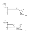
Fig. 2 is an explanatory diagram about charging operation of the charging circuit according to the first embodiment of the present invention,Fig. 2A shows a charging current and a charging voltage in a constant current charging operation and a constant voltage charging operation, andFig. 2B shows a completion time of the constant voltage charging operation and a charging amount of the charging operation; -
Fig. 3 is a diagram showing a charging current curve of the charge circuit according to the first embodiment of the present invention,Fig. 3A is related to a fresh second battery, andFig. 3B is related to a second battery which is repeatedly charged; -
Fig. 4 is an explanatory diagram showing a relation between a number of charging and a charge stop current value of the charge circuit according to the first embodiment of the present invention; -
Fig. 5 is a diagram showing a battery-charger assemblage according to the first embodiment of the present invention; -
Fig. 6 is a circuit diagram of a charge circuit according to a second embodiment of the present invention; -
Fig. 7 is a circuit diagram of a charge circuit according to a third embodiment of the present invention; and -
Fig. 8 is a diagram showing a charging current curve of a prior charge circuit,Fig. 8A is related to a fresh second battery, andFig. 8B is related to a second battery which is repeatedly charged. - The present invention is explained below with reference to embodiments illustrated in attached drawings.
-
Fig. 5 shows a battery-charger assemblage of the present embodiment. The battery-charger assemblage of the present embodiment is composed of at least one ("one" in the example ofFig. 5 )battery packs 4 each of which is provided with asecondary battery 41 therein, and at least one ("one" in the example ofFig. 5 )charger 2 for charging thesecondary battery 41 of thebattery pack 4. - The
charger 2 includes a chargermain body 200, an internal circuit (a first circuit) 1a, aplug 32 connected to theinternal circuit 1a, andterminals 7a (output terminals control terminals internal circuit 1a. Theinternal circuit 1a is housed in the chargermain body 200. Thebattery pack 4 includes a battery packmain body 400, an internal circuit (a second circuit) 1b, thesecond battery 41 connected to theinternal circuit 1b, andterminals 7b (input terminals control terminals internal circuit 1b. Thesecondary battery 41 includes at least one ("two" in the example ofFig. 5 )battery cells 50. Theinternal circuit 1 b and thesecondary battery 41 are housed in the battery packmain body 400. When connecting theplug 32 to anexternal power supply 8 such as a commercial power supply, and connecting theterminals 7a of thecharger 2 to theterminals 7b of thebattery pack 4, thereby thesecondary battery 41 of thebattery pack 4 can be charged. Thebattery pack 4 is mounted to an electric equipment such as an electric tool, and supplies an electric power to the electric equipment. Note that, outer shapes of thecharger 2 andbattery pack 4 are not limited to those shown inFig. 5 . - As shown in
Fig. 1 , acharge circuit 1 of the present embodiment is composed of the internal circuit (the first circuit) 1a provided at thecharger 2 and the internal circuit (the second circuit) 1b provided at thebattery pack 4. Theinternal circuit 1a of thecharger 2 and theinternal circuit 1b of thebattery pack 4 are connected through theterminals 7a (71 a, 72a, 73a, 74a) and theterminals 7b (71 b, 72b, 73b, 74b). - The
internal circuit 1a of thecharger 2 of the present embodiment includes: an output power supply section; a transformer for charging (a first transformer) 22, a controlpower supply block 24; a transformer for control (a second transformer) 25; aperipheral section 26; avoltage conversion section 27; aphoto coupler 28; an informingsection 29; acontrol section 3; and acurrent measurement section 30. The output power supply section includes arectification block 21 and acurrent output section 23. - The
rectification block 21 is connected to theplug 32. Therectification block 21 includes a full-wave rectifier or the like for rectifying an AC power supplied from theexternal power supply 8. The electric power rectified by therectification block 21 is applied to the transformer for charging 22. Thecharger 2 charges thesecondary battery 41 by supplying the output of the transformer for charging 22 to thesecondary battery 41 through theterminals 7a (71a, 72a), 7b (71 b, 72b). Note that, a rectification-smoothing circuit (including such as a rectification diode and a smoothing capacitor) is provided between the transformer for charging 22 and the output terminals (71 a, 72a). Thecurrent output section 23 is provided between therectification block 21 and the transformer for charging 22. Thecurrent output section 23 is configured to start/stop of the power feeding to the transformer for charging 22, and adjust the current flowing to the transformer for charging 22. Thecurrent output section 23 is preferably provided with a switching element. Thecontrol section 3 controls the switching frequency of the switching element of thecurrent output section 23. The current measurement section 30 (such as a resistance) is provided at the secondary side of the transformer for charging 22. Thecurrent measurement section 30 is adapted to measure the current (charging current) flowing from the output power supply section to thesecondary battery 41. - The control
power supply block 24 is connected to therectification block 21. Electric power adjusted by the controlpower supply block 24 is supplied to thecontrol section 3 through the transformer forcontrol 25. The secondary side of the transformer forcontrol 25 is connected with thecontrol section 3, aperipheral section 26 of a smoothing capacitor and the like, and the voltage conversion section 27 (such as a three-terminal regulator) for stabilizing an electric power. Thephoto coupler 28 is provided between thecontrol section 3 and thecurrent output section 23. Thecontrol section 3 controls the current output section 23 (the output power supply section) in an electrically-insulated manner through thephoto coupler 28. - The
internal circuit 1b of thebattery pack 4 includes amemory 42 and a constant voltage control element 43 (a voltage measurement section) for a charging operation. Thememory 42 stores an identification information and a lifetime information of thebattery pack 4 as a memory information. The identification information is used for thecontrol section 3 to identify an initial-value of a charge stop current value and a rated voltage of thebattery pack 4. The identification information may be an ID number. The lifetime information includes a number of charging which is defined as a number of times of performing a charging operation. That is, thememory 42 stores the identification information and the number of charging of thebattery pack 4. - The constant
voltage control element 43 is adapted to measure a voltage of the secondary battery 41 (and/or the battery cell 50) and to output the measured value (measured voltage value) to thecontrol section 3. The constantvoltage control element 43 is preferred to measure a voltage acrossterminals voltage control element 43 is sent to thecontrol section 3 of thecharger 2 through theterminals - The
control section 3 of the present embodiment has a constant current charging mode and a constant voltage charging mode. In the constant current charging mode, thecontrol section 3 controls the current output section 23 (the output power supply section) so as to keep the output current from thecurrent output section 23 constant (i.e. keep the measured value by thecurrent measurement section 30 constant) (constant current charging operation). In the constant voltage charging mode, thecontrol section 3 controls the current output section 23 (the output power supply section) to gradually decrease the output current from thecurrent output section 23 so that the voltage value of thesecondary battery 41, which is input from the constantvoltage control element 43, does not exceed a predetermined value. That is, in the constant voltage charging mode, thecontrol section 3 controls the current output section 23 (the output power supply section) so as to keep the voltage of thesecondary battery 41 constant (constant voltage charging operation). - When performing the charging operation (performing a control of charging), the
control section 3 reads the memory information (the identification information and the lifetime information) from thememory 42 of thebattery pack 4 mounted (attached) to thecharger 2. Then, thecontrol section 3 performs the charging operation using the memory information obtained from thememory 42. - In the charging operation, as shown in
Fig. 2A , thecontrol section 3 starts to charge by way of the constant current charging operation in which a charging current ("L1" inFig. 2A ) is kept at substantially constant and a charging voltage ("L2" inFig. 2A ) is gradually increased (refer to "AC1" inFig. 2A ). Upon the charging voltage reaches a predetermined set value (threshold voltage; refer to "B0" inFig. 2A ) during the constant current charging operation, thecontrol section 3 switches the charging operation into the constant voltage charging operation in which the charging voltage is kept at substantially constant and the charging current is gradually decreased (refer to "AC2" inFig. 2A ), and thecontrol section 3 keeps to charge by the constant voltage charging operation. As shown inFig. 2B , upon the charging current (which decreases gradually) reaches the charge stop current value (threshold current; refer to "A0" inFig. 2B ) during the constant voltage charging operation (i.e. upon the measured value by thecurrent measurement section 30 becomes small enough to reach the charge stop current value A0), thecontrol section 3 decides that the charge of thesecondary battery 41 has been completed, and finishes the charging operation. - In this instance, the
control section 3 of the present embodiment also has a function of a thresholdcurrent setting section 5 for determining the charge stop current value (threshold current) used for the charging operation. The thresholdcurrent setting section 5 changes the charge stop current value into a smaller value (which is smaller than the initial-value) according to the increased number of charging. - When performing the charging operation, the
control section 3 as the thresholdcurrent setting section 5 determines "a charge stop current value for the present charging operation" based on the number of charging (lifetime information) and the initial-value of the charge stop current value (identification information) obtained from thememory 42. For example, as shown inFig. 4 , the thresholdcurrent setting section 5 changes the charge stop current value into a smaller value at each time that the number of charging reaches a predetermined numbers (every 100th times in the example ofFig. 4 ). In this instance, for example, the thresholdcurrent setting section 5 has a plurality of data tables each of which, as shown inFig. 4 , includes a relationship between the number of charging and the charge stop current value. When abattery pack 4 is mounted to thecharger 2, the thresholdcurrent setting section 5 determines which data table to use based on the identification information (such as the initial-value of the charge stop current value). And then, the thresholdcurrent setting section 5 determines the charge stop current value based on the number of charging. Note that the thresholdcurrent setting section 5 may have a predetermined equation(s) which relates between the number of charging and the charge stop current value, instead of the data table(s). - The charge stop current value determined by the threshold
current setting section 5 is used in the constant voltage charging operation in the present charging operation. As shown inFig. 3 , thecontrol section 3 performs the charging operation using the charge stop current value according to the number of charging. In case of charging thesecondary battery 41 which has been repeatedly charged, thecontrol section 3 performs the charging operation using "the charge stop current value for the repeatedly charged battery (refer to "A2" inFig. 3B )" which is smaller than "the charge stop current value for the fresh battery (refer to "A1" inFig. 3 )". - In the following, the charge operation of the
charge circuit 1 of the present embodiment is explained in other words. - When the
terminals 7b of thebattery pack 4 are connected to theterminals 7a of thecharger 2, thecontrol section 3 obtains the memory information (the identification information and the number of charging) from thememory 42 of thebattery pack 4 through theterminals control section 3 as the thresholdcurrent setting section 5 determines the charge stop current value using the memory information obtained from thememory 42 and the data table (e.g. the data table as shown inFig. 4 ). Note that, the charge stop current value is set at smaller along with the increase of the number of charging. - At the time of starting the charging operation, the
control section 3 obtains a present voltage value of thesecondary battery 41 through the constantvoltage control element 43. - If the obtained voltage value is smaller than the predetermined value (smaller than the threshold voltage B0), the
control section 3 starts the charging operation by the constant current charging mode. In the constant current charging mode, thecontrol section 3 controls the current output section 23 (the output power supply section) so as to keep the charging current measured by thecurrent measurement section 30 at a predetermined value (at a target current value) with referring to the charging current measured by thecurrent measurement section 30 and the voltage value of thesecondary battery 41 input from the constant voltage control element 43 (constant current charging operation). Upon the voltage of thesecondary battery 41 reaches the predetermined value (the threshold voltage B0) during the constant current charging operation, thecontrol section 3 shifts into the constant voltage charging mode. In the constant voltage charging mode, thecontrol section 3 controls the current output section 23 (the output power supply section) so as to keep the voltage of thesecondary battery 41 at a predetermined value (at a target voltage value) with referring to the charging current measured by thecurrent measurement section 30 and the voltage value input from the constant voltage control element 43 (constant voltage charging operation). That is, in the constant voltage charging operation, thecontrol section 3 gradually decreases "the target current value" of the output current of thecurrent output section 23 so as to keep the voltage of thesecondary battery 41 at the target voltage value. Upon the target current value reaches the charge stop current value (A1, A2 or the like) determined by the thresholdcurrent setting section 5 during the constant voltage charging operation, thecontrol section 3 finishes the charging operation. - If the obtained voltage value is equal to the predetermined value (equal to the threshold voltage B0), the
control section 3 starts the charging operation by the constant voltage charging mode (constant voltage charging operation). Upon the target current value reaches the charge stop current value (A1, A2 or the like) determined by the thresholdcurrent setting section 5 during the constant voltage charging operation, thecontrol section 3 finishes the charging operation. - If the obtained voltage value is larger than the predetermined value (larger than the threshold voltage B0), the
control section 3 stops charging. - Note that, abovementioned "target voltage value" of the constant voltage charging operation is preferably equal to the "threshold voltage B0" of the constant current charging operation, but it may be different from each other.
- Note that, the
control section 3 adds the number of charging stored in thememory 42 by "one" at a predetermined timing during the charging operation. Thecontrol section 3 adds the number of charging when reading the memory information from thememory 42; or else, thecontrol section 3 adds the number of charging when shifting from the constant current charging operation into the constant voltage charging operation; or else, thecontrol section 3 adds the number of charging when finishing the constant voltage charging operation (i.e. finishing the charging operation); or else, thecontrol section 3 adds the number of charging when continuously charging for a predetermined time period. - As described above, in the present embodiment, the charge stop current value is set at smaller along with the increase of the number of charging. Therefore, as shown in
Fig. 3B , the present embodiment can charge thesecondary battery 41 even at a period in which the prior charge circuit (which has an invariable charge stop current value) does not charge thesecondary battery 41. As a result, the present embodiment can increase the charge amount of the repeatedly charged battery compared with the charge circuit which has an invariable charge stop current value. In other words, in the present embodiment, a part of the non-charging amount E12 (refer toFig. 8 ) is shifted into a "charging amount E1" as shown inFig. 3B (a part of non-charging amount E12 shifted into the charging amount E1 may be called as an "increased amount E3"). Therefore, a ratio of a non-charging amount E2 with respect to a chargeable amount E0 can be reduced compared with the prior charge circuit which has an invariable charge stop current value. As a result, the present embodiment can increase the charge amount of the repeatedly charged battery. That is, the present embodiment can performs the charging operation according to the number of charging. Therefore, the present embodiment can charge a sufficient amount of electric power to the repeatedly charged battery with compensating the reduction of charge amount due to the increase of the number of charging. Thus, the present embodiment improves the convenience of thebattery pack 4. - Note that, the
charger 2 includes the informingsection 29 for informing such as operation conditions. Thecontrol section 3 controls the informingsection 29. The informingsection 29 is adapted to inform such as: connection condition with theexternal power supply 8; beginning of the charging operation; completion of the charging operation; abnormal state of thecharger 2 orbattery pack 4; or the like. - The charge circuit of the second embodiment of the present invention is explained with reference to
Fig. 6 . Note that, similar configuration with the first embodiment is not described below. - In the present embodiment, as shown in
Fig. 6 , the thresholdcurrent setting section 5 is provided at the internal circuit (the second circuit) 1b of the battery back 4, and the charge stop current value (the threshold current) is changed (determined) at the battery back 4 side according to the number of charging. Then, the changed (determined) charge stop current value (threshold current) is sent to theinternal circuit 1a (control section 3) of thecharger 2 through theterminals - In detail, when the
battery pack 4 is mounted to thecharger 2, the thresholdcurrent setting section 5 in thebattery pack 4 reads the memory information from thememory 42, and changes the charge stop current value into a smaller value according to the number of charging based on the memory information. Then, the thresholdcurrent setting section 5 outputs the result value (the changed charge stop current value) to thecontrol section 3 through theterminals control section 3 uses this changed charge stop current value for the present charging operation. - Because the threshold
current setting section 5 is provided at the battery back 4, the charge stop current value can be changed into a smaller value according to the number of charging at the battery back 4 side. And then, thecontrol section 3 performs the charging operation using this changed charge stop current value. Therefore, the present embodiment can charge a sufficient amount of electric power to the repeatedly charged battery with compensating the reduction of charge amount due to the increase of the number of charging. Thus, the present embodiment improves the convenience of thebattery pack 4. - In addition, because the charge stop current value is changed at the battery back 4 side, the
charger 2 can performs the charging operation using the charge stop current value determined according to the number of charging, without having to change the charge stop current value at thecharger 2 side. Therefore, even when thecontrol section 3 does not have a function as the threshold current setting section 5 (that is, even when thecharger 2 does not include threshold current setting section 5), the present embodiment can charge a sufficient amount of electric power to the repeatedly charged battery with compensating the reduction of charge amount due to the increase of the number of charging. - The charge circuit of the third embodiment of the present invention is explained with reference to
Fig. 7 . Note that, similar configuration with the first embodiment is not described below. - In the present embodiment, the control section includes a charger
side control section 33 provided at the internal circuit (the first circuit) 1a of thecharger 2 and a battery side control section 45 provided at the internal circuit (the second circuit) 1b of the battery back 4. In addition, the battery side control section 45 has a function as the voltage measurement section for measuring the voltage of thesecondary battery 41 and a function as the thresholdcurrent setting section 5. In the present embodiment, as shown inFig. 7 , theinternal circuit 1b of the battery back 4 includes a battery sidecurrent measurement section 48 adapted to measure a current flowing from thecharger 2 to thesecondary battery 41. - In the present embodiment, the battery side control section 45 measures the voltage of the
secondary battery 41 as well as measures the charging current through the battery sidecurrent measurement section 48. Besides, when the battery back 4 is mounted to thecharger 2, the battery side control section 45 (the threshold current setting section 5) reads the memory information from thememory 42. And then, the battery side control section 45 (the threshold current setting section 5) determines the charge stop current value (i.e. changes the charge stop current value into a smaller value) according to the number of charging. - The battery side control section 45 of the present embodiment has a constant current charging mode and a constant voltage charging mode. In the constant current charging mode, the battery side control section 45 outputs (sends) a predetermined (constant) target current value to the charger
side control section 33. The chargerside control section 33 controls the current output section 23 (the output power supply section) so as to keep the measured current value by thecurrent measurement section 30 at the target current value. In the constant voltage charging mode, the battery side control section 45 gradually decreases the target current value output to the chargerside control section 33 so as to keep the voltage of thesecondary battery 41 at a predetermined value (at the target voltage value). The chargerside control section 33 controls the current output section 23 (the output power supply section) so that the measured current value by thecurrent measurement section 30 corresponds to the target current value. - According to the charging operation of the
charge circuit 1 of the present embodiment, the battery side control section 45 keeps the target current value output to the chargerside control section 33 constant throughout a time period from starting time of the charging operation to a time point at which the voltage of thesecondary battery 41 reaches the predetermined value (the threshold voltage B0). The chargerside control section 33 controls the current output section 23 (the output power supply section) so as to keep the measured current value by thecurrent measurement 30 at the target current value (constant current charging operation). Upon the voltage of thesecondary battery 41 reaches the threshold voltage B0, the battery side control section 45 shifts into the constant voltage charging mode. In this mode, the battery side control section 45 gradually decreases the target current value so as to keep the voltage of thesecondary battery 41 at the target voltage value (such as the threshold voltage B0). The chargerside control section 33 controls the current output section 23 (the output power supply section) so that the measured current value by thecurrent measurement 30 corresponds to the target current value (constant voltage charging operation). Upon the target current value reaches to the charge stop current value (i.e. the charging current measured by the battery sidecurrent measurement section 48 becomes small enough to reach the charge stop current value), the battery side control section 45 finishes the charging operation. - That is, in the present embodiment, the control section includes the charger
side control section 33 provided at thefirst circuit 1a and the battery side control section 45 provided at thesecond circuit 1b. Thesecond circuit 1b is provided with the battery sidecurrent measurement section 48 configured to measure the current flowing from the output power supply section to thesecondary battery 41. The battery side control section 45 is configured to send a target current value to the chargerside control section 33 with referring to the voltage of thesecondary battery 41 and the measured current value by the battery sidecurrent measurement section 48. In the constant current charging operation, the battery side control section 45 sends the target current value of a constant value to the chargerside control section 33, and the chargerside control section 33 controls the output power supply section so as to keep the measured current value by thecurrent measurement section 30 at the target current value. In the constant voltage charging operation, the battery side control section 45 is configured to gradually decrease the target current value sent to the chargerside control section 33 so as to keep the voltage of thesecondary battery 41 constant, and the chargerside control section 33 controls the output power supply section so that the measured value by thecurrent measurement section 30 corresponds to the target current value. - According to the present embodiment, the battery side control section 45 of the
battery pack 4 adjusts the target current value during each of the constant current charging operation and the constant voltage charging operation. That is, in the present embodiment, the chargerside control section 33 only needs to have a function of controlling the charging current based on the target current value sent from the battery side control section 45. - The present embodiment also can charge a sufficient amount of electric power to the repeatedly charged battery with compensating the reduction of charge amount due to the increase of the number of charging. Thus, the present embodiment improves the convenience of the
battery pack 4. - Note that, the present invention is not limited to the above described embodiments, and numerous modifications and variation can be made without departing from the true spirit and scope of the present invention, namely claims.
- For example, in the first embodiment, the
control section 3 and the thresholdcurrent setting section 5 can be separately provided at thecharger 2. In this configuration, the thresholdcurrent setting section 5 reads the memory information from thememory 42, determines the charge stop current value (changes the charge stop current value into a smaller value) according to the number of charging in the memory information, and outputs the changed charge stop current value into thecontrol section 3. - For example, the threshold
current setting section 5 may determine the charge stop current value so that a charging time of the present charging is correspondent to a charging time of the fresh battery. With this configuration, even when charging the repeatedly charged battery, the charging operation finishes at the same time with the charging of the fresh battery. - For example, the
memory 42 may store the data table(s) as shown inFig. 4 which includes a relationship between the number of charging and the charge stop current value. Then, the thresholdcurrent setting section 5 may read the data table and the number of charging from thememory 42, and determine the charge stop current value according to the number of charging. With this configuration, the thresholdcurrent setting section 5 can determine the charge stop current value (change the charge stop current value into a smaller value) without using the identification information (such as the initial-value of the charge stop current value) of thebattery pack 4. Therefore, the thresholdcurrent setting section 5 is not need to obtain the initial-value, or thememory 42 is not need to store the identification information (such as the initial-value). - For example, the
charger 2 is not limited to include the above output power supply section to which an electric power is supplied from theexternal power supply 8. That is, the output power supply section of thecharge 2 may be an internal power supply such as a power generator, and thereby thecharger 2 may charge thesecondary battery 41 using the electric power generated by the internal power supply.
Claims (6)
- A charge circuit (1) composed of a first circuit (1a) and a second circuit (1b), said second circuit (1b) being provided at a battery pack (4) in which a secondary battery (41) is comprised, said first circuit (1a) being provided at a charger (2) for charging said secondary battery (41) in said battery pack (4),
wherein said charge circuit (1) comprises:- an output power supply section (23) which is configured to output an electric power to said secondary battery (41);- a control section (3, 33, 45) which is configured to control said output power supply section (23) to perform a charging operation, wherein said control section (3, 33, 45) is configured to, in said charging operation, perform first a constant current charging operation, perform a constant voltage charging operation after finishing the constant current charging operation, and finish the charging operation when a charging current reaches a charge stop current value;- a memory (42) which stores a number of charging defined as the number of times of performing said charging operation, said memory (42) being provided at said second circuit (1b) in said battery pack (4); and- a threshold current setting section (5) configured to determine said charge stop current value, andwherein said threshold current setting section (5) is configured to decrease said charge stop current value along with the increase of said number of charging. - The charging circuit as set forth in claim 1, wherein said threshold current setting section (5) is provided at said first circuit (1a) in said charger (2).
- The charging circuit as set forth in claim 1, wherein said threshold current setting section (5) is provided at said second circuit (1b) of said battery pack (4).
- The charging circuit as set forth in any one claims of 1 to 3,
wherein said charge circuit (1) comprises: a current measurement section (30) for measuring a current flowing from said output power supply section (23) to said secondary battery (41); and a voltage measurement section (43, 45) for measuring a voltage of said secondary battery (41), and
wherein said control section (3, 33, 45) is configured to: control said output power supply section (23) so that the current measured by said current measurement section (30) corresponds to a predetermined target current value in said constant current charging operation; and control said output power supply section (23) so that the measured voltage of said voltage measurement section (43, 45) corresponds to a predetermined target voltage value in said constant voltage charging operation. - The charging circuit as set forth in claim 4, wherein said voltage measurement section (43, 45) is provided at said second circuit (1b) of said battery pack (4).
- A battery-charger assembly comprising said charging circuit as set forth in any one claims of 1 to 5, said battery-charger assembly including: at least one charger (2); and at least one battery pack (4),
wherein each of said at least one chargers (2) is provided with said first circuit (1a), and
wherein each of said at least one battery packs (4) is provided with said second circuit (1b).
Applications Claiming Priority (1)
| Application Number | Priority Date | Filing Date | Title |
|---|---|---|---|
| JP2011274477A JP2013126325A (en) | 2011-12-15 | 2011-12-15 | Charging circuit |
Publications (3)
| Publication Number | Publication Date |
|---|---|
| EP2605363A2 true EP2605363A2 (en) | 2013-06-19 |
| EP2605363A3 EP2605363A3 (en) | 2013-12-11 |
| EP2605363B1 EP2605363B1 (en) | 2021-02-03 |
Family
ID=47351493
Family Applications (1)
| Application Number | Title | Priority Date | Filing Date |
|---|---|---|---|
| EP12196844.0A Active EP2605363B1 (en) | 2011-12-15 | 2012-12-13 | Charge circuit, and battery-charger assemblage with the charge circuit |
Country Status (5)
| Country | Link |
|---|---|
| US (1) | US9142993B2 (en) |
| EP (1) | EP2605363B1 (en) |
| JP (1) | JP2013126325A (en) |
| KR (1) | KR101453618B1 (en) |
| CN (1) | CN103166283B (en) |
Cited By (3)
| Publication number | Priority date | Publication date | Assignee | Title |
|---|---|---|---|---|
| CN104753155A (en) * | 2014-11-14 | 2015-07-01 | 航天长峰朝阳电源有限公司 | Online type integrated switching type constant-current charging device |
| EP2919358A1 (en) * | 2014-03-11 | 2015-09-16 | Midastek Microelectronic Inc. | Smart power adaptor and method for controlling power supplay thereof |
| EP3627651A4 (en) * | 2018-05-31 | 2020-07-01 | Guangdong Oppo Mobile Telecommunications Corp., Ltd. | Charging method, and charging device |
Families Citing this family (15)
| Publication number | Priority date | Publication date | Assignee | Title |
|---|---|---|---|---|
| JP5077386B2 (en) * | 2010-04-28 | 2012-11-21 | ソニー株式会社 | Charge control method and battery pack |
| CN103701168B (en) * | 2013-12-12 | 2017-09-29 | 金蝶软件(中国)有限公司 | The charging management method and charging management system of lithium battery |
| KR102271730B1 (en) * | 2014-07-31 | 2021-07-02 | 삼성전자주식회사 | Charging control Method and Device |
| TWI523298B (en) * | 2015-01-16 | 2016-02-21 | 新普科技股份有限公司 | Method to estimate the charging time of lithium-ion batteries and charging monitor |
| JP5887641B1 (en) * | 2015-05-12 | 2016-03-16 | オービタルワークス株式会社 | Unmanned aerial vehicle |
| CN107681724A (en) * | 2015-10-28 | 2018-02-09 | 苏州乐米凡电气科技有限公司 | A kind of constant current voltage limiting formula lithium battery charger |
| CN105262330A (en) * | 2015-11-24 | 2016-01-20 | 国家电网公司 | Method and system for inhibiting ring current in battery charger of electric car |
| CN105375588A (en) * | 2015-12-21 | 2016-03-02 | 高铸成 | Micro conducting device and self-charging device with micro conducting device |
| JP6202407B2 (en) * | 2016-01-22 | 2017-09-27 | オービタルワークス株式会社 | Unmanned aerial vehicle |
| CN105826976A (en) * | 2016-03-30 | 2016-08-03 | 维沃移动通信有限公司 | Mobile terminal charging method and mobile terminal |
| CN107336611B (en) * | 2016-11-18 | 2019-06-04 | 安徽江淮汽车集团股份有限公司 | A kind of car battery sensor matching process and system |
| WO2019232065A1 (en) | 2018-05-30 | 2019-12-05 | Milwaukee Electric Tool Corporation | Fast-charging battery pack |
| TWI672844B (en) | 2018-12-19 | 2019-09-21 | 財團法人工業技術研究院 | The method and device for charging alluminum battery |
| JP2021164302A (en) * | 2020-03-31 | 2021-10-11 | パナソニックIpマネジメント株式会社 | Charging system, charging method, and program |
| CN112345944B (en) * | 2020-10-23 | 2023-06-16 | Oppo广东移动通信有限公司 | Battery abnormality detection method, apparatus, electronic device, and computer-readable storage medium |
Citations (1)
| Publication number | Priority date | Publication date | Assignee | Title |
|---|---|---|---|---|
| JP2007143279A (en) | 2005-11-17 | 2007-06-07 | Matsushita Electric Works Ltd | Charging method, charging circuit and charger |
Family Cites Families (16)
| Publication number | Priority date | Publication date | Assignee | Title |
|---|---|---|---|---|
| JPH04197043A (en) | 1990-11-27 | 1992-07-16 | Matsushita Electric Ind Co Ltd | Charger |
| JP2929921B2 (en) | 1993-12-21 | 1999-08-03 | 三菱電機株式会社 | Electronic device, battery management device, and battery management method |
| JP3727508B2 (en) | 2000-04-13 | 2005-12-14 | 株式会社マキタ | Charging device and battery charging characteristics update method |
| JP3767438B2 (en) * | 2001-09-07 | 2006-04-19 | 日産自動車株式会社 | Charging apparatus and charging method |
| JP3901140B2 (en) | 2003-08-26 | 2007-04-04 | 松下電工株式会社 | Charger |
| US7202635B2 (en) * | 2004-03-10 | 2007-04-10 | Motorola, Inc. | Method and system for charging a battery to a point less than initial maximum capacity |
| JP2007195367A (en) * | 2006-01-20 | 2007-08-02 | Casio Hitachi Mobile Communications Co Ltd | Charging system and charging program |
| JP5268330B2 (en) * | 2006-12-04 | 2013-08-21 | パナソニック株式会社 | Charging system, charging device, and battery pack |
| US8013577B2 (en) * | 2006-12-04 | 2011-09-06 | Panasonic Corporation | Charging system, charging apparatus and battery pack |
| JP2008252960A (en) * | 2007-03-29 | 2008-10-16 | Matsushita Electric Ind Co Ltd | Charging system, charging pack and its charging method |
| JP2008295172A (en) * | 2007-05-23 | 2008-12-04 | Canon Inc | Battery pack, charger and electronic apparatus |
| JP4943296B2 (en) * | 2007-10-30 | 2012-05-30 | ソニー株式会社 | Battery pack, secondary battery charging method, and charging device |
| JP2010068571A (en) * | 2008-09-09 | 2010-03-25 | Hitachi Koki Co Ltd | Charging apparatus |
| JP5400333B2 (en) * | 2008-09-24 | 2014-01-29 | パナソニック株式会社 | Charger |
| CN102472797A (en) * | 2009-07-10 | 2012-05-23 | 松下电器产业株式会社 | Circuit for counting number of cycles, battery pack, and battery system |
| JP2011205839A (en) * | 2010-03-26 | 2011-10-13 | Hitachi Koki Co Ltd | Charger and battery pack |
-
2011
- 2011-12-15 JP JP2011274477A patent/JP2013126325A/en active Pending
-
2012
- 2012-12-05 US US13/705,540 patent/US9142993B2/en active Active
- 2012-12-13 KR KR1020120145148A patent/KR101453618B1/en active IP Right Grant
- 2012-12-13 EP EP12196844.0A patent/EP2605363B1/en active Active
- 2012-12-14 CN CN201210545324.4A patent/CN103166283B/en active Active
Patent Citations (1)
| Publication number | Priority date | Publication date | Assignee | Title |
|---|---|---|---|---|
| JP2007143279A (en) | 2005-11-17 | 2007-06-07 | Matsushita Electric Works Ltd | Charging method, charging circuit and charger |
Cited By (6)
| Publication number | Priority date | Publication date | Assignee | Title |
|---|---|---|---|---|
| EP2919358A1 (en) * | 2014-03-11 | 2015-09-16 | Midastek Microelectronic Inc. | Smart power adaptor and method for controlling power supplay thereof |
| US9413262B2 (en) | 2014-03-11 | 2016-08-09 | Midastek Microelectronic Inc. | Smart power adaptor and method for controlling power supplay thereof |
| CN104753155A (en) * | 2014-11-14 | 2015-07-01 | 航天长峰朝阳电源有限公司 | Online type integrated switching type constant-current charging device |
| CN104753155B (en) * | 2014-11-14 | 2017-11-03 | 航天长峰朝阳电源有限公司 | Online integrated switch mode constant current charger |
| EP3627651A4 (en) * | 2018-05-31 | 2020-07-01 | Guangdong Oppo Mobile Telecommunications Corp., Ltd. | Charging method, and charging device |
| US11539229B2 (en) | 2018-05-31 | 2022-12-27 | Guangdong Oppo Mobile Telecommunications Corp., Ltd. | Multi-stage constant current charging method and charging apparatus |
Also Published As
| Publication number | Publication date |
|---|---|
| CN103166283B (en) | 2016-07-06 |
| US9142993B2 (en) | 2015-09-22 |
| EP2605363B1 (en) | 2021-02-03 |
| US20130154578A1 (en) | 2013-06-20 |
| JP2013126325A (en) | 2013-06-24 |
| CN103166283A (en) | 2013-06-19 |
| KR101453618B1 (en) | 2014-10-22 |
| EP2605363A3 (en) | 2013-12-11 |
| KR20130069442A (en) | 2013-06-26 |
Similar Documents
| Publication | Publication Date | Title |
|---|---|---|
| EP2605363B1 (en) | Charge circuit, and battery-charger assemblage with the charge circuit | |
| CN101267124B (en) | Battery pack | |
| CN1071057C (en) | Battery charging apparatus | |
| US7567062B2 (en) | Charging circuit | |
| EP2869392A2 (en) | Charging method of battery and battery charging system | |
| US7619389B2 (en) | Charge control device for a secondary battery | |
| CN101299544A (en) | Battery pack, battery charger and charging method | |
| US9780592B2 (en) | Battery pack for selectively setting a high capacity mode having a high charge capacity until a full charge of a secondary battery | |
| JP5410248B2 (en) | Charging system that guarantees the lifetime of secondary batteries | |
| KR101863454B1 (en) | Inter-Cell Balancing Method and System for Battery Charging using the Combined Method of Serial Whole Charging and Selective Supplementary Charging | |
| EP2903127A1 (en) | Charging device | |
| WO2013042293A1 (en) | Rechargeable electrical device | |
| JP2007267498A (en) | Charger, charging system and electric apparatus | |
| JP4251158B2 (en) | Charger and electric tool set using the same | |
| CN104769806A (en) | Method and device for charging batteries | |
| JP5887531B2 (en) | Charger | |
| CN101647177A (en) | Fast battery charger device and method | |
| JP5165405B2 (en) | Charge control circuit, battery pack, and charging system | |
| EP2571137B1 (en) | Circuit for a small electric appliance with an accumulator and method for measuring a charging current | |
| JP2017053657A (en) | Battery testing device | |
| JP2021083137A (en) | Charge control device | |
| JP2007267499A (en) | Charger, charging system and electric apparatus | |
| CN110521052B (en) | Storage battery device | |
| US10673254B2 (en) | Simple battery and charger system | |
| JP2017099213A (en) | Charger and charging method |
Legal Events
| Date | Code | Title | Description |
|---|---|---|---|
| PUAI | Public reference made under article 153(3) epc to a published international application that has entered the european phase |
Free format text: ORIGINAL CODE: 0009012 |
|
| 17P | Request for examination filed |
Effective date: 20121213 |
|
| AK | Designated contracting states |
Kind code of ref document: A2 Designated state(s): AL AT BE BG CH CY CZ DE DK EE ES FI FR GB GR HR HU IE IS IT LI LT LU LV MC MK MT NL NO PL PT RO RS SE SI SK SM TR |
|
| AX | Request for extension of the european patent |
Extension state: BA ME |
|
| PUAL | Search report despatched |
Free format text: ORIGINAL CODE: 0009013 |
|
| AK | Designated contracting states |
Kind code of ref document: A3 Designated state(s): AL AT BE BG CH CY CZ DE DK EE ES FI FR GB GR HR HU IE IS IT LI LT LU LV MC MK MT NL NO PL PT RO RS SE SI SK SM TR |
|
| AX | Request for extension of the european patent |
Extension state: BA ME |
|
| RIC1 | Information provided on ipc code assigned before grant |
Ipc: H02J 7/04 20060101AFI20131105BHEP Ipc: H02J 7/00 20060101ALI20131105BHEP |
|
| RAP1 | Party data changed (applicant data changed or rights of an application transferred) |
Owner name: PANASONIC INTELLECTUAL PROPERTY MANAGEMENT CO., LT |
|
| STAA | Information on the status of an ep patent application or granted ep patent |
Free format text: STATUS: EXAMINATION IS IN PROGRESS |
|
| 17Q | First examination report despatched |
Effective date: 20200330 |
|
| GRAP | Despatch of communication of intention to grant a patent |
Free format text: ORIGINAL CODE: EPIDOSNIGR1 |
|
| STAA | Information on the status of an ep patent application or granted ep patent |
Free format text: STATUS: GRANT OF PATENT IS INTENDED |
|
| RIN1 | Information on inventor provided before grant (corrected) |
Inventor name: IKEDA, MASAKI Inventor name: KAWAI, AKIRA |
|
| INTG | Intention to grant announced |
Effective date: 20200820 |
|
| GRAS | Grant fee paid |
Free format text: ORIGINAL CODE: EPIDOSNIGR3 |
|
| GRAA | (expected) grant |
Free format text: ORIGINAL CODE: 0009210 |
|
| STAA | Information on the status of an ep patent application or granted ep patent |
Free format text: STATUS: THE PATENT HAS BEEN GRANTED |
|
| AK | Designated contracting states |
Kind code of ref document: B1 Designated state(s): AL AT BE BG CH CY CZ DE DK EE ES FI FR GB GR HR HU IE IS IT LI LT LU LV MC MK MT NL NO PL PT RO RS SE SI SK SM TR |
|
| REG | Reference to a national code |
Ref country code: GB Ref legal event code: FG4D |
|
| REG | Reference to a national code |
Ref country code: AT Ref legal event code: REF Ref document number: 1359914 Country of ref document: AT Kind code of ref document: T Effective date: 20210215 Ref country code: CH Ref legal event code: EP |
|
| REG | Reference to a national code |
Ref country code: DE Ref legal event code: R096 Ref document number: 602012074324 Country of ref document: DE |
|
| REG | Reference to a national code |
Ref country code: IE Ref legal event code: FG4D |
|
| REG | Reference to a national code |
Ref country code: NL Ref legal event code: MP Effective date: 20210203 |
|
| REG | Reference to a national code |
Ref country code: LT Ref legal event code: MG9D |
|
| REG | Reference to a national code |
Ref country code: AT Ref legal event code: MK05 Ref document number: 1359914 Country of ref document: AT Kind code of ref document: T Effective date: 20210203 |
|
| PG25 | Lapsed in a contracting state [announced via postgrant information from national office to epo] |
Ref country code: BG Free format text: LAPSE BECAUSE OF FAILURE TO SUBMIT A TRANSLATION OF THE DESCRIPTION OR TO PAY THE FEE WITHIN THE PRESCRIBED TIME-LIMIT Effective date: 20210503 Ref country code: NO Free format text: LAPSE BECAUSE OF FAILURE TO SUBMIT A TRANSLATION OF THE DESCRIPTION OR TO PAY THE FEE WITHIN THE PRESCRIBED TIME-LIMIT Effective date: 20210503 Ref country code: LT Free format text: LAPSE BECAUSE OF FAILURE TO SUBMIT A TRANSLATION OF THE DESCRIPTION OR TO PAY THE FEE WITHIN THE PRESCRIBED TIME-LIMIT Effective date: 20210203 Ref country code: PT Free format text: LAPSE BECAUSE OF FAILURE TO SUBMIT A TRANSLATION OF THE DESCRIPTION OR TO PAY THE FEE WITHIN THE PRESCRIBED TIME-LIMIT Effective date: 20210604 Ref country code: HR Free format text: LAPSE BECAUSE OF FAILURE TO SUBMIT A TRANSLATION OF THE DESCRIPTION OR TO PAY THE FEE WITHIN THE PRESCRIBED TIME-LIMIT Effective date: 20210203 Ref country code: FI Free format text: LAPSE BECAUSE OF FAILURE TO SUBMIT A TRANSLATION OF THE DESCRIPTION OR TO PAY THE FEE WITHIN THE PRESCRIBED TIME-LIMIT Effective date: 20210203 Ref country code: GR Free format text: LAPSE BECAUSE OF FAILURE TO SUBMIT A TRANSLATION OF THE DESCRIPTION OR TO PAY THE FEE WITHIN THE PRESCRIBED TIME-LIMIT Effective date: 20210504 |
|
| PG25 | Lapsed in a contracting state [announced via postgrant information from national office to epo] |
Ref country code: SE Free format text: LAPSE BECAUSE OF FAILURE TO SUBMIT A TRANSLATION OF THE DESCRIPTION OR TO PAY THE FEE WITHIN THE PRESCRIBED TIME-LIMIT Effective date: 20210203 Ref country code: AT Free format text: LAPSE BECAUSE OF FAILURE TO SUBMIT A TRANSLATION OF THE DESCRIPTION OR TO PAY THE FEE WITHIN THE PRESCRIBED TIME-LIMIT Effective date: 20210203 Ref country code: RS Free format text: LAPSE BECAUSE OF FAILURE TO SUBMIT A TRANSLATION OF THE DESCRIPTION OR TO PAY THE FEE WITHIN THE PRESCRIBED TIME-LIMIT Effective date: 20210203 Ref country code: NL Free format text: LAPSE BECAUSE OF FAILURE TO SUBMIT A TRANSLATION OF THE DESCRIPTION OR TO PAY THE FEE WITHIN THE PRESCRIBED TIME-LIMIT Effective date: 20210203 Ref country code: LV Free format text: LAPSE BECAUSE OF FAILURE TO SUBMIT A TRANSLATION OF THE DESCRIPTION OR TO PAY THE FEE WITHIN THE PRESCRIBED TIME-LIMIT Effective date: 20210203 Ref country code: PL Free format text: LAPSE BECAUSE OF FAILURE TO SUBMIT A TRANSLATION OF THE DESCRIPTION OR TO PAY THE FEE WITHIN THE PRESCRIBED TIME-LIMIT Effective date: 20210203 |
|
| PG25 | Lapsed in a contracting state [announced via postgrant information from national office to epo] |
Ref country code: IS Free format text: LAPSE BECAUSE OF FAILURE TO SUBMIT A TRANSLATION OF THE DESCRIPTION OR TO PAY THE FEE WITHIN THE PRESCRIBED TIME-LIMIT Effective date: 20210603 |
|
| PG25 | Lapsed in a contracting state [announced via postgrant information from national office to epo] |
Ref country code: SM Free format text: LAPSE BECAUSE OF FAILURE TO SUBMIT A TRANSLATION OF THE DESCRIPTION OR TO PAY THE FEE WITHIN THE PRESCRIBED TIME-LIMIT Effective date: 20210203 Ref country code: CZ Free format text: LAPSE BECAUSE OF FAILURE TO SUBMIT A TRANSLATION OF THE DESCRIPTION OR TO PAY THE FEE WITHIN THE PRESCRIBED TIME-LIMIT Effective date: 20210203 Ref country code: EE Free format text: LAPSE BECAUSE OF FAILURE TO SUBMIT A TRANSLATION OF THE DESCRIPTION OR TO PAY THE FEE WITHIN THE PRESCRIBED TIME-LIMIT Effective date: 20210203 |
|
| REG | Reference to a national code |
Ref country code: DE Ref legal event code: R097 Ref document number: 602012074324 Country of ref document: DE |
|
| PG25 | Lapsed in a contracting state [announced via postgrant information from national office to epo] |
Ref country code: SK Free format text: LAPSE BECAUSE OF FAILURE TO SUBMIT A TRANSLATION OF THE DESCRIPTION OR TO PAY THE FEE WITHIN THE PRESCRIBED TIME-LIMIT Effective date: 20210203 Ref country code: DK Free format text: LAPSE BECAUSE OF FAILURE TO SUBMIT A TRANSLATION OF THE DESCRIPTION OR TO PAY THE FEE WITHIN THE PRESCRIBED TIME-LIMIT Effective date: 20210203 Ref country code: ES Free format text: LAPSE BECAUSE OF FAILURE TO SUBMIT A TRANSLATION OF THE DESCRIPTION OR TO PAY THE FEE WITHIN THE PRESCRIBED TIME-LIMIT Effective date: 20210203 Ref country code: RO Free format text: LAPSE BECAUSE OF FAILURE TO SUBMIT A TRANSLATION OF THE DESCRIPTION OR TO PAY THE FEE WITHIN THE PRESCRIBED TIME-LIMIT Effective date: 20210203 |
|
| PLBE | No opposition filed within time limit |
Free format text: ORIGINAL CODE: 0009261 |
|
| STAA | Information on the status of an ep patent application or granted ep patent |
Free format text: STATUS: NO OPPOSITION FILED WITHIN TIME LIMIT |
|
| 26N | No opposition filed |
Effective date: 20211104 |
|
| PG25 | Lapsed in a contracting state [announced via postgrant information from national office to epo] |
Ref country code: AL Free format text: LAPSE BECAUSE OF FAILURE TO SUBMIT A TRANSLATION OF THE DESCRIPTION OR TO PAY THE FEE WITHIN THE PRESCRIBED TIME-LIMIT Effective date: 20210203 |
|
| PG25 | Lapsed in a contracting state [announced via postgrant information from national office to epo] |
Ref country code: SI Free format text: LAPSE BECAUSE OF FAILURE TO SUBMIT A TRANSLATION OF THE DESCRIPTION OR TO PAY THE FEE WITHIN THE PRESCRIBED TIME-LIMIT Effective date: 20210203 |
|
| PG25 | Lapsed in a contracting state [announced via postgrant information from national office to epo] |
Ref country code: IT Free format text: LAPSE BECAUSE OF FAILURE TO SUBMIT A TRANSLATION OF THE DESCRIPTION OR TO PAY THE FEE WITHIN THE PRESCRIBED TIME-LIMIT Effective date: 20210203 |
|
| PG25 | Lapsed in a contracting state [announced via postgrant information from national office to epo] |
Ref country code: IS Free format text: LAPSE BECAUSE OF FAILURE TO SUBMIT A TRANSLATION OF THE DESCRIPTION OR TO PAY THE FEE WITHIN THE PRESCRIBED TIME-LIMIT Effective date: 20210603 |
|
| PG25 | Lapsed in a contracting state [announced via postgrant information from national office to epo] |
Ref country code: MC Free format text: LAPSE BECAUSE OF FAILURE TO SUBMIT A TRANSLATION OF THE DESCRIPTION OR TO PAY THE FEE WITHIN THE PRESCRIBED TIME-LIMIT Effective date: 20210203 |
|
| REG | Reference to a national code |
Ref country code: CH Ref legal event code: PL |
|
| GBPC | Gb: european patent ceased through non-payment of renewal fee |
Effective date: 20211213 |
|
| REG | Reference to a national code |
Ref country code: BE Ref legal event code: MM Effective date: 20211231 |
|
| PG25 | Lapsed in a contracting state [announced via postgrant information from national office to epo] |
Ref country code: LU Free format text: LAPSE BECAUSE OF NON-PAYMENT OF DUE FEES Effective date: 20211213 Ref country code: IE Free format text: LAPSE BECAUSE OF NON-PAYMENT OF DUE FEES Effective date: 20211213 Ref country code: GB Free format text: LAPSE BECAUSE OF NON-PAYMENT OF DUE FEES Effective date: 20211213 |
|
| PG25 | Lapsed in a contracting state [announced via postgrant information from national office to epo] |
Ref country code: FR Free format text: LAPSE BECAUSE OF NON-PAYMENT OF DUE FEES Effective date: 20211231 Ref country code: BE Free format text: LAPSE BECAUSE OF NON-PAYMENT OF DUE FEES Effective date: 20211231 |
|
| PG25 | Lapsed in a contracting state [announced via postgrant information from national office to epo] |
Ref country code: LI Free format text: LAPSE BECAUSE OF NON-PAYMENT OF DUE FEES Effective date: 20211231 Ref country code: CH Free format text: LAPSE BECAUSE OF NON-PAYMENT OF DUE FEES Effective date: 20211231 |
|
| PG25 | Lapsed in a contracting state [announced via postgrant information from national office to epo] |
Ref country code: HU Free format text: LAPSE BECAUSE OF FAILURE TO SUBMIT A TRANSLATION OF THE DESCRIPTION OR TO PAY THE FEE WITHIN THE PRESCRIBED TIME-LIMIT; INVALID AB INITIO Effective date: 20121213 Ref country code: CY Free format text: LAPSE BECAUSE OF FAILURE TO SUBMIT A TRANSLATION OF THE DESCRIPTION OR TO PAY THE FEE WITHIN THE PRESCRIBED TIME-LIMIT Effective date: 20210203 |
|
| PGFP | Annual fee paid to national office [announced via postgrant information from national office to epo] |
Ref country code: DE Payment date: 20231214 Year of fee payment: 12 |