CN101299544A - Battery pack, battery charger and charging method - Google Patents
Battery pack, battery charger and charging method Download PDFInfo
- Publication number
- CN101299544A CN101299544A CNA2008100852858A CN200810085285A CN101299544A CN 101299544 A CN101299544 A CN 101299544A CN A2008100852858 A CNA2008100852858 A CN A2008100852858A CN 200810085285 A CN200810085285 A CN 200810085285A CN 101299544 A CN101299544 A CN 101299544A
- Authority
- CN
- China
- Prior art keywords
- battery pack
- charge
- battery
- voltage
- timeout period
- Prior art date
- Legal status (The legal status is an assumption and is not a legal conclusion. Google has not performed a legal analysis and makes no representation as to the accuracy of the status listed.)
- Pending
Links
Images


Classifications
-
- H—ELECTRICITY
- H01—ELECTRIC ELEMENTS
- H01M—PROCESSES OR MEANS, e.g. BATTERIES, FOR THE DIRECT CONVERSION OF CHEMICAL ENERGY INTO ELECTRICAL ENERGY
- H01M10/00—Secondary cells; Manufacture thereof
- H01M10/42—Methods or arrangements for servicing or maintenance of secondary cells or secondary half-cells
- H01M10/44—Methods for charging or discharging
-
- H—ELECTRICITY
- H02—GENERATION; CONVERSION OR DISTRIBUTION OF ELECTRIC POWER
- H02J—CIRCUIT ARRANGEMENTS OR SYSTEMS FOR SUPPLYING OR DISTRIBUTING ELECTRIC POWER; SYSTEMS FOR STORING ELECTRIC ENERGY
- H02J7/00—Circuit arrangements for charging or depolarising batteries or for supplying loads from batteries
- H02J7/007—Regulation of charging or discharging current or voltage
- H02J7/0071—Regulation of charging or discharging current or voltage with a programmable schedule
-
- Y—GENERAL TAGGING OF NEW TECHNOLOGICAL DEVELOPMENTS; GENERAL TAGGING OF CROSS-SECTIONAL TECHNOLOGIES SPANNING OVER SEVERAL SECTIONS OF THE IPC; TECHNICAL SUBJECTS COVERED BY FORMER USPC CROSS-REFERENCE ART COLLECTIONS [XRACs] AND DIGESTS
- Y02—TECHNOLOGIES OR APPLICATIONS FOR MITIGATION OR ADAPTATION AGAINST CLIMATE CHANGE
- Y02E—REDUCTION OF GREENHOUSE GAS [GHG] EMISSIONS, RELATED TO ENERGY GENERATION, TRANSMISSION OR DISTRIBUTION
- Y02E60/00—Enabling technologies; Technologies with a potential or indirect contribution to GHG emissions mitigation
- Y02E60/10—Energy storage using batteries
Landscapes
- Engineering & Computer Science (AREA)
- Power Engineering (AREA)
- Manufacturing & Machinery (AREA)
- Chemical & Material Sciences (AREA)
- Chemical Kinetics & Catalysis (AREA)
- Electrochemistry (AREA)
- General Chemical & Material Sciences (AREA)
- Charge And Discharge Circuits For Batteries Or The Like (AREA)
- Secondary Cells (AREA)
Abstract
A battery pack, a battery charger, a method for charging a battery pack are provided. The battery pack includes a secondary battery, a switch element for controlling charging and discharging the secondary battery, a controller for controlling the switch element, and a communication unit for performing with a battery charger. During charging, an initial charging is switched to a quick charging when a voltage of the secondary battery reaches a predetermined voltage, and the battery charger judges the battery pack as abnormal when the voltage does not reach the predetermined voltage within a timeout period after the initial charging is started. At least one of the timeout period and the predetermined is stored. At least one of the timeout period and the predetermined voltage to be read out is transmitted through the communication unit to the battery charger.
Description
CROSS-REFERENCE TO RELATED APPLICATIONS
The application requires to be submitted on March 9th, 2007 senior interest of Japanese patent application 2007-61060 number of Japan Patent office, and the full content of this application is incorporated in this by reference.
Technical field
The present invention relates to have rechargeable battery battery pack, the battery charger and being used to of (secondary battery) charging method of this battery pack of charging.
Background technology
Recently, portable electricity consuming products equipment such as notebook type PC (personal computer), cellular phone and PDA (personal digital assistant) is widely current, as its power supply, use the battery pack of Li-Ion rechargeable battery also to be extensive use of with high voltage, high-energy-density and light weight advantage.Manufacturing has these battery pack of different capabilities, different charge rates with purpose corresponding to the equipment that will use.In this specification, term " battery pack " refers to some such things, therein, rechargeable battery, be used for controlling this rechargeable battery charge or discharge circuit part and be used to carry out with the communication unit of communicating by letter of battery charger and be integrated into single device.
By convention, be used for the respective battery charger of rechargeable battery set according to making such as the capacity of battery pack and the characteristic the charge rate.If when making new battery charger, all make the electrical equipment charger that adapts to described characteristic, will increase manufacturing cost.In addition, be connected to the battery charger that does not adapt to this battery pack, then may show the potential hazard situation such as heating or burning if having the battery pack of identical in fact profile and different qualities.
Therefore, used recently and can carry out charging to mate the battery charger of polytype battery pack.Necessity of making new charger has been eliminated in the use of such battery charger, and single battery charger can be to having for example batteries charging of different battery capacities.The charger of polytype battery pack of can charging is designed to usually to low-capacity batteries group in the respective battery group and low charge rate batteries charging.Therefore, for example, the charging current that flows to battery pack from charger between charge period is designed to low coupling low-capacity batteries group.
As the fast charge mode of the rechargeable battery such as Li-Ion rechargeable battery, use CCCV (constant current constant voltage) charge mode as the combination of constant current charge and constant voltage charge.Under the CCCV charge mode, as shown in Figure 9, charge with constant current, till the cell voltage of battery pack reaches predetermined voltage, and after reaching predetermined voltage, charge with constant voltage.Having converged in charging current is the moment (point) the termination charging of zero ampere basically.
For example, in cell voltage V is 4.1V or following scope, carry out constant current charge with A=500mA.When the cell voltage (internal e.m.f.) of rechargeable battery increases because of charging and cell voltage V when becoming greater than 4.1V, the operation of charge power supply part is switched to constant voltage control, and charging current A reduces gradually.Cell voltage V increases towards the output voltage (4.2V) of power unit.Subsequently, when charging current basically near zero the time, finish charging.As detecting the method that charging is finished, know electric current detecting method and Δ V detection method.
Usually, when the high-capacity battery group is carried out quick charge, can with than the high charging current of the charging current of low-capacity batteries group to batteries charging.Yet, when the conventional batteries charger that uses polytype battery pack of can charging charge to the high-capacity battery group, with default to charger, be used for the low charging current that the low-capacity batteries group is charged is charged.Therefore, if to high-capacity battery group charging, then the constant current charge period elongated, thereby will spend a lot of times to charge.
That is to say that when using the conventional batteries charger to high-capacity battery group or high charge rate batteries charging, its characteristic may be not exclusively satisfied in charging, thereby causes the problem of spending a lot of charging intervals.
In order to address the above problem, for example, as disclosing in Japanese Unexamined Patent Application as described in 9-285026 number (hereinafter referred to as " patent documentation 1 "), having proposed can be by the battery charger of the respective battery group of correctly charging according to the characteristic changing charging current of battery pack.Patent documentation 1 described battery charger for example obtains information about maximum charging current and maximum charging voltage from the respective battery group.This battery charger is designed to based on that obtained, next in constant current period change charging current about the information of maximum charging current and maximum charging voltage.
Specifically, as shown in figure 11, be arranged in the constant current period of high-capacity battery group, pass through electric current with the current value of the charging current that is higher than the low-capacity batteries group.This makes it possible to correctly the high-capacity battery group be charged, thereby than reducing the charging interval with the charging of conventional batteries charger.
Therefore, the battery pack with different qualities can correctly be charged, and can reduce the charging interval by the information change charging current based on the maximum charging current that obtains from the respective battery group.
Summary of the invention
Simultaneously, when when normal charging current is lower than the condition of predetermined voltage by the cell voltage in battery pack under, carrying out quick charge and flowing through battery pack, may cause the unusual incident (abnormalevent) such as heating.Owing to this reason, the charging current that for example 100mA to 200mA is so little before quick charge usually flows through battery pack, so that initial charge continues, till the cell voltage of battery pack reaches predetermined voltage.
The device that charges the battery is preset predetermined voltage (following be called in some cases " switched voltage (switching voltage) "), as the voltage threshold that is used for charge mode is switched to from initial charge quick charge.When the cell voltage of battery pack during initial charge reaches switched voltage, the beginning quick charge.Battery charger is equipped with the timer that timeout period is set.That is to say, when the cell voltage of battery pack does not reach switched voltage in scheduled time slot,, battery pack is judged as abnormality and stops charging based on timeout period.
Consider to use the situation of conventional batteries charging high-capacity battery group now.Battery pack is set to for example timeout period and switched voltage, to mate conventional low-capacity batteries group.
As shown in figure 12, the high-capacity battery group is compared the voltage that has than low velocity and is risen with the low-capacity batteries group, therefore it spends a lot of times, and till the cell voltage of battery pack reaches switched voltage, and it may surpass the timeout period of the timer that is set to battery charger.Therefore, in this case, even the high-capacity battery group is in normal condition, battery pack also may be judged as the battery pack abnormality, and charging also may be stopped.
Also exist to have high performance battery pack, by the material that uses in Change Example such as the electrode, the voltage (as shown in figure 13) that it can discharge and reach lower than conventional batteries group.High performance battery can be discharged and be reached the voltage lower than conventional batteries group, thereby makes that drawing more discharge capacities becomes possibility.
The same with above-mentioned high-capacity battery group, rise by improving the voltage that high-capacity battery group that performance obtains has than low-capacity batteries group lower speed.Therefore, when being configured to by its switched voltage mate the battery charger execution charging of conventional batteries group, even battery pack is in normal condition, the charging processor controls also may be judged as abnormality, and stops charging because the measured time surpasses timeout period.
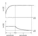
High performance battery also can be carried out quick charge from the voltage lower than conventional batteries group.When high performance battery when being provided with switched voltage that permission switches to quick charge from initial charge conventional batteries charger and charging with coupling conventional batteries group, the cell voltage of battery pack may need the longer charging interval, even being initial charge, reason after the cell voltage of battery pack is able to switch to the voltage of quick charge, still continues, as shown in Figure 14.
Therefore, in the conventional batteries charger, timeout period and the switched voltage relevant with the switching from the initial charge to the quick charge are arranged to mate the low-capacity batteries group, thereby feasible correct charging high-capacity battery group and high charge rate battery pack are very difficult.
The method of such battery pack, battery charger and this battery pack of charging preferably is provided, and it is designed to correctly polytype battery pack be charged.
According to the embodiment of the present invention, provide battery pack, it comprises: rechargeable battery; Switch element is used to control the charging and the discharge of this rechargeable battery; Controller is used for the control switch element; And communication unit, be used to carry out and the communicating by letter of battery charger.Between charge period, when the voltage of rechargeable battery reached predetermined voltage, initial charge was switched to quick charge, and when voltage did not reach predetermined voltage in the timeout period after the beginning initial charge, battery charger was judged as abnormality with battery pack.In storage timeout period and the predetermined voltage one of at least.To one of at least be sent to battery charger in the timeout period of reading and the predetermined voltage via communication unit.
According to another embodiment of the present invention, be provided for the battery charger of battery pack, it comprises: communication unit and charge controller.Communication unit carry out with battery pack communicate by letter and from the information of battery pack reception about timeout period.Between charge period, charge controller is carried out the initial charge of battery pack, carries out quick charge when the voltage of battery pack reaches predetermined voltage, and when voltage reaches predetermined voltage in the timeout period after the beginning initial charge battery pack is not judged as abnormality.
Charging is judged based on the information about the timeout period that receives from battery pack according to the method for battery pack of the present invention.
According to other execution mode of the present invention, be provided for the battery charger of battery pack, it comprises: communication unit and charge controller.Communication unit carry out with battery pack communicate by letter and from the information of battery pack reception about the full charge capacity value (full charge capacity value) of rechargeable battery.Charge controller is based on the information calculations timeout period about this full charge capacity value, and between charge period, carry out the initial charge of battery pack, when the voltage of battery pack reaches predetermined voltage, carry out quick charge, and when voltage reaches predetermined voltage in the timeout period after the beginning initial charge, battery pack is not judged as abnormality.
Charging comprises step according to the method for the battery pack of other execution mode of the present invention: based on the information calculations timeout period about the full charge capacity value that receives from battery pack; And make judgement based on the timeout period of being calculated.
According to further other execution mode of the present invention, be provided for the battery charger of battery pack, it comprises communication unit and charge controller.Communication unit carry out with battery pack communicate by letter and from the information of battery pack reception about predetermined voltage.Charge controller is carried out the initial charge of battery pack between charge period, carry out quick charge when the voltage of battery pack reaches predetermined voltage, and when voltage reaches predetermined voltage in the timeout period after the beginning initial charge battery pack is not judged as abnormality.
According to further other execution mode of the present invention, charging method is provided, it comprises step: judge based on the information of the predetermined voltage that receives from battery pack whether battery pack is unusual.
Therefore, according to the embodiment of the present invention, battery pack provides information about timeout period to the battery charger side, so that the battery charger side can use correct timeout period to judge whether battery pack is unusual during initial charge.In addition, the battery pack that is provided is to the information of battery charger side announcement about predetermined voltage, so that the battery charger side can be used correct predetermined voltage control initial charge and the switching between the quick charge.
According to the embodiment of the present invention, be configured to timeout period correctly is set, whereby this rechargeable battery correctly charged corresponding to the type ground of rechargeable battery.Therefore, although can prevent owing to the fact is normally to be judged as abnormality to cause stopping charging.
In addition, according to the embodiment of the present invention, be configured to correctly be provided with the predetermined voltage of the switching of permission from the initial charge to the quick charge, whereby to correct charging of rechargeable battery and minimizing charging interval corresponding to the type ground of rechargeable battery.
Description of drawings
Fig. 1 is the block diagram of configuration of example that the battery charger of first embodiment of the invention is shown;
Fig. 2 is the schematic diagram that substitute of explanation corresponding to the timeout period setting of the charge characteristic of battery pack;
Fig. 3 is the flow chart of explanation according to the flow process of the charging process of the battery charger of first execution mode;
Fig. 4 is the flow chart of flow process of explaining the charging process of battery charger second embodiment of the invention;
Fig. 5 is the flow chart of explanation according to the flow process of the charging process of the battery charger of the 3rd execution mode of the present invention;
Fig. 6 is the schematic diagram that substitute of explanation corresponding to the switched voltage setting of the charge characteristic of battery pack;
Fig. 7 is the flow chart of explanation according to the flow process of the charging process of the battery charger of the 4th execution mode of the present invention;
Fig. 8 is the flow chart of explanation according to the flow process of the charging process of the battery charger of the 5th execution mode of the present invention;
Fig. 9 is the schematic diagram of example that the charge characteristic of CCCV charge mode is shown;
Figure 10 explains that low-capacity batteries group and high-capacity battery group are all by the schematic diagram of the situation of conventional batteries charger charging;
Figure 11 is the schematic diagram that substitute of explanation corresponding to the charging current setting of the charge characteristic of battery pack;
Figure 12 is a schematic diagram of explaining the switching from the initial charge to the quick charge;
Figure 13 is a schematic diagram of explaining the flash-over characteristic of battery pack; And
Figure 14 is another schematic diagram of explaining the switching from the initial charge to the quick charge.
Embodiment
Various details first execution mode.In this first execution mode, by battery charger to having the batteries charging of Li-Ion rechargeable battery, and with the CCCV charge mode as fast charge mode.Initial charge was carried out as the stage before the quick charge.Between charge period, when the voltage (output voltage of battery pack) of rechargeable battery reaches switched voltage as threshold value, charge mode is switched to quick charge from initial charge.When not reaching switched voltage in its timeout period after the beginning initial charge, battery charger is judged as abnormality with battery pack.The time restriction of timeout period indication till the switched voltage that reaches the switching of permission from the initial charge to the quick charge.Timeout period is according to the type change of battery pack, this battery pack of correctly charging whereby.
The example of the configuration of the battery charger 1 in first execution mode will be described with reference to figure 1.Battery charger 1 has power supply provides end 2, power circuit 3, charge controller 4 and constant-current constant-voltage controller 5.When battery pack 10 connected, battery pack 10 was recharged.Battery pack 10 has: the rechargeable battery such as Li-Ion rechargeable battery; Switch element such as FET is used for control discharge between the charge period of rechargeable battery; Controller is used for the control switch element; And communication unit, be used to carry out and the communicating by letter of battery charger.This controller is made up of microprocessor.This battery pack 10 also has the nonvolatile memory such as EEPROM (EEPROM (Electrically Erasable Programmable Read Only Memo)), and stores the timeout period that is suitable for rechargeable battery in this nonvolatile memory.
It for example is the outlet that is connected to the external power source of family expenses AC power supplies that the power supply of battery charger 1 provides end 2, provides AC power supplies to power circuit 3.Power circuit 3 mainly is made up of input filter 21, rectification circuit 22, transformer 23, rectification circuit 24 and PWM (pulse-width modulation) control circuit 25.Power supply 3 provides end 2 AC power supplies that provide to convert the DC power supply that is used for battery pack 10 chargings to power supply.
Under the program that is stored in advance among the ROM (read-only memory, not shown), CPU 12 uses RAM (random access memory, not shown) the control appropriate section such as working storage.CPU12 obtains timeout period via communication unit 14 from the battery pack 10 that is connected, and it is set to timer 13.When the time of being measured reached timeout period, timer 13 provided overtime judgement output to CPU 12.CPU 12 further reads the switched voltage that is stored in the memory 11, and the cell voltage of itself and detected battery pack 10 is compared.
For the information that receives about timeout period from battery pack 10, communication unit 14 is carried out the wired or wireless communication with the battery pack 10 that is connected, and then this information is offered CPU 12.
Constant-current constant-voltage controller 5 detects charging voltage and the charging current about battery pack 10, and controls power circuit 3 so that correct rechargeable battery set 10 based on testing result.
Charging method according to first execution mode will be described below.As described in the background section, the cell voltage that the high-capacity battery group has during initial charge than the littler degree of low-capacity batteries group rises, thereby the switched voltage that reaches the switching of permission from the initial charge to the quick charge needs the longer time.When the battery charger that is set to by the timeout period corresponding to the low-capacity batteries group when the high-capacity battery group charged, the cell voltage of high-capacity battery group can not reach switched voltage in timeout period.Therefore, might be judged as abnormality although the high-capacity battery group is in normal condition, it is very difficult that this causes finishing charging.
For this reason, in the first embodiment, timeout period is changed the timeout period that becomes to be fit to the high-capacity battery group, so that can correctly charge to the high-capacity battery group.
For example, as shown in Figure 2, consider to be preset in from the some a of a some a scheduled time in past with its timeout period
OutThe battery charger at place is to the situation of high-capacity battery group B charging, and wherein this a indication low-capacity batteries group A reaches the time (being called switching time later in some cases) of switched voltage.
When high-capacity battery group B was connected to battery charger, battery charger obtained timeout period from battery pack B, and resets it into timer.Therefore, new timeout period is set at a b
Out, promptly from the some b of switching time of the pilot cell group B point of the scheduled time in the past.This makes battery pack B correctly to charge, and also makes normal initial charge to carry out, and reaches switched voltage up to the cell voltage of battery pack B.
Will be with reference to the process of the charging process of the battery charger 1 in flow chart description first execution mode of figure 3.Unless otherwise stated, otherwise following processing is to carry out under the control of CPU 12.
Be connected under the condition that battery charger 1 detects battery pack 10 then in battery pack 10 and begin charging process.At step S11, the beginning initial charge, 13 time starteds of timer measure.At step S12, will be set to timer 13 as the timeout period that benchmark is stored in the memory 11.Carry out the beginning of initial charge and the setting of timeout period simultaneously.
At step S13, whether its Measuring Time of judging timer 13 reaches set timeout period.If the measured time reaches timeout period, then timer 13 produces the output signal of this situation of indication.Do not reach timeout period if be judged as the Measuring Time of timer 13, then this process advances to step S14.On the other hand, reach timeout period, then battery pack 10 is judged as abnormality, and stop a series of processing if be judged as the measured value of timer 13.
At step S14, its judgement communicates by letter whether become possibility with battery pack 10.Become possibility if being judged as communicates by letter with battery pack 10, then process proceeds to step S15.At step S15, beginning is communicated by letter with battery pack 10.At step S16, obtain information from battery pack 10, and it is set to timer 13 as new timeout period about timeout period.On the other hand, can not communicate by letter with battery pack 10 if be judged as, then process turns back to step S13.
At step S17, compare by the cell voltage of detection battery pack 10 and with the cell voltage of detected battery pack 10 and default switched voltage, judge whether the cell voltage of battery pack 10 reaches switched voltage.Reach switched voltage if be judged as the cell voltage of battery pack 10, then process proceeds to step S18.On the other hand, do not reach switched voltage if be judged as the cell voltage of battery pack 10, then process turns back to step S13.
At step S18, charge mode is switched to quick charge from initial charge, and the beginning quick charge.At step S19, compare by the cell voltage of detection battery pack 10 and with the cell voltage of detected battery pack 10 and the output voltage of battery charger, judge whether charging is finished.Finish if be judged as charging, then stop a series of processing.On the other hand, do not finish if judge charging, then process turns back to step S18.As an alternative, finishing of charging can be detected according to charging current.
Judge that at step S13 its processing that whether reaches timeout period can carry out between step S16 and step S17.As the result of the processing of step S17, this makes it possible to omit once more the processing that procurement process turns back to the timeout period that step S13 needs.
Therefore, in first execution mode of the present invention, the timeout period that obtains from the battery pack 10 that is connected is suitable for being set to timer 13.This initial charge that has guaranteed battery pack 10 is correctly carried out, and has prevented that charging from causing stopping owing to being judged as abnormality based on timeout period.
Next, second execution mode of the present invention is below described.In second execution mode, replace obtaining timeout period from battery pack 10, obtain the full charge capacity value of battery pack 10, and calculate timeout period based on the full charge capacity value that is obtained.The nonvolatile memory stores full charge capacity value of battery pack 10, and will be sent to battery charger about the information of full charge capacity value.
Be applied to second execution mode battery charger can with above-mentioned first execution mode in the identical configuration manufacturing of configuration shown in Figure 1.Following, when specifying the part identical, utilize identical Reference numeral, and omit corresponding description with first execution mode.
Will be with reference to the flow process of the charging process of the battery charger 1 in flow chart description second execution mode of figure 4.Unless otherwise stated, otherwise carry out following processing with CPU 12.Be connected under the condition that battery charger 1 detects battery pack 10 then in battery pack 10 and begin charging process.At step S21, the beginning initial charge, 13 time starteds of timer measure.At step S22, will be set to timer 13 as the timeout period that benchmark (initial value) is stored in the memory 11.
At step S23, judge whether it reaches timeout period.Do not reach timeout period if be judged as the measured value of timer 13, then this process advances to step S24.On the other hand, reach timeout period, then battery pack 10 is judged as abnormality, and stop a series of processing if be judged as the measured value of timer 13.
At step S24, its judgement communicates by letter whether become possibility with battery pack 10.Become possibility if being judged as communicates by letter with battery pack 10, then process proceeds to step S25.On the other hand, can not communicate by letter with battery pack 10 if be judged as, then process turns back to step S23.
At step S25, beginning is communicated by letter with battery pack 10.At step S26, obtain the full charge capacity value from battery pack 10.At step S27,, based on the full charge capacity value of the battery pack 10 that is obtained at step S26, calculate timeout period, and this timeout period is set to timer 13 according to for example predetermined computation formula.
At step S28, compare by the cell voltage of detection battery pack 10 and with the cell voltage of detected battery pack 10 and default switched voltage, judge whether the cell voltage of battery pack 10 reaches switched voltage.Reach switched voltage if be judged as the cell voltage of battery pack, then process proceeds to step S29.On the other hand, do not reach switched voltage if be judged as the cell voltage of battery pack, then process turns back to step S23.
At step S29, charge mode is switched to quick charge from initial charge, and the beginning quick charge.At step S30, compare by the cell voltage of detection battery pack 10 and with the cell voltage of detected battery pack 10 and the output voltage of battery charger, judge whether charging is finished.As an alternative, finishing of charging can be detected according to charging current.Finish if be judged as charging, then stop a series of processing.On the other hand, do not finish if judge charging, then process turns back to step S29.
In above-mentioned situation,,, the invention is not restricted to this situation though, calculate timeout period based on capability value as example at step S27.For example, can in memory 11, store the table that shows the relation between full charge capacity value and the timeout period in advance, so that based on the full charge capacity value that is obtained, by show to determine timeout period with reference to this.
Judge that at step S23 the processing whether measured value of timer 13 reaches timeout period can carry out between step S27 and step S28.
Therefore, in second execution mode of the present invention, the timeout period of calculating based on the full charge capacity value that obtains from the battery pack 10 that is connected is suitable for being set to timer 13.This initial charge that has guaranteed battery pack 10 can correctly be carried out, and has prevented that charging from causing stopping owing to being judged as abnormality.
Next, the 3rd execution mode of the present invention is below described.If the cell voltage of battery pack continues to increase during initial charge, think that then this battery pack is charged normal always.Yet the situation of charging high-capacity battery group in some cases, may stop charging when the battery charger that is set to when the timeout period that just is connected to corresponding to the low-capacity batteries group.Reason is that although in fact charging is normally carried out always, the timeout period of being given expired before the cell voltage of battery pack reaches switched voltage.
As a result of, in the 3rd execution mode, when battery pack 10 can be judged as just often, even the timeout period of being given expired before the cell voltage of battery pack 10 reaches switched voltage, also can reach switched voltage so that initial charge can proceed to, this battery pack 10 is correctly charged by prolonging timeout period.Specifically, calculate the variable quantity of the cell voltage of battery pack 10 in the scheduled time, and prolong timeout period based on the variable quantity of the cell voltage that is calculated.
Be applied to the 3rd execution mode battery charger can with above-mentioned first execution mode in the identical configuration manufacturing of configuration shown in Figure 1.Following, when specifying the part identical, utilize identical Reference numeral, and omit corresponding description with first execution mode.
Except timeout period and switched voltage as benchmark, also in memory 11, stored in advance and be used to determine the whether capability value of high-capacity battery group of the battery pack that connected 10, and the prolongation amount of timeout period.
Will be with reference to the flow process of the charging process of the battery charger 1 in flow chart description the 3rd execution mode of figure 5.Unless otherwise stated, otherwise carry out following processing with CPU 12.Be connected under the condition that battery charger 1 detects battery pack 10 then in battery pack 10 and begin charging process.At step S31, the beginning initial charge, 13 time starteds of timer measure.At step S32, will be set to timer 13 as the timeout period that benchmark (initial value) is stored in the memory 11.
At step S33, judge whether the Measuring Time of timer 13 reaches timeout period.Do not reach timeout period if be judged as the Measuring Time of timer 13, then this process proceeds to step S34.On the other hand, reach timeout period, then battery pack 10 is judged as abnormality, stop a series of processing then if be judged as the measured value of timer 13.
At step S34, its judgement communicates by letter whether become possibility with battery pack 10.Become possibility if being judged as communicates by letter with battery pack 10, then process proceeds to step S35.On the other hand, can not communicate by letter with battery pack 10 if be judged as, then process turns back to step S33.At step S35, beginning is communicated by letter with battery pack 10.At step S36, obtain the full charge capacity value from battery pack 10.
At step S37, detect the cell voltage of battery pack 10.At step S38,, and judge based on the variable quantity that is calculated whether cell voltage increases based on the cell voltage of detected battery pack 10 and the variable quantity of the cell voltage calculating voltage that current detection arrives before.Increase if be judged as cell voltage based on the variable quantity that is calculated, then process proceeds to step S39.
At step S39, compare by full charge capacity value that will be obtained among the step S36 and the capability value that is stored in advance in the memory 11, judge whether the battery pack 10 that is connected is high-capacity battery groups.When the full charge capacity value is higher than the capability value of being stored in the memory 11, the battery pack 10 that is connected is judged as the high-capacity battery group, and this process is advanced to step S40.At step S40, timeout period that store, that prolonged amount is set to timer 13 in memory 11.
On the other hand, at step S38, do not increase if be judged as cell voltage based on the variable quantity that is calculated, then process advances to step S41.In addition, at step S39, if the full charge capacity value is lower than predetermined capacity value, then battery pack 10 is not judged as the high-capacity battery group, and this process is proceeded to step S41.
At step S41, compare by the cell voltage of detection battery pack 10 and with the cell voltage of detected battery pack 10 and default switched voltage, judge whether the cell voltage of battery pack 10 reaches switched voltage.Reach switched voltage if be judged as the cell voltage of battery pack 10, then this process is proceeded to step S42.On the other hand, do not reach switched voltage, then this process is turned back to step S33 if be judged as the cell voltage of battery pack 10.
At step S42, charge mode is switched to quick charge from initial charge, and the beginning quick charge.At step S43, compare by the cell voltage of detection battery pack 10 and with the cell voltage of detected battery pack 10 and the output voltage of battery charger, judge whether charging is finished.Finish if be judged as charging, then stop a series of processing.On the other hand, do not finish if judge charging, then process turns back to step S42.
Judge that in step S33 the processing whether Measuring Time reaches timeout period can carry out between step S40 and step S41.
Therefore, in the 3rd execution mode of the present invention,, then battery pack 10 is judged as always charging normal, and timeout period is suitable for prolongation if judge that based on the variable quantity of the cell voltage of battery pack 10 cell voltage of battery pack 10 is increasing always.This initial charge that has guaranteed battery pack 10 can correctly be carried out, and has prevented that charging from causing stopping owing to being judged as abnormality.
Next, the 4th execution mode of the present invention is below described.In the 4th execution mode, be configured to type corresponding to battery pack, allow the switched voltage of the switching from the initial charge to the quick charge to come rechargeable battery set correctly by changing.
Be applied to the 4th execution mode battery charger can with above-mentioned first execution mode in the identical configuration manufacturing of configuration shown in Figure 1.Following, when specifying the part identical, utilize identical Reference numeral, and omit corresponding description with first execution mode.
The nonvolatile memory stores of battery pack 10 is about the information of the switched voltage that is suitable for battery pack 10.The information that CPU 12 obtains about switched voltage from the battery pack that connected 10 via communication unit 14, and with this information stores in memory 11.CPU 12 also reads the switched voltage that is stored in the memory 11, and with the cell voltage of itself and detected battery pack 10 relatively.
The charging method of the 4th execution mode below will be described.As described in the background section, for example, obtain high-performance by changing the employed material of electrode, the battery pack with capacity higher than conventional batteries group can be carried out quick charge with the charging voltage lower than conventional batteries group.Yet, when when defaulting to battery charger corresponding to the switched voltage of conventional low-capacity batteries group and come high performance battery charged, because default switched voltage height, so, to such an extent as to allow after the quick charge in essence even reach such cell voltage, also continue initial charge, thereby need a lot of times to charge.
Owing to this reason, in the 4th execution mode, switched voltage is changed to the voltage that is suitable for the high-capacity battery group, so that can correctly charge the high-capacity battery group.
For example, as shown in Figure 6, consider switched voltage V with conventional low-capacity batteries group X
xThe situation of the battery charger that is set to charging by the high-capacity battery group Y that improves the performance acquisition.When high-capacity battery group Y was connected to this battery charger, battery charger was from the information of battery pack Y acquisition about switched voltage.Based on the switched voltage information that is obtained, reset switched voltage V
yTherefore, the switched voltage be suitable for battery pack Y is set, and it can carry out the correct switching from the initial charge to the quick charge, and then reduce the charging interval of battery pack Y.
Will be with reference to the process of the charging process of the battery charger 1 in flow chart description the 4th execution mode of figure 7, unless otherwise stated, otherwise following processing is carried out by CPU 12.Be connected under the condition that battery charger 1 detects battery pack then in battery pack and begin charging process.At step S51, the beginning initial charge.At step S52, will allow the switched voltage of the switching from the initial charge to the quick charge to be stored in the memory 11 as voltage threshold.
At step S53, its judgement communicates by letter whether become possibility with battery pack 10.Become possibility if being judged as communicates by letter with battery pack 10, then process proceeds to step S54.At step S54, beginning is communicated by letter with battery pack 10.At step S55, obtain information from battery pack 10 about switched voltage, and in memory 11 storage based on the new switched voltage of the information of acquisition switched voltage.On the other hand, can not communicate by letter with battery pack 10 if in step S53, be judged as, then the processing of execution in step S53 once more.
At step S56, compare by the cell voltage of detection battery pack 10 and with the cell voltage of detected battery pack 10 and the switched voltage that is stored in the memory 11, judge whether the cell voltage of battery pack 10 reaches switched voltage.Reach switched voltage if be judged as the cell voltage of battery pack, then this process proceeds to step S57.On the other hand, do not reach switched voltage if be judged as the cell voltage of battery pack, then process turns back to step S53.
At step S57, charge mode is switched to quick charge from initial charge, and the beginning quick charge.At step S58, compare by the cell voltage of detection battery pack 10 and with the cell voltage of detected battery pack 10 and the output voltage of battery charger, judge whether charging is finished.Finish if be judged as charging, then stop a series of processing.As an alternative, finishing of charging can be detected according to charging current.On the other hand, do not finish if judge charging, then process turns back to step S57.
Therefore, in the 4th execution mode of the present invention, switched voltage is based on that the switched voltage information that obtains from the battery pack that connected 10 is provided with.This has guaranteed that respective battery group 10 correctly makes the switching from the initial charge to the quick charge, thereby reduces the charging interval of battery pack 10.
Next, the 5th execution mode of the present invention is below described.The 5th execution mode is the integrated of the second and the 4th execution mode.That is to say that in the 5th execution mode, full charge capacity value and switched voltage based on obtaining are provided with timeout period and switched voltage, so that battery pack is correctly charged from the battery pack that is connected to battery charger.
Will be with reference to the flow process of the charging process of the battery charger 1 in flow chart description the 5th execution mode of figure 8.Unless otherwise stated, otherwise carry out following processing with CPU 12.Be connected under the condition that battery charger 1 detects battery pack 10 then in battery pack 10 and begin charging process.At step S61, the beginning initial charge, 13 time starteds of timer measure.At step S62, will be stored in the memory 11 as the initial value of the switched voltage of the magnitude of voltage that allows the switching from the initial charge to the quick charge.At step S63, will be set to timer 13 as the initial value of the timeout period of benchmark.
At step S64, its judgement communicates by letter whether become possibility with battery pack 10.Become possibility if being judged as communicates by letter with battery pack 10, then process proceeds to step S65.On the other hand, can not communicate by letter with battery pack 10 if be judged as, then process proceeds to step S69.
At step S65, beginning is communicated by letter with battery pack 10.At step S66, obtain switched voltage from battery pack 10, and the switched voltage that is obtained is stored in the memory 11 as new switched voltage.At step S67, obtain the full charge capacity value from battery pack 10.At step S68,, based on the full charge capacity value of battery pack 10, calculate timeout period, and the timeout period of being calculated is set to timer 13 according to for example predetermined computation formula.
At step S69, judge whether the Measuring Time of timer 13 reaches timeout period.Do not reach timeout period if be judged as the Measuring Time of timer 13, then process proceeds to step S70.At step S70, the cell voltage by detecting battery pack 10 and with the switched voltage comparison of storage in the cell voltage of detected battery pack 10 and the memory 11 judges whether the cell voltage of battery pack 10 reaches switched voltage.Reach switched voltage if be judged as the cell voltage of battery pack, then process proceeds to step S71.On the other hand, do not reach switched voltage if be judged as the cell voltage of battery pack 10, then process turns back to step S69.
At step S71, charge mode is switched to quick charge from initial charge, and the beginning quick charge.At step S72, compare by the cell voltage of detection battery pack 10 and with the cell voltage of detected battery pack 10 and the output voltage of battery charger, judge whether charging is finished.Finish if be judged as charging, then stop a series of processing.Do not finish if judge charging, then process turns back to step S71.As an alternative, finishing of charging can be detected according to charging current.
On the other hand,, reach timeout period, then battery pack 10 is judged as abnormality, and this process proceeds to step S73 if be judged as the measured value of timer 13 at step S69.At step S73, the abnormality of carrying out such as stopping to charge is handled, and stops a series of processing.
Therefore, in the 5th execution mode of the present invention, obtain full charge capacity value and switched voltage,, and the switched voltage that is obtained is set so that will be set to timer 13 based on the timeout period that the full charge capacity value obtains from the battery pack 10 that is connected.This initial charge that has guaranteed battery pack 10 is correctly carried out, and has prevented that battery pack 10 is judged as abnormality.As selection, the switching that can correctly carry out from the initial charge to the quick charge, thereby the charging interval of minimizing battery pack 10 corresponding to battery pack 10.
In above-mentioned situation,, the invention is not restricted to this example though calculate timeout period based on the full charge capacity value that obtains from battery pack 10.For example, can directly obtain timeout period from battery pack 10.
According to first to the 5th execution mode, from the information of battery pack acquisition such as timeout period and switched voltage that is connected, and can be based on institute's acquired information correctly to batteries charging.This guaranteed in addition in for example battery charger put goods on the market the high-capacity battery group that the back makes and the correct charging of high performance battery.
When not carrying out and the communicating by letter and can not obtain information such as timeout period and switched voltage the time, can use the timeout period and the switched voltage that are stored in advance in the memory 11 as initial value to control of battery pack.
Though illustrated and described first to the 5th execution mode of the present invention here, should be appreciated that, can carry out multiple change and change to them, and not break away from design of the present invention.For example, battery charger 1 can merge in the equipment such as notebook type PC, cell phone.
Claims (15)
1, a kind of battery pack comprises:
Rechargeable battery;
Switch element is used to control the charging and the discharge of this rechargeable battery;
Controller is used to control this switch element; And
Communication unit is used to carry out and the communicating by letter of battery charger,
Wherein, between charge period,
If the voltage of this rechargeable battery reaches predetermined voltage, then initial charge is switched to quick charge, and
If this voltage does not reach this predetermined voltage in the timeout period after beginning this initial charge, then this battery charger is judged as abnormality with this battery pack, and
Wherein, store in this timeout period and this predetermined voltage one of at least, and
To one of at least be sent to this battery charger in this timeout period of reading and this predetermined voltage by this communication unit.
2, a kind of battery charger that is used for battery pack comprises:
Communication unit is used to carry out and the communicating by letter and receive information about timeout period from this battery pack of this battery pack; And
Charge controller, it carries out initial charge between charge period, carry out quick charge if the voltage of this battery pack reaches predetermined voltage, and if in the timeout period after beginning this initial charge this voltage do not reach this predetermined voltage then this battery pack be judged as abnormality.
3, a kind of battery charger that is used for battery pack, this battery pack comprises rechargeable battery, this battery charger comprises:
Communication unit is used to carry out and the communicating by letter and receive information about the full charge capacity value of this rechargeable battery from this battery pack of this battery pack; And
Charge controller, it calculates timeout period based on this full charge capacity value, and between charge period,
Carry out the initial charge of this battery pack, carry out quick charge if the voltage of this battery pack reaches predetermined voltage, and
If this voltage does not reach this predetermined voltage then this battery pack is judged as abnormality in this timeout period after beginning this initial charge.
4, according to the battery charger of claim 2 or 3, wherein, when beginning to charge, this charge controller is used as this timeout period with default initial value.
5, according to the battery charger of claim 2 or 3, wherein, this charge controller:
When beginning to charge, default initial value is used as this timeout period,
Based on the cell voltage that obtains before and the cell voltage of current acquisition, judge whether the cell voltage of this rechargeable battery increases, and
When this rechargeable battery is that high-capacity battery and this cell voltage are judged as when increasing always, replace this initial value, this timeout period is set.
6, a kind of battery charger that is used for battery pack comprises:
Communication unit is used to carry out and the communicating by letter and receive information about predetermined voltage from this battery pack of this battery pack; And
Charge controller, it is between charge period, carry out the initial charge of this battery pack, if and the voltage of this battery pack reaches predetermined voltage then carries out quick charge, if this voltage does not reach this predetermined voltage then this battery pack is judged as abnormality in the timeout period after beginning this initial charge.
7, according to the battery charger of claim 6, wherein,
This communication unit also receives information about this timeout period from this battery pack, and
This charge controller uses this timeout period to judge that this battery pack is abnormality.
8, according to the battery charger of claim 6, wherein,
This communication unit also receives information about the full charge capacity value of this rechargeable battery from this battery pack, and
Calculate timeout period based on this full charge capacity value, and
This charge controller uses the timeout period of being calculated to judge that this battery pack is abnormality.
9, a kind of method that is used for batteries charging comprises:
Communication steps, execution is communicated by letter with this battery pack, and from the information of this battery pack reception about timeout period; And
The charging controlled step, between charge period,
Carry out the initial charge of this battery pack, carry out quick charge if the voltage of this battery pack reaches predetermined voltage, and if in the timeout period after beginning this initial charge this voltage do not reach this predetermined voltage then this battery pack be judged as abnormality.
10, a kind of method that is used for the batteries charging that comprises rechargeable battery, this method comprises:
Communication steps, carry out with this battery pack communicate by letter and from the information of this battery pack reception about the full charge capacity value of this rechargeable battery; And
The charging controlled step,
(a) calculate timeout period based on this full charge capacity value, and
Between charge period,
(b) carry out the initial charge of this battery pack, carry out quick charge if the voltage of this battery pack reaches predetermined voltage, and
(c) if this voltage does not reach this predetermined voltage then this battery pack is judged as abnormality in this timeout period after beginning this initial charge.
11, according to the method for claim 9 or 10, wherein,, when beginning to charge, preset initial value is used as this timeout period in this charging controlled step.
12, according to the method for claim 9 or 10, wherein,
This charging controlled step is used as this timeout period with default initial value when beginning to charge, judge based on the cell voltage that obtains before and the cell voltage of current acquisition whether the cell voltage of this rechargeable battery increases, and when this rechargeable battery be that high-capacity battery and this cell voltage are judged as and replace this initial value when increasing always and this timeout period is set.
13, a kind of method that is used for batteries charging, this method comprises:
Communication steps, carry out with this battery pack communicate by letter and from the information of this battery pack reception about predetermined voltage; And
The charging controlled step, between charge period,
(a) carry out the initial charge of this battery pack, and if the voltage of this battery pack reach predetermined voltage then carry out quick charge, and
(b) if this voltage does not reach this predetermined voltage then battery pack is judged as abnormality in the timeout period after beginning this initial charge.
14, according to the method for claim 13, wherein,
In communication steps, from the information of this battery pack reception about timeout period, and
In the charging controlled step, use this timeout period that this battery pack is judged as abnormality.
15, according to the method for claim 13, wherein,
In communication steps, from the information of this battery pack reception about the full charge capacity value, and based on this full charge capacity value calculating timeout period, and
In the charging controlled step, use this timeout period to judge that this battery pack is abnormality.
Applications Claiming Priority (2)
| Application Number | Priority Date | Filing Date | Title |
|---|---|---|---|
| JP061060/07 | 2007-03-09 | ||
| JP2007061060A JP4379480B2 (en) | 2007-03-09 | 2007-03-09 | Charger and charging method |
Publications (1)
| Publication Number | Publication Date |
|---|---|
| CN101299544A true CN101299544A (en) | 2008-11-05 |
Family
ID=39846368
Family Applications (1)
| Application Number | Title | Priority Date | Filing Date |
|---|---|---|---|
| CNA2008100852858A Pending CN101299544A (en) | 2007-03-09 | 2008-03-10 | Battery pack, battery charger and charging method |
Country Status (4)
| Country | Link |
|---|---|
| US (1) | US8264198B2 (en) |
| JP (1) | JP4379480B2 (en) |
| CN (1) | CN101299544A (en) |
| TW (1) | TWI374596B (en) |
Cited By (8)
| Publication number | Priority date | Publication date | Assignee | Title |
|---|---|---|---|---|
| CN104810877A (en) * | 2014-01-28 | 2015-07-29 | 广东欧珀移动通信有限公司 | Cell charging device and method |
| CN107611473A (en) * | 2017-09-05 | 2018-01-19 | 深圳天珑无线科技有限公司 | A kind of lithium ion battery and its method, the system for improving charging rate |
| CN108134432A (en) * | 2014-01-28 | 2018-06-08 | 广东欧珀移动通信有限公司 | Electronic equipment battery charge controller and method |
| US10122190B2 (en) | 2014-01-28 | 2018-11-06 | Guangdong Oppo Mobile Telecommunications Corp., Ltd. | Power adapter, terminal, and method for processing impedance exception of charging loop |
| CN108777331A (en) * | 2018-06-08 | 2018-11-09 | 广东小天才科技有限公司 | Charging control method and device for lithium ion battery in electronic equipment |
| CN108988417A (en) * | 2014-01-28 | 2018-12-11 | 广东欧珀移动通信有限公司 | Power supply adaptor and terminal |
| CN109075580A (en) * | 2016-04-13 | 2018-12-21 | 株式会社东芝 | battery module |
| CN113540585A (en) * | 2021-06-11 | 2021-10-22 | 丽水市金贝聚医疗器械有限公司 | Power supply management method |
Families Citing this family (21)
| Publication number | Priority date | Publication date | Assignee | Title |
|---|---|---|---|---|
| US7843088B2 (en) | 2008-03-07 | 2010-11-30 | Harry Leonard Perper | Energy conserving (stand-by mode) power saving design for battery chargers and power supplies |
| US8965461B2 (en) | 2008-05-13 | 2015-02-24 | Qualcomm Incorporated | Reverse link signaling via receive antenna impedance modulation |
| US8878393B2 (en) | 2008-05-13 | 2014-11-04 | Qualcomm Incorporated | Wireless power transfer for vehicles |
| TWI403062B (en) * | 2009-02-05 | 2013-07-21 | Via Tech Inc | Automatic charger protection circuit of a charger of a electronic device and method |
| US9312924B2 (en) | 2009-02-10 | 2016-04-12 | Qualcomm Incorporated | Systems and methods relating to multi-dimensional wireless charging |
| US20100201312A1 (en) | 2009-02-10 | 2010-08-12 | Qualcomm Incorporated | Wireless power transfer for portable enclosures |
| US8854224B2 (en) | 2009-02-10 | 2014-10-07 | Qualcomm Incorporated | Conveying device information relating to wireless charging |
| TWI458220B (en) * | 2009-03-30 | 2014-10-21 | Atomtech Energy & Ind Co Ltd | Power supply |
| CN102012487B (en) * | 2010-11-29 | 2014-01-01 | 中兴通讯股份有限公司 | Charging detection method and detector of battery |
| JP2014045530A (en) * | 2012-08-24 | 2014-03-13 | Sony Corp | Electronic device system and battery pack |
| CN103762702B (en) | 2014-01-28 | 2015-12-16 | 广东欧珀移动通信有限公司 | Charging device of electronic appliances and power supply adaptor thereof |
| US9425646B2 (en) * | 2014-03-26 | 2016-08-23 | Chicony Power Technology Co., Ltd. | Fast charging apparatus |
| KR102320853B1 (en) | 2014-09-02 | 2021-11-02 | 삼성전자 주식회사 | Electronic device, method for charging control of the electronic device, charging device, and method for providing power of the charging device |
| US20170244265A1 (en) * | 2014-11-11 | 2017-08-24 | Guangdong Oppo Mobile Telecommunications Corp., Ltd. | Communication method, power adaptor and terminal |
| CN105790326A (en) * | 2014-12-18 | 2016-07-20 | 中车大连电力牵引研发中心有限公司 | Initial charging circuit for flow battery |
| KR101766040B1 (en) | 2015-09-18 | 2017-08-07 | 현대자동차주식회사 | Battery charging control system and method for vehicle |
| KR102512986B1 (en) | 2015-11-17 | 2023-03-22 | 삼성전자주식회사 | Electronic system and electronic device |
| EP3285364B1 (en) * | 2016-02-05 | 2020-02-26 | Guangdong Oppo Mobile Telecommunications Corp., Ltd. | Adapter and charge control method |
| US11491884B2 (en) * | 2017-01-19 | 2022-11-08 | Curtis Instruments Inc. | Magnetic charger connector for wheelchair |
| JP7353261B2 (en) * | 2020-12-23 | 2023-09-29 | プライムプラネットエナジー&ソリューションズ株式会社 | Battery control device and mobile battery |
| JP7353260B2 (en) * | 2020-12-23 | 2023-09-29 | プライムプラネットエナジー&ソリューションズ株式会社 | Battery control device and mobile battery |
Citations (2)
| Publication number | Priority date | Publication date | Assignee | Title |
|---|---|---|---|---|
| JPH08140281A (en) * | 1994-11-09 | 1996-05-31 | Mitsubishi Electric Corp | Charger |
| JP3820846B2 (en) * | 2000-06-13 | 2006-09-13 | 三菱化学株式会社 | Charging method, secondary battery unit and charger |
Family Cites Families (5)
| Publication number | Priority date | Publication date | Assignee | Title |
|---|---|---|---|---|
| US5229705A (en) * | 1990-07-31 | 1993-07-20 | Nippon Densan Corporation | Method and apparatus for charging a nickel-cadmium battery |
| US5572110A (en) * | 1994-12-15 | 1996-11-05 | Intel Corporation | Smart battery charger system |
| JP3508384B2 (en) | 1996-04-05 | 2004-03-22 | ソニー株式会社 | Battery charging apparatus and method, and battery pack |
| US6118250A (en) * | 1998-02-20 | 2000-09-12 | Qualcomm Incorporated | Power supply assembly for hand-held communications device |
| JP4490928B2 (en) * | 2006-02-01 | 2010-06-30 | 矢崎総業株式会社 | Voltage detector |
-
2007
- 2007-03-09 JP JP2007061060A patent/JP4379480B2/en not_active Expired - Fee Related
-
2008
- 2008-02-15 TW TW097105478A patent/TWI374596B/en not_active IP Right Cessation
- 2008-02-29 US US12/040,745 patent/US8264198B2/en not_active Expired - Fee Related
- 2008-03-10 CN CNA2008100852858A patent/CN101299544A/en active Pending
Patent Citations (2)
| Publication number | Priority date | Publication date | Assignee | Title |
|---|---|---|---|---|
| JPH08140281A (en) * | 1994-11-09 | 1996-05-31 | Mitsubishi Electric Corp | Charger |
| JP3820846B2 (en) * | 2000-06-13 | 2006-09-13 | 三菱化学株式会社 | Charging method, secondary battery unit and charger |
Cited By (22)
| Publication number | Priority date | Publication date | Assignee | Title |
|---|---|---|---|---|
| US10320206B2 (en) | 2014-01-28 | 2019-06-11 | Guangdong Oppo Mobile Telecommunications Corp., Ltd. | Power adapter, terminal, and method for processing impedance anomalies in charging circuit |
| US10998734B2 (en) | 2014-01-28 | 2021-05-04 | Guang Dong Oppo Mobile Telecommunications Corp., Ltd. | Power adapter and terminal |
| CN106532884B (en) * | 2014-01-28 | 2019-07-19 | Oppo广东移动通信有限公司 | Battery charger and method |
| CN104810877A (en) * | 2014-01-28 | 2015-07-29 | 广东欧珀移动通信有限公司 | Cell charging device and method |
| CN108134432A (en) * | 2014-01-28 | 2018-06-08 | 广东欧珀移动通信有限公司 | Electronic equipment battery charge controller and method |
| US10122190B2 (en) | 2014-01-28 | 2018-11-06 | Guangdong Oppo Mobile Telecommunications Corp., Ltd. | Power adapter, terminal, and method for processing impedance exception of charging loop |
| US11631981B2 (en) | 2014-01-28 | 2023-04-18 | Guangdong Oppo Mobile Telecommunications Corp., Ltd. | Power adapter, terminal, and method for processing impedance anomalies in charging loop |
| CN108988417A (en) * | 2014-01-28 | 2018-12-11 | 广东欧珀移动通信有限公司 | Power supply adaptor and terminal |
| US10554067B2 (en) | 2014-01-28 | 2020-02-04 | Guangdong Oppo Mobile Telecommunications Corp., Ltd. | Power adapter, electronic equipment, battery charging system and method |
| US10256652B2 (en) | 2014-01-28 | 2019-04-09 | Guangdong Oppo Mobile Telecommunications Corp., Ltd. | Battery charging apparatus and method |
| US12057731B2 (en) | 2014-01-28 | 2024-08-06 | Guangdong Oppo Mobile Telecommunications Corp., Ltd. | Charging control apparatus and method for electronic device |
| CN106532884A (en) * | 2014-01-28 | 2017-03-22 | 广东欧珀移动通信有限公司 | Battery charging apparatus and method |
| US11283281B2 (en) | 2014-01-28 | 2022-03-22 | Guangdong Oppo Mobile Telecommunications Corp., Ltd. | Charging control apparatus and method for electronic device |
| US10630096B2 (en) | 2014-01-28 | 2020-04-21 | Guangdong Oppo Mobile Telecommunications Corp., Ltd. | Charging control apparatus and method for electronic device |
| CN108134432B (en) * | 2014-01-28 | 2021-01-15 | Oppo广东移动通信有限公司 | Electronic equipment charging control device and method |
| CN104810877B (en) * | 2014-01-28 | 2016-12-14 | 广东欧珀移动通信有限公司 | Battery charger and method |
| CN109075580A (en) * | 2016-04-13 | 2018-12-21 | 株式会社东芝 | battery module |
| CN107611473A (en) * | 2017-09-05 | 2018-01-19 | 深圳天珑无线科技有限公司 | A kind of lithium ion battery and its method, the system for improving charging rate |
| CN108777331B (en) * | 2018-06-08 | 2021-04-30 | 广东小天才科技有限公司 | Charging control method and device for lithium ion battery in electronic equipment |
| CN108777331A (en) * | 2018-06-08 | 2018-11-09 | 广东小天才科技有限公司 | Charging control method and device for lithium ion battery in electronic equipment |
| CN113540585A (en) * | 2021-06-11 | 2021-10-22 | 丽水市金贝聚医疗器械有限公司 | Power supply management method |
| CN113540585B (en) * | 2021-06-11 | 2024-02-20 | 丽水市金贝聚医疗器械有限公司 | Power supply management method |
Also Published As
| Publication number | Publication date |
|---|---|
| US20080315846A1 (en) | 2008-12-25 |
| US8264198B2 (en) | 2012-09-11 |
| JP2008228408A (en) | 2008-09-25 |
| TWI374596B (en) | 2012-10-11 |
| JP4379480B2 (en) | 2009-12-09 |
| TW200843282A (en) | 2008-11-01 |
Similar Documents
| Publication | Publication Date | Title |
|---|---|---|
| CN101299544A (en) | Battery pack, battery charger and charging method | |
| CN103117570B (en) | Switching battery charging systems and method | |
| CN102163755B (en) | Rechargeable battery charging method, rechargeable battery charge controlling device and battery pack | |
| CN101394103B (en) | Charging system performing charging control by using surface temperature of battery cell | |
| US10536017B2 (en) | Managing charge of a battery in a climate control device to prolong battery life | |
| KR101256079B1 (en) | Balancing Method and Balancing System of Battery Pack | |
| CN101267124B (en) | Battery pack | |
| EP2568569B1 (en) | Charger | |
| JP4088414B2 (en) | Rechargeable battery charging method and apparatus | |
| CN101425698B (en) | Battery pack, method of charging secondary battery and battery charger | |
| US7589491B2 (en) | Temperature compensation in recharging of batteries | |
| US7656130B2 (en) | Battery charger | |
| EP2690744A2 (en) | Battery charging method and battery pack utilizing the same | |
| KR101033014B1 (en) | Charge control method of battery charger | |
| US20070075678A1 (en) | Life cycle extending batteries and battery charging means, method and apparatus | |
| US7619389B2 (en) | Charge control device for a secondary battery | |
| JP4691140B2 (en) | Charge / discharge system and portable computer | |
| US6294894B1 (en) | Rechargeable battery arrangement | |
| WO1997044878A1 (en) | Pulse charging method and a charger | |
| CN101421902A (en) | Charging method, battery pack, and its charger | |
| US20060132099A1 (en) | Battery charger | |
| CN103166283A (en) | Charge circuit, and battery-charger assemblage with the charge circuit | |
| US12113377B2 (en) | Battery charger with automatic battery type identification | |
| CN102077440A (en) | Charging system and battery pack | |
| WO2014087675A2 (en) | Charging device |
Legal Events
| Date | Code | Title | Description |
|---|---|---|---|
| C06 | Publication | ||
| PB01 | Publication | ||
| C10 | Entry into substantive examination | ||
| SE01 | Entry into force of request for substantive examination | ||
| C12 | Rejection of a patent application after its publication | ||
| RJ01 | Rejection of invention patent application after publication |
Application publication date: 20081105 |