EP2605353A2 - Protection for parallel lines in an electrical energy supply network - Google Patents
Protection for parallel lines in an electrical energy supply network Download PDFInfo
- Publication number
- EP2605353A2 EP2605353A2 EP13075021.9A EP13075021A EP2605353A2 EP 2605353 A2 EP2605353 A2 EP 2605353A2 EP 13075021 A EP13075021 A EP 13075021A EP 2605353 A2 EP2605353 A2 EP 2605353A2
- Authority
- EP
- European Patent Office
- Prior art keywords
- line
- protection
- measured values
- protective
- phase
- Prior art date
- Legal status (The legal status is an assumption and is not a legal conclusion. Google has not performed a legal analysis and makes no representation as to the accuracy of the status listed.)
- Granted
Links
Images


Classifications
-
- H—ELECTRICITY
- H02—GENERATION; CONVERSION OR DISTRIBUTION OF ELECTRIC POWER
- H02H—EMERGENCY PROTECTIVE CIRCUIT ARRANGEMENTS
- H02H7/00—Emergency protective circuit arrangements specially adapted for specific types of electric machines or apparatus or for sectionalised protection of cable or line systems, and effecting automatic switching in the event of an undesired change from normal working conditions
- H02H7/26—Sectionalised protection of cable or line systems, e.g. for disconnecting a section on which a short-circuit, earth fault, or arc discharge has occured
- H02H7/267—Sectionalised protection of cable or line systems, e.g. for disconnecting a section on which a short-circuit, earth fault, or arc discharge has occured for parallel lines and wires
-
- H—ELECTRICITY
- H02—GENERATION; CONVERSION OR DISTRIBUTION OF ELECTRIC POWER
- H02H—EMERGENCY PROTECTIVE CIRCUIT ARRANGEMENTS
- H02H3/00—Emergency protective circuit arrangements for automatic disconnection directly responsive to an undesired change from normal electric working condition with or without subsequent reconnection ; integrated protection
- H02H3/40—Emergency protective circuit arrangements for automatic disconnection directly responsive to an undesired change from normal electric working condition with or without subsequent reconnection ; integrated protection responsive to ratio of voltage and current
-
- G—PHYSICS
- G01—MEASURING; TESTING
- G01R—MEASURING ELECTRIC VARIABLES; MEASURING MAGNETIC VARIABLES
- G01R31/00—Arrangements for testing electric properties; Arrangements for locating electric faults; Arrangements for electrical testing characterised by what is being tested not provided for elsewhere
- G01R31/08—Locating faults in cables, transmission lines, or networks
- G01R31/081—Locating faults in cables, transmission lines, or networks according to type of conductors
- G01R31/086—Locating faults in cables, transmission lines, or networks according to type of conductors in power transmission or distribution networks, i.e. with interconnected conductors
-
- G—PHYSICS
- G01—MEASURING; TESTING
- G01R—MEASURING ELECTRIC VARIABLES; MEASURING MAGNETIC VARIABLES
- G01R31/00—Arrangements for testing electric properties; Arrangements for locating electric faults; Arrangements for electrical testing characterised by what is being tested not provided for elsewhere
- G01R31/08—Locating faults in cables, transmission lines, or networks
- G01R31/088—Aspects of digital computing
-
- H—ELECTRICITY
- H02—GENERATION; CONVERSION OR DISTRIBUTION OF ELECTRIC POWER
- H02H—EMERGENCY PROTECTIVE CIRCUIT ARRANGEMENTS
- H02H7/00—Emergency protective circuit arrangements specially adapted for specific types of electric machines or apparatus or for sectionalised protection of cable or line systems, and effecting automatic switching in the event of an undesired change from normal working conditions
- H02H7/26—Sectionalised protection of cable or line systems, e.g. for disconnecting a section on which a short-circuit, earth fault, or arc discharge has occured
- H02H7/261—Sectionalised protection of cable or line systems, e.g. for disconnecting a section on which a short-circuit, earth fault, or arc discharge has occured involving signal transmission between at least two stations
- H02H7/263—Sectionalised protection of cable or line systems, e.g. for disconnecting a section on which a short-circuit, earth fault, or arc discharge has occured involving signal transmission between at least two stations involving transmissions of measured values
Definitions
- the invention relates to a method for monitoring a polyphase electrical energy supply network, wherein a first protective device is connected to a first line of the power supply network for detecting measured values characterizing the operating state of the first line, the first protective device being connected via a communication link to a second protective device arranged adjacent thereto and wherein the second protection device is connected to a second line of the power supply network running parallel to the first line for detecting measured values characterizing the operating state of the second line, the two protection devices the measured values detected by them with respect to their respective line and / or of these Transfer measured values derived signals to the other protection device, each protection device for performing a protective function, in particular a distance protection function, for its respective Leitun g is set up with execution of a main protection algorithm, the first protection device for executing its main protection algorithm uses the measured values acquired on the first line as well as the measured values and / or signals received by the second protection device, and the second protection device for executing its main protection algorithm the measured values recorded on the second line and the measured values and / or signals
- So-called protective devices are used to monitor lines of electrical energy supply networks in order to detect and automatically switch off inadmissible operating states of the respective monitored line, which may be caused by short circuits or earth short circuits, for example.
- the electrical protection device usually receives measured values, for example current and / or voltage measured values which characterize the operating state of the line.
- the protective device evaluates the measured values by executing a so-called protection algorithm, ie a calculation and / or logic operation rule for evaluating the recorded measured values, and generates a trigger signal depending on the result of the evaluation, if necessary, with the protection device causing associated circuit breaker to open its switch contacts to separate the faulty line from the rest of the power grid.
- a protection algorithm frequently used for monitoring lines of electrical energy supply networks operates according to the so-called distance protection method in which impedance values are calculated from current and voltage measurement values in a complex number plane and it is checked whether the impedance values are within a predetermined trip range, also referred to as trip polygon. If the impedance values are within this predetermined trip range, the distance protection device sets an inadmissible operating state on the line monitored by it of the electrical power grid and sends a trip signal to one or more line limiting power switches to disconnect the faulty line from the rest of the power grid.
- IEDs intelligent electronic devices
- WO 2009/012800 A1 It is known to connect protective devices to other protective devices via a communication link and to exchange measured values which are required for performing a backup protection function via this communication link.
- the well-known international patent application describes for this purpose a differential protection system with a backup protection function that allows the protection devices involved to make a decision whether an inadmissible operating state in a section of an electric in case of failure of a responsible for a primary protection function protection device based on the transmitted measurements using a reserve protection function Power supply network is available, and disable the section in case of failure.
- Parallel lines can be achieved, for example, by laying additional transmission lines along existing overhead transmission towers or by laying several underground cables in parallel.
- the invention has for its object to increase reliability and selectivity of decisions on operating states of parallel lines - ie parallel lines of an electrical energy supply network.
- the second protective device is connected to a parallel to the first line extending second line of the power supply network for detecting the operating state of the second line characterizing measured values, the two protective devices of them with respect to their respective line detected measured values and / or derived from these measurements signals to each other protection device, each protection device is designed to perform a protection function for its respective line under execution of a main protection algorithm, the first protection device to execute its main protection algorithm, the measured values detected on the first line and the measured values received from the second protection device and / or The second protection device uses the measured values recorded on the second line as well as the measured values and / or signals received by the first protective device to execute its main protection algorithm.
- the protective function comprises a distance protection function, wherein the protective devices calculate complex impedance values for the distance protection function by means of the main protection algorithm from the measured values detected on their respective line and generate an error signal if the impedance values lie within a triggering area.
- Each protection device transmits a fault status signal indicating the fault to the respective other protection device via the communication connection in the case of a single-pole fault on its respective line, and that protection device which receives the fault status signal reduces the trip area to evaluate the impedance values.
- the protective devices perform a protective function for monitoring their respective lines, for the execution of which the main protection algorithm is executed.
- the protective function may preferably be a distance protection function.
- the main protection algorithm can relate to one or more parts of the protection function, and the protection function can also be implemented by executing a plurality of main protection algorithms; Examples of this will be later Explained in more detail.
- the invention is based on the finding that in parallel lines of an electrical power supply network between the parallel lines a strong electrical and / or electromagnetic coupling exists, which should be taken into account in a reliable decision on the present on the respective parallel line operating condition.
- the solution according to the invention therefore provides that between neighboring protective devices, of which a first protective device is assigned to a first line and a second protective device is assigned to a second line extending parallel to the first line, there is a communication connection via which those measured values are stored has detected for his line, and / or derived from these measurements signals that eg indicate an operating state of the respective line or comprise a control command for the respective other protection device, are transmitted to each other line.
- the protective device which detects a single-pole fault on its line sends a fault status signal characterizing the fault to the respective other protective device.
- the protection device which receives the error status signal, can then stabilize its trigger criteria by decreasing the trip area.
- the error status signal may include an indication that a single-ended fault has been detected and an indication of which loop (eg, a particular phase-to-earth or ladder-to-loop) is affected by the error.
- the tripping area may be a main tripping area (the so-called zone Z1, which responds without a tripping delay to an impedance within the Z1 tripping area) and / or a squadron tripping area (eg zones Z2, Z3, ...) where tripping of the line switch to be delayed by a certain season).
- adjacent protection devices in this context, such protective devices are considered, which are arranged at the same end of the parallel lines.
- One of the adjacent protective devices is assigned to the first, the other of the second parallel line.
- more than two parallel lines more than two adjacent protection devices are present at each end, and the invention can be applied accordingly to more than two parallel lines.
- the respective protective devices can be individual closed devices or can also be formed by device groups of individual devices (for example, a distance protection device, a switch control and / or a merging unit), which together perform a protection function for the respective line.
- a distance protection device for example, a switch control and / or a merging unit
- a merging unit for example, a switch control and / or a merging unit
- the measured values recorded on the respective individual line on the one hand and the measured values received from the respective other line and / or signals derived therefrom on the other hand for carrying out a protective function for the own line (ie the line monitored by the respective protective device)
- a protective function for the own line ie the line monitored by the respective protective device
- the measured values are transmitted via a communication connection between the protective devices, no direct electrical connecting lines for transmitting the comparatively high secondary currents or secondary voltages emitted by current and / or voltage transformers on the respective line and between the protective devices must be laid.
- information about the measured values and / or signals of the other line can be exchanged very securely between the protective devices, without running the risk of causing damage by high secondary currents or voltages in the event of accidental damage to a direct electrical connection line.
- first and the second line are each three-phase lines of a three-phase power supply network
- both protection devices separately record the measured values of the respective line for each phase
- the corresponding connections via the communication connection for each phase Measured values and / or derived from these measurements signals are transmitted.
- the monitoring of the parallel lines can be phase selective, i. H. be performed separately for each of the three phases of the power grid, so that, for example, in an error of which only one phase is affected, selectively only a shutdown of the faulty phase takes place.
- a further advantageous embodiment of the method according to the invention provides that both protection devices have a time stamp device with which the measured values recorded on the respective line are each assigned a time stamp indicating the time of their detection, and together with the measured values transmitted via the communication connection, in each case the associated time stamps be transmitted.
- the acquired measured values can be provided with a time stamp indicating their exact detection time, so that it is easy to compare and process the measured values recorded by different protective devices at a particular time.
- a further advantageous embodiment of the method according to the invention further provides that both protection devices each have a communication monitoring device that monitors the functionality of the communication link and outputs a failure signal when the functionality of the communication link is not guaranteed, and of the protection devices in the present failure signal to perform the protection function for their respective line one of the main protection algorithm uses a different substitute protection algorithm, which uses only the measured values recorded on its own line but not the measured values and / or signals received by the respective other protective device.
- the use of the main protection algorithm results in an improvement of the monitoring, while in the case of disturbed transmission over the communication connection by applying the replacement protection algorithm, the status quo returns as it were and there will be no deterioration of surveillance.
- both protection algorithms that is to say the main protection algorithm and the replacement protection algorithm
- both protection algorithms that is to say the main protection algorithm and the replacement protection algorithm
- the results of the main protection algorithm are used in the case of a functional communication connection
- the results of the replacement protection algorithm in the case of a disturbed communication connection. This ensures seamless switching between the two protection algorithms.
- the inventive method can be used in various protective functions to increase the reliability and selectivity.
- each protective device terminates the transmission of the error signal after termination of a single-pole fault on its respective line or transmits the end of the error characterizing cancellation signal via the communication link to the respective other protection device, and that protection device, the termination detects the transmitted error signal or receives the cancellation signal, the trip area for the evaluation of the impedance values increases again.
- the protective function comprises a distance protection function
- the protective devices calculate complex impedance values for the distance protection function by means of the main protection algorithm from the measured values recorded on their respective line and generate an error signal if the impedance values within one Trip area lie.
- the protection devices exchange operating status signals with one another, which at least indicate whether the line monitored by the respective protective device is completely switched on or completely switched off.
- the corresponding protection device stores a course of current and voltage measured values and checks the operating status signal of the adjacent protection device.
- the protection device which has detected the fault on its line receives from a further protection device arranged at the other end of the same line, which also detects the current and current detected at its end during the fault Stored voltage readings, these stored current and voltage measurements and calculated with the received and its own stored current and voltage readings a fault location indicating at which point of the line the error has occurred.
- the protection device determines from the calculated fault location a value for an earth impedance with which the same fault location would have been determined in a determination of the fault location solely on the basis of its own stored current and voltage measured values as using the current and voltage measured values from both ends of the line the calculated value for the earth impedance as a parameter for the earth impedance.
- the distance protection function to calculate the possible Erdongbrookschleifen (eg, phase A - earth, phase B - earth, phase C - earth) needed, the distance protection function clearly be improved.
- the values for the earth impedance must be determined once either by complex measurements or only (comparatively inaccurate) empirical or table values for the earth impedance are used.
- the value for the earth impedance can be determined comparatively accurately and without the necessity of elaborate measuring equipment. It is based on the calculation of the specific fault location by means of a two-sided fault location method, ie a method in which the fault location is determined with measured values from both ends of the faulty line. Such two-sided methods yield significantly more accurate results than one-sided error locating methods, in which only the measured values of one end of the line are used. After an exact value for the earth impedance has been determined as described, a comparatively precise fault location can also be determined-besides a better distinction between internal and external errors and thus an increase in the selectivity of the distance protection function-also by means of a one-sided fault location method.
- the protection device determines from the calculated fault location and the provided earth impedance parameter a value for a coupling impedance with which the same fault location would have been determined in a determination of the fault location solely on the basis of its own stored current and voltage measurement values as using the current and voltage measurement values of both ends of the pipe.
- the calculated value is provided for the coupling impedance in the protection device as a parameter for the coupling impedance.
- the coupling impedance arising from one another through electrical and / or electromagnetic influencing of the parallel lines can also be determined comparatively accurately.
- This coupling impedance is additionally included in the calculation of the possible error loops and, if both parallel lines are switched on, represents a non-negligible proportion of the distance protection calculation.
- the coupling impedance for which only empirical values have hitherto been used, can be determined comparatively accurately, because it in turn is based on the determination of the fault location using the (exact) two-sided fault location method.
- the previously calculated exact Value for earth impedance is used to determine the coupling impedance.
- a further advantageous development of the method according to the invention is that with a line that is partially designed as an overhead line and partly as a cable, either using the current and voltage readings from the other end of the line or only on the basis of their own stored current and voltage readings and the determined parameters for the earth impedance and the coupling impedance a determination of the fault location is performed, and, if the fault is on the part of the line designed as an overhead line, an automatic reclosing is activated, which causes the one to open the fault After waiting for a waiting time, the circuit breaker is closed again, while if the fault is on the cable part of the line, automatic reclosing is blocked.
- a precise fault location be it by a two-sided method or a one-sided fault location with the precisely calculated values for earth and the coupling impedance, a distinction is made possible on which part of the line is the error, can be activated according to the overhead line part automatic reclosing and the cable part such a blocked.
- the fault location is determined on the basis of the current and voltage measurements from both ends of the line, while in the case of faulty or interrupted communication connection between the protection devices at both ends of the line affected by the fault, the determination of the fault location is carried out only on the basis of their own stored current and voltage measured values and the determined parameters for the earth and the coupling impedance.
- a further embodiment of the method according to the invention provides that the protective function comprises a distance protection function, wherein the protective devices calculate complex impedance values for the distance protection function by means of the main protection algorithm from the measured values recorded on their respective line and generate an error signal if the impedance values within a trip area lie. Between the adjacent protection devices, measured values acquired with regard to the individual phases of the respective individual line are exchanged via the communication connection.
- the protection function of the respective protection device leads to the choice of which phases are affected by the fault, an impedance measurement with respect to the conductor-conductor loops and the conductor-earth loops of the respective separate line and on the other hand to mixed conductors resulting from the combination of phases of both lines Conductor loops and closes by comparing the loop impedances with each other and / or with a respective loop impedance threshold to the respective faulty loop.
- inter-system fault in which an error occurs between phases of both lines, can be detected and selectively switched off.
- a protection system for monitoring an electrical power supply network having a first protection device connected to a first line of the power supply network for detecting the operating state the first line characterizing measured values is connected, wherein the first protection device is connected via a communication link with an adjacently arranged second protection device, and wherein the second protection device with a parallel to the first line extending second line of the power supply network for detecting the operating state of the second line characterizing measured values, the two protective devices transmit the measured values detected by them with respect to their respective line and / or signals derived from these measured values to the respective other protective device, each protective device for carrying out a protective function, in particular a distance protection function, for its respective line under execution of a main protection algorithm, the first protection device for carrying out its main protection algorithm receives the measured values detected on the first line as well as those of the second protection device and the second protection device uses the measured values recorded on the second line as well as the measured values and / or signals received by the first protective device to execute its main protection algorithm.
- the communication link between the two protection devices is a broadband data connection, which may be formed for example by a glass fiber cable.
- the first and the second line are each three-phase lines of a three-phase power supply network, both protection devices each having a measured value detection device which is adapted to separately record the measured values of the respective line for each phase, and the communication devices of the protection devices are set up to transmit the corresponding measured values and / or signals for each phase via the communication connection.
- both protection devices have a time stamp device which is set up to associate the measured values recorded on the respective line with a time stamp indicating the time of their detection, and the communication device is set up in common in each case transmit the associated time stamps with the measured values transmitted via the communication connection.
- a further advantageous embodiment of the protection system according to the invention also provides that both protection devices each have a communication monitoring device, which is set up to monitor the functionality of the communication link and deliver a failure signal, if the functionality of the communication link is not guaranteed, and the control device of the protection devices is set up to use in the present failure signal to perform the protection function for their respective line a different protection algorithm different from the main protection algorithm, which only the measured values recorded on the respective own line, but not uses the measured values and / or signals received from the respective other protective device.
- an electrical protection device for monitoring a first line of an electrical power supply network with a measured value detection device that can be connected to the first line of the energy supply network for detecting measured values characterizing the operating state of the first line, and a communication device via which a communication connection between the protective device and a second protective device arranged adjacent to the protective device can be produced, wherein measured values and / or signals derived from these measured values are transmitted between the protective devices in the event of an existing communication connection between the protective devices, the protective device (13a) has a control device which is connected to the Execution of a protective function, in particular a distance protection function, is set up for the first line by executing a main protection algorithm, wherein the protective g For carrying out its main protection algorithm, the measured values acquired at the first line and the measured values and / or signals received by the second protective device with respect to a second line running parallel to the first line are used.
- the control device of the protective device is adapted to carry out a method according to
- the protection device has a communication monitoring device which is set up to monitor the functionality of the communication connection and to issue a failure signal if the functionality the communication link is not guaranteed, and the control device is adapted to use in the present failure signal to perform the protection function for their line a different protection algorithm from the main protection algorithm, the only detected on the first line measurements, but not of the measured values and / or signals received by the second protection device.
- FIG. 1 shows a network section 10 of a three-phase electrical power supply network otherwise not shown.
- the network section 10 comprises a first three-phase line 11a with phase conductors A, B, C and a parallel thereto extending three-phase line 11b with phase conductors A ', B', C '.
- the parallel lines 11a and 11b (hereinafter referred to individually or together as "parallel lines") are delimited at their line ends 16a, 16b by three-pole circuit breakers 12a, 12b, 12c, 12d, respectively.
- an electrical protection device 13a, 13b, 13c, 13d At each line end 16a, 16b of the parallel lines is also an electrical protection device 13a, 13b, 13c, 13d. Specifically, are on in FIG.
- the protective devices 13a to 13d detect, at measuring points 14a, 14b, 14c, 14d via measuring transducers, not shown, the measuring values characterizing the operating state of the respective line 11a or 11b. Taking into account the acquired measured values, they carry out a protective function by carrying out a main protection algorithm which, taking into account the measured values acquired, for example, makes a decision as to whether an inadmissible operating state is present on the respectively monitored line 11a or 11b.
- the respective protective device 13a to 13d outputs a trigger signal T, also referred to as a "trip signal", to the respective power switch 12a to 12d in order to separate one or more phases from the rest of the power supply network.
- FIG. 1 shown protective system respectively adjacent protective devices 13a and 13b and 13c and 13d of a line end 16a and 16b connected to each other via a communication link 15.
- a communication connection 15 measured values acquired on the respective line 11a and 11b between the adjacent protective devices 13a and 13b or 13c and 13d and / or signals derived from these measured values by means of the respective protective device, such as status signals, indicate an operating state of the respective line , exchanged.
- the protection device 13a of supplied to the protection device 13b on the second line 11b measured values and / or derived signals, so that its main protection algorithm its protective function for monitoring the operating state of the first line 11a using on the one hand at the measuring point 14a of the first line 11a of the protection device 13a, and on the other hand, the measured values detected by the protective device 13b at the measuring point 14b of the second line 11b and / or the signals derived from these measured values.
- the main protection algorithm can determine more accurate results, so that e.g. a more reliable and selective shutdown of precisely those phases of the lines 11a and 11b can be made, which are actually affected by a fault, while those phases in which only apparently unacceptable operating conditions are detected due to the coupling effects, remain turned on.
- the protective device 13a has a measured value detection device 20, which via electrical connection lines 21 with sensors on the in FIG. 2 not shown measuring point 14a of the first line 11a are connected.
- sensors may, for example, be primary current and voltage transformers which have, on the output side, the current or current flowing at the measuring point 14a in the respective phase. deliver to the voltage applied to the measuring point 14a in the respective phase voltage proportional current or voltage signals and the Meßwerter printeds worn 20 of the protective device 13a out.
- the measured value detection device 20 may, for example, have secondary current or voltage transformers in order to convert the still comparatively high levels of the current or voltage signals output by the primary transducers to such low voltage levels that a safe further processing can take place in the protective device 13a.
- the measured-value acquisition device 20 may comprise analog-to-digital converters which perform an analog-to-digital conversion of the measurement signals delivered by the secondary current or voltage converters to form digital measured values M a .
- the measured value acquisition device 20 may further comprise digital filtering means for digitally filtering the course of the digital measurements M a thus generated, for example to remove possible interferences that may have occurred during the measured value acquisition and / or conversion, or from the measured values Compute complex current and voltage phasors.
- the protection device 13a may also include a time stamp device 27, which may be, for example, a GPS receiver which receives an external time signal and outputs a microsecond time information ZI to the measured value acquisition device 20. Time stamping of the measured values M a can be carried out on the basis of this time information ZI, that is, each measured value M a can be assigned a time information ZI indicating its detection time.
- a time stamp device 27 may be, for example, a GPS receiver which receives an external time signal and outputs a microsecond time information ZI to the measured value acquisition device 20. Time stamping of the measured values M a can be carried out on the basis of this time information ZI, that is, each measured value M a can be assigned a time information ZI indicating its detection time.
- the measured values M a generated in this way and possibly time-stamped are fed to a control device 22 of the protective device 13 a, which performs device software in the form of a main protection algorithm 25 stored in a memory area 24 with a computing device 23, for example a CPU and / or a digital signal processor.
- the main protection algorithm is adapted to perform a protection function for monitoring the first line 11a.
- the main protection algorithm 25 processes, inter alia, the measured values M a emitted by the measured value detection device 20, which have been detected at the measuring point 14a of the first line 11a.
- the protective device 13a furthermore has a communication device 26 which communicates with a corresponding communication device of the neighboring protective device 13b via a communication connection 15, which may be in the form of a wired connection (eg a fiber optic communication line) or a wireless connection (eg radio, WLAN) stands.
- the two protective devices 13a and 13b exchange measured values via the communication connection 15 in such a way that the measured values M a provided by the measured value detection device 20 are transmitted via the communication device 26 and the communication connection 15 to the neighboring protection device 13 b, while the protection device 13 b Measured values M b recorded at the measuring point 14b of the second line 11b are transmitted via the communication connection 15 to the communication device 26 of the first protective device 13a.
- signals derived from the measured values on the respective separate line can also be exchanged between the adjacent protective devices 13a, 13b.
- this is the own measured values M a of the computing device 23, which evaluates these measured values M a and generates signals S a , which indicate, for example, an operating state of its own line 11 a (for example, faults in a phase conductor of the line 11 a).
- signals S b b can be generated and transmitted to the protective device 13a and of the protection device 13b by evaluation of the measured values M.
- the communication link 15 should, if possible, enable broadband data transmission in full-duplex operation, so that the measured values M a and M b and / or the signals S a , S b almost in real time, ie without significant delay after their detection or generation, respectively other protective device.
- the measured values M b and / or signals S b of the protective device 13b received by the communication device 26 of the protective device 13a are forwarded to the control device 22 and, as in FIG FIG. 2 indicated schematically, in addition to the measured values M a the main protection algorithm 25 provided.
- the main protection algorithm 25 can consequently carry out the protective function on the basis of the measured values M a acquired by the protective device 13 a itself and the measured values M b and / or signals S b transmitted by the neighboring protective device 13 b , ie, a decision on the one on the first line 11a present operating state.
- the control means 22 may make a reliable and selective decision as to whether or not one or more of the phases of the first line 11a are affected by an error. If the control device 22 actually detects an impermissible operating state on the monitored line 11a, it gives the tripping signal T to the power switch 12a (see FIG. FIG. 1 ) to cause them to open the relevant faulty phase switching contacts.
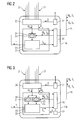
- FIG. 3 a second embodiment of the protective device 13a is shown, which largely corresponds to the first embodiment according to FIG. 2 corresponds, therefore matching components are identified by the same reference numerals.
- the operation of the matching components is the same FIG. 2 already explained operation and should therefore not be explained again at this point, so that only the differences between the two embodiments are highlighted here.
- a second memory area 30 in which a further component of the device software of the protective device 13a is stored in the form of a replacement protection algorithm 31.
- the replacement protection algorithm 31 is specially designed to carry out the protective function as accurately as possible only on the basis of the measured values M a detected at the measuring point 14a by the protective device 13a itself, ie, for example, to make the most accurate possible decision about the operating state present on the line 11a the caused by the parallel line 11 b electrical and / or electromagnetic Couplings to consider.
- the main protection algorithm 25 and the replacement protection algorithm 31 are therefore set up to perform the same protection function, but the main protection algorithm 25 can be based, as it were, on a broader measured value basis.
- a communication monitoring device 32 is provided, which is coupled to the communication device 26 or a component thereof, and the functionality of the communication link 15 between the protective devices 13a and 13b, which also includes the respective communication devices of the protection devices for monitoring, checks and generates a failure signal A. if the communication between the protection devices 13a and 13b is disturbed or interrupted. If the communication monitoring device 32 detects a disturbed or interrupted communication between the two protective devices 13a, 13b, it sends the failure signal A to the control device 22, which then executes the replacement protection algorithm 31 instead of the main protection algorithm 25, since in this case no or no reliable measured values M b and / or signals S b of the neighboring protective device 13b are more available.
- the replacement protection algorithm 31 is specially designed to execute the protection function solely on the basis of the measured values M a acquired by the protection device 13 a itself, this automatic change to the replacement protection algorithm 31, despite a broken or disturbed communication connection 15, provides a sufficiently reliable further function of the protection device 13a be guaranteed.
- a monitoring of the communication connection 15 can take place, for example, by a so-called "hand-shake method" in which the communication monitoring device 32 sends test signals to the communication monitoring device of the other protective device 13b and waits for an acknowledgment signal. If this acknowledgment signal remains longer, a non-functional communication connection 15 is concluded.
- each communication monitoring device can regularly send test signals to the respective other communication monitoring device. If the reception of test signals remains off for a long time, then the respective communication monitoring device closes on a non-functional communication connection.
- the protective function can again by the main protection algorithm 25 under Taking into account the own measured values M a and the measured values M b and / or signals S b are carried out by the adjacent protective device 13b.
- the described parallel line protection system can improve the accuracy, reliability and selectivity of the results in a variety of protection functions mean the main protection algorithm. Some examples of such protection functions are explained in more detail below.
- the protective functions performed by the protective devices 13a, 13b can be, for example, distance protection functions.
- the main protection algorithm executed in the protection device 13a will be explained.
- the main protection algorithm On the input side, the main protection algorithm as measured values M a (cf. FIGS. 2 and 3 ) Current measurements i a and voltage readings u a supplied, which are usually (digital) samples of current and voltage.
- Current measurements i a and voltage readings u a supplied which are usually (digital) samples of current and voltage.
- the main protection algorithm will usually be in the form of a software executed by the control device of the protective device.
- Complex impedance values Z a are calculated from current and voltage measured values which are respectively associated with each other, ie at the same time.
- the calculated impedance values Z a are checked whether the impedance values Z a within a tripping zone lie. If the check reveals that the impedance values Z a lie within the tripping area, an error signal F a is generated.
- the error signal F a preferably indicates not only the mere presence of a fault on the line 11a, but also the phase (s) of the line 11a involved in the fault.
- a protection function is a distance protection function with stabilized deployment area.
- FIG. 4 schematically in a RX diagram a trip area 70, which can be used for a distance protection function, is shown.
- the diagram shown is a complex number plane in which values of the impedance are entered with the real part "resistance” R and the imaginary part "reactance” X.
- the distance protection function calculates corresponding impedance vectors from the measured values recorded by the respective protective device 13a, 13b in the form of current and voltage measured values and places them in the in-field display FIG. 4
- a large trip area 70a is used for the decision of an error on the respective line 11a, 11b.
- an impedance pointer lies within this tripping area, an error is made on the corresponding line and the respective circuit breaker is tripped.
- the protective device of healthy line by coupling effects - especially by load increases and influencing the zero system current of the healthy line - determine an impedance that falls into the trip area and unintentionally to a single-pole or multi-pole shutdown Leading.
- the impedance pointer 71 in the large trip area 70a and would therefore lead to a shutdown of the line.
- the protection device 13a, 13b which detects an error on its line 11a, 11b, sends an error status signal to the respective other protection device 13a, 13b via the communication link, the protective algorithm of the protection device on the healthy line to instead of the large trip area to Evaluation of the impedance pointer temporarily use a reduced trip area 70b.
- the impedance pointer 71 does not fall into the reduced trip area 70b and therefore does not lead to a shutdown of the healthy line.
- the protection device of this line terminates the transmission of the error status signal or sends a cancellation signal via the communication link. This will cause the healthy line protection device to switch back to the large tripping area to evaluate the impedances.
- the example shown merely comprises one triggering area for a single so-called protection zone.
- a plurality of trip areas can be provided, the smallest trip area causes immediate triggering of the circuit breaker concerned, while each larger trip areas can be provided with different scale times, ie triggering takes place in such a larger trip area only when the impedance pointer lingered within the relevant triggering area for more than a predetermined period of time ("stagger time").
- stagger time a predetermined period of time
- FIG. 5 shows a further embodiment of a protection system 80 for the two parallel lines 11a and 11b.
- Reference numeral 82 is an all three phase conductors A, B, C and A ', B', C 'of the two Lines 11a, 11b common electrical ground marked.
- the protective devices 13a, 13b, 13c, 13d are connected to earth 82, but this is explicitly shown only for the protective devices 13b and 13d for reasons of clarity.
- FIG. 5 Unlike the protection system after FIG. 1 are in the embodiment according to FIG. 5 not only the adjacent protection devices (13a and 13b and 13c and 13d) connected to each other via a respective communication link 15, but there is also a further communication link 81 between the protection devices at both ends of each line 11a and 11b (specifically, these are the protection devices 13a and 13c as well as 13b and 13d, the following explanations relate to the protective devices 13b and 13d by way of example only.
- the further communication connection 81 may be both wired and wireless and does not have to exist or be active continuously between the two protection devices 13b and 13d.
- the further communication connection 81 may also be a communication connection of comparatively low data transmission capacity.
- FIG. 5 the first line 11a is completely switched off, eg for maintenance purposes; all poles of the circuit breakers 12a and 12c are in the open position. Later will be referred to that alternatively, the first line 11a can also be completely turned on; all poles of the circuit breakers 12a and 12c are then in the closed position. Although intermediate positions (eg, single-pole open circuit breaker on the first line 11a) may occur, but are not used for the method described below.
- the protective devices 13b and 13d detect the short circuit that has occurred by continuously recording the current and voltage measured values at the respective measuring points 14b and 14d and with these first the impedances of all existing loops, ie the three phase conductor loops (phase A 'to phase B ', phase A' to phase C ', phase B' to phase C ') and the three phase-to-earth loops (phase A' to ground, phase B 'to ground and phase C' to ground).
- the second line 11b is checked for errors.
- the type of fault is determined, ie whether it is a phase-to-phase short circuit or a phase-to-phase short circuit.
- the phases involved in the error are determined.
- the calculated impedance can also be used to deduce the fault location where the short circuit occurred. If there is an error and the fault location is on the second line 11b, the affected phases are disconnected from the rest of the power supply network via the associated power switches 12b, 12d. In FIG. 5 By way of example, the phase C 'of the second line 11b affected by the earth short circuit is opened via the latter shown contacts of the circuit breakers 12b and 12c have been turned off.
- short circuit current flows from the affected phase C 'of the second line 11b via ground 82 back to the respective protection device 13b and 13d.
- the existing earth impedance is usually not known with high accuracy and previously had to be determined by consuming measurements in which the line 11b had to be separated from the rest of the network, or by estimates or readings from tables and entered as parameters in the respective protection device.
- both parallel lines influence each other, so that in this case also a so-called coupling impedance of the lines has to be considered. So far, the value of the coupling impedance can only be estimated by simulations or empirical values or is even completely neglected. Neglecting the coupling impedance, however, can lead to an inaccuracy of up to 40% in terms of fault location. In the following, therefore, a method is to be explained which makes it possible to easily determine setting values for the ground impedance and the coupling impedance.
- the protection device 13b or 13d can determine a fault location value m indicating the fault location. If the line system impedance is known, the additional values for the earth impedance and the coupling impedance must be available.
- the neighboring protection devices 13a and 13b or 13c and 13d exchange operating state signals via the communication connection 15, which indicate whether the respectively adjacent line 11a or 11b is completely switched on or completely switched off.
- the protection device 13b receives an operation state signal indicating that the first line 11a is completely turned off, it may initiate the calculation of the earth impedance adjustment value.
- the initial value for the earth impedance parameter can be, for example, a set value derived from empirical values.
- the experience value can be used to determine a possible initial value such that the ratio of both the real part and the imaginary part between the zero system impedance and the positive sequence impedance of an electrical energy transmission line is usually approximately 1. From this it is possible to estimate a set value for the earth impedance which, while not highly accurate, guarantees the functionality of the protective devices in any case.
- the affected phase C' is first isolated from the rest of the electrical power grid via the power switches 12b and 12d.
- a unidirectional transmission can take place in which, for example, the current and voltage measured values recorded by the protective device 13d are transmitted to the protective device 13b.
- a bidirectional transmission may take place in which both protective devices 13b and 13d transmit their current and voltage measured values to the respective other protective device. Since the earth short circuit is already switched off at this time, the transmission of the respective current and voltage measured values can take place in any desired length of time, so that a connection with a comparatively low data transmission capacity is sufficient for the communication connection 81.
- a so-called two-sided fault location algorithm can then be carried out by one or both protective devices 13b, 13d, with which the fault location at which the earth short circuit has occurred can be determined.
- several possible fault location methods are known from the prior art, for example, in the German patent specification DE 4441334 C1 described two-sided fault location algorithm can be used.
- the protection device in which the current measured values from both ends are present can then be determined using the appropriate mesh equation (3) or ( 4) determine the value of the earth impedance that matches the fault location value m calculated via the two-sided fault location algorithm.
- the earth impedance is calculated which would have resulted in the same fault location alone when using a one-sided fault location by one of the protective devices 13b, 13d as in the two-sided fault location calculation.
- equation (3) for the protective device 13b is changed over in such a way that the following equation results:
- Z e U b - I bL ⁇ m ⁇ Z L - U F m ⁇ I bE
- Some methods for two-sided fault location such as that in the cited patent DE 4441334 C1 described two-sided fault location method, as a result, also provide a value for the voltage drop U F at the fault location, so that this value can be taken directly into the respective calculation equation (6) or (7). If the voltage drop U F at the fault location is not known, it can also be neglected and set to zero without too much influence on the final result.
- the ground impedance Z E can be determined easily .
- the earth impedance calculated in this way can be used hereinafter as the setting value for the "earth impedance" parameter in the protective devices 13b and 13d.
- the protection device 13b receives from its neighboring Protective device 13a during an earth short circuit, an operating state signal indicating a fully turned on first line 11a, it performs in the manner already described with the detected during the ground fault current and voltage readings from both ends of the second line, a two-sided fault location method to the error location value m to determine.
- the current and voltage readings detected during the ground fault at both ends of the second line 11b also be stored for a later determination of the coupling impedance.
- the coupling impedance may then be determined at a later time if there is an accurate earth impedance setting. If a calculation of the setting values for the earth and the coupling impedance takes place in both protective devices 13b and 13d, then the two results for the ground or coupling impedance can be compared with one another. If too large deviations occur between the respective results, then it can be provided that due to the uncertainty of the results, the calculated setting values are discarded and not used as parameters for the protective devices 13b and 13d.
- the method for calculating the setting values for the earth and the coupling impedance is first performed several times by waiting for a few earth short circuits and then an average value is formed from the several calculated setting values. In this case, the respective mean value is then used as the new setting value for the protective devices 13b and 13d.
- a particular advantage of the described method is that the calculation of the setting values for the ground and the coupling impedance is not carried out time-critical, ie, that a first triggering of the respective power switches 12b, 12d takes place in order to separate the fault from the electrical power grid and only Thereafter - depending on the state of the parallel line during the earth short circuit - the calculation of the respective setting takes place.
- the requirements for the further communication link 81 are kept comparatively low, since the transmission time between the protection devices 13b and 13d plays no role.
- the protection devices 13b and 13d can record the current and voltage measurement values, for example, in a non-synchronous manner. In this case, must be used as an algorithm of two-sided fault location Such an algorithm can be used, which synchronizes the current and voltage measurements from the two ends of the line 11b, so to speak, and then calculates the error location value m. Such a method usually requires a continuous communication connection between the protection devices.
- the protective devices 13b and 13d record their current and voltage measured values in a time-synchronized manner, ie that the sampling takes place synchronously in the two protective devices.
- the protection devices 13b and 13d respectively have internal time stamping devices 27 (cf. FIG. 2 ), which are synchronized with each other via an external timer.
- an external timer for example, a GPS satellite can be used, which emits a signal at regular intervals (eg in the second distance), from which an absolute time signal can be extracted.
- the protection devices synchronize their timestamp devices 27 to the external timer by receiving the GPS signals and extracting the time signal from the GPS signal by means of GPS receiver modules (not shown).
- any other externally generated time signal can be used.
- the current and voltage measurement values are assigned a time stamp which indicates the time of their detection, for example, to a microsecond, so that an assignment of the associated current and voltage measurement values from both ends of the line 11b for the two-sided fault location method is possible in a simple manner.
- the time stamp is transmitted together with the respective current and voltage measured values between the protective devices 13b and 13d.
- Such time-stamped current and voltage measurement values also include a merely temporarily existing communication connection between the protection devices is sufficient. If there is no communication connection between the protection devices, then it is also possible in this case to transmit the current and voltage measurement values manually with a data carrier between the protection devices.
- one-sided fault location can be carried out very precisely.
- the exact indication of the fault location can also control the automatic reclosing of mixed lines, partly as overhead line and partially are used as cables are used. This is based on FIG. 6 explained in more detail.
- FIG. 6 shows in highly schematic representation a line 11b, which is designed in the form of a mixed line. Not shown is a parallel extending further line (eg line 11a, see, eg FIG. 5 ).
- a first part 91 of the line 11b is designed as an overhead line, in which the parallel lines are routed over common transmission towers.
- a second part 92 is designed as an underground cable.
- the two-sided fault location is performed as long as a communication link between the protection devices exists at the two measuring points 14b and 14d.
- the fault location can also be determined using the unilateral method with the exact parameters for earth impedance and coupling impedance.
- an automatic reclosing function can be activated in the protective devices 13b, 13d.
- the automatic reclosing function is blocked or deactivated in order not to generate any additional damage or risk due to the renewed reconnection of the current flow to an existing error.
- FIG. 7 shows a further embodiment of a protection system 100 for parallel lines, with which the detection of so-called "intersystem errors" is performed, ie errors, in each of which at least one phase of both lines 11a and 11b are involved.
- intersystem errors ie errors
- FIG. 7 For example, an inter-system error between phase C of the first line 11a and phase A 'of the second line 11b is shown.
- inter-system errors may also affect more than two phases (eg, phases A and B of the first line 11a and phase C 'of the second line 11b).
- the two adjacent protective devices 13a and 13b each use only the measured values of their own lines 11a or 11b for calculating the loop impedances, such intersystem errors can not be correctly identified, so that the risk of a three-pole shutdown (instead of each of a selective single-pole shutdown on both lines 11a and 11b) consists.
- both protection devices 13a, 13b are now able to recognize intersystem faults and selectively switch them off.
- the communication monitoring devices present in the protection devices recognize 32 (s. FIG. 3 ) In the event that the communication link 15 is interrupted or the communication is disturbed, the failure and issue a corresponding failure signal.
- computing power is saved by the fact that the lack of measured values of the parallel line incomplete intersystem error loops are no longer checked.
- erroneous decisions due to the missing measured values from the parallel line are surely avoided when the inter-system error loops are taken out of the check.
- FIGS. 4 to 7 described embodiments of different protective functions can be used individually or in any combination in the protective devices, so that a comprehensive protection of parallel lines is made possible.
Abstract
Description
Die Erfindung betrifft ein Verfahren zum Überwachen eines mehrphasigen elektrischen Energieversorgungsnetzes, wobei ein erstes Schutzgerät mit einer ersten Leitung des Energieversorgungsnetzes zum Erfassen von den Betriebszustand der ersten Leitung charakterisierenden Messwerten in Verbindung steht, wobei das erste Schutzgerät über eine Kommunikationsverbindung mit einem benachbart angeordneten zweiten Schutzgerät verbunden ist, und wobei das zweite Schutzgerät mit einer parallel zu der ersten Leitung verlaufenden zweiten Leitung des Energieversorgungsnetzes zum Erfassen von den Betriebszustand der zweiten Leitung charakterisierenden Messwerten in Verbindung steht, die beiden Schutzgeräte die von ihnen bezüglich ihrer jeweiligen Leitung erfassten Messwerte und/oder von diesen Messwerten abgeleitete Signale an das jeweils andere Schutzgerät übertragen, jedes Schutzgerät zur Ausführung einer Schutzfunktion, insbesondere einer Distanzschutzfunktion, für seine jeweilige Leitung unter Ausführung eines Haupt-Schutzalgorithmus eingerichtet ist, das erste Schutzgerät zur Ausführung seines Haupt-Schutzalgorithmus die an der ersten Leitung erfassten Messwerte sowie die von dem zweiten Schutzgerät empfangenen Messwerte und/oder Signale heranzieht, und das zweite Schutzgerät zur Ausführung seines Haupt-Schutzalgorithmus die an der zweiten Leitung erfassten Messwerte sowie die von dem ersten Schutzgerät empfangenen Messwerte und/oder Signale heranzieht. Die Erfindung betrifft außerdem ein Schutzsystem für ein elektrisches Energieversorgungsnetz sowie ein elektrisches Schutzgerät zur Überwachung einer Leitung eines elektrischen Energieversorgungsnetzes. Ein solches Verfahren, Schutzsystem und Schutzgerät ist beispielsweise aus der
Zur Überwachung von Leitungen elektrischer Energieversorgungsnetze werden sogenannte Schutzgeräte eingesetzt, um unzulässige Betriebszustände der jeweils überwachten Leitung, die beispielsweise durch Kurzschlüsse oder Erdkurzschlüsse hervorgerufen sein können, zu erkennen und automatisch abzuschalten. Hierzu nimmt das elektrische Schutzgerät üblicherweise Messwerte auf, beispielsweise Strom- und/oder Spannungsmesswerte, die den Betriebszustand der Leitung charakterisieren. Zur Ausführung seiner Schutzfunktion, wertet das Schutzgerät daraufhin die Messwerte unter Ausführung eines sogenannten Schutzalgorithmus, also einer Berechnungs-und/oder logischen Verknüpfungsvorschrift zur Auswertung der aufgenommenen Messwerte, aus und erzeugt in Abhängigkeit vom Ergebnis der Auswertung gegebenenfalls ein Auslösesignal, das einen mit dem Schutzgerät in Verbindung stehenden Leistungsschalter zum Öffnen seiner Schaltkontakte veranlasst, um die fehlerbehaftete Leitung vom übrigen Energieversorgungsnetz abzutrennen.So-called protective devices are used to monitor lines of electrical energy supply networks in order to detect and automatically switch off inadmissible operating states of the respective monitored line, which may be caused by short circuits or earth short circuits, for example. For this purpose, the electrical protection device usually receives measured values, for example current and / or voltage measured values which characterize the operating state of the line. To carry out its protective function, the protective device then evaluates the measured values by executing a so-called protection algorithm, ie a calculation and / or logic operation rule for evaluating the recorded measured values, and generates a trigger signal depending on the result of the evaluation, if necessary, with the protection device causing associated circuit breaker to open its switch contacts to separate the faulty line from the rest of the power grid.
Ein häufig zur Überwachung von Leitungen elektrischer Energieversorgungsnetze eingesetzter Schutzalgorithmus arbeitet nach dem sogenannten Distanzschutzverfahren, bei dem aus Strom- und Spannungsmesswerten in einer komplexen Zahlenebene liegende Impedanzwerte berechnet werden und überprüft wird, ob die Impedanzwerte innerhalb eines - auch als Auslösepolygon bezeichneten - vorgegebenen Auslösebereiches liegen. Sofern die Impedanzwerte innerhalb dieses vorgegebenen Auslösebereiches liegen, stellt das Distanzschutzgerät einen unzulässigen Betriebszustand an der von ihm überwachten Leitung des elektrischen Energieversorgungsnetzes fest und sendet ein Auslösesignal an einen oder mehrere die Leitung begrenzende Leistungsschalter, um die fehlerhafte Leitung vom restlichen Energieversorgungsnetz zu trennen.A protection algorithm frequently used for monitoring lines of electrical energy supply networks operates according to the so-called distance protection method in which impedance values are calculated from current and voltage measurement values in a complex number plane and it is checked whether the impedance values are within a predetermined trip range, also referred to as trip polygon. If the impedance values are within this predetermined trip range, the distance protection device sets an inadmissible operating state on the line monitored by it of the electrical power grid and sends a trip signal to one or more line limiting power switches to disconnect the faulty line from the rest of the power grid.
In den letzten Jahren haben sich elektrische Schutzgeräte von ausschließlich eigenständig arbeitenden Überwachungsgeräten immer stärker zu sogenannten intelligenten elektronischen Geräten (Intelligent Electronic Devices = IEDs) entwickelt, die mit anderen Schutzgeräten in einem gemeinsamen Kommunikationsnetzwerk datentechnisch vernetzt sind, um eine weitere Verbesserung der Leistungsfähigkeit und der Zuverlässigkeit bei der Überwachung des Energieversorgungsnetzes zu erreichen. So ist beispielsweise aus der internationalen Patentanmeldung
Aufgrund der in den letzten Jahren kontinuierlich gewachsenen Leistungsaufnahme der an ein Energieversorgungsnetz angeschlossenen elektrischen Endverbraucher und der damit einhergehenden stetig ansteigenden Belastung der Versorgungsleitungen des Energieversorgungsnetzes sind die Betreiber von Energieversorgungsnetzen weitgehend dazu übergegangen, sogenannte "Parallelleitungen", also mehrere parallel zueinander entlang einer Energieübertragungsstrecke angeordnete Energieversorgungsleitungen, zu verlegen. Parallelleitungen können beispielsweise durch Verlegen zusätzlicher Übertragungsleitungen entlang bereits bestehender Freileitungsmasten oder durch paralleles Verlegen mehrerer Erdkabel erreicht werden. Hierdurch kann bei verhältnismäßig geringem Installationsaufwand - z.B. durch Mehrfachnutzung bestehender Freileitungsmasten - auf nahezu demselben Raum eine größere Menge elektrischer Energie transportiert werden. Neben der Steigerung der Übertragungskapazität erhöht sich bei Installation von Parallelleitungen auch die Redundanz des Versorgungssystems, da bei einem Ausfall einer der Parallelleitungen die elektrische Energie für einen begrenzten Zeitraum über die andere Parallelleitung übertragen werden kann. Auf diese Weise können Beeinträchtigungen der Versorgungssicherheit für die Endverbraucher möglichst gering gehalten werden.Due to the continuously growing in recent years power consumption of the connected to a power grid electrical end user and the concomitant steadily increasing load on the supply lines of the power grid are the operators of power grids largely moved to so-called "parallel lines", ie several parallel to each other along an energy transmission path arranged energy supply lines to lay. Parallel lines can be achieved, for example, by laying additional transmission lines along existing overhead transmission towers or by laying several underground cables in parallel. As a result, a relatively large amount of electrical energy can be transported in almost the same space at relatively low installation costs - eg by multiple use of existing transmission towers. In addition to the increase in transmission capacity increases when installing parallel lines and the redundancy of the supply system, since in case of failure of one of the parallel lines, the electrical energy can be transmitted over a limited period of time over the other parallel line. In this way, impairments of security of supply for the end user can be kept as low as possible.
Der Erfindung liegt die Aufgabe zugrunde, Zuverlässigkeit und Selektivität von Entscheidungen über Betriebszustände von Parallelleitungen - also parallel zueinander verlaufenden Leitungen eines elektrischen Energieversorgungsnetzes - zu erhöhen.The invention has for its object to increase reliability and selectivity of decisions on operating states of parallel lines - ie parallel lines of an electrical energy supply network.
Zur Lösung dieser Aufgabe wird ein Verfahren der eingangs genannten Art vorgeschlagen, bei dem das zweite Schutzgerät mit einer parallel zu der ersten Leitung verlaufenden zweiten Leitung des Energieversorgungsnetzes zum Erfassen von den Betriebszustand der zweiten Leitung charakterisierenden Messwerten in Verbindung steht, die beiden Schutzgeräte die von ihnen bezüglich ihrer jeweiligen Leitung erfassten Messwerte und/oder von diesen Messwerten abgeleitete Signale an das jeweils andere Schutzgerät übertragen, jedes Schutzgerät zur Ausführung einer Schutzfunktion für seine jeweilige Leitung unter Ausführung eines Haupt-Schutzalgorithmus eingerichtet ist, das erste Schutzgerät zur Ausführung seines Haupt-Schutzalgorithmus die an der ersten Leitung erfassten Messwerte sowie die von dem zweiten Schutzgerät empfangenen Messwerte und/oder Signale heranzieht, und das zweite Schutzgerät zur Ausführung seines Haupt-Schutzalgorithmus die an der zweiten Leitung erfassten Messwerte sowie die von dem ersten Schutzgerät empfangenen Messwerte und/oder Signale heranzieht.To solve this problem, a method of the type mentioned is proposed in which the second protective device is connected to a parallel to the first line extending second line of the power supply network for detecting the operating state of the second line characterizing measured values, the two protective devices of them with respect to their respective line detected measured values and / or derived from these measurements signals to each other protection device, each protection device is designed to perform a protection function for its respective line under execution of a main protection algorithm, the first protection device to execute its main protection algorithm, the measured values detected on the first line and the measured values received from the second protection device and / or The second protection device uses the measured values recorded on the second line as well as the measured values and / or signals received by the first protective device to execute its main protection algorithm.
Erfindungsgemäß ist vorgesehen, dass die Schutzfunktion eine Distanzschutzfunktion umfasst, wobei die Schutzgeräte zur Durchführung der Distanzschutzfunktion mittels des Haupt-Schutzalgorithmus aus den an ihrer jeweiligen Leitung erfassten Messwerten komplexe Impedanzwerte berechnen und ein Fehlersignal erzeugen, wenn die Impedanzwerte innerhalb eines Auslösegebietes liegen. Jedes Schutzgerät übermittelt bei einem einpoligen Fehler auf seiner jeweiligen Leitung ein den Fehler kennzeichnendes Fehlerstatussignal über die Kommunikationsverbindung an das jeweils andere Schutzgerät, und dasjenige Schutzgerät, das das Fehlerstatussignal empfängt, verkleinert das Auslösegebiet zur Bewertung der Impedanzwerte.According to the invention, it is provided that the protective function comprises a distance protection function, wherein the protective devices calculate complex impedance values for the distance protection function by means of the main protection algorithm from the measured values detected on their respective line and generate an error signal if the impedance values lie within a triggering area. Each protection device transmits a fault status signal indicating the fault to the respective other protection device via the communication connection in the case of a single-pole fault on its respective line, and that protection device which receives the fault status signal reduces the trip area to evaluate the impedance values.
Die Schutzgeräte führen zur Überwachung ihrer jeweiligen Leitungen eine Schutzfunktion durch, zu deren Ausführung der Haupt-Schutzalgorithmus abgearbeitet wird. Bei der Schutzfunktion kann es sich bevorzugt um eine Distanzschutzfunktion handeln. Der Haupt-Schutzalgorithmus kann dabei einen oder mehrere Teile der Schutzfunktion betreffen, auch kann die Schutzfunktion durch Ausführung mehrerer Haupt-Schutzalgorithmen verwirklicht werden; Beispiele dafür werden an späterer Stelle genauer erläutert. Für die Durchführung der Erfindung ist es ferner unkritisch, ob in den Schutzgeräten neben der genannten Schutzfunktion, z.B. der Distanzschutzfunktion, noch weitere Schutzfunktionen bereitgestellt werden, z.B. eine Differentialschutzfunktion oder eine Überstromschutzfunktion.The protective devices perform a protective function for monitoring their respective lines, for the execution of which the main protection algorithm is executed. The protective function may preferably be a distance protection function. The main protection algorithm can relate to one or more parts of the protection function, and the protection function can also be implemented by executing a plurality of main protection algorithms; Examples of this will be later Explained in more detail. For the implementation of the invention, it is also uncritical, whether in the protection devices in addition to the mentioned protection function, such as the distance protection function, further protection functions are provided, for example, a differential protection function or an overcurrent protection function.
Der Erfindung liegt die Erkenntnis zugrunde, dass bei parallelen Leitungen eines elektrischen Energieversorgungsnetzes zwischen den Parallelleitungen eine starke elektrische und/oder elektromagnetische Kopplung besteht, die bei einer zuverlässigen Entscheidung über den auf der jeweiligen Parallelleitung vorliegenden Betriebszustand berücksichtigt werden sollte. Die erfindungsgemäße Lösung sieht daher vor, dass zwischen benachbarten Schutzgeräten, von denen ein erstes Schutzgerät einer ersten Leitung zugeordnet ist und ein zweites Schutzgerät einer parallel zu der ersten Leitung verlaufenden zweiten Leitung zugeordnet ist, eine Kommunikationsverbindung besteht, über die diejenigen Messwerte, die jedes Schutzgerät für seine Leitung erfasst hat, und/oder von diesen Messwerten abgeleitete Signale, die z.B. einen Betriebszustand der jeweiligen Leitung angeben oder einen Steuerbefehl für das jeweils andere Schutzgerät umfassen, zur jeweils anderen Leitung übertragen werden.The invention is based on the finding that in parallel lines of an electrical power supply network between the parallel lines a strong electrical and / or electromagnetic coupling exists, which should be taken into account in a reliable decision on the present on the respective parallel line operating condition. The solution according to the invention therefore provides that between neighboring protective devices, of which a first protective device is assigned to a first line and a second protective device is assigned to a second line extending parallel to the first line, there is a communication connection via which those measured values are stored has detected for his line, and / or derived from these measurements signals that eg indicate an operating state of the respective line or comprise a control command for the respective other protection device, are transmitted to each other line.
Bei einem einpoligen Fehler auf der Parallelleitung kann es vorkommen, dass durch eine elektrische Kopplung über die Sammelschiene (insbesondere durch Veränderungen der Nullsystemströme) und/oder eine elektromagnetische Kopplung zwischen den Leitungen Beeinflussungen der gesunden Leitung auftreten, die sich derart auswirken, dass eine von dem Schutzgerät der gesunden Leitung berechnete Impedanz einer oder mehrerer Phasen innerhalb des Auslösegebietes liegt, obwohl auf der betreffenden Phase tatsächlich kein Fehler vorliegt. In einem solchen Fall würde eine Auslösung des Leistungsschalters an der gesunden Leitung eine unnötige Abschaltung der gesunden Leitung bewirken. Um dies zu vermeiden, ist gemäß der beschriebenen Ausführungsform vorgesehen, dass dasjenige Schutzgerät, das auf seiner Leitung einen einpoligen Fehler erkennt, ein den Fehler kennzeichnendes Fehlerstatussignal an das jeweils andere Schutzgerät sendet. Das Schutzgerät, das das Fehlerstatussignal empfängt, kann dann seine Auslösekriterien stabilisieren, indem es das Auslösegebiet verkleinert. Das Fehlerstatussignal kann hierbei eine Angabe, dass ein einpoliger Fehler erkannt worden ist, und eine Angabe, welche Schleife (z.B. eine bestimmte Leiter-Erde-Schleife oder eine Leiter-Leiter-Schleife) von dem Fehler betroffen ist, umfassen. Bei dem Auslösegebiet kann es sich um ein Hauptauslösegebiet (die sogenannte Zone Z1, die ohne Auslöseverzögerung auf eine Impedanz innerhalb des Z1-Auslösegebiets reagiert) und/oder ein Staffelauslösegebiet (z.B. Zonen Z2, Z3 ,..., bei denen die Auslösung des Leitungsschalters um eine bestimmte Staffelzeit verzögert erfolgt) handeln.In the case of a single-pole fault on the parallel line, it may happen that an influence on the healthy line is caused by an electrical coupling via the busbar (in particular by changes in the zero system currents) and / or an electromagnetic coupling between the lines Protective device of the healthy line is calculated impedance of one or more phases within the tripping area, although on the relevant Phase actually no error exists. In such a case, tripping of the circuit breaker on the healthy line would cause an unnecessary shutdown of the healthy line. In order to avoid this, it is provided according to the described embodiment that the protective device which detects a single-pole fault on its line sends a fault status signal characterizing the fault to the respective other protective device. The protection device, which receives the error status signal, can then stabilize its trigger criteria by decreasing the trip area. The error status signal may include an indication that a single-ended fault has been detected and an indication of which loop (eg, a particular phase-to-earth or ladder-to-loop) is affected by the error. The tripping area may be a main tripping area (the so-called zone Z1, which responds without a tripping delay to an impedance within the Z1 tripping area) and / or a squadron tripping area (eg zones Z2, Z3, ...) where tripping of the line switch to be delayed by a certain season).
Als benachbarte Schutzgeräte werden in diesem Zusammenhang solche Schutzgeräte angesehen, die an demselben Ende der Parallelleitungen angeordnet sind. Eines der benachbarten Schutzgeräte ist hierbei der ersten, das andere der zweiten Parallelleitung zugeordnet. Bei mehr als zwei Parallelleitungen sind an jedem Ende entsprechend mehr als zwei benachbarte Schutzgeräte vorhanden, die Erfindung kann entsprechend auch auf mehr als zwei Parallelleitungen angewendet werden.As adjacent protection devices in this context, such protective devices are considered, which are arranged at the same end of the parallel lines. One of the adjacent protective devices is assigned to the first, the other of the second parallel line. With more than two parallel lines, more than two adjacent protection devices are present at each end, and the invention can be applied accordingly to more than two parallel lines.
Ferner können die jeweiligen Schutzgeräte einzelne abgeschlossene Geräte sein oder aber auch durch Gerätegruppen einzelner Geräte gebildet sein (beispielsweise einem Distanzschutzgerät, einer Schaltersteuerung und/oder einer Merging Unit), die gemeinsam eine Schutzfunktion für die jeweilige Leitung ausführen. Der Einfachheit halber wird jedoch in den folgenden Ausführungen jeweils von einem "Schutzgerät" gesprochen.Furthermore, the respective protective devices can be individual closed devices or can also be formed by device groups of individual devices (for example, a distance protection device, a switch control and / or a merging unit), which together perform a protection function for the respective line. For the sake of simplicity, however, in the following statements in each case by a "protective device" is spoken.
Durch Berücksichtigung der an der jeweils eigenen Leitung erfassten Messwerte einerseits und der vom Schutzgerät der jeweils anderen Leitung empfangenen Messwerte und/oder davon abgeleiteten Signale andererseits zur Durchführung einer Schutzfunktion für die eigene (also die von dem jeweiligen Schutzgerät überwachte) Leitung kann eine deutlich genauere - und damit selektivere und zuverlässigere - Entscheidung über den Betriebszustand der Leitung getroffen werden. Da die Messwerte über eine Kommunikationsverbindung zwischen den Schutzgeräten übertragen werden, müssen zwischen den Schutzgeräten keine direkten elektrischen Verbindungsleitungen zur Übertragung der von Strom- und/oder Spannungswandlern an der jeweiligen Leitung abgegebenen und vergleichsweise hohen Sekundärströme oder Sekundärspannungen verlegt werden. So kann eine Information über die Messwerte und/oder Signale der jeweils anderen Leitung sehr sicher zwischen den Schutzgeräten ausgetauscht werden, ohne Gefahr zu laufen, bei versehentlicher Beschädigung einer direkten elektrischen Verbindungsleitung einen Schaden durch hohe Sekundärströme oder -spannungen hervorzurufen.By taking into account the measured values recorded on the respective individual line on the one hand and the measured values received from the respective other line and / or signals derived therefrom on the other hand for carrying out a protective function for the own line (ie the line monitored by the respective protective device), a much more precise and thus more selective and reliable - decision on the operating status of the line are taken. Since the measured values are transmitted via a communication connection between the protective devices, no direct electrical connecting lines for transmitting the comparatively high secondary currents or secondary voltages emitted by current and / or voltage transformers on the respective line and between the protective devices must be laid. Thus, information about the measured values and / or signals of the other line can be exchanged very securely between the protective devices, without running the risk of causing damage by high secondary currents or voltages in the event of accidental damage to a direct electrical connection line.
Eine vorteilhafte Weiterbildung des erfindungsgemäßen Verfahrens sieht vor, dass die erste und die zweite Leitung jeweils dreiphasige Leitungen eines dreiphasigen Energieversorgungsnetzes sind, beide Schutzgeräte jeweils für jede Phase gesondert die Messwerte der jeweiligen Leitung erfassen, und über die Kommunikationsverbindung für jede Phase die entsprechenden Messwerte und/oder von diesen Messwerten abgeleitete Signale übertragen werden.An advantageous further development of the method according to the invention provides that the first and the second line are each three-phase lines of a three-phase power supply network, both protection devices separately record the measured values of the respective line for each phase, and the corresponding connections via the communication connection for each phase Measured values and / or derived from these measurements signals are transmitted.
Auf diese Weise kann die Überwachung der parallelen Leitungen phasenselektiv, d. h. für jede der drei Phasen des Energieversorgungsnetzes getrennt, durchgeführt werden, so dass beispielsweise bei einem Fehler, von dem nur eine Phase betroffen ist, selektiv nur eine Abschaltung der fehlerbehafteten Phase erfolgt.In this way, the monitoring of the parallel lines can be phase selective, i. H. be performed separately for each of the three phases of the power grid, so that, for example, in an error of which only one phase is affected, selectively only a shutdown of the faulty phase takes place.
Eine weitere vorteilhafte Ausbildung des erfindungsgemäßen Verfahrens sieht vor, dass beide Schutzgeräte eine Zeitstempeleinrichtung aufweisen, mit der den an der jeweiligen Leitung erfassten Messwerten jeweils ein den Zeitpunkt ihrer Erfassung angebender Zeitstempel zugeordnet wird, und gemeinsam mit den über die Kommunikationsverbindung übertragenen Messwerten jeweils die zugehörigen Zeitstempel übermittelt werden.A further advantageous embodiment of the method according to the invention provides that both protection devices have a time stamp device with which the measured values recorded on the respective line are each assigned a time stamp indicating the time of their detection, and together with the measured values transmitted via the communication connection, in each case the associated time stamps be transmitted.
Auf diese Weise können die erfassten Messwerte mit einem ihren genauen Erfassungszeitpunkt angebenden Zeitstempel versehen werden, so dass ein Vergleich und eine Verarbeitung der zu einem bestimmten Zeitpunkt von unterschiedlichen Schutzgeräten aufgenommenen Messwerte einfach möglich ist.In this way, the acquired measured values can be provided with a time stamp indicating their exact detection time, so that it is easy to compare and process the measured values recorded by different protective devices at a particular time.
Eine weitere vorteilhafte Ausbildung des erfindungsgemäßen Verfahrens sieht ferner vor, dass beide Schutzgeräte jeweils eine Kommunikationsüberwachungseinrichtung aufweisen, die die Funktionstüchtigkeit der Kommunikationsverbindung überwacht und ein Ausfallsignal abgibt, wenn die Funktionstüchtigkeit der Kommunikationsverbindung nicht gewährleistet ist, und von den Schutzgeräten bei vorliegendem Ausfallsignal zur Ausführung der Schutzfunktion für ihre jeweilige Leitung ein von dem Haupt-Schutzalgorithmus verschiedener Ersatz-Schutzalgorithmus verwendet wird, der nur die an der jeweils eigenen Leitung erfassten Messwerte, nicht aber die von dem jeweils anderen Schutzgerät empfangenen Messwerte und/oder Signale heranzieht.A further advantageous embodiment of the method according to the invention further provides that both protection devices each have a communication monitoring device that monitors the functionality of the communication link and outputs a failure signal when the functionality of the communication link is not guaranteed, and of the protection devices in the present failure signal to perform the protection function for their respective line one of the main protection algorithm uses a different substitute protection algorithm, which uses only the measured values recorded on its own line but not the measured values and / or signals received by the respective other protective device.
Hierdurch kann erreicht werden, dass im Falle fehlender Funktionstüchtigkeit der Kommunikationsverbindung zwischen den beiden Schutzgeräten, beispielsweise aufgrund einer mechanischen Zerstörung einer Kommunikationsleitung zwischen den Schutzgeräten, die Überwachung der jeweiligen Leitung mit einem Ersatz-Schutzalgorithmus durchgeführt wird, der speziell dazu ausgebildet ist, die Schutzfunktion lediglich anhand der Messwerte von der eigenen Leitung durchzuführen. Hierdurch kann vermieden werden, dass die Schutzfunktion aufgrund der dann fehlenden Messwerte und/oder Signale des jeweils anderen Schutzgerätes zu fehlerhaften Entscheidungen über den Betriebszustand der jeweiligen Leitung führt. Somit ist bei dieser Weiterbildung des erfindungsgemäßen Verfahrens für den Betreiber eines elektrischen Energieversorgungsnetzes immer ein möglichst optimaler Schutz des Energieversorgungsnetzes gewährleistet. Konkret bedeutet dies, dass für den Betreiber eines Energieversorgungsnetzes, der für Parallelleitungen ein bestehendes Schutzsystem betreibt, das keine Anwendung des erfindungsgemäßen Verfahrens vorsieht, bei einer Aufrüstung des Schutzsystems zur Durchführung des erfindungsgemäßen Verfahrens keine Verschlechterung zum bisherigen Zustand eintreten kann. Bei bestehender Kommunikationsverbindung tritt nämlich durch Anwendung des Haupt-Schutzalgorithmus eine Verbesserung der Überwachung ein, während bei gestörter Übertragung über die Kommunikationsverbindung durch Anwendung des Ersatz-Schutzalgorithmus sozusagen auf den Status Quo zurückgeschaltet wird und damit keine Verschlechterung der Überwachung stattfindet.In this way, it can be achieved that, in the event of lack of proper functioning of the communication connection between the two protection devices, for example due to mechanical destruction of a communication line between the protection devices, the monitoring of the respective line is performed with a replacement protection algorithm, which is specially designed to protect only to carry out on the basis of the measured values of the own line. In this way, it can be avoided that the protective function leads to erroneous decisions about the operating state of the respective line due to the then missing measured values and / or signals of the respective other protective device. Thus, in this embodiment of the method according to the invention for the operator of an electrical power supply network always the best possible protection of the power grid guaranteed. Specifically, this means that for the operator of a power supply network, which operates an existing protection system for parallel lines, which does not provide application of the method according to the invention can not deteriorate to the previous state in an upgrade of the protection system for performing the method according to the invention. Namely, in the case of an existing communication connection, the use of the main protection algorithm results in an improvement of the monitoring, while in the case of disturbed transmission over the communication connection by applying the replacement protection algorithm, the status quo returns as it were and there will be no deterioration of surveillance.
Hierfür kann beispielsweise vorgesehen sein, dass beide Schutzalgorithmen, also der Haupt-Schutzalgorithmus und der Ersatz-Schutzalgorithmus parallel zueinander durchgeführt werden und durch die Überwachung der Kommunikationsverbindung lediglich entschieden wird, welche Ergebnisse verwendet werden sollen. In diesem Fall werden bei funktionstüchtiger Kommunikationsverbindung die Ergebnisse des Haupt-Schutzalgorithmus, bei gestörter Kommunikationsverbindung die Ergebnisse des Ersatz-Schutzalgorithmus verwendet. Hierdurch kann eine nahtlose Umschaltung zwischen den beiden Schutzalgorithmen gewährleistet werden.For this purpose, it may be provided, for example, that both protection algorithms, that is to say the main protection algorithm and the replacement protection algorithm, are carried out in parallel, and the only way to decide which results are to be used is by monitoring the communication connection. In this case, the results of the main protection algorithm are used in the case of a functional communication connection, and the results of the replacement protection algorithm in the case of a disturbed communication connection. This ensures seamless switching between the two protection algorithms.
Das erfindungsgemäße Verfahren kann bei verschiedenen Schutzfunktionen zur Steigerung der Zuverlässigkeit und Selektivität eingesetzt werden.The inventive method can be used in various protective functions to increase the reliability and selectivity.
Gemäß einer weiteren vorteilhaften Ausführungsform ist vorgesehen, dass jedes Schutzgerät nach Beendigung eines einpoligen Fehlers auf seiner jeweiligen Leitung die Übertragung des Fehlersignals beendet oder ein das Ende des Fehlers kennzeichnendes Aufhebungssignal über die Kommunikationsverbindung an das jeweils andere Schutzgerät übermittelt, und dasjenige Schutzgerät, das die Beendigung des übertragenen Fehlersignals erkennt oder das Aufhebungssignal empfängt, das Auslösegebiet zur Bewertung der Impedanzwerte wieder vergrößert.According to a further advantageous embodiment, it is provided that each protective device terminates the transmission of the error signal after termination of a single-pole fault on its respective line or transmits the end of the error characterizing cancellation signal via the communication link to the respective other protection device, and that protection device, the termination detects the transmitted error signal or receives the cancellation signal, the trip area for the evaluation of the impedance values increases again.
Bei dieser Ausführungsform kann sehr schnell wieder auf das ursprüngliche Auslösegebiet zurückgeschaltet werden, sobald der einpolige Fehler auf der Parallelleitung beendet ist. Eine weitere vorteilhafte Ausführungsform des erfindungsgemäßen Verfahrens sieht vor, dass die Schutzfunktion eine Distanzschutzfunktion umfasst, wobei die Schutzgeräte zur Durchführung der Distanzschutzfunktion mittels des Haupt-Schutzalgorithmus aus den an ihrer jeweiligen Leitung erfassten Messwerten komplexe Impedanzwerte berechnen und ein Fehlersignal erzeugen, wenn die Impedanzwerte innerhalb eines Auslösegebietes liegen. Die Schutzgeräte tauschen untereinander Betriebsstatussignale aus, die zumindest angeben, ob die von dem jeweiligen Schutzgerät überwachte Leitung komplett eingeschaltet oder komplett ausgeschaltet ist. Während eines einpoligen Fehlers auf der eigenen Leitung speichert das entsprechende Schutzgerät einen Verlauf von Strom- und Spannungsmesswerten ab und überprüft das Betriebsstatussignal des benachbarten Schutzgeräts. Sofern die Prüfung ergibt, dass die parallele Leitung komplett ausgeschaltet ist, empfängt das Schutzgerät, das den Fehler auf seiner Leitung erkannt hat, von einem am anderen Ende derselben Leitung angeordneten weiteren Schutzgerät, das ebenfalls die an seinem Ende während des Fehlers erfassten Strom- und Spannungsmesswerte abgespeichert hat, diese abgespeicherten Strom- und Spannungsmesswerte und berechnet mit den empfangenen und den eigenen abgespeicherten Strom- und Spannungsmesswerten einen Fehlerort, der angibt, an welcher Stelle der Leitung der Fehler aufgetreten ist. Das Schutzgerät bestimmt anhand des berechneten Fehlerortes einen Wert für eine Erdimpedanz, mit dem bei einer Bestimmung des Fehlerortes allein anhand der eigenen abgespeicherten Strom- und Spannungsmesswerte derselbe Fehlerort bestimmt worden wäre wie unter Verwendung der Strom- und Spannungsmesswerte von beiden Enden der Leitung, und stellt den berechneten Wert für die Erdimpedanz als Parameter für die Erdimpedanz zur Verfügung.In this embodiment can be switched back very quickly to the original trip area once the unipolar fault is terminated on the parallel line. A further advantageous embodiment of the method according to the invention provides that the protective function comprises a distance protection function, wherein the protective devices calculate complex impedance values for the distance protection function by means of the main protection algorithm from the measured values recorded on their respective line and generate an error signal if the impedance values within one Trip area lie. The protection devices exchange operating status signals with one another, which at least indicate whether the line monitored by the respective protective device is completely switched on or completely switched off. During a single-pole fault on its own line, the corresponding protection device stores a course of current and voltage measured values and checks the operating status signal of the adjacent protection device. If the test reveals that the parallel line is completely switched off, the protection device which has detected the fault on its line receives from a further protection device arranged at the other end of the same line, which also detects the current and current detected at its end during the fault Stored voltage readings, these stored current and voltage measurements and calculated with the received and its own stored current and voltage readings a fault location indicating at which point of the line the error has occurred. The protection device determines from the calculated fault location a value for an earth impedance with which the same fault location would have been determined in a determination of the fault location solely on the basis of its own stored current and voltage measured values as using the current and voltage measured values from both ends of the line the calculated value for the earth impedance as a parameter for the earth impedance.
Ein ähnliches Verfahren zur Ermittlung der Erdimpedanz bei Einzelleitungen ist bereits aus der
Nunmehr kann durch Nutzung der Erfindung auch bei Parallelleitungen durch eine möglichst genaue Ermittlung des Parameters für die Erdimpedanz, den die Distanzschutzfunktion zur Berechnung der möglichen Erdfehlerschleifen (z.B. Phase A - Erde, Phase B - Erde, Phase C - Erde) benötigt, die Distanzschutzfunktion deutlich verbessert werden. Üblicherweise müssen solche Werte für die Erdimpedanz nämlich entweder durch aufwendige Messungen einmalig bestimmt werden oder es werden lediglich (vergleichsweise ungenaue) Erfahrungs- oder Tabellenwerte für die Erdimpedanz angesetzt.Now, by using the invention even with parallel lines by a very accurate determination of the parameter for the earth impedance, the distance protection function to calculate the possible Erdfehlerschleifen (eg, phase A - earth, phase B - earth, phase C - earth) needed, the distance protection function clearly be improved. Usually, such values for the earth impedance must be determined once either by complex measurements or only (comparatively inaccurate) empirical or table values for the earth impedance are used.
Dagegen kann mit der hier vorgestellten Methode der Wert für die Erdimpedanz vergleichsweise genau und ohne die Notwendigkeit aufwändiger Messapparaturen bestimmt werden. Er beruht nämlich auf der Berechnung des konkreten Fehlerortes mittels eines zweiseitigen Fehlerortungsverfahrens, also einer Methode, bei der mit Messwerten von beiden Enden der fehlerbehafteten Leitung der Fehlerort bestimmt wird. Solche zweiseitigen Verfahren liefern deutlich genauere Ergebnisse als einseitige Fehlerortungsverfahren, bei denen nur die Messwerte eines Endes der Leitung zugrunde gelegt werden. Nachdem wie beschrieben ein genauer Wert für die Erdimpedanz ermittelt worden ist, kann - neben einer besseren Unterscheidung von internen und externen Fehlern und damit einer Erhöhung der Selektivität der Distanzschutzfunktion - auch mittels eines einseitigen Fehlerortungsverfahrens ein vergleichsweise genauer Fehlerort bestimmt werden.On the other hand, with the method presented here, the value for the earth impedance can be determined comparatively accurately and without the necessity of elaborate measuring equipment. It is based on the calculation of the specific fault location by means of a two-sided fault location method, ie a method in which the fault location is determined with measured values from both ends of the faulty line. Such two-sided methods yield significantly more accurate results than one-sided error locating methods, in which only the measured values of one end of the line are used. After an exact value for the earth impedance has been determined as described, a comparatively precise fault location can also be determined-besides a better distinction between internal and external errors and thus an increase in the selectivity of the distance protection function-also by means of a one-sided fault location method.
In diesem Zusammenhang wird es als eine vorteilhafte Weiterbildung angesehen, wenn, sofern die Prüfung ergibt, dass die andere Leitung komplett eingeschaltet ist, das Schutzgerät, das den Fehler auf seiner Leitung erkannt hat, von dem am anderen Ende derselben Leitung angeordneten weiteren Schutzgerät, das die an seinem Ende während des Fehlers erfassten Strom- und Spannungsmesswerte abgespeichert hat, diese abgespeicherten Strom- und Spannungsmesswerte empfängt und mit den empfangenen und den eigenen abgespeicherten Strom- und Spannungsmesswerten einen Fehlerort berechnet, der angibt, an welcher Stelle der Leitung der Fehler aufgetreten ist. Das Schutzgerät bestimmt anhand des berechneten Fehlerortes und des bereitgestellten Parameters für die Erdimpedanz einen Wert für eine Koppelimpedanz, mit dem bei einer Bestimmung des Fehlerortes allein anhand der eigenen abgespeicherten Strom- und Spannungsmesswerte derselbe Fehlerort bestimmt worden wäre wie unter Verwendung der Strom- und Spannungsmesswerte von beiden Enden der Leitung. Der berechnete Wert wird für die Koppelimpedanz in dem Schutzgerät als Parameter für die Koppelimpedanz zur Verfügung gestellt.In this context, it is regarded as an advantageous development, if, if the test shows that the other line is completely turned on, the protection device that has detected the error on his line, from the arranged at the other end of the same line further protection device, the has stored the current and voltage readings collected at the end during the fault, receives these stored current and voltage readings, and calculates, with the received and stored current and voltage readings, a fault location indicating at which point of the lead the fault has occurred , The protection device determines from the calculated fault location and the provided earth impedance parameter a value for a coupling impedance with which the same fault location would have been determined in a determination of the fault location solely on the basis of its own stored current and voltage measurement values as using the current and voltage measurement values of both ends of the pipe. The calculated value is provided for the coupling impedance in the protection device as a parameter for the coupling impedance.
Auf diese Weise lässt sich auch die durch elektrische und/oder elektromagnetische Beeinflussung der Parallelleitungen untereinander entstehende Koppelimpedanz vergleichsweise genau bestimmen. Diese Koppelimpedanz geht in die Berechnung der möglichen Fehlerschleifen zusätzlich ein und stellt, wenn beide Parallelleitungen eingeschaltet sind, einen nicht zu vernachlässigenden Anteil der Distanzschutzberechnung dar. Auf die beschriebene Weise kann die Koppelimpedanz, für die bisher lediglich Erfahrungswerte herangezogen werden, vergleichsweise genau bestimmt werden, da sie wiederum auf der Bestimmung des Fehlerortes mittels der (genauen) zweiseitigen Fehlerortungsmethode beruht. Der zuvor bereits berechnete genaue Wert für die Erdimpedanz wird zur Bestimmung der Koppelimpedanz herangezogen.In this way, the coupling impedance arising from one another through electrical and / or electromagnetic influencing of the parallel lines can also be determined comparatively accurately. This coupling impedance is additionally included in the calculation of the possible error loops and, if both parallel lines are switched on, represents a non-negligible proportion of the distance protection calculation. In the manner described, the coupling impedance, for which only empirical values have hitherto been used, can be determined comparatively accurately, because it in turn is based on the determination of the fault location using the (exact) two-sided fault location method. The previously calculated exact Value for earth impedance is used to determine the coupling impedance.
In diesem Zusammenhang besteht eine weitere vorteilhafte Weiterbildung des erfindungsgemäßen Verfahrens darin, dass bei einer Leitung, die teilweise als Freileitung und teilweise als Kabel ausgeführt ist, entweder unter Verwendung der Strom- und Spannungsmesswerte vom anderen Ende der Leitung oder lediglich anhand der eigenen gespeicherten Strom- und Spannungsmesswerte und der ermittelten Parameter für die Erdimpedanz und die Koppelimpedanz eine Bestimmung des Fehlerortes durchgeführt wird, und, sofern der Fehler auf dem als Freileitung ausgeführten Teil der Leitung liegt, eine automatische Wiedereinschaltung aktiviert wird, die bewirkt, dass der zur Abschaltung des Fehlers geöffnete Leistungsschalter nach Abwarten einer Wartezeit wieder geschlossen wird, während, sofern der Fehler auf dem als Kabel ausgeführten Teil der Leitung liegt, die automatische Wiedereinschaltung blockiert wird.In this context, a further advantageous development of the method according to the invention is that with a line that is partially designed as an overhead line and partly as a cable, either using the current and voltage readings from the other end of the line or only on the basis of their own stored current and voltage readings and the determined parameters for the earth impedance and the coupling impedance a determination of the fault location is performed, and, if the fault is on the part of the line designed as an overhead line, an automatic reclosing is activated, which causes the one to open the fault After waiting for a waiting time, the circuit breaker is closed again, while if the fault is on the cable part of the line, automatic reclosing is blocked.
Im Falle eines Fehlers auf einer solchen "gemischten" Leitung, also einer teils als Freileitung, teils als unterirdisch verlegtes Kabel ausgeführten Leitung, muss nämlich hinsichtlich einer automatischen Wiedereinschaltung unterschieden werden, auf welchem der Teile (Freileitung oder Kabel) der Fehler aufgetreten ist. Während sich auf einer Freileitung ein Fehler oft nach einer kurzen Abschaltung der fehlerbehafteten Phase von selbst klärt (z.B. weil der Fehler auf einer temporären Berührung durch einen Baum oder auf Einwirkung durch Tiere beruhte), ist ein Fehler in einem Kabel üblicherweise auf eine Beschädigung des Kabels zurückzuführen, so dass eine automatische Wiedereinschaltung eher eine zusätzliche Gefährdung an der Beschädigungsstelle bedeuten würde.In the case of a fault on such a "mixed" line, that is partly designed as an overhead line, partly as underground laid cable, namely, it must be distinguished in terms of automatic reclosing on which of the parts (overhead line or cable) the error has occurred. While on an overhead line an error often clears itself after a brief shutdown of the faulted phase (eg, because the fault was due to a temporary tree touch or animal exposure), a fault in a cable is usually a cable damage attributed, so that automatic reclosure rather an additional Endangerment at the point of damage would mean.
Sofern durch eine genaue Fehlerortung, sei es durch ein zweiseitiges Verfahren oder eine einseitige Fehlerortung mit den genau berechneten Werten für Erd- und die Koppelimpedanz, eine Unterscheidung ermöglicht wird, auf welchem Teil der Leitung der Fehler liegt, kann entsprechend beim Freileitungsteil eine automatische Wiedereinschaltung aktiviert und beim Kabelteil eine solche blockiert werden.If a precise fault location, be it by a two-sided method or a one-sided fault location with the precisely calculated values for earth and the coupling impedance, a distinction is made possible on which part of the line is the error, can be activated according to the overhead line part automatic reclosing and the cable part such a blocked.
In diesem Zusammenhang wird es zudem als vorteilhaft angesehen, wenn im Falle einer funktionsfähigen Kommunikationsverbindung zwischen den Schutzgeräten an beiden Enden der von dem Fehler betroffenen Leitung die Bestimmung des Fehlerortes anhand der Strom- und Spannungsmesswerte von beiden Enden der Leitung durchgeführt wird, während im Falle einer gestörten oder unterbrochenen Kommunikationsverbindung zwischen den Schutzgeräten an beiden Enden der von dem Fehler betroffenen Leitung die Bestimmung des Fehlerortes lediglich anhand der eigenen gespeicherten Strom- und Spannungsmesswerte und der ermittelten Parameter für die Erd- und die Koppelimpedanz durchgeführt wird.In this connection, it is also considered advantageous if, in the case of a functional communication connection between the protection devices at both ends of the line affected by the fault, the fault location is determined on the basis of the current and voltage measurements from both ends of the line, while in the case of faulty or interrupted communication connection between the protection devices at both ends of the line affected by the fault, the determination of the fault location is carried out only on the basis of their own stored current and voltage measured values and the determined parameters for the earth and the coupling impedance.
Da nämlich üblicherweise auch bei genau berechneten Werten für die Erd- und die Koppelimpedanz durch das zweiseitige Fehlerortungsverfahren genauere Werte für den Fehlerort ermitteln werden, sollte dieses - im Falle einer bestehenden Kommunikationsverbindung zwischen den beiden Leitungsenden - bevorzugt verwendet werden. Lediglich beim Ausfall dieser Kommunikationsverbindung oder gestörter bzw. zu langsamer Übertragung der Messwerte kann auf die einseitige Fehlerortung mit den genauen Werten für Erd- und Koppelimpedanz zurückgegriffen werden.Since, in the case of precisely calculated values for ground and coupling impedance, more accurate values for the fault location are usually determined by the two-sided fault location method, this should preferably be used in the case of an existing communication link between the two line ends. Only in case of failure of this communication connection or disturbed or too slow transmission of the measured values can on the one-sided fault location the exact values for ground and coupling impedance are used.
Eine weitere Ausführungsform des erfindungsgemäßen Verfahrens sieht vor, dass die Schutzfunktion eine Distanzschutzfunktion umfasst, wobei die Schutzgeräte zur Durchführung der Distanzschutzfunktion mittels des Haupt-Schutzalgorithmus aus den an ihrer jeweiligen Leitung erfassten Messwerten komplexe Impedanzwerte berechnen und ein Fehlersignal erzeugen, wenn die Impedanzwerte innerhalb eines Auslösegebietes liegen. Zwischen den benachbarten Schutzgeräten werden hinsichtlich der einzelnen Phasen der jeweils eigenen Leitung erfasste Messwerte über die Kommunikationsverbindung ausgetauscht. Die Schutzfunktion des jeweiligen Schutzgeräts führt zur Auswahl, welche Phasen von dem Fehler betroffen sind, eine Impedanzmessung bezüglich einerseits der Leiter-Leiter-Schleifen und der Leiter-Erde-Schleifen der jeweils eigenen Leitung und andererseits bezüglich durch Kombination von Phasen beider Leitungen entstehender gemischter Leiter-Leiter-Schleifen durch und schließt durch Vergleich der Schleifen-Impedanzen untereinander und/oder mit einem jeweiligen Schleifen-Impedanzschwellenwert auf die jeweils fehlerbehaftete Schleife.A further embodiment of the method according to the invention provides that the protective function comprises a distance protection function, wherein the protective devices calculate complex impedance values for the distance protection function by means of the main protection algorithm from the measured values recorded on their respective line and generate an error signal if the impedance values within a trip area lie. Between the adjacent protection devices, measured values acquired with regard to the individual phases of the respective individual line are exchanged via the communication connection. The protection function of the respective protection device leads to the choice of which phases are affected by the fault, an impedance measurement with respect to the conductor-conductor loops and the conductor-earth loops of the respective separate line and on the other hand to mixed conductors resulting from the combination of phases of both lines Conductor loops and closes by comparing the loop impedances with each other and / or with a respective loop impedance threshold to the respective faulty loop.
Hierdurch können neben Fehlern, von denen jeweils nur eine der Leitungen betroffen ist, auch sogenannte Intersystemfehler ("Inter-System-Fault"), bei denen ein Fehler zwischen Phasen beider Leitungen auftritt, erkannt und selektiv abgeschaltet werden.As a result, in addition to errors, of which only one of the lines is affected, so-called inter-system fault ("inter-system fault"), in which an error occurs between phases of both lines, can be detected and selectively switched off.
Die oben genannte Aufgabe wird außerdem durch ein Schutzsystem zum Überwachen eines elektrischen Energieversorgungsnetzes gelöst mit einem ersten Schutzgerät, das mit einer ersten Leitung des Energieversorgungsnetzes zum Erfassen von den Betriebszustand der ersten Leitung charakterisierenden Messwerten in Verbindung steht, wobei das erste Schutzgerät über eine Kommunikationsverbindung mit einem benachbart angeordneten zweiten Schutzgerät verbunden ist, und wobei das zweite Schutzgerät mit einer parallel zu der ersten Leitung verlaufenden zweiten Leitung des Energieversorgungsnetzes zum Erfassen von den Betriebszustand der zweiten Leitung charakterisierenden Messwerten in Verbindung steht, die beiden Schutzgeräte die von ihnen bezüglich ihrer jeweiligen Leitung erfassten Messwerte und/oder von diesen Messwerten abgeleitete Signale an das jeweils andere Schutzgerät übertragen, jedes Schutzgerät zur Ausführung einer Schutzfunktion, insbesondere einer Distanzschutzfunktion, für seine jeweilige Leitung unter Ausführung eines Haupt-Schutzalgorithmus eingerichtet ist, das erste Schutzgerät zur Ausführung seines Haupt-Schutzalgorithmus die an der ersten Leitung erfassten Messwerte sowie die von dem zweiten Schutzgerät empfangenen Messwerte und/oder Signale heranzieht, und das zweite Schutzgerät zur Ausführung seines Haupt-Schutzalgorithmus die an der zweiten Leitung erfassten Messwerte sowie die von dem ersten Schutzgerät empfangenen Messwerte und/oder Signale heranzieht. Erfindungsgemäß ist bei einem solchen Schutzsystem vorgesehen, dass die Steuereinrichtung des jeweiligen Schutzgeräts dazu eingerichtet ist, ein Verfahren gemäß einem der Ansprüche 1 bis 10 auszuführen.The above object is further achieved by a protection system for monitoring an electrical power supply network having a first protection device connected to a first line of the power supply network for detecting the operating state the first line characterizing measured values is connected, wherein the first protection device is connected via a communication link with an adjacently arranged second protection device, and wherein the second protection device with a parallel to the first line extending second line of the power supply network for detecting the operating state of the second line characterizing measured values, the two protective devices transmit the measured values detected by them with respect to their respective line and / or signals derived from these measured values to the respective other protective device, each protective device for carrying out a protective function, in particular a distance protection function, for its respective line under execution of a main protection algorithm, the first protection device for carrying out its main protection algorithm receives the measured values detected on the first line as well as those of the second protection device and the second protection device uses the measured values recorded on the second line as well as the measured values and / or signals received by the first protective device to execute its main protection algorithm. According to the invention, it is provided in such a protection system that the control device of the respective protection device is set up to carry out a method according to one of
Vorteilhafterweise handelt es sich bei der Kommunikationsverbindung zwischen den beiden Schutzgeräten um eine Breitband-Datenverbindung, die beispielsweise durch eine Glasfaserleitung gebildet sein kann. Hierdurch wird eine bidirektionale Übertragung der Messwerte nahezu in Echtzeit, also ohne signifikante Zeitverzögerung nach ihrer Erfassung, ermöglicht. Eine weitere vorteilhafte Ausführungsform des erfindungsgemäßen Schutzsystems sieht vor, dass die erste und die zweite Leitung jeweils dreiphasige Leitungen eines dreiphasigen Energieversorgungsnetzes sind, beide Schutzgeräte jeweils eine Messwerterfassungseinrichtung aufweisen, die dazu eingerichtet ist, für jede Phase gesondert die Messwerte der jeweiligen Leitung zu erfassen, und die Kommunikationseinrichtungen der Schutzgeräte dazu eingerichtet sind, über die Kommunikationsverbindung für jede Phase die entsprechenden Messwerte und/oder Signale zu übertragen.Advantageously, the communication link between the two protection devices is a broadband data connection, which may be formed for example by a glass fiber cable. As a result, bidirectional transmission of the measured values is made possible almost in real time, ie without significant time delay after their detection. A further advantageous embodiment of the protection system according to the invention provides that the first and the second line are each three-phase lines of a three-phase power supply network, both protection devices each having a measured value detection device which is adapted to separately record the measured values of the respective line for each phase, and the communication devices of the protection devices are set up to transmit the corresponding measured values and / or signals for each phase via the communication connection.
Weiterhin kann gemäß einer weiteren vorteilhaften Ausbildung des erfindungsgemäßen Schutzsystems vorgesehen sein, dass beide Schutzgeräte eine Zeitstempeleinrichtung aufweisen, die dazu eingerichtet ist, den an der jeweiligen Leitung erfassten Messwerten jeweils einen den Zeitpunkt ihrer Erfassung angebenden Zeitstempel zuzuordnen, und die Kommunikationseinrichtung dazu eingerichtet ist, gemeinsam mit den über die Kommunikationsverbindung übertragenen Messwerten jeweils die zugehörigen Zeitstempel zu übermitteln.Furthermore, according to a further advantageous embodiment of the protection system according to the invention, it can be provided that both protection devices have a time stamp device which is set up to associate the measured values recorded on the respective line with a time stamp indicating the time of their detection, and the communication device is set up in common in each case transmit the associated time stamps with the measured values transmitted via the communication connection.
Eine weitere vorteilhafte Ausführungsform des erfindungsgemäßen Schutzsystems sieht außerdem vor, dass beide Schutzgeräte jeweils eine Kommunikationsüberwachungseinrichtung aufweisen, die dazu eingerichtet ist, die Funktionstüchtigkeit der Kommunikationsverbindung zu überwachen und ein Ausfallsignal abzugeben, wenn die Funktionstüchtigkeit der Kommunikationsverbindung nicht gewährleistet ist, und die Steuereinrichtung der Schutzgeräte dazu eingerichtet ist, bei vorliegendem Ausfallsignal zur Ausführung der Schutzfunktion für ihre jeweilige Leitung einen von dem Haupt-Schutzalgorithmus verschiedenen Ersatz-Schutzalgorithmus zu verwenden, der nur die an der jeweils eigenen Leitung erfassten Messwerte, nicht aber die von dem jeweils anderen Schutzgerät empfangenen Messwerte und/oder Signale heranzieht.A further advantageous embodiment of the protection system according to the invention also provides that both protection devices each have a communication monitoring device, which is set up to monitor the functionality of the communication link and deliver a failure signal, if the functionality of the communication link is not guaranteed, and the control device of the protection devices is set up to use in the present failure signal to perform the protection function for their respective line a different protection algorithm different from the main protection algorithm, which only the measured values recorded on the respective own line, but not uses the measured values and / or signals received from the respective other protective device.
Die oben genannte Aufgabe wird schließlich auch durch ein elektrisches Schutzgerät zur Überwachung einer ersten Leitung eines elektrischen Energieversorgungsnetzes gelöst mit einer Messwerterfassungseinrichtung, die mit der ersten Leitung des Energieversorgungsnetzes zum Erfassen von den Betriebszustand der ersten Leitung charakterisierenden Messwerten verbindbar ist, und einer Kommunikationseinrichtung, über die eine Kommunikationsverbindung zwischen dem Schutzgerät und einem benachbart zu dem Schutzgerät angeordneten zweiten Schutzgerät herstellbar ist, wobei bei bestehender Kommunikationsverbindung zwischen den Schutzgeräten Messwerte und/oder von diesen Messwerten abgeleitete Signale zwischen den Schutzgeräten übertragen werden, das Schutzgerät (13a) eine Steuereinrichtung aufweist, die zur Ausführung einer Schutzfunktion, insbesondere einer Distanzschutzfunktion, für die erste Leitung unter Ausführung eines Haupt-Schutzalgorithmus eingerichtet ist, wobei das Schutzgerät zur Ausführung seines Haupt-Schutzalgorithmus die an der ersten Leitung erfassten Messwerte sowie die von dem zweiten Schutzgerät empfangenen Messwerte und/oder Signale bezüglich einer parallel zu der ersten Leitung verlaufenden zweiten Leitung heranzieht. Erfindungsgemäß ist vorgesehen, dass die Steuereinrichtung des Schutzgeräts dazu eingerichtet ist, ein Verfahren gemäß einem der Ansprüche 1 bis 10 auszuführen.Finally, the above object is also achieved by an electrical protection device for monitoring a first line of an electrical power supply network with a measured value detection device that can be connected to the first line of the energy supply network for detecting measured values characterizing the operating state of the first line, and a communication device via which a communication connection between the protective device and a second protective device arranged adjacent to the protective device can be produced, wherein measured values and / or signals derived from these measured values are transmitted between the protective devices in the event of an existing communication connection between the protective devices, the protective device (13a) has a control device which is connected to the Execution of a protective function, in particular a distance protection function, is set up for the first line by executing a main protection algorithm, wherein the protective g For carrying out its main protection algorithm, the measured values acquired at the first line and the measured values and / or signals received by the second protective device with respect to a second line running parallel to the first line are used. According to the invention it is provided that the control device of the protective device is adapted to carry out a method according to one of
Eine vorteilhafte Weiterbildung des erfindungsgemäßen Schutzgerätes sieht vor, dass das Schutzgerät eine Kommunikationsüberwachungseinrichtung aufweist, die dazu eingerichtet ist, die Funktionstüchtigkeit der Kommunikationsverbindung zu überwachen und ein Ausfallsignal abzugeben, wenn die Funktionstüchtigkeit der Kommunikationsverbindung nicht gewährleistet ist, und die Steuereinrichtung dazu eingerichtet ist, bei vorliegendem Ausfallsignal zur Ausführung der Schutzfunktion für ihre Leitung einen von dem Haupt-Schutzalgorithmus verschiedenen Ersatz-Schutzalgorithmus zu verwenden, der nur die an der ersten Leitung erfassten Messwerte, nicht aber die von dem zweiten Schutzgerät empfangenen Messwerte und/oder Signale heranzieht.An advantageous development of the protection device according to the invention provides that the protection device has a communication monitoring device which is set up to monitor the functionality of the communication connection and to issue a failure signal if the functionality the communication link is not guaranteed, and the control device is adapted to use in the present failure signal to perform the protection function for their line a different protection algorithm from the main protection algorithm, the only detected on the first line measurements, but not of the measured values and / or signals received by the second protection device.
Die Erfindung wird im Folgenden anhand von Ausführungsbeispielen näher erläutert. Hierzu zeigen
Figur 1- eine schematische Ansicht eines Schutzsystems für Parallelleitungen;
- Figur 2
- eine schematische Ansicht einer Ausführung eines elektrischen Schutzgerätes;
- Figur 3
- eine schematische Ansicht einer weiteren Ausführung eines elektrischen Schutzgerätes;
- Figur 4
- eine schematische Darstellung eines Auslösegebiets für eine Distanzschutzfunktion;
- Figur 5
- eine weitere schematische Ansicht eines Schutzsystems für Parallelleitungen;
- Figur 6
- eine schematische Ansicht einer gemischten Leitung, die teils als Freileitung, teils als Kabel ausgeführt ist; und
- Figur 7
- eine schematische Ansicht eines Schutzsystems zur Erkennung von Intersystemfehlern.
- FIG. 1
- a schematic view of a protection system for parallel lines;
- FIG. 2
- a schematic view of an embodiment of an electrical protection device;
- FIG. 3
- a schematic view of another embodiment of an electrical protection device;
- FIG. 4
- a schematic representation of a trip area for a distance protection function;
- FIG. 5
- another schematic view of a protection system for parallel lines;
- FIG. 6
- a schematic view of a mixed line, which is designed partly as an overhead line, partly as a cable; and
- FIG. 7
- a schematic view of a protection system for the detection of intersystem errors.
Da sich die parallel verlaufenden Leitungen 11a und 11b in räumlicher Nähe zueinander befinden, findet zwischen den beiden Leitungen 11a und 11b eine nicht zu vernachlässigende elektrische und/oder elektromagnetische Beeinflussung statt. Die elektrische Beeinflussung findet hierbei beispielsweise über Sammelschienen statt, mit denen beide Leitungen 11a, 11b in elektrischer Verbindung stehen, während die elektromagnetische Beeinflussung drahtlos infolge der engen Nachbarschaft der Parallelleitungen 11a, 11b auftritt. Eine elektromagnetische Beeinflussung ist insbesondere bei Freileitungen zu berücksichtigen, da unterirdische Kabel üblicherweise abgeschirmt sind. Insbesondere im Fall eines Fehlers auf einer der beiden Leitungen 11a oder 11b, der einen hohen Kurzschlussstrom auf der fehlerbehafteten Leitung hervorruft, tritt hinsichtlich der nicht von dem Fehler betroffenen ("gesunden") Leitung ein deutlicher Kopplungseffekt auf. Ein solcher Kopplungseffekt kann sich - sofern er bei der Durchführung des Haupt-Schutzalgorithmus nicht gesondert berücksichtigt wird - störend auf die Schutzfunktion der gesunden Leitung auswirken, so dass im Extremfall sogar ein ungewolltes Abschalten der gesunden Leitung hervorgerufen werden kann.Since the
Um dies zu vermeiden, sind in dem in
Durch die direkte Berücksichtung der jeweils durch die andere Parallelleitung hervorgerufenen Kopplungseinflüsse kann der Haupt-Schutzalgorithmus genauere Ergebnisse bestimmen, so dass z.B. eine zuverlässigere und selektivere Abschaltung genau derjenigen Phasen der Leitungen 11a bzw. 11b vorgenommen werden kann, die tatsächlich von einem Fehler betroffen sind, während solche Phasen, auf denen lediglich aufgrund der Kopplungseffekte scheinbar unzulässige Betriebszustände erkannt werden, eingeschaltet bleiben.By directly considering the coupling effects produced by the other parallel line, the main protection algorithm can determine more accurate results, so that e.g. a more reliable and selective shutdown of precisely those phases of the
In
Weiterhin kann die Messwerterfassungseinrichtung 20 Analog-Digitalumsetzer aufweisen, die eine Analog-Digital-Umsetzung der von den sekundären Strom- bzw. Spannungswandlern abgegebenen Messsignale unter Bildung digitaler Messwerte Ma vornehmen. Die Messwerterfassungseinrichtung 20 kann ferner digitale Filtereinrichtungen aufweisen, um den Verlauf der so erzeugten digitalen Messwerte Ma einer digitalen Filterung zu unterziehen, beispielsweise um mögliche Störeinflüsse zu entfernen, die bei der Messwerterfassung und/oder -umwandlung aufgetreten sein können, oder um aus den Messwerten komplexe Strom- und Spannungszeiger zu berechnen.Furthermore, the measured-
In einer Ausführungsform kann das Schutzgerät 13a außerdem eine Zeitstempeleinrichtung 27 aufweisen, bei der es sich beispielsweise um einen GPS-Empfänger handeln kann, der ein externes Zeitsignal empfängt und eine mikrosekundengenaue Zeitinformation ZI an die Messwerterfassungseinrichtung 20 abgibt. Anhand dieser Zeitinformation ZI kann eine Zeitstempelung der Messwerte Ma vorgenommen werden, d. h. es kann jedem Messwert Ma eine seinen Erfassungszeitpunkt angebende Zeitinformation ZI zugeordnet werden.In one embodiment, the
Die so erzeugten und gegebenenfalls zeitgestempelten Messwerte Ma werden einer Steuereinrichtung 22 des Schutzgerätes 13a zugeführt, die mit einer Recheneinrichtung 23, beispielsweise einer CPU und/oder einem digitalen Signalprozessor eine Gerätesoftware in Form eines in einem Speicherbereich 24 abgespeicherten Haupt-Schutzalgorithmus 25 durchführt. Der Haupt-Schutzalgorithmus ist dazu eingerichtet, eine Schutzfunktion zur Überwachung der ersten Leitung 11a durchzuführen. Wie in
Das Schutzgerät 13a weist weiterhin eine Kommunikationseinrichtung 26 auf, die über eine Kommunikationsverbindung 15, die als eine drahtgebundene Verbindung (z.B. eine Glasfaserkommunikationsleitung) oder eine drahtlose Verbindung (z.B. Funk, WLAN) ausgebildet sein kann, mit einer entsprechenden Kommunikationseinrichtung des benachbarten Schutzgeräts 13b in Verbindung steht. Über die Kommunikationsverbindung 15 tauschen die beiden Schutzgeräte 13a und 13b Messwerte in der Weise aus, dass die von der Messwerterfassungseinrichtung 20 bereitgestellten Messwerte Ma über die Kommunikationseinrichtung 26 und die Kommunikationsverbindung 15 an das benachbarte Schutzgerät 13b übertragen werden, während die von diesem benachbarten Schutzgerät 13b an der Messstelle 14b der zweiten Leitung 11b erfassten Messwerte Mb über die Kommunikationsverbindung 15 an die Kommunikationseinrichtung 26 des ersten Schutzgeräts 13a übertragen werden. Zusätzlich oder alternativ zu den Messwerten können zwischen den benachbarten Schutzgeräten 13a, 13b auch von den Messwerten an der jeweils eigenen Leitung abgeleitete Signale ausgetauscht werden. Im Schutzgerät 13a werden dazu die eigenen Messwerte Ma der Recheneinrichtung 23 zugeführt, die diese Messwerte Ma auswertet und Signale Sa erzeugt, die z.B. einen Betriebszustand der eigenen Leitung 11a (z.B. Fehler in einem Phasenleiter der Leitung 11a) angeben. Diese Signale werden von der Recheneinrichtung 23 der Kommunikationseinrichtung 26 zugeführt und über die Kommunikationsverbindung 15 an das benachbarte Schutzgerät 13b übertragen. In entsprechender Weise können auch von dem Schutzgerät 13b durch Auswertung der Messwerte Mb Signale Sb erzeugt und an das Schutzgerät 13a übertragen werden.The
Die Kommunikationsverbindung 15 sollte möglichst eine breitbandige Datenübertragung in Vollduplex-Betrieb ermöglichen, so dass die Messwerte Ma und Mb und/oder die Signale Sa, Sb nahezu in Echtzeit, d. h. ohne signifikante Verzögerung nach ihrer Erfassung bzw. Erzeugung, zum jeweils anderen Schutzgerät übermittelt werden.The
Die von der Kommunikationseinrichtung 26 des Schutzgerätes 13a empfangenen Messwerte Mb und/oder Signale Sb des Schutzgerätes 13b werden an die Steuereinrichtung 22 weitergeleitet und, wie in
In
Im Gegensatz zum ersten Ausführungsbeispiel gemäß
Bei dem Ausführungsbeispiel gemäß
Um den Wechsel zwischen dem Haupt-Schutzalgorithmus 25 und dem Ersatz-Schutzalgorithmus 31 möglichst nahtlos durchführen zu können, kann beispielsweise vorgesehen sein, dass beide Schutzalgorithmen ständig parallel durchgeführt werden und je nach Zustand der Kommunikationsverbindung 15 die Ergebnisse des Haupt-Schutzalgorithmus 25 bzw. des Ersatz-Schutzalgorithmus 31 verwendet werden.To perform the change between the
Eine Überwachung der Kommunikationsverbindung 15 kann beispielsweise durch ein sogenanntes "Hand-Shake-Verfahren" erfolgen, bei dem die Kommunikationsüberwachungseinrichtung 32 Testsignale an die Kommunikationsüberwachungseinrichtung des anderen Schutzgerätes 13b sendet und auf ein Quittierungssignal wartet. Bleibt dieses Quittierungssignal länger aus, so wird auf eine nicht funktionstüchtige Kommunikationsverbindung 15 geschlossen. Alternativ kann auch jede Kommunikationsüberwachungseinrichtung regelmäßig Testsignale an die jeweils andere Kommunikationsüberwachungseinrichtung senden. Bleibt der Empfang von Testsignalen längere Zeit aus, so schließt die jeweilige Kommunikationsüberwachungseinrichtung auf eine nicht funktionstüchtige Kommunikationsverbindung.A monitoring of the
Sobald die Kommunikationsüberwachungseinrichtung 32 wieder eine funktionstüchtige Kommunikation zwischen den beiden Schutzgeräten 13a und 13b erkennt, und somit die übertragenen Messwerte Mb und/oder Signale Sb des Schutzgerätes 13b wieder zuverlässig empfangen werden können, kann die Schutzfunktion wieder durch den Haupt-Schutzalgorithmus 25 unter Berücksichtigung der eigenen Messwerte Ma und der Messwerte Mb und/oder Signale Sb vom benachbarten Schutzgerät 13b durchgeführt werden.Once the
Das beschriebene Schutzsystem für Parallelleitungen kann bei einer Vielzahl von Schutzfunktionen eine Verbesserung von Genauigkeit, Zuverlässigkeit und Selektivität der Ergebnisse des Haupt-Schutzalgorithmus bedeuten. Einige Beispiele solcher Schutzfunktionen werden nachfolgend näher erläutert.The described parallel line protection system can improve the accuracy, reliability and selectivity of the results in a variety of protection functions mean the main protection algorithm. Some examples of such protection functions are explained in more detail below.
Wie bereits eingangs erwähnt, kann es sich bei den von den Schutzgeräten 13a, 13b ausgeführten Schutzfunktionen beispielsweise um Distanzschutzfunktionen handeln. Zunächst sei der im Schutzgerät 13a ausgeführte Haupt-Schutzalgorithmus erläutert. Eingangsseitig werden dem Haupt-Schutzalgorithmus als Messwerte Ma (vergleiche
Es werden aus jeweils zusammengehörenden - d.h. zu demselben Zeitpunkt erfassten - Strom- und Spannungsmesswerten komplexe Impedanzwerte Z a berechnet. Die berechneten Impedanzwerte Z a werden daraufhin überprüft, ob die Impedanzwerte Z a innerhalb eines Auslösegebietes liegen. Ergibt die Überprüfung, dass die Impedanzwerte Z a innerhalb des Auslösegebietes liegen, wird ein Fehlersignal Fa erzeugt. Das Fehlersignal Fa gibt hierbei vorzugsweise nicht nur das bloße Vorhandensein eines Fehlers auf der Leitung 11a, sondern auch die an dem Fehler beteiligte(n) Phase(n) der Leitung 11a an.Complex impedance values Z a are calculated from current and voltage measured values which are respectively associated with each other, ie at the same time. The calculated impedance values Z a are checked whether the impedance values Z a within a tripping zone lie. If the check reveals that the impedance values Z a lie within the tripping area, an error signal F a is generated. The error signal F a preferably indicates not only the mere presence of a fault on the
Eine Ausführungsform einer Schutzfunktion ist eine Distanzschutzfunktion mit stabilisiertem Auslösegebiet. Dazu ist in
Sofern auf einer Leitung allerdings bereits ein einpoliger Fehler vorliegt, kann das Schutzgerät der gesunden Leitung durch Kopplungseffekte - insbesondere durch Lasterhöhungen und eine Beeinflussung des Nullsystemstromes der gesunden Leitung - eine Impedanz bestimmen, die in das Auslösegebiet fällt und ungewollt zu einer einpoligen oder mehrpoligen Abschaltung der Leitung führt. Bei dem Beispiel gemäß
Um dies zu verhindern, ist vorgesehen, dass dasjenige Schutzgerät 13a, 13b, das einen Fehler auf seiner Leitung 11a, 11b erkennt, ein Fehlerstatussignal an das jeweils andere Schutzgerät 13a, 13b über die Kommunikationsverbindung sendet, das den Schutzalgorithmus des Schutzgerätes an der gesunden Leitung dazu veranlasst, anstelle des großen Auslösegebietes zur Bewertung der Impedanzzeiger vorübergehend ein verkleinertes Auslösegebiet 70b zu verwenden. Wie in
Sobald der Fehler auf der Parallelleitung beendet ist, z.B. nach einer Kurzunterbrechung, beendet das Schutzgerät dieser Leitung die Übertragung des Fehlerstatussignals oder sendet ein Aufhebungssignal über die Kommunikationsverbindung. Hierdurch wird das Schutzgerät der gesunden Leitung dazu veranlasst, zur Bewertung der Impedanzen wieder auf das große Auslösegebiet umzuschalten.Once the error on the parallel line has ended, e.g. after a short interruption, the protection device of this line terminates the transmission of the error status signal or sends a cancellation signal via the communication link. This will cause the healthy line protection device to switch back to the large tripping area to evaluate the impedances.
Das in
Im Unterschied zu dem Schutzsystem nach
Die Funktionsweise des in
Beispielhaft wird angenommen, dass zwischen der Phase C' der zweiten Leitung 11b und Erde 82 ein in
Im Falle des in
Sofern in dem parallel zur zweiten Leitung 11b verlaufenden ersten Leitung 11a ein Stromfluss stattfindet (z.B. wenn die Leitung 11a komplett eingeschaltet ist), beeinflussen sich beide Parallelleitungen, so dass in diesem Fall auch eine sogenannte Koppelimpedanz der Leitungen zu berücksichtigen ist. Der Wert der Koppelimpedanz kann bisher lediglich durch Simulationen oder Erfahrungswerte abgeschätzt werden oder wird sogar komplett vernachlässigt. Bei der Vernachlässigung der Koppelimpedanz kann jedoch hinsichtlich der Fehlerortung eine Ungenauigkeit von bis zu 40% auftreten. Im Folgenden soll daher ein Verfahren erläutert werden, das es ermöglicht, auf einfache Weise Einstellwerte für die Erdimpedanz und die Koppelimpedanz zu ermitteln.If a current flow takes place in the
Der Ort, an dem der Kurzschluss zwischen der Phase C' und Erde 82 aufgetreten ist, soll durch den Fehlerortwert m angegeben werden. Dafür wird die bekannte Maschenregel gemäß dem zweiten Kirchhoffschen Gesetz auf die in 
Hierbei bedeuten die Formelzeichen (vergleiche auch
- U b:
- den
von dem Schutzgerät 13b gemessenen Spannungszeiger, der die Spannung zwischen der Phase C' der zweitenLeitung 11b und Erde 82 angibt; - I bL:
- den
von dem Schutzgerät 13b gemessenen Stromzeiger, der den in der Phase C' der zweitenLeitung 11b fließenden Strom angibt; - m:
- die Entfernung
von dem Schutzgerät 13b zum Fehlerort bezogen auf die gesamte Länge der Leitung 11b (=Fehlerortwert); - Z L :
- die Mitsystemimpedanz der Phase C'
der Leitung 11b; - I PE:
- den von
dem benachbarten Schutzgerät 13a gemessenen Erdstromzeiger (nicht inFigur 5 gezeigt); - Z K:
- die Koppelimpedanz, die die Beeinflussung zwischen den beiden
Leitungen 11a und 11b angibt (nicht inFigur 5 gezeigt); - U F:
- den Spannungsabfall am Fehlerort;
- I bE:
- den
von dem Schutzgerät 13b gemessenen Erdstromzeiger; und - Z E:
- die Erdimpedanz.
- U b :
- the voltage pointer measured by the
protection device 13b, indicating the voltage between the phase C 'of thesecond line 11b andearth 82; - I bL :
- the current phasor measured by the
protection device 13b, which indicates the current flowing in the phase C 'of thesecond line 11b; - m:
- the distance from the
protection device 13b to the fault location with respect to the entire length of theline 11b (= fault location value); - Z L :
- the Mitsystemimpedanz the phase C 'of the
line 11b; - I PE :
- the earth current pointer (not in
FIG. 5 shown); - Z K :
- the coupling impedance, which indicates the influence between the two
lines FIG. 5 shown); - U F :
- the voltage drop at the fault location;
- I bE :
- the earth current indicator measured by the
protection device 13b; and - Z E :
- the earth impedance.
Für die zweite Masche 84 zwischen dem Schutzgerät 13d und dem Kurzschluss kann in entsprechender Weise die Maschengleichung (2) aufgestellt werden: 
Hierbei bedeuten die zusätzlichen Formelzeichen (vergleiche auch
- U d:
- den
von dem Schutzgerät 13d gemessenen Spannungszeiger, der die Spannung zwischen der Phase C' der zweitenLeitung 11b und Erde 82 angibt; - I dL:
- den
von dem Schutzgerät 13d gemessenen Stromzeiger, der den in der Phase C' der zweitenLeitung 11b fließenden Strom angibt; und - I dE:
- den
von dem Schutzgerät 13d gemessenen Erdstromzeiger.
- U d :
- the voltage pointer measured by the
protection device 13d, indicating the voltage between the phase C 'of thesecond line 11b andground 82; - I dL :
- the current pointer measured by the
protection device 13d indicating the current flowing in the phase C 'of thesecond line 11b; and - I dE :
- the earth current indicator measured by the
protection device 13d.
Unter Verwendung der jeweiligen Gleichung kann das Schutzgerät 13b bzw. 13d einen den Fehlerort angebenden Fehlerortwert m bestimmen. Bei bekannter Mitsystemimpedanz der Leitung müssen als zusätzliche Parameter die Einstellwerte für die Erdimpedanz und die Koppelimpedanz vorliegen.Using the respective equation, the
Wenn die erste Leitung 11a komplett abgeschaltet ist (wie in 
bzw. 
respectively.
Bei bekannter Mitsystemimpedanz der Leitung ist in diesem Fall neben dem Fehlerortwert m also die Erdimpedanz die einzige Unbekannte.With known Mitsystemimpedanz the line is in this case next to the error location value m so the earth impedance is the only unknown.
Bei der ersten Inbetriebnahme der Schutzgeräte 13b und 13d kann als Anfangswert für den Parameter der Erdimpedanz beispielsweise ein aus Erfahrungswerten abgeleiteter Einstellwert verwendet werden. Für die Ermittlung eines möglichen Anfangswertes kann somit beispielsweise der Erfahrungswert herangezogen werden, dass das Verhältnis sowohl des Realteils als auch des Imaginärteils zwischen der Nullsystemimpedanz und der Mitsystemimpedanz einer elektrischen Energieübertragungsleitung üblicherweise ungefähr bei 1 liegt. Hieraus lässt sich ein Einstellwert für die Erdimpedanz abschätzen, der zwar nicht hochgenau ist, aber auf jeden Fall die Funktionstüchtigkeit der Schutzgeräte gewährleistet.When the
Beim Eintritt des Erdkurzschlusses auf der Phase C' der zweiten Leitung 11b, wird zunächst die betroffene Phase C' vom übrigen elektrischen Energieversorgungsnetz über die Leistungsschalter 12b und 12d isoliert.At the onset of the earth short on the phase C 'of the
Nach erfolgreicher Abschaltung der betroffenen Phase C' können die Strom- und Spannungsmesswerte, die während des Erdkurzschlusses aufgenommen und in internen Datenspeichern der Schutzgeräte 13b, 13d an beiden Enden der zweiten Leitung 11b gespeichert worden sind, über die weitere Kommunikationsverbindung 81 zwischen den Schutzgeräten 13b und 13d übertragen werden. Hierbei kann eine unidirektionale Übertragung stattfinden, bei der beispielsweise die von dem Schutzgerät 13d aufgenommenen Strom- und Spannungsmesswerte an das Schutzgerät 13b übertragen werden. Alternativ kann auch eine bidirektionale Übertragung stattfinden, bei der beide Schutzgeräte 13b und 13d ihre Strom- und Spannungsmesswerte an das jeweils andere Schutzgerät übertragen. Da der Erdkurzschluss zu diesem Zeitpunkt bereits abgeschaltet ist, kann die Übertragung der jeweiligen Strom- und Spannungsmesswerte in beliebig langer Zeit erfolgen, so dass für die Kommunikationsverbindung 81 eine Verbindung mit vergleichsweise geringer Datenübertragungskapazität ausreichend ist.Upon successful shutdown of the affected phase C ', the current and voltage measurements taken during ground fault and in internal data stores of the
Mit den eigenen während des Erdkurzschlusses aufgenommenen Strom- und Spannungsmesswerten und den vom anderen Ende der Leitung 11b aufgenommenen Strom- und Spannungsmesswerten kann daraufhin von einem oder beiden Schutzgeräten 13b, 13d ein sogenannter zweiseitiger Fehlerortungsalgorithmus durchgeführt werden, mit dem sehr genau der Fehlerort, an dem der Erdkurzschluss aufgetreten ist, bestimmt werden kann. Hierzu sind aus dem Stand der Technik mehrere mögliche Fehlerortungsverfahren bekannt, beispielsweise kann der in der deutschen Patentschrift 
Hierbei bedeuten:
- lb-F:
- Strecke des Leitungsabschnitts
von der Messstelle 14b bis zum Fehlerort; - lges:
- Länge der gesamten Leitung 11b.
- lbf :
- Distance of the line section from the
measuring point 14b to the fault location; - l ges :
- Length of the
entire line 11b.
Der Vorteil der Anwendung eines solchen zweiseitigen Fehlerortungsalgorithmus liegt insbesondere darin, dass er auf Strom- und Spannungsmesswerte von beiden Enden der Leitung 11b zurückgreift und daher ohne Kenntnis der Erdimpedanz durchgeführt werden kann.The advantage of using such a two-sided fault location algorithm is, in particular, that it draws on current and voltage measurements from both ends of the
Mit dem über den zweiseitigen Fehlerortungsalgorithmus ermittelten Fehlerortwert m kann daraufhin in demjenigen Schutzgerät, in dem die Strommesswerte von beiden Enden vorliegen (also bei unidirektionaler Übertragung in einem Schutzgerät und bei bidirektionaler Übertragung in beiden Schutzgeräten) unter Anwendung der entsprechenden Maschengleichung (3) bzw. (4) der Wert für die Erdimpedanz bestimmt werden, der zu dem über den zweiseitigen Fehlerortungsalgorithmus berechneten Fehlerortwert m passt.With the fault location value m determined via the two-sided fault location algorithm, the protection device in which the current measured values from both ends are present (ie for unidirectional transmission in a protection device and bidirectional transmission in both protection devices) can then be determined using the appropriate mesh equation (3) or ( 4) determine the value of the earth impedance that matches the fault location value m calculated via the two-sided fault location algorithm.
Mit anderen Worten wird hierbei diejenige Erdimpedanz berechnet, die bei Anwendung einer einseitigen Fehlerortung durch eines der Schutzgeräte 13b, 13d allein denselben Fehlerort ergeben hätte wie bei der zweiseitigen Fehlerortberechnung.In other words, in this case the earth impedance is calculated which would have resulted in the same fault location alone when using a one-sided fault location by one of the
Hierzu wird beispielsweise Gleichung (3) für das Schutzgerät 13b derart umgestellt, dass sich folgende Gleichung ergibt: 
Entsprechend wird durch Umstellung von Gleichung (4) für das andere Schutzgerät 13d folgende Gleichung als Berechnungsgleichung der Erdimpedanz ermittelt: 
Einige Verfahren zur zweiseitigen Fehlerortung, wie beispielsweise das in der genannten Patentschrift
Da in dem Fall der abgeschalteten Parallelleitung - also ohne Einfluss durch die Koppelimpedanz - die übrigen Werte, die für Gleichungen (3) bzw. (4) benötigt werden, entweder durch Messung oder als Leitungsparameter bekannt sind, kann problemlos die Erdimpedanz Z E bestimmt werden. Die auf diese Weise berechnete Erdimpedanz kann im Folgenden als Einstellwert für den Parameter "Erdimpedanz" in den Schutzgeräten 13b und 13d verwendet werden.Since in the case of the disconnected parallel line - ie without influence by the coupling impedance - the other values required for equations (3) and (4), either by measurement or as line parameters are known, the ground impedance Z E can be determined easily , The earth impedance calculated in this way can be used hereinafter as the setting value for the "earth impedance" parameter in the
Ist der Einstellwert für die Erdimpedanz auf die beschriebene Weise mit hoher Genauigkeit ermittelt worden, so kann bei einem folgenden Erdkurzschluss, der bei komplett eingeschalteter Parallelleitung (in 
Hierzu ist es lediglich erforderlich, den vom benachbarten Schutzgerät 13a erfassten Erdstrom I PE über die Kommunikationsverbindung 15 an das Schutzgerät 13b zu übertragen.For this purpose, it is only necessary to transmit the earth current I PE detected by the neighboring
Entsprechend kann durch Umstellung von Gleichung (2) für das andere Schutzgerät 13d eine Berechnungsgleichung für die Koppelimpedanz ermittelt werden.Accordingly, by conversion of equation (2) for the
Sollte ein genauer Wert für die Erdimpedanz noch nicht ermittelt worden sein, z.B. weil die Parallelleitung bisher noch nie während eines Erdkurzschlusses auf der zweiten Leitung 11b ausgeschaltet gewesen ist, so können die während des Erdkurzschlusses an beiden Enden der zweiten Leitung 11b erfassten Strom- und Spannungsmesswerte auch für eine spätere Ermittlung der Koppelimpedanz gespeichert werden. Die Koppelimpedanz kann dann zu einem späteren Zeitpunkt bestimmt werden, wenn ein genauer Einstellwert für die Erdimpedanz vorliegt. Findet eine Berechnung der Einstellwerte für die Erd- und die Koppelimpedanz in beiden Schutzgeräten 13b und 13d statt, so können die beiden Ergebnisse für die Erd- bzw. Koppelimpedanz miteinander verglichen werden. Treten zu hohe Abweichungen zwischen den jeweiligen Ergebnissen auf, so kann vorgesehen sein, dass aufgrund der Unsicherheit der Ergebnisse die berechneten Einstellwerte verworfen und nicht als Parameter für die Schutzgeräte 13b und 13d verwendet werden.If an accurate value for earth impedance has not yet been determined, eg because the parallel line has never been switched off during an earth short on the
Es kann ferner vorgesehen sein, dass das Verfahren zur Berechnung der Einstellwerte für die Erd- und die Koppelimpedanz zunächst durch Abwarten einiger Erdkurzschlüsse mehrfach durchgeführt wird und dann ein Mittelwert aus den mehreren berechneten Einstellwerten gebildet wird. In diesem Fall wird dann der jeweilige Mittelwert als neuer Einstellwert für die Schutzgeräte 13b und 13d verwendet.It can further be provided that the method for calculating the setting values for the earth and the coupling impedance is first performed several times by waiting for a few earth short circuits and then an average value is formed from the several calculated setting values. In this case, the respective mean value is then used as the new setting value for the
Ein besonderer Vorteil des beschriebenen Verfahrens besteht darin, dass die Berechnung der Einstellwerte für die Erd- und die Koppelimpedanz nicht zeitkritisch durchgeführt wird, d.h., dass zunächst eine Auslösung der jeweiligen Leistungsschalter 12b, 12d stattfindet, um den Fehler aus dem elektrischen Energieversorgungsnetz abzutrennen und erst danach - abhängig vom Zustand der Parallelleitung während des Erdkurzschlusses - die Berechnung des jeweiligen Einstellwertes stattfindet. Hierdurch werden die Anforderungen an die weitere Kommunikationsverbindung 81 vergleichsweise niedrig gehalten, da die Übertragungszeit zwischen den Schutzgeräten 13b und 13d keine Rolle spielt.A particular advantage of the described method is that the calculation of the setting values for the ground and the coupling impedance is not carried out time-critical, ie, that a first triggering of the
Die Schutzgeräte 13b und 13d können die Strom- und Spannungsmesswerte beispielsweise in nicht synchroner Weise aufnehmen. In diesem Fall muss als Algorithmus der zweiseitigen Fehlerortung ein solcher Algorithmus eingesetzt werden, der die Strom- und Spannungsmesswerte von den beiden Enden der Leitung 11b sozusagen nachträglich synchronisiert und dann den Fehlerortwert m berechnet. Bei einem solchen Verfahren muss üblicherweise eine kontinuierliche Kommunikationsverbindung zwischen den Schutzgeräten bestehen.The
Es kann aber auch vorgesehen sein, dass die Schutzgeräte 13b und 13d ihre Strom- und Spannungsmesswerte in zeitsynchroner Weise aufnehmen, d. h. dass die Abtastung in den beiden Schutzgeräten synchron erfolgt. Hierzu weisen die Schutzgeräte 13b und 13d jeweils interne Zeitstempeleinrichtungen 27 (vgl.
Mit den auf die beschriebene Weise genau ermittelten Werten für die Erdimpedanz und die Koppelimpedanz können einseitige Fehlerortungen sehr genau vorgenommen werden. Neben den Vorteilen einer zuverlässigen Unterscheidung von internen und externen Fehlern und einer genauen Angabe der Fehlerstelle auf der Leitung und damit verbundenem geringen manuellem Aufwand zur Fehlerstellensuche kann die genaue Angabe des Fehlerortes auch zur Steuerung der automatischen Wiedereinschaltung bei gemischten Leitungen, die teilweise als Freileitung und teilweise als Kabel ausgeführt sind, genutzt werden. Dies wird anhand von
Viele Fehler auf Freileitungen elektrischer Energieversorgungsnetze bestehen nur temporär, da sie beispielsweise durch Kontakt mit Tieren oder Pflanzen hervorgerufen sind. Daher sind solche Fehler häufig nach einer kurzen Abschaltphase bereits behoben. Dieser Erkenntnis haben die Hersteller von Schutzgeräten durch eine Funktion mit dem Namen "Automatische Wiedereinschaltung" oder "Kurzunterbrechung" Rechnung getragen. Hierbei wird der aufgrund eines Fehlers geöffnete Leistungsschalter nach einer kurzen Wartezeit (beispielsweise ca. 1 s) automatisch wieder geschlossen. Wenn der Fehler innerhalb dieser Wartezeit geklärt wurde, kann die Leitung daraufhin weiterbetrieben werden. Sollte der Fehler jedoch noch bestehen, erkennt ihn das jeweilige Schutzgerät erneut und der Leistungsschalter wird wieder geöffnet.Many faults on overhead lines of electric power grids exist only temporarily, as they are caused for example by contact with animals or plants. Therefore, such errors are often resolved after a short shutdown phase. The manufacturers of protective devices have come to the realization of this fact with a function called "Automatic In this case, the circuit-breaker opened due to a fault is automatically closed again after a short waiting time (for example about 1 s) .If the fault has been cleared within this waiting time, the line can then continue to be operated If there are still errors, however, the respective protective device recognizes it again and the circuit breaker is opened again.
Diese Vorgehensweise ist für Freileitungen verwendbar, da dort temporäre Fehler auftreten können, nicht aber für unterirdische Kabel, bei denen im Fehlerfalle von einer weitergehenden Störung, z.B. einer Zerstörung der Isolation, ausgegangen werden muss. Daher darf die automatische Wiedereinschaltung nur bei Freileitungen, nicht aber bei Kabeln verwendet werden.This approach is useful for overhead lines, as there may be temporary faults, but not for underground cables where, in the event of an error, further disturbance, e.g. destruction of the insulation must be assumed. Therefore, the automatic reclosing may only be used for overhead lines, but not for cables.
Durch eine präzise Angabe des Fehlerortes kann auch bei gemischten Leitungen wie der in
Bevorzugt wird die zweiseitige Fehlerortung durchgeführt, solange eine Kommunikationsverbindung zwischen den Schutzgeräten an den beiden Messstellen 14b und 14d existiert. Wenn die Verbindung hingegen gestört ist, kann die Ermittlung des Fehlerortes auch mit der einseitigen Methode mit den genauen Parametern für Erdimpedanz und Koppelimpedanz erfolgen.Preferably, the two-sided fault location is performed as long as a communication link between the protection devices exists at the two measuring
Durch die genaue Angabe des Fehlerortes kann darauf geschlossen werden, wo genau sich der Fehler auf der Leitung 11b befindet. Liegt er auf dem Freileitungsteil 91, so kann eine automatische Wiedereinschaltfunktion in den Schutzgeräten 13b, 13d aktiviert werden. Liegt er hingegen auf dem Kabelteil 92, so wird die automatische Wiedereinschaltfunktion blockiert bzw. deaktiviert, um keine zusätzliche Beschädigung oder Gefährdung durch das erneute Wiedereinschalten des Stromflusses auf einen bestehenden Fehler zu erzeugen.By specifying the exact location of the fault it can be deduced, where exactly the fault is on the
Üblicherweise führen die Haupt-Schutzalgorithmen der Distanzschutzfunktionen der Schutzgeräte 13a und 13b eine Messung von Strom- und Spannung an der jeweiligen Messstelle 14a bzw. 14b durch und bestimmen daraus für die jeweiligen Basis-Schleifen die Schleifenimpedanzen. Schutzgerät 13a berechnet anhand der an der Messstelle 14a der ersten Leitung aufgenommenen Strom- und Spannungsmesswerte folglich Schleifenimpedanzen für die folgenden Leiter-Leiter-Schleifen der ersten Leitung 11a:
- Phase A - Phase B (A-B),
- Phase A - Phase C (A-C),
- Phase B - Phase C (B-C) .
- Phase A - Phase B (AB),
- Phase A - phase C (AC),
- Phase B - Phase C (BC).
Außerdem werden die Schleifenimpedanzen für die folgenden Leiter-Erde-Schleifen der ersten Leitung 11a bestimmt:
- Phase A - Erde (A-E),
- Phase B - Erde (B-E),
- Phase C - Erde (C-E).
- Phase A - Earth (AE),
- Phase B - Earth (BE),
- Phase C - Earth (CE).
Aus diesen Basis-Schleifenimpedanzen können durch Kombinationen auch Rückschlüsse auf komplexere Schleifen, z.B. Leiter-Leiter-Erde-Schleifen (z.B. A-B-E, A-C-E, B-C-E, A-B-C-E) oder 3-Leiter-Schleifen (A-B-C) gezogen werden. Die Schleifenimpedanzen der einzelnen Schleifen werden untereinander oder mit Schwellenwerten (z.B. numerischen Schwellenwerten oder Anregegebieten in der komplexen Zahlenebene) verglichen und es kann eine selektive, d.h. auf die jeweiligen Phasen bezogene, Entscheidung über das Vorliegen eines Fehlers getroffen werden, z.B. wenn die Schleifenimpedanzen den jeweiligen Schwellenwert unterschreiten oder eine Schleifenimpedanz deutlich kleiner ist als die anderen Schleifenimpedanzen.From these basic loop impedances conclusions can also be drawn by combinations of more complex loops, e.g. Conductor-to-ground loops (e.g., A-B-E, A-C-E, B-C-E, A-B-C-E) or 3-conductor loops (A-B-C) are drawn. The loop impedances of the individual loops are compared with each other or with threshold values (e.g., numerical thresholds or excitation regions in the complex number plane), and a selective, i. based on the respective phases, decision on the presence of an error are made, e.g. if the loop impedances fall below the respective threshold value or a loop impedance is significantly smaller than the other loop impedances.
Für das benachbarte Schutzgerät 13b an der zweiten Leitung 11b können anhand der an der Messstelle 14b erfassten Strom-und Spannungsmesswerte entsprechend der Vorgehensweise bei der ersten Leitung 11a Basis-Schleifenimpedanzen für die folgenden Schleifen bestimmt werden:
- Phase A' - Phase B' (A'-B'),
- Phase A' - Phase C' (A'-C'),
- Phase B' - Phase C' (B'-C'),
- Phase A' - Erde (A'-E),
- Phase B' - Erde (B'-E),
- Phase C' - Erde (C'-E).
- Phase A '- phase B'(A'-B'),
- Phase A '- phase C'(A'-C'),
- Phase B '- phase C'(B'-C'),
- Phase A '- Earth (A'-E),
- Phase B '- Earth (B'-E),
- Phase C '- Earth (C'-E).
Daraus kann für die zweite Leitung 11b eine selektive Entscheidung hinsichtlich der von einem Fehler betroffenen Schleifen getroffen werden.From this, a selective decision regarding the loop affected by an error can be made for the
Im Falle von Parallelleitungen, insbesondere von auf denselben Freileitungsmasten verlaufenden Freileitungen, können neben Fehlern, die jeweils nur auf eine der beiden Leitungen bezogen sind, durch ungewollte elektrische Verbindungen zwischen den Phasen beider Leitungen 11a und 11b Intersystemfehler auftreten, die möglichst selektiv abgeschaltet werden sollen, d.h. es sollen nur die von dem Fehler betroffenen Phasen abgeschaltet werden. Bei dem in
Sofern die beiden benachbarten Schutzgeräte 13a und 13b jeweils lediglich die Messwerte ihrer eigenen Leitungen 11a bzw. 11b zur Berechung der Schleifenimpedanzen verwenden, können solche Intersystemfehler nicht korrekt erkannt werden, so dass die Gefahr einer dreipoligen Abschaltung (anstelle jeweils einer selektiven einpoligen Abschaltung auf beiden Leitungen 11a und 11b) besteht.If the two adjacent
Daher werden in dem Ausführungsbeispiel gemäß
Mit den vom benachbarten Schutzgerät 13b empfangenen Strom-und ggf. Spannungsmesswerten kann das Schutzgerät 13a folglich zusätzlich zu den sechs Basis-Schleifenimpedanzen der eigenen Phasen auch die Basis-Schleifenimpedanzen folgender Intersystemfehlerschleifen bestimmen:
- Phase A - Phase A' (A-A'),
- Phase A - Phase B' (A-B'),
- Phase A - Phase C' (A-C'),
- Phase B - Phase A' (B-A'),
- Phase B - Phase B' (B-B'),
- Phase B - Phase C' (B-C'),
- Phase C - Phase A' (C-A'),
- Phase C - Phase B' (C-B'),
- Phase C - Phase C' (C-C').
- Phase A - phase A '(A-A'),
- Phase A - phase B '(A-B'),
- Phase A - phase C '(A-C'),
- Phase B - Phase A '(B-A'),
- Phase B - Phase B '(B-B'),
- Phase B - Phase C '(B-C'),
- Phase C - phase A '(C-A'),
- Phase C - phase B '(C-B'),
- Phase C - Phase C '(C-C').
Entsprechend kann das Schutzgerät 13b mit den vom Schutzgerät 13a empfangenen Strom- und Spannungsmesswerten zusätzlich zu den sechs Basis-Schleifenimpedanzen der eigenen Phasen auch die Basis-Schleifenimpedanzen folgender Intersystemfehlerschleifen bestimmen:
- Phase A' - Phase A (A'-A),
- Phase A' - Phase B (A'-B),
- Phase A' - Phase C (A'-C),
- Phase B' - Phase A (B'-A),
- Phase B' - Phase B (B'-B),
- Phase B' - Phase C (B'-C),
- Phase C' - Phase A (C'-A),
- Phase C' - Phase B (C'-B),
- Phase C' - Phase C (C'-C).
- Phase A '- Phase A (A'-A),
- Phase A '- Phase B (A'-B),
- Phase A '- Phase C (A'-C),
- Phase B '- Phase A (B'-A),
- Phase B '- Phase B (B'-B),
- Phase B '- Phase C (B'-C),
- Phase C '- phase A (C'-A),
- Phase C '- phase B (C'-B),
- Phase C '- Phase C (C'-C).
Da üblicherweise durch eine Sammelschiene gleiche Phasen (z.B. Phasen A und A') der beiden Leitungen 11a und 11b bereits elektrisch gekoppelt sind, sollte sich die Berechnung der entsprechenden Fehlerschleifen erübrigen. Es kann jedoch Konstellationen (z.B. unterbrochene Sammelschienen) geben, in denen auch die Berechung dieser Fehlerschleifen zweckmäßig ist.Since common phases (e.g., phases A and A ') of the two
Durch die Berechnung aller Basis-Schleifenimpedanzen sind beide Schutzgeräte 13a, 13b nunmehr in der Lage, auch Intersystemfehler zu erkennen und selektiv abzuschalten.By calculating all basic loop impedances, both
In einem bevorzugten Ausführungsbeispiel erkennen die in den Schutzgeräten vorhandenen Kommunikationsüberwachungseinrichtungen 32 (s.
Die einzelnen bezüglich der
Claims (18)
dadurch gekennzeichnet, dass
characterized in that
dadurch gekennzeichnet, dass
characterized in that
und
and
dadurch gekennzeichnet, dass
characterized in that
dadurch gekennzeichnet, dass
characterized in that
dadurch gekennzeichnet, dass
und
characterized in that
and
dadurch gekennzeichnet, dass
characterized in that
dadurch gekennzeichnet, dass
characterized in that
dadurch gekennzeichnet, dass
characterized in that
dadurch gekennzeichnet, dass
characterized in that
Priority Applications (1)
| Application Number | Priority Date | Filing Date | Title |
|---|---|---|---|
| EP13075021.9A EP2605353B1 (en) | 2009-12-16 | 2009-12-16 | Protection for parallel lines in an electrical energy supply network |
Applications Claiming Priority (3)
| Application Number | Priority Date | Filing Date | Title |
|---|---|---|---|
| EP13075021.9A EP2605353B1 (en) | 2009-12-16 | 2009-12-16 | Protection for parallel lines in an electrical energy supply network |
| PCT/EP2009/067271 WO2011072732A1 (en) | 2009-12-16 | 2009-12-16 | Protection for parallel lines in an electrical power supply system |
| EP09807539.3A EP2514059B1 (en) | 2009-12-16 | 2009-12-16 | Protection for parallel lines in an electrical power supply system |
Related Parent Applications (3)
| Application Number | Title | Priority Date | Filing Date |
|---|---|---|---|
| EP09807539.3 Division | 2009-12-16 | ||
| EP09807539.3A Division EP2514059B1 (en) | 2009-12-16 | 2009-12-16 | Protection for parallel lines in an electrical power supply system |
| EP09807539.3A Division-Into EP2514059B1 (en) | 2009-12-16 | 2009-12-16 | Protection for parallel lines in an electrical power supply system |
Publications (3)
| Publication Number | Publication Date |
|---|---|
| EP2605353A2 true EP2605353A2 (en) | 2013-06-19 |
| EP2605353A3 EP2605353A3 (en) | 2014-04-30 |
| EP2605353B1 EP2605353B1 (en) | 2018-06-27 |
Family
ID=42357813
Family Applications (4)
| Application Number | Title | Priority Date | Filing Date |
|---|---|---|---|
| EP13075021.9A Not-in-force EP2605353B1 (en) | 2009-12-16 | 2009-12-16 | Protection for parallel lines in an electrical energy supply network |
| EP09807539.3A Not-in-force EP2514059B1 (en) | 2009-12-16 | 2009-12-16 | Protection for parallel lines in an electrical power supply system |
| EP13075022.7A Not-in-force EP2605354B1 (en) | 2009-12-16 | 2009-12-16 | Protection for parallel lines in an electrical energy supply network |
| EP13075020.1A Not-in-force EP2605352B1 (en) | 2009-12-16 | 2009-12-16 | Protection for parallel lines in an electrical energy supply network |
Family Applications After (3)
| Application Number | Title | Priority Date | Filing Date |
|---|---|---|---|
| EP09807539.3A Not-in-force EP2514059B1 (en) | 2009-12-16 | 2009-12-16 | Protection for parallel lines in an electrical power supply system |
| EP13075022.7A Not-in-force EP2605354B1 (en) | 2009-12-16 | 2009-12-16 | Protection for parallel lines in an electrical energy supply network |
| EP13075020.1A Not-in-force EP2605352B1 (en) | 2009-12-16 | 2009-12-16 | Protection for parallel lines in an electrical energy supply network |
Country Status (4)
| Country | Link |
|---|---|
| EP (4) | EP2605353B1 (en) |
| CN (1) | CN102656762B (en) |
| RU (1) | RU2525841C2 (en) |
| WO (1) | WO2011072732A1 (en) |
Cited By (1)
| Publication number | Priority date | Publication date | Assignee | Title |
|---|---|---|---|---|
| US20220311232A1 (en) * | 2021-03-23 | 2022-09-29 | Siemens Akiengesellschaft | Differential protection device and protection system for monitoring objects to be protected in a power supply network |
Families Citing this family (18)
| Publication number | Priority date | Publication date | Assignee | Title |
|---|---|---|---|---|
| CN104037741B (en) * | 2009-12-16 | 2017-10-24 | 西门子公司 | The protection of the parallel wire of electrical energy supply system |
| DE102011107629A1 (en) * | 2011-06-30 | 2013-01-03 | Rwe Innogy Gmbh | OFFSHORE WIND SYSTEM |
| US20150022371A1 (en) | 2012-03-08 | 2015-01-22 | Zenith Oilfield Technology Limited | Data communications system |
| DE102014004912A1 (en) * | 2014-04-07 | 2015-10-08 | Energijski Konduktorji D.O.O. | Protective device and circuit protection systems and methods of controlling the protection system |
| WO2015165778A1 (en) | 2014-04-29 | 2015-11-05 | Abb Technology Ltd | Method and control system for handling a reclosing operation in a power system |
| RU2636801C1 (en) * | 2016-09-12 | 2017-12-01 | Федеральное государственное автономное образовательное учреждение высшего образования "Национальный исследовательский Томский политехнический университет" | Device for protection of four parallel lines |
| RU2640353C1 (en) * | 2016-09-12 | 2017-12-28 | Федеральное государственное автономное образовательное учреждение высшего образования "Национальный исследовательский Томский политехнический университет" | Method of protection from the receiving side of two parallel lines with one-sided power supply |
| CN108169624B (en) * | 2017-12-26 | 2020-02-14 | 北京德昌祥科技有限公司 | Circuit fault source positioning method |
| CN108152649B (en) * | 2017-12-26 | 2020-02-14 | 苏州科爱佳自动化科技有限公司 | Intelligent scanning protection system for line faults |
| CN108152678B (en) * | 2017-12-26 | 2020-02-14 | 苏州科爱佳自动化科技有限公司 | Circuit fault automatic detection system |
| CN108075452B (en) * | 2017-12-26 | 2020-06-09 | 苏州科爱佳自动化科技有限公司 | Self-protection system for power transmission line |
| CN107968386B (en) * | 2017-12-26 | 2019-12-31 | 苏州科爱佳自动化科技有限公司 | Circuit fault source removing method |
| CN108155631B (en) * | 2017-12-26 | 2020-06-12 | 苏州科爱佳自动化科技有限公司 | Circuit ground fault removing system |
| CN108039701B (en) * | 2017-12-26 | 2020-06-12 | 苏州科爱佳自动化科技有限公司 | Circuit fault protection system |
| DE102020200993B4 (en) * | 2020-01-28 | 2023-06-01 | Siemens Aktiengesellschaft | Remote drive arrangement with a remote drive and method |
| RU2734107C1 (en) * | 2020-03-17 | 2020-10-13 | федеральное государственное бюджетное образовательное учреждение высшего образования "Алтайский государственный технический университет им. И.И. Ползунова" (АлтГТУ) | Method of protecting from receiving side two parallel lines with one-sided supply |
| WO2023022580A1 (en) * | 2021-08-17 | 2023-02-23 | Некоммерческое Акционерное Общество "Торайгыров Университет" | Method for protecting two parallel transmission lines |
| US11936181B2 (en) * | 2021-08-17 | 2024-03-19 | S&C Electric Company | Earth fault sectionalizer for electric power distribution network |
Citations (4)
| Publication number | Priority date | Publication date | Assignee | Title |
|---|---|---|---|---|
| DE4441334C1 (en) | 1994-11-08 | 1996-07-11 | Siemens Ag | Method for determining the location of a fault in a predetermined monitoring area of a multi-phase electrical power transmission line system |
| WO2000031849A1 (en) | 1998-11-20 | 2000-06-02 | Siemens Aktiengesellschaft | Method for generating an error signal identifying a short circuit |
| WO2008134998A1 (en) | 2007-05-08 | 2008-11-13 | Siemens Aktiengesellschaft | Method for determining an adjustment value indicating a ground impedance and measurement device |
| WO2009012800A1 (en) | 2007-07-24 | 2009-01-29 | Siemens Aktiengesellschaft | Protective device and method for operating a protective device |
Family Cites Families (10)
| Publication number | Priority date | Publication date | Assignee | Title |
|---|---|---|---|---|
| SE469615B (en) * | 1991-12-20 | 1993-08-02 | Asea Brown Boveri | PROCEDURE AND DEVICE TO DETECT A DISTRIBUTION BETWEEN LEADERS IN POWER SUPPLY LINES WITH DIFFERENT VOLTAGE LEVELS |
| JP2798885B2 (en) * | 1994-04-27 | 1998-09-17 | 三菱電機株式会社 | Power fluctuation detection device for power system |
| US5956220A (en) * | 1998-02-05 | 1999-09-21 | Abb Power T&D Company Inc. | Adaptive distance protection system |
| US6336059B1 (en) * | 1998-11-17 | 2002-01-01 | Abb Power T&D Company Inc. | Reach-measurement method for distance relays and fault locators on series-compensated transmission lines using local information |
| RU2159490C1 (en) * | 2000-01-28 | 2000-11-20 | Шинкаренко Сергей Михайлович | Method and device for directional differential protection of two parallel three-phase lines |
| US7463467B2 (en) * | 2001-07-06 | 2008-12-09 | Schweitzer Engineering Laboratories, Inc. | Relay-to-relay direct communication system and method in an electric power system |
| GB0127745D0 (en) * | 2001-11-20 | 2002-01-09 | Alstom | Protection of double circuit power lines |
| RU2313875C1 (en) * | 2006-06-05 | 2007-12-27 | Государственное Образовательное Учреждение Высшего Профессионального Образования "Омский Государственный Технический Университет" | Device for protection of two parallel lines with separate switches |
| US8655608B2 (en) * | 2007-09-28 | 2014-02-18 | Schweitzer Engineering Laboratories Inc | Symmetrical component amplitude and phase comparators for line protection using time stamped data |
| CN101236225B (en) * | 2008-02-26 | 2010-10-13 | 南京因泰莱配电自动化设备有限公司 | Electric network transformer monitoring device monitoring method |
-
2009
- 2009-12-16 EP EP13075021.9A patent/EP2605353B1/en not_active Not-in-force
- 2009-12-16 RU RU2012129545/07A patent/RU2525841C2/en not_active IP Right Cessation
- 2009-12-16 WO PCT/EP2009/067271 patent/WO2011072732A1/en active Application Filing
- 2009-12-16 CN CN200980162982.1A patent/CN102656762B/en not_active Expired - Fee Related
- 2009-12-16 EP EP09807539.3A patent/EP2514059B1/en not_active Not-in-force
- 2009-12-16 EP EP13075022.7A patent/EP2605354B1/en not_active Not-in-force
- 2009-12-16 EP EP13075020.1A patent/EP2605352B1/en not_active Not-in-force
Patent Citations (4)
| Publication number | Priority date | Publication date | Assignee | Title |
|---|---|---|---|---|
| DE4441334C1 (en) | 1994-11-08 | 1996-07-11 | Siemens Ag | Method for determining the location of a fault in a predetermined monitoring area of a multi-phase electrical power transmission line system |
| WO2000031849A1 (en) | 1998-11-20 | 2000-06-02 | Siemens Aktiengesellschaft | Method for generating an error signal identifying a short circuit |
| WO2008134998A1 (en) | 2007-05-08 | 2008-11-13 | Siemens Aktiengesellschaft | Method for determining an adjustment value indicating a ground impedance and measurement device |
| WO2009012800A1 (en) | 2007-07-24 | 2009-01-29 | Siemens Aktiengesellschaft | Protective device and method for operating a protective device |
Cited By (2)
| Publication number | Priority date | Publication date | Assignee | Title |
|---|---|---|---|---|
| US20220311232A1 (en) * | 2021-03-23 | 2022-09-29 | Siemens Akiengesellschaft | Differential protection device and protection system for monitoring objects to be protected in a power supply network |
| US11909194B2 (en) * | 2021-03-23 | 2024-02-20 | Siemens Aktiengesellschaft | Differential protection device and protection system for monitoring objects to be protected in a power supply network |
Also Published As
| Publication number | Publication date |
|---|---|
| EP2605353A3 (en) | 2014-04-30 |
| EP2605352A2 (en) | 2013-06-19 |
| EP2605352B1 (en) | 2018-12-05 |
| CN102656762B (en) | 2015-01-07 |
| EP2514059A1 (en) | 2012-10-24 |
| WO2011072732A1 (en) | 2011-06-23 |
| EP2605354B1 (en) | 2018-05-02 |
| RU2012129545A (en) | 2014-01-27 |
| EP2605353B1 (en) | 2018-06-27 |
| CN102656762A (en) | 2012-09-05 |
| RU2525841C2 (en) | 2014-08-20 |
| EP2605354A3 (en) | 2014-04-30 |
| EP2605352A3 (en) | 2014-04-30 |
| EP2514059B1 (en) | 2016-06-15 |
| EP2605354A2 (en) | 2013-06-19 |
Similar Documents
| Publication | Publication Date | Title |
|---|---|---|
| EP2605353B1 (en) | Protection for parallel lines in an electrical energy supply network | |
| EP2145367B1 (en) | Method for determining an adjustment value indicating a ground impedance and measurement device | |
| DE60127916T2 (en) | Digital protective relay system | |
| EP3136528B1 (en) | Differential protection method, differential protection device and differential protection system | |
| EP3447870B1 (en) | Differential protection method, differential protection device and differential protection system | |
| WO2011029464A1 (en) | Fault detection in energy supply networks having an unearthed or resonant-earthed star point | |
| WO2013010591A1 (en) | Fault identification and location in a power supply line which is fed from one side | |
| DE102018103997A1 (en) | Power distribution systems and methods of operating power distribution systems with a communications network | |
| EP2064793A1 (en) | Method for producing a fault signal, which indicates a fault present in a secondary current transformer circuit, and differential protective device | |
| DE102007017543B4 (en) | Method for the distance detection of earth faults | |
| WO2015028062A1 (en) | Differential protection method and differential protection device for performing a differential protection method | |
| EP2289137A1 (en) | Method and arrangement for generating an error signal | |
| EP3876373A1 (en) | Differential protection method, differential protection device and differential protection system | |
| DE102013109939A1 (en) | Energy distribution systems and methods for operating an energy distribution system | |
| EP3036808B1 (en) | Differential protection method and differential protection device | |
| EP3457522A1 (en) | Method for determining a cause of an error in an electrical energy supply system and protection device for carrying out said method | |
| DE102011075353A1 (en) | Fault monitoring system for feed point powered distribution station of electrical power supply network, has control device to determine whether error before input side, between input and output sides or behind output side is present | |
| EP3108554B1 (en) | Differential protection method and differential protection device | |
| DE2604311A1 (en) | PHASE COMPARISON RELAY | |
| EP3207610B1 (en) | Method and protection device for generating an error signal indicating an error type of an error in a multi-phase electrical energy supply network | |
| EP2171488A1 (en) | Method for locating a ground fault according to the distance protection principle and electric distance protection device | |
| EP2345123B1 (en) | Differential protection method and differential protection device | |
| EP2901534B1 (en) | Differential protection method and protective device for carrying out a differential protection method | |
| DE102018103998A1 (en) | Energy distribution systems and methods for performing earth fault detection in power distribution systems having a communication network | |
| DE4026799A1 (en) | Selective detection of faults in conductors in high voltage network - by comparing conductor voltages and currents with earth current and star earth voltage |
Legal Events
| Date | Code | Title | Description |
|---|---|---|---|
| PUAI | Public reference made under article 153(3) epc to a published international application that has entered the european phase |
Free format text: ORIGINAL CODE: 0009012 |
|
| AC | Divisional application: reference to earlier application |
Ref document number: 2514059 Country of ref document: EP Kind code of ref document: P |
|
| AK | Designated contracting states |
Kind code of ref document: A2 Designated state(s): AT BE BG CH CY CZ DE DK EE ES FI FR GB GR HR HU IE IS IT LI LT LU LV MC MK MT NL NO PL PT RO SE SI SK SM TR |
|
| PUAL | Search report despatched |
Free format text: ORIGINAL CODE: 0009013 |
|
| AK | Designated contracting states |
Kind code of ref document: A3 Designated state(s): AT BE BG CH CY CZ DE DK EE ES FI FR GB GR HR HU IE IS IT LI LT LU LV MC MK MT NL NO PL PT RO SE SI SK SM TR |
|
| RIC1 | Information provided on ipc code assigned before grant |
Ipc: G01R 31/08 20060101ALI20140327BHEP Ipc: H02H 7/26 20060101AFI20140327BHEP |
|
| 17P | Request for examination filed |
Effective date: 20140911 |
|
| RBV | Designated contracting states (corrected) |
Designated state(s): AT BE BG CH CY CZ DE DK EE ES FI FR GB GR HR HU IE IS IT LI LT LU LV MC MK MT NL NO PL PT RO SE SI SK SM TR |
|
| RAP1 | Party data changed (applicant data changed or rights of an application transferred) |
Owner name: SIEMENS AKTIENGESELLSCHAFT |
|
| GRAP | Despatch of communication of intention to grant a patent |
Free format text: ORIGINAL CODE: EPIDOSNIGR1 |
|
| INTG | Intention to grant announced |
Effective date: 20180315 |
|
| GRAS | Grant fee paid |
Free format text: ORIGINAL CODE: EPIDOSNIGR3 |
|
| GRAA | (expected) grant |
Free format text: ORIGINAL CODE: 0009210 |
|
| AC | Divisional application: reference to earlier application |
Ref document number: 2514059 Country of ref document: EP Kind code of ref document: P |
|
| AK | Designated contracting states |
Kind code of ref document: B1 Designated state(s): AT BE BG CH CY CZ DE DK EE ES FI FR GB GR HR HU IE IS IT LI LT LU LV MC MK MT NL NO PL PT RO SE SI SK SM TR |
|
| REG | Reference to a national code |
Ref country code: GB Ref legal event code: FG4D Free format text: NOT ENGLISH |
|
| REG | Reference to a national code |
Ref country code: AT Ref legal event code: REF Ref document number: 1013142 Country of ref document: AT Kind code of ref document: T Effective date: 20180715 |
|
| REG | Reference to a national code |
Ref country code: DE Ref legal event code: R096 Ref document number: 502009015056 Country of ref document: DE |
|
| REG | Reference to a national code |
Ref country code: IE Ref legal event code: FG4D Free format text: LANGUAGE OF EP DOCUMENT: GERMAN |
|
| PG25 | Lapsed in a contracting state [announced via postgrant information from national office to epo] |
Ref country code: SE Free format text: LAPSE BECAUSE OF FAILURE TO SUBMIT A TRANSLATION OF THE DESCRIPTION OR TO PAY THE FEE WITHIN THE PRESCRIBED TIME-LIMIT Effective date: 20180627 Ref country code: FI Free format text: LAPSE BECAUSE OF FAILURE TO SUBMIT A TRANSLATION OF THE DESCRIPTION OR TO PAY THE FEE WITHIN THE PRESCRIBED TIME-LIMIT Effective date: 20180627 Ref country code: BG Free format text: LAPSE BECAUSE OF FAILURE TO SUBMIT A TRANSLATION OF THE DESCRIPTION OR TO PAY THE FEE WITHIN THE PRESCRIBED TIME-LIMIT Effective date: 20180927 Ref country code: NO Free format text: LAPSE BECAUSE OF FAILURE TO SUBMIT A TRANSLATION OF THE DESCRIPTION OR TO PAY THE FEE WITHIN THE PRESCRIBED TIME-LIMIT Effective date: 20180927 Ref country code: LT Free format text: LAPSE BECAUSE OF FAILURE TO SUBMIT A TRANSLATION OF THE DESCRIPTION OR TO PAY THE FEE WITHIN THE PRESCRIBED TIME-LIMIT Effective date: 20180627 |
|
| REG | Reference to a national code |
Ref country code: NL Ref legal event code: MP Effective date: 20180627 |
|
| REG | Reference to a national code |
Ref country code: LT Ref legal event code: MG4D |
|
| PG25 | Lapsed in a contracting state [announced via postgrant information from national office to epo] |
Ref country code: GR Free format text: LAPSE BECAUSE OF FAILURE TO SUBMIT A TRANSLATION OF THE DESCRIPTION OR TO PAY THE FEE WITHIN THE PRESCRIBED TIME-LIMIT Effective date: 20180928 Ref country code: HR Free format text: LAPSE BECAUSE OF FAILURE TO SUBMIT A TRANSLATION OF THE DESCRIPTION OR TO PAY THE FEE WITHIN THE PRESCRIBED TIME-LIMIT Effective date: 20180627 Ref country code: LV Free format text: LAPSE BECAUSE OF FAILURE TO SUBMIT A TRANSLATION OF THE DESCRIPTION OR TO PAY THE FEE WITHIN THE PRESCRIBED TIME-LIMIT Effective date: 20180627 |
|
| PG25 | Lapsed in a contracting state [announced via postgrant information from national office to epo] |
Ref country code: NL Free format text: LAPSE BECAUSE OF FAILURE TO SUBMIT A TRANSLATION OF THE DESCRIPTION OR TO PAY THE FEE WITHIN THE PRESCRIBED TIME-LIMIT Effective date: 20180627 |
|
| PG25 | Lapsed in a contracting state [announced via postgrant information from national office to epo] |
Ref country code: CZ Free format text: LAPSE BECAUSE OF FAILURE TO SUBMIT A TRANSLATION OF THE DESCRIPTION OR TO PAY THE FEE WITHIN THE PRESCRIBED TIME-LIMIT Effective date: 20180627 Ref country code: RO Free format text: LAPSE BECAUSE OF FAILURE TO SUBMIT A TRANSLATION OF THE DESCRIPTION OR TO PAY THE FEE WITHIN THE PRESCRIBED TIME-LIMIT Effective date: 20180627 Ref country code: PL Free format text: LAPSE BECAUSE OF FAILURE TO SUBMIT A TRANSLATION OF THE DESCRIPTION OR TO PAY THE FEE WITHIN THE PRESCRIBED TIME-LIMIT Effective date: 20180627 Ref country code: EE Free format text: LAPSE BECAUSE OF FAILURE TO SUBMIT A TRANSLATION OF THE DESCRIPTION OR TO PAY THE FEE WITHIN THE PRESCRIBED TIME-LIMIT Effective date: 20180627 Ref country code: IS Free format text: LAPSE BECAUSE OF FAILURE TO SUBMIT A TRANSLATION OF THE DESCRIPTION OR TO PAY THE FEE WITHIN THE PRESCRIBED TIME-LIMIT Effective date: 20181027 Ref country code: SK Free format text: LAPSE BECAUSE OF FAILURE TO SUBMIT A TRANSLATION OF THE DESCRIPTION OR TO PAY THE FEE WITHIN THE PRESCRIBED TIME-LIMIT Effective date: 20180627 |
|
| PGFP | Annual fee paid to national office [announced via postgrant information from national office to epo] |
Ref country code: AT Payment date: 20181108 Year of fee payment: 10 |
|
| PG25 | Lapsed in a contracting state [announced via postgrant information from national office to epo] |
Ref country code: IT Free format text: LAPSE BECAUSE OF FAILURE TO SUBMIT A TRANSLATION OF THE DESCRIPTION OR TO PAY THE FEE WITHIN THE PRESCRIBED TIME-LIMIT Effective date: 20180627 Ref country code: SM Free format text: LAPSE BECAUSE OF FAILURE TO SUBMIT A TRANSLATION OF THE DESCRIPTION OR TO PAY THE FEE WITHIN THE PRESCRIBED TIME-LIMIT Effective date: 20180627 Ref country code: ES Free format text: LAPSE BECAUSE OF FAILURE TO SUBMIT A TRANSLATION OF THE DESCRIPTION OR TO PAY THE FEE WITHIN THE PRESCRIBED TIME-LIMIT Effective date: 20180627 |
|
| PGFP | Annual fee paid to national office [announced via postgrant information from national office to epo] |
Ref country code: FR Payment date: 20181227 Year of fee payment: 10 Ref country code: GB Payment date: 20181212 Year of fee payment: 10 |
|
| REG | Reference to a national code |
Ref country code: DE Ref legal event code: R097 Ref document number: 502009015056 Country of ref document: DE |
|
| PGFP | Annual fee paid to national office [announced via postgrant information from national office to epo] |
Ref country code: DE Payment date: 20190218 Year of fee payment: 10 |
|
| PLBE | No opposition filed within time limit |
Free format text: ORIGINAL CODE: 0009261 |
|
| STAA | Information on the status of an ep patent application or granted ep patent |
Free format text: STATUS: NO OPPOSITION FILED WITHIN TIME LIMIT |
|
| PG25 | Lapsed in a contracting state [announced via postgrant information from national office to epo] |
Ref country code: DK Free format text: LAPSE BECAUSE OF FAILURE TO SUBMIT A TRANSLATION OF THE DESCRIPTION OR TO PAY THE FEE WITHIN THE PRESCRIBED TIME-LIMIT Effective date: 20180627 |
|
| 26N | No opposition filed |
Effective date: 20190328 |
|
| REG | Reference to a national code |
Ref country code: CH Ref legal event code: PL |
|
| PG25 | Lapsed in a contracting state [announced via postgrant information from national office to epo] |
Ref country code: LU Free format text: LAPSE BECAUSE OF NON-PAYMENT OF DUE FEES Effective date: 20181216 Ref country code: MC Free format text: LAPSE BECAUSE OF FAILURE TO SUBMIT A TRANSLATION OF THE DESCRIPTION OR TO PAY THE FEE WITHIN THE PRESCRIBED TIME-LIMIT Effective date: 20180627 Ref country code: SI Free format text: LAPSE BECAUSE OF FAILURE TO SUBMIT A TRANSLATION OF THE DESCRIPTION OR TO PAY THE FEE WITHIN THE PRESCRIBED TIME-LIMIT Effective date: 20180627 |
|
| REG | Reference to a national code |
Ref country code: IE Ref legal event code: MM4A |
|
| REG | Reference to a national code |
Ref country code: BE Ref legal event code: MM Effective date: 20181231 |
|
| PG25 | Lapsed in a contracting state [announced via postgrant information from national office to epo] |
Ref country code: IE Free format text: LAPSE BECAUSE OF NON-PAYMENT OF DUE FEES Effective date: 20181216 |
|
| PG25 | Lapsed in a contracting state [announced via postgrant information from national office to epo] |
Ref country code: BE Free format text: LAPSE BECAUSE OF NON-PAYMENT OF DUE FEES Effective date: 20181231 |
|
| PG25 | Lapsed in a contracting state [announced via postgrant information from national office to epo] |
Ref country code: CH Free format text: LAPSE BECAUSE OF NON-PAYMENT OF DUE FEES Effective date: 20181231 Ref country code: LI Free format text: LAPSE BECAUSE OF NON-PAYMENT OF DUE FEES Effective date: 20181231 |
|
| PG25 | Lapsed in a contracting state [announced via postgrant information from national office to epo] |
Ref country code: MT Free format text: LAPSE BECAUSE OF FAILURE TO SUBMIT A TRANSLATION OF THE DESCRIPTION OR TO PAY THE FEE WITHIN THE PRESCRIBED TIME-LIMIT Effective date: 20180627 |
|
| PG25 | Lapsed in a contracting state [announced via postgrant information from national office to epo] |
Ref country code: TR Free format text: LAPSE BECAUSE OF FAILURE TO SUBMIT A TRANSLATION OF THE DESCRIPTION OR TO PAY THE FEE WITHIN THE PRESCRIBED TIME-LIMIT Effective date: 20180627 |
|
| PG25 | Lapsed in a contracting state [announced via postgrant information from national office to epo] |
Ref country code: PT Free format text: LAPSE BECAUSE OF FAILURE TO SUBMIT A TRANSLATION OF THE DESCRIPTION OR TO PAY THE FEE WITHIN THE PRESCRIBED TIME-LIMIT Effective date: 20180627 |
|
| PG25 | Lapsed in a contracting state [announced via postgrant information from national office to epo] |
Ref country code: MK Free format text: LAPSE BECAUSE OF NON-PAYMENT OF DUE FEES Effective date: 20180627 Ref country code: HU Free format text: LAPSE BECAUSE OF FAILURE TO SUBMIT A TRANSLATION OF THE DESCRIPTION OR TO PAY THE FEE WITHIN THE PRESCRIBED TIME-LIMIT; INVALID AB INITIO Effective date: 20091216 Ref country code: CY Free format text: LAPSE BECAUSE OF FAILURE TO SUBMIT A TRANSLATION OF THE DESCRIPTION OR TO PAY THE FEE WITHIN THE PRESCRIBED TIME-LIMIT Effective date: 20180627 |
|
| REG | Reference to a national code |
Ref country code: DE Ref legal event code: R119 Ref document number: 502009015056 Country of ref document: DE |
|
| REG | Reference to a national code |
Ref country code: AT Ref legal event code: MM01 Ref document number: 1013142 Country of ref document: AT Kind code of ref document: T Effective date: 20191216 |
|
| GBPC | Gb: european patent ceased through non-payment of renewal fee |
Effective date: 20191216 |
|
| PG25 | Lapsed in a contracting state [announced via postgrant information from national office to epo] |
Ref country code: GB Free format text: LAPSE BECAUSE OF NON-PAYMENT OF DUE FEES Effective date: 20191216 Ref country code: FR Free format text: LAPSE BECAUSE OF NON-PAYMENT OF DUE FEES Effective date: 20191231 Ref country code: DE Free format text: LAPSE BECAUSE OF NON-PAYMENT OF DUE FEES Effective date: 20200701 |
|
| PG25 | Lapsed in a contracting state [announced via postgrant information from national office to epo] |
Ref country code: AT Free format text: LAPSE BECAUSE OF NON-PAYMENT OF DUE FEES Effective date: 20191216 |