EP2605327B1 - Lead storage battery and lead storage battery system for system utilising natural energy - Google Patents
Lead storage battery and lead storage battery system for system utilising natural energy Download PDFInfo
- Publication number
- EP2605327B1 EP2605327B1 EP11702780.5A EP11702780A EP2605327B1 EP 2605327 B1 EP2605327 B1 EP 2605327B1 EP 11702780 A EP11702780 A EP 11702780A EP 2605327 B1 EP2605327 B1 EP 2605327B1
- Authority
- EP
- European Patent Office
- Prior art keywords
- soc
- charge
- lead acid
- acid storage
- storage battery
- Prior art date
- Legal status (The legal status is an assumption and is not a legal conclusion. Google has not performed a legal analysis and makes no representation as to the accuracy of the status listed.)
- Not-in-force
Links
Images






Classifications
-
- G—PHYSICS
- G01—MEASURING; TESTING
- G01R—MEASURING ELECTRIC VARIABLES; MEASURING MAGNETIC VARIABLES
- G01R31/00—Arrangements for testing electric properties; Arrangements for locating electric faults; Arrangements for electrical testing characterised by what is being tested not provided for elsewhere
- G01R31/36—Arrangements for testing, measuring or monitoring the electrical condition of accumulators or electric batteries, e.g. capacity or state of charge [SoC]
- G01R31/367—Software therefor, e.g. for battery testing using modelling or look-up tables
-
- G—PHYSICS
- G01—MEASURING; TESTING
- G01R—MEASURING ELECTRIC VARIABLES; MEASURING MAGNETIC VARIABLES
- G01R31/00—Arrangements for testing electric properties; Arrangements for locating electric faults; Arrangements for electrical testing characterised by what is being tested not provided for elsewhere
- G01R31/36—Arrangements for testing, measuring or monitoring the electrical condition of accumulators or electric batteries, e.g. capacity or state of charge [SoC]
- G01R31/382—Arrangements for monitoring battery or accumulator variables, e.g. SoC
- G01R31/3842—Arrangements for monitoring battery or accumulator variables, e.g. SoC combining voltage and current measurements
-
- H—ELECTRICITY
- H01—ELECTRIC ELEMENTS
- H01M—PROCESSES OR MEANS, e.g. BATTERIES, FOR THE DIRECT CONVERSION OF CHEMICAL ENERGY INTO ELECTRICAL ENERGY
- H01M10/00—Secondary cells; Manufacture thereof
- H01M10/42—Methods or arrangements for servicing or maintenance of secondary cells or secondary half-cells
- H01M10/4242—Regeneration of electrolyte or reactants
-
- H—ELECTRICITY
- H01—ELECTRIC ELEMENTS
- H01M—PROCESSES OR MEANS, e.g. BATTERIES, FOR THE DIRECT CONVERSION OF CHEMICAL ENERGY INTO ELECTRICAL ENERGY
- H01M10/00—Secondary cells; Manufacture thereof
- H01M10/42—Methods or arrangements for servicing or maintenance of secondary cells or secondary half-cells
- H01M10/425—Structural combination with electronic components, e.g. electronic circuits integrated to the outside of the casing
-
- H—ELECTRICITY
- H01—ELECTRIC ELEMENTS
- H01M—PROCESSES OR MEANS, e.g. BATTERIES, FOR THE DIRECT CONVERSION OF CHEMICAL ENERGY INTO ELECTRICAL ENERGY
- H01M10/00—Secondary cells; Manufacture thereof
- H01M10/42—Methods or arrangements for servicing or maintenance of secondary cells or secondary half-cells
- H01M10/44—Methods for charging or discharging
-
- H—ELECTRICITY
- H01—ELECTRIC ELEMENTS
- H01M—PROCESSES OR MEANS, e.g. BATTERIES, FOR THE DIRECT CONVERSION OF CHEMICAL ENERGY INTO ELECTRICAL ENERGY
- H01M10/00—Secondary cells; Manufacture thereof
- H01M10/42—Methods or arrangements for servicing or maintenance of secondary cells or secondary half-cells
- H01M10/48—Accumulators combined with arrangements for measuring, testing or indicating the condition of cells, e.g. the level or density of the electrolyte
-
- H—ELECTRICITY
- H02—GENERATION; CONVERSION OR DISTRIBUTION OF ELECTRIC POWER
- H02J—ELECTRIC POWER NETWORKS; CIRCUIT ARRANGEMENTS OR SYSTEMS FOR SUPPLYING OR DISTRIBUTING ELECTRIC POWER; SYSTEMS FOR STORING ELECTRIC ENERGY
- H02J3/00—Circuit arrangements for AC mains or AC distribution networks
- H02J3/28—Arrangements for balancing of the load in networks by storage of energy
- H02J3/32—Arrangements for balancing of the load in networks by storage of energy using batteries or super capacitors with converting means
-
- H—ELECTRICITY
- H02—GENERATION; CONVERSION OR DISTRIBUTION OF ELECTRIC POWER
- H02J—ELECTRIC POWER NETWORKS; CIRCUIT ARRANGEMENTS OR SYSTEMS FOR SUPPLYING OR DISTRIBUTING ELECTRIC POWER; SYSTEMS FOR STORING ELECTRIC ENERGY
- H02J3/00—Circuit arrangements for AC mains or AC distribution networks
- H02J3/38—Arrangements for feeding a single network from two or more generators or sources in parallel; Arrangements for feeding already energised networks from additional generators or sources in parallel
- H02J3/381—Dispersed generators
-
- H—ELECTRICITY
- H02—GENERATION; CONVERSION OR DISTRIBUTION OF ELECTRIC POWER
- H02J—ELECTRIC POWER NETWORKS; CIRCUIT ARRANGEMENTS OR SYSTEMS FOR SUPPLYING OR DISTRIBUTING ELECTRIC POWER; SYSTEMS FOR STORING ELECTRIC ENERGY
- H02J3/00—Circuit arrangements for AC mains or AC distribution networks
- H02J3/38—Arrangements for feeding a single network from two or more generators or sources in parallel; Arrangements for feeding already energised networks from additional generators or sources in parallel
- H02J3/46—Controlling the sharing of generated power between the generators, sources or networks
-
- H—ELECTRICITY
- H02—GENERATION; CONVERSION OR DISTRIBUTION OF ELECTRIC POWER
- H02J—ELECTRIC POWER NETWORKS; CIRCUIT ARRANGEMENTS OR SYSTEMS FOR SUPPLYING OR DISTRIBUTING ELECTRIC POWER; SYSTEMS FOR STORING ELECTRIC ENERGY
- H02J3/00—Circuit arrangements for AC mains or AC distribution networks
- H02J3/38—Arrangements for feeding a single network from two or more generators or sources in parallel; Arrangements for feeding already energised networks from additional generators or sources in parallel
- H02J3/46—Controlling the sharing of generated power between the generators, sources or networks
- H02J3/466—Scheduling or selectively controlling the operation of the generators or sources, e.g. connecting or disconnecting generators to meet a demand
-
- H—ELECTRICITY
- H02—GENERATION; CONVERSION OR DISTRIBUTION OF ELECTRIC POWER
- H02J—ELECTRIC POWER NETWORKS; CIRCUIT ARRANGEMENTS OR SYSTEMS FOR SUPPLYING OR DISTRIBUTING ELECTRIC POWER; SYSTEMS FOR STORING ELECTRIC ENERGY
- H02J7/00—Circuit arrangements for charging or discharging batteries or for supplying loads from batteries
- H02J7/02—Circuit arrangements for charging or discharging batteries or for supplying loads from batteries for charging batteries from AC mains by converters
- H02J7/04—Regulation of charging current or voltage
-
- H—ELECTRICITY
- H02—GENERATION; CONVERSION OR DISTRIBUTION OF ELECTRIC POWER
- H02J—ELECTRIC POWER NETWORKS; CIRCUIT ARRANGEMENTS OR SYSTEMS FOR SUPPLYING OR DISTRIBUTING ELECTRIC POWER; SYSTEMS FOR STORING ELECTRIC ENERGY
- H02J7/00—Circuit arrangements for charging or discharging batteries or for supplying loads from batteries
- H02J7/80—Circuit arrangements for charging or discharging batteries or for supplying loads from batteries including monitoring or indicating arrangements
- H02J7/82—Control of state of charge [SOC]
-
- H—ELECTRICITY
- H02—GENERATION; CONVERSION OR DISTRIBUTION OF ELECTRIC POWER
- H02J—ELECTRIC POWER NETWORKS; CIRCUIT ARRANGEMENTS OR SYSTEMS FOR SUPPLYING OR DISTRIBUTING ELECTRIC POWER; SYSTEMS FOR STORING ELECTRIC ENERGY
- H02J7/00—Circuit arrangements for charging or discharging batteries or for supplying loads from batteries
- H02J7/90—Regulation of charging or discharging current or voltage
- H02J7/94—Regulation of charging or discharging current or voltage in response to battery current
- H02J7/947—Regulation of charging or discharging current or voltage in response to battery current in response to integrated charge or discharge current
-
- G—PHYSICS
- G01—MEASURING; TESTING
- G01R—MEASURING ELECTRIC VARIABLES; MEASURING MAGNETIC VARIABLES
- G01R31/00—Arrangements for testing electric properties; Arrangements for locating electric faults; Arrangements for electrical testing characterised by what is being tested not provided for elsewhere
- G01R31/36—Arrangements for testing, measuring or monitoring the electrical condition of accumulators or electric batteries, e.g. capacity or state of charge [SoC]
- G01R31/382—Arrangements for monitoring battery or accumulator variables, e.g. SoC
-
- G—PHYSICS
- G01—MEASURING; TESTING
- G01R—MEASURING ELECTRIC VARIABLES; MEASURING MAGNETIC VARIABLES
- G01R31/00—Arrangements for testing electric properties; Arrangements for locating electric faults; Arrangements for electrical testing characterised by what is being tested not provided for elsewhere
- G01R31/36—Arrangements for testing, measuring or monitoring the electrical condition of accumulators or electric batteries, e.g. capacity or state of charge [SoC]
- G01R31/392—Determining battery ageing or deterioration, e.g. state of health
-
- H—ELECTRICITY
- H01—ELECTRIC ELEMENTS
- H01M—PROCESSES OR MEANS, e.g. BATTERIES, FOR THE DIRECT CONVERSION OF CHEMICAL ENERGY INTO ELECTRICAL ENERGY
- H01M10/00—Secondary cells; Manufacture thereof
- H01M10/06—Lead-acid accumulators
-
- H—ELECTRICITY
- H01—ELECTRIC ELEMENTS
- H01M—PROCESSES OR MEANS, e.g. BATTERIES, FOR THE DIRECT CONVERSION OF CHEMICAL ENERGY INTO ELECTRICAL ENERGY
- H01M10/00—Secondary cells; Manufacture thereof
- H01M10/42—Methods or arrangements for servicing or maintenance of secondary cells or secondary half-cells
- H01M10/44—Methods for charging or discharging
- H01M10/443—Methods for charging or discharging in response to temperature
-
- H—ELECTRICITY
- H01—ELECTRIC ELEMENTS
- H01M—PROCESSES OR MEANS, e.g. BATTERIES, FOR THE DIRECT CONVERSION OF CHEMICAL ENERGY INTO ELECTRICAL ENERGY
- H01M10/00—Secondary cells; Manufacture thereof
- H01M10/42—Methods or arrangements for servicing or maintenance of secondary cells or secondary half-cells
- H01M10/46—Accumulators structurally combined with charging apparatus
-
- H—ELECTRICITY
- H01—ELECTRIC ELEMENTS
- H01M—PROCESSES OR MEANS, e.g. BATTERIES, FOR THE DIRECT CONVERSION OF CHEMICAL ENERGY INTO ELECTRICAL ENERGY
- H01M10/00—Secondary cells; Manufacture thereof
- H01M10/42—Methods or arrangements for servicing or maintenance of secondary cells or secondary half-cells
- H01M10/48—Accumulators combined with arrangements for measuring, testing or indicating the condition of cells, e.g. the level or density of the electrolyte
- H01M10/486—Accumulators combined with arrangements for measuring, testing or indicating the condition of cells, e.g. the level or density of the electrolyte for measuring temperature
-
- H—ELECTRICITY
- H01—ELECTRIC ELEMENTS
- H01M—PROCESSES OR MEANS, e.g. BATTERIES, FOR THE DIRECT CONVERSION OF CHEMICAL ENERGY INTO ELECTRICAL ENERGY
- H01M10/00—Secondary cells; Manufacture thereof
- H01M10/42—Methods or arrangements for servicing or maintenance of secondary cells or secondary half-cells
- H01M10/425—Structural combination with electronic components, e.g. electronic circuits integrated to the outside of the casing
- H01M2010/4271—Battery management systems including electronic circuits, e.g. control of current or voltage to keep battery in healthy state, cell balancing
-
- H—ELECTRICITY
- H01—ELECTRIC ELEMENTS
- H01M—PROCESSES OR MEANS, e.g. BATTERIES, FOR THE DIRECT CONVERSION OF CHEMICAL ENERGY INTO ELECTRICAL ENERGY
- H01M2220/00—Batteries for particular applications
- H01M2220/10—Batteries in stationary systems, e.g. emergency power source in plant
-
- H—ELECTRICITY
- H02—GENERATION; CONVERSION OR DISTRIBUTION OF ELECTRIC POWER
- H02J—ELECTRIC POWER NETWORKS; CIRCUIT ARRANGEMENTS OR SYSTEMS FOR SUPPLYING OR DISTRIBUTING ELECTRIC POWER; SYSTEMS FOR STORING ELECTRIC ENERGY
- H02J2101/00—Supply or distribution of decentralised, dispersed or local electric power generation
- H02J2101/20—Dispersed power generation using renewable energy sources
- H02J2101/28—Wind energy
-
- H—ELECTRICITY
- H02—GENERATION; CONVERSION OR DISTRIBUTION OF ELECTRIC POWER
- H02J—ELECTRIC POWER NETWORKS; CIRCUIT ARRANGEMENTS OR SYSTEMS FOR SUPPLYING OR DISTRIBUTING ELECTRIC POWER; SYSTEMS FOR STORING ELECTRIC ENERGY
- H02J2101/00—Supply or distribution of decentralised, dispersed or local electric power generation
- H02J2101/20—Dispersed power generation using renewable energy sources
- H02J2101/30—Fuel cells
-
- Y—GENERAL TAGGING OF NEW TECHNOLOGICAL DEVELOPMENTS; GENERAL TAGGING OF CROSS-SECTIONAL TECHNOLOGIES SPANNING OVER SEVERAL SECTIONS OF THE IPC; TECHNICAL SUBJECTS COVERED BY FORMER USPC CROSS-REFERENCE ART COLLECTIONS [XRACs] AND DIGESTS
- Y02—TECHNOLOGIES OR APPLICATIONS FOR MITIGATION OR ADAPTATION AGAINST CLIMATE CHANGE
- Y02E—REDUCTION OF GREENHOUSE GAS [GHG] EMISSIONS, RELATED TO ENERGY GENERATION, TRANSMISSION OR DISTRIBUTION
- Y02E10/00—Energy generation through renewable energy sources
- Y02E10/70—Wind energy
-
- Y—GENERAL TAGGING OF NEW TECHNOLOGICAL DEVELOPMENTS; GENERAL TAGGING OF CROSS-SECTIONAL TECHNOLOGIES SPANNING OVER SEVERAL SECTIONS OF THE IPC; TECHNICAL SUBJECTS COVERED BY FORMER USPC CROSS-REFERENCE ART COLLECTIONS [XRACs] AND DIGESTS
- Y02—TECHNOLOGIES OR APPLICATIONS FOR MITIGATION OR ADAPTATION AGAINST CLIMATE CHANGE
- Y02E—REDUCTION OF GREENHOUSE GAS [GHG] EMISSIONS, RELATED TO ENERGY GENERATION, TRANSMISSION OR DISTRIBUTION
- Y02E60/00—Enabling technologies; Technologies with a potential or indirect contribution to GHG emissions mitigation
- Y02E60/10—Energy storage using batteries
-
- Y—GENERAL TAGGING OF NEW TECHNOLOGICAL DEVELOPMENTS; GENERAL TAGGING OF CROSS-SECTIONAL TECHNOLOGIES SPANNING OVER SEVERAL SECTIONS OF THE IPC; TECHNICAL SUBJECTS COVERED BY FORMER USPC CROSS-REFERENCE ART COLLECTIONS [XRACs] AND DIGESTS
- Y02—TECHNOLOGIES OR APPLICATIONS FOR MITIGATION OR ADAPTATION AGAINST CLIMATE CHANGE
- Y02E—REDUCTION OF GREENHOUSE GAS [GHG] EMISSIONS, RELATED TO ENERGY GENERATION, TRANSMISSION OR DISTRIBUTION
- Y02E70/00—Other energy conversion or management systems reducing GHG emissions
- Y02E70/30—Systems combining energy storage with energy generation of non-fossil origin
Definitions
- the present invention relates to a lead acid storage batttery and a lead acid storage batttery system that are used in a natural energy utilization system, such as a wind power generation system, and in particular, to a lead acid storage batttery and a lead acid storage batttery system that are used in a natural energy utilization system in which the life of the lead acid storage batttery can be extended and the cost of equalized charge and the loss involving stops of a wind power generation storage system can be reduced by grasping the SOC (State of Charge) transition of the lead acid storage batttery used for suppressing the fluctuation in the windpower generation such that the equalized charge of the lead acid storage batttery is performed at a proper frequency and in a proper method in accordance with the SOC transition situation.
- SOC State of Charge
- the wind power generation has the merit of not discharging carbon dioxide by utilizing natural energy that circulates in the atmosphere; however, there is the concern that the power system may be adversely affected or the quality of power may be deteriorated because the output of the power generation is dependent on wind conditions and accordingly unstable.
- a wind power generation storage system is achieved in which energy fluctuations are equalized such that the output of the power generation is stabilized by using a lead acid storage batttery, etc.
- the lead acid storage batttery used for suppressing the fluctuation in the output of the wind power generation is required to have the same long life as a wind power generator and be installed at a low cost.
- the lead acid storage batttery for suppressing the fluctuation in the output of the wind power generation is operated in a PSOC (Partial State of Charge) such that charge/discharge can be performed in accordance with the fluctuation in the output of the wind power generation. Accordingly, the lead acid storage batttery is not fully charged in a normal operation state, different from the conventional lead acid storage batttery for emergency that is fully charged normally and discharged when needed and industrial lead acid storage batttery that is fully charged at night and discharged when a load is large in the daytime.
- PSOC Partial State of Charge
- equalized charge recovery charge
- Another purpose of the equalized charge is, for accurately grasping an SOC, to regularly reset an SOC value such that the value is made to be 100% after the equalized charge.
- Patent document 1 discloses the case where equalized charge intervals of a lead acid storage batttery are changed in accordance with ambient temperature.
- Patent document 2 discloses that the degradation of the positive electrode is prevented by setting the amount of the overcharge at the equalized charge of a lead acid storage battery to a lower value (99% to 102%) than the conventional one (110% to 115%).
- the document EP 1 160 953 A2 teaches to calculate the SOC from the Open Circuit Voltage (OCV) and to trigger a refresh charge when the battery is not used and when SOC falls short of a threshold value or when a predetermined time has elapsed
- An object of the present invention is to provide, in lead acid batteries or lead acid storage battery systems that are used in natural energy utilization systems, a new lead acid storage battery and a new lead acid storage battery system in which the life of the lead acid storage battery can be extended by changing an equalized charge interval performed on the lead acid storage battery in accordance with a status of use (SOC transition) of the lead acid storage battery, and the lead acid storage battery is also made to be advantageous in terms of cost by reducing the equalized charge only for grasping an SOC to reduce the power and cost for equalized charge, and by reducing the number of stops of a natural energy storage system.
- SOC transition status of use
- Another object of the present invention is to provide a lead acid storage batttery and a lead acid storage batttery system whose operations can be easily managed by making a timing when the next equalized charge is scheduled to be performed understandable for those who operate the lead acid storage batttery.
- the present invention relates to a lead acid storage batttery or lead acid storage batttery system to be used in a natural energy utilization system, including: a storage batttery state measurement unit for measuring a state of the lead acid storage batttery; an SOC model representing the relationship between output factors of the lead acid storage batttery including current, voltage, and temperature thereof, and a state of charge of the lead acid storage batttery; and an equalized charge performance unit for performing equalized charge of the lead acid storage batttery.
- the lead acid storage batttery or lead acid storage batttery system comprises: an SOC estimation unit configured to estimate a state of charge of the lead acid storage batttery from the information measured by the storage batttery state measurement unit and the information from the SOC model; an SOC transition DB configure to record how a state of charge of the lead acid storage batttery makes a transition; an SOC transition history management unit configured to record, in the SOC transition DB, a value of state of charge estimated by the SOC estimation unit and to check an SOC transition situation; a degradation model representing the relationship between an operation situation of the lead acid storage batttery including a state of charge of the lead acid storage batttery and degradation; and an equalized charge optimal planning unit configured to plan an optimal method of performing the equalized charge based on the information on the SOC transition situation from the SOC transition history management unit and the information from the degradation model.
- the equalized charge optimal planning unit further has an equalized charge interval determination unit and an equalized charge method determination unit.
- the SOC model has an SOC model at discharge, an SOC model at charge, and an SOC estimation model selection unit configured to select one of the SOC model at discharge and the SOC model at charge based on the information from the storage batttery state measurement unit.
- the lead acid storage batttery or lead acid storage batttery system to be used in a natural energy utilization system further has a temporary SOC estimation result DB and an SOC model reliability DB
- the SOC estimation unit estimates a temporary SOC, which is an SOC of the lead acid storage batttery, by using the selected one of the SOC model at discharge and the SOC model at charge, and divides the estimated temporary SOC into an estimation result at discharge and an estimation result at charge to store in the temporary SOC estimation result DB, and the SOC estimation unit estimates a current SOC based on the estimation result at discharge, the estimation result at charge, and the information from the SOC model reliability DB.
- an "equalized charge interval" determined by the equalized charge optimal planning unit is based on any one of a discharge amount (Ah), a charge/discharge amount (Ah), a discharge period of time, and discharge days of the lead acid storage batttery.
- the lead acid storage batttery or lead acid storage batttery system to be used in a natural energy utilization system further comprise an SOC transition information-equalized charge information output unit configured to output outside the information on the SOC transition situation stored in the SOC transition DB and the information on a performance schedule of the equalized charge determined by the equalized charge optimal planning unit.
- the lead acid storage batttery or lead acid storage batttery system to be used in a natural energy utilization system includes an SOC transition information-equalized charge information output unit configured to output outside the information on an SOC transition situation stored in the SOC transition DB and the information on a performance schedule of the equalized charge determined by the equalized charge optimal planning unit.
- the SOC transition information-equalized charge information output unit outputs the information on a discharge amount (Ah) or a charge/discharge amount (Ah) of the lead acid storage batttery, besides the information on the SOC transition situation and the information on the performance schedule of the equalized charge.
- a lead acid storage batttery or lead acid storage batttery system to be used in a natural energy utilization system including: a storage batttery state measurement unit for measuring a state of the lead acid storage batttery; an SOC model representing the relationship between output factors including current, voltage, and temperature of the lead acid storage batttery and a state of charge of the lead acid storage batttery; and a charge/discharge performance unit for performing equalized charge of the lead acid storage batttery, includes: an SOC estimation unit configured to estimate a state of charge of the lead acid storage batttery from the information measured by the storage batttery state measurement unit and the information from the SOC model; an SOC transition DB configured to record an SOC transition situation of the lead acid storage batttery; an SOC transition history management unit configured to record, in the SOC transition DB, a value of SOC estimated by the SOC estimation unit and to check an SOC transition situation; a wind power generation prediction DB created by analyzing the wind power generation information in the past to
- the lead acid storage batttery or lead acid storage batttery system to be used in a natural energy utilization system includes a wind power generation information-SOC transition information-charge/discharge information output unit configured to output outside the information on the prediction result of the wind power generation by the wind power generation prediction unit, the information on the SOC transition situation stored in the SOC transition DB, and the information on the charge/discharge determined by the charge/discharge planning unit.
- the life of the lead acid storage batttery can be extended by optimizing the frequency at which the equalized charge is performed and the charge method in terms of the SOC transition situation, life, and degradation, with: an SOC estimation unit configured to estimate a state of charge from the information from a storage batttery state measurement unit and the information from an SOC model; an SOC transition DB configured to record a state of charge transition of the lead acid storage batttery; an SOC transition history management unit configured to record, in the SOC transition DB, an estimated value of state of charge and to check an SOC transition situation; a degradation model; and an equalized charge optimal planning unit configured to plan an optimal method of performing the equalized charge based on the information on the SOC transition situation from the SOC transition history management unit and the information from the degradation model, being provided.
- an SOC estimation unit configured to estimate a state of charge from the information from a storage batttery state measurement unit and the information from an SOC model
- an SOC transition DB configured to record a state of charge transition of the
- Fig. 1 illustrates a functional block diagram of a lead acid storage batttery and a lead acid storage batttery system according to a first embodiment of the present invention, which are to be applied to a natural energy utilization system.
- the lead acid storage batttery system of the invention is composed of a lead acid storage batttery 101, a storage batttery state measurement unit 102, an SOC model 103, an SOC estimation unit 104, an SOC transition DB 105, an SOC transition history managementunit 106, a degradation model 107, an equalized charge optimal planning unit 108, an SOC transition information-equalized charge information output unit 109, and an equalized charge control unit 110.
- the storage batttery state measurement unit 102 has a current measurement unit 102a, a voltage measurement unit 102b, and a temperature measurement unit 102c such that a state of the lead acid storage batttery, such as current (A), voltage (V), and temperature (°C), etc. , of the lead acid storage batttery 101, is measured.
- a state of the lead acid storage batttery such as current (A), voltage (V), and temperature (°C), etc.
- the SOC model 103 is a model representing the relationship between current, voltage, and temperature, etc., of the lead acid storage batttery, and a storage batttery SOC thereof, and is created in advance by checking the characteristics of the lead acid storage batttery.
- a method of creating an SOC model is described, as an example, in detail in " MODELING METHOD FOR LEAD ACID STORAGE BATTTERY SIMULATION USING STEP CHANGING CURRENT” (Publication of Power and Energy Society B, Vol. 128 No. 8, 2008 ), which also includes a procedure of creating a model.
- the SOC estimation unit 104 estimates an SOC of the lead acid storage batttery from the information measured by the storage batttery state measurement unit 102 and the information from the SOC model 103.
- Fig. 2 illustrates an example in which an SOC is estimated by using the SOC model (discharge model) representing the relationship between current, voltage, and temperature of the lead acid storage batttery and a storage batttery SOC thereof.
- the SOC transition DB 105 is a database for recording how an SOC of the lead acid storage batttery makes a transition.
- the SOC estimation unit 104 records and adds the information on an SOC estimation result in the SOC transition DB 105.
- An SOC estimation result is recorded or updated when needed in a method, or SOC estimation results are recorded every certain period of time in another method.
- the SOC transition history management unit 106 records, in the SOC transition DB 105, the SOC value estimated by the SOC estimation unit 104 and extracts the information on the SOC transition situation in the past from the SOC transition DB 105. For example, the SOC transition history management unit 106 extracts and provides the data on the SOC transition situation for an immediately preceding certain period of time, according to the demand of the equalized charge optimal planning unit 108.
- the degradation model 107 includes the relationship between an operation situation of the storage batttery including an SOC thereof and degradation, and the information indicating an SOC and an optimal interval and method, etc. , of the equalized charge corresponding to the SOC.
- the degradation model 107 is created in advance by checking the relationship between an operation of the lead acid storage batttery and the life and degradation thereof.
- the equalized charge optimal planning unit 108 has an equalized charge interval determination unit 108a and an equalized charge method determination unit 108b that are configured to acquire an SOC transition situation from the SOC transition history management unit 106 and determine an optimal equalized charge interval and method of the lead acid storage batttery in accordance with each SOC transition situation such that the degradation is prevented and the life of the lead acid storage batttery is extended.
- the equalized charge optimal planning unit 108 determines an optimal method of performing the equalized charge, in which the predicted life of the lead acid storage batttery is made longest, by using the information from the degradation model 107.
- the SOC transition information-equalized charge information output unit 109 outputs outside the information on the SOC transition situation stored in the SOC transition DB 105 and the information on the performance schedule of the equalized charge determined by the equalized charge optimal planning unit 108.
- the equalized charge control unit 110 performs the equalized charge (recovery charge) on the lead acid storage batttery 101 in accordance with the plan determined by the equalized charge optimal planning unit 108.
- FIGs. 2 and 3 illustrate examples of an SOC model (discharge model) representing the relationship between current, voltage, and temperature of the lead acid storage batttery, and a storage batttery SOC thereof.
- the curve in Fig. 2 illustrates an example (temperature: 25°C, discharge current: 8 A) of an SOC model representing the relationship between the current, voltage, and temperature of the lead acid storage batttery and a storage batttery SOC thereof.
- the vertical axis represents a terminal voltage (V)
- the horizontal axis represents an SOC. Accordingly, it is assumed that, when temperature is, for example, 25°C, current of 8 A is made to flow and a terminal voltage at the time is 2.04 (V). In this case, it can be estimated that an SOC of the lead acid storage batttery is 0.85 (85%) from the SOC model, as illustrated in Fig. 7 .
- Fig. 2 illustrates only one example where temperature is 25°C and discharge current is 8 A; however, even if it is limited to a model where temperature is, for example, 25°C, there exist multiple characteristic curves for every current, as illustrated in Fig. 3 . Further, there exists a model having such multiple curves for every temperature characteristic and degradation (it is desirable that characteristic curves are further prepared for every temperature characteristic and every degradation).
- An SOC model and a method of estimating an SOC using the SOC model are described in detail in the previously described Japanese Patent Application 2009-225996 .
- a method of creating an SOC model is described, as an example, in detail in " MODELING METHOD FOR LEAD ACID STORAGE BATTTERY SIMULATION USING STEP CHANGING CURRENT" (Publication of Power and Energy Society B, Vol. 128 No. 8, 2008 ), which also includes a procedure of creating a model.
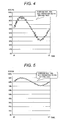
- FIG. 4 illustrates the case where an average SOC is 60% and a transition width is between 30% and 90%.
- Fig. 5 illustrates the case where an average SOC is 80% and a transition width is between 70% and 90%.
- the SOC of Fig. 5 makes a transition in a range higher than that of Fig. 4 (a range where sulfation of the negative electrode hardly occurs).
- FIG. 6 illustrates the case where an average SOC is 40% and a transition width is between 30% and 50%, and accordingly the SOC of Fig. 6 conversely makes a transition in a range lower than that of Fig. 4 (a range where sulfation of the negative electrode is likely to occur).
- Figs. 7 to 9 examples of the degradation model 107 of the lead acid storage batttery will be described with reference to Figs. 7 to 9 .
- the example of Fig. 7 represents the relationship between the center of an SOC transition and the equalized charge interval optimal for the center of an SOC transition, i.e., in which the life of the lead acid storage batttery can be made longest.
- the example of Fig. 8 represents the relationship between an SOC staying level and the equalized charge interval optimal for the SOC staying level, i.e., in which the life of the lead acid storage batttery can be made longest.
- an SOC staying level changes momentarily, it is also possible to determine an optimal equalized charge interval by, for example, weighing the SOC staying level in accordance with its staying period of time. It is also effective that an equalized charge interval is determined by "every certain days" as illustrated in Fig. 7 , or by "after certain Ah-charge/discharge (after certain Ah-discharge)" as illustrated in Fig. 8 .
- the example of Fig. 9 represents the relationship between an SOC staying level and an overcharge amount at equalized charge optimal for the SOC staying level.
- the life of the lead acid storage batttery can be extended by optimizing a timing of the equalized charge (equalized charge interval), a method of the equalized charge, and an overcharge amount, etc., in accordance with an SOC transition situation.
- a method of creating a degradation model is also described in detail in the aforementioned Japanese Patent Application No. 2009-225996 .
- the storage batttery state measurement unit 102 first measures a state (current, voltage, temperature, etc.) of the lead acid storage batttery 101 (S201).
- the SOC estimation unit 104 estimates a current SOC of the lead acid storage batttery by using the SOC model 103 representing the relationship between the current, voltage, and temperature of the lead acid storage batttery, and an SOC (S202). Then, the SOC transition history management unit 106 records an SOC transition of the lead acid storage batttery 101 in the SOC transition DB 105 (S203).
- the equalized charge optimal planning unit 108 inquiries for an SOC transition situation to the SOC transition history management unit 106, and the SOC transition history management unit 106 communicates an SOC transition situation to the equalized charge optimal planning unit 108 after referring to the SOC transition DB 105.
- the equalized charge optimal planning unit 108 determines, by using the degradation model 107 that is the information on operations of the lead acid storage batttery and degradation thereof, optimal operational conditions (equalized charge interval and equalized charge method) for the SOC transition history, in which the life of the lead acid storage batttery can be extended (S204).
- the SOC transition information-equalized charge information output unit 109 outputs the information on an SOC transition of the lead acid storage batttery, the information on the performance schedule thereof, and the information on the performance thereof (S205). That is, the SOC transition information-equalized charge information output unit 109 outputs outside the information on the SOC transition situation stored in the SOC transition DB 105 and the information on the performance schedule of the equalized charge determined by the equalized charge optimal planning unit 108.
- the equalized charge performance unit 110 performs equalized charge on the lead acid storage batttery in accordance with the method determined by the equalized charge optimal planning unit 108 (S206).
- an optimal equalized charge can be performed in accordance with a status of use (SOC transition situation) of the lead acid storage batttery, in which the life of the lead acid storage batttery can be extended.
- Figs. 11A and 11B illustrate output examples (displays) according to the first embodiment.
- An SOC transition situation and an equalized charge performance notice are displayed in the outputs.
- the portion with an SOC of 100% (or more) in the graph represents the time when the equalized charge is being performed.
- a timing of an equalized charge interval is changed in accordance with an SOC transition situation.
- the functional block according to the second embodiment is composed of a lead acid storage batttery 101, a storage batttery state measurement unit 102, an SOC model 301, an SOC estimation model selection unit 302, an SOC estimation unit 303, a temporary SOC estimation result DB 304, an SOC determination unit 305, an SOC model reliability DB 306, an SOC transition DB 105, an SOC transition history management unit 106, a degradation model 107, an equalized charge optimal planning unit 108, an SOC transition information-equalized charge information output unit 109, an equalized charge performance unit 110, and a learning unit 307.
- the SOC model 301 is a model representing the relationship between output factors of the lead acid storage batttery, such as current, voltage, and temperature, etc., and an SOC thereof.
- the SOC model 301 consists of: an SOC model at discharge 301a representing the relationship between output factors of the lead acid storage batttery at discharge, such as current, voltage, and temperature, etc., and an SOC thereof; and an SOC model at charge 301b representing the relationship between the current, voltage, and temperature, etc., of the lead acid storage batttery at charge, and an SOC thereof.
- the SOC model consisting of the SOC model at discharge 301a and the SOC model at charge 301b is created in advance by collecting the characteristic data of the lead acid storage batttery while discharge and charge are being performed such that the characteristics of the lead acid storage batttery are checked.
- a method of creating an SOC model is described, as an example, in detail in " MODELING METHOD FOR LEAD ACID STORAGE BATTTERY SIMULATION USING STEP CHANGING CURRENT” (Publication of Power and Energy Society B, Vol. 128 No. 8, 2008 ), which also includes a procedure of creating a model.
- the SOC estimation model selection unit 302 checks a current state of the lead acid storage batttery, either "at discharge” or "at charge”, by checking the current flowing in the lead acid storage batttery through the storage batttery state measurement unit 102. And then, the SOC estimation model selection unit 302 selects either of the SOC model at discharge 301a and the SOC model at charge 301b in accordance with the current state, the selected one being suitable for the estimation of an SOC.
- the SOC estimation unit 303 estimates an SOC of the lead acid storage batttery by using the selected one of the SOC model at discharge 301a and the SOC model at charge 301b and assumes the estimated SOC to be a temporary SOC.
- the determined temporary SOC estimation value is divided into an estimation result at discharge 304a and an estimation result at charge 304b to be stored in the temporary SOC estimation result DB 304.
- the SOC determination unit 305 determines a current SOC by weighing the temporary SOC estimation result at discharge and the temporary SOC estimation result at charge, which are stored in the temporary SOC estimation result DB 304, based on the information from the SOC model reliability DB 306.
- a final SOC can be determined by checking in advance the reliability of the SOC model in which, for example, the reliability of the SOC model at discharge 301a is almost the same as that of the SOC model at charge 301b in a region where an SOC is low while the reliability of the SOC model at discharge 301a is higher than that of "the model at charge” in a range where an SOC is high, and then by weighing the temporary SOC value in accordance with the reliability or the closeness from the time when estimation is desirably performed.
- a current SOC can be determined by weighing the temporary SOC estimation result (temporary SOC estimation value divided into “at discharge” and “at charge”) based on the information on the reliability and on how away it is from the time when the SOC is desirably to be determined).
- the determined SOC is stored in the SOC transition DB 105 followed by the determination of an equalized charge interval and a method thereof with a similar way. Alternatively, it may be made that the information in the SOC model reliability DB 306 is updated and learned, when needed, by providing the learning unit 307.
- an equalized charge interval and a method thereof can be determined based on the SOC model at discharge 301a, the SOC estimation model at charge 301b, and the "reliability", while an SOC is being estimated accurately.
- the storage batttery state measurement unit measures a state (current, voltage, temperature, etc.) of the lead acid storage batttery (S401). It is checked whether a state of the storage batttery is in a discharge state or a charge state (S402), and when in a discharge state, the SOC model selects the SOC model at discharge (S402a). When in a charge state, the SOC model selects the SOC model at charge (S402b).
- the SOC estimation unit estimates a current SOC of the lead acid storage batttery by using the selected SOC model and assumes the estimated current SOC to be a temporary SOC estimation value (S403).
- the temporary SOC estimation value is stored in the temporary SOC estimation result DB in accordance with a state of the storage batttery (discharge or charge) (S404).
- S404 discharge or charge
- S405 With reference to the SOC transition DB, the immediately before SOC state and charge/discharge state, and the reliability of the SOC model in the state are checked (S405).
- a current SOC (estimation result) is determined by using the nearest SOC estimation result and the temporary SOC estimation result in accordance with the state of the storage batttery and the reliability of the SOC model in the previous step (S406).
- the SOC transition history management unit records an SOC transition of the lead acid storage batttery in the SOC transition DB and evaluates the SOC transition situation (S407).
- the equalized charge optimal planning unit inquiries for the SOC transition situation to the SOC transition history management unit, and determines, for the SOC transition history, the optimal operational conditions (equalized charge interval and method thereof) in which the life of the lead acid storage batttery can be extended, by using the degradation model (S408).
- the SOC transition information-equalized charge information output unit outputs the information on the SOC transition of the lead acid storage batttery, the information on the performance schedule of the equalized charge, and the information on the performance thereof (S409).
- the equalized charge performance unit performs equalized charge on the lead acid storage batttery in accordance with the method determined by the equalized charge optimal planning unit (S410). With the aforementioned processing, optimal equalized charge can be performed in accordance with a status of use (SOC transition situation) of the lead acid storage batttery, in which the life of the lead acid storage batttery can be extended.
- SOC transition situation a status of use
- a method by which the life of the lead acid storage batttery can be extended will be described as a third embodiment of the present invention with reference to Figs. 14 and 15 , in which, when a predicted value of the wind power generation, as natural energy, can be obtained, a charge/discharge plan and a charge/discharge target by which the life of the lead acid storage batttery can be extended are set by using an SOC transition history and a degradation model.
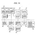
- Fig. 14 illustrates a functional block according to the third embodiment of the present invention.
- the functional block is composed of a lead acid storage batttery 101, a storage batttery state measurement unit 102, an SOC model 103, an SOC estimation unit 104, an SOC transition DB 105, an SOC transition history management unit 106, an wind power generation prediction DB 501, an wind power generation prediction unit 502, a degradation model 503, a charge/discharge planning unit 504, an wind power generation information-SOC transition information-charge/discharge information output unit 505, a charge/discharge performance unit 506, and a learning unit 507.
- the third embodiment is characterized by the fact that the charge/discharge planning unit 504 plans charge/discharge of the lead acid storage batttery by obtaining predicted values of the future wind power generation from the wind power generation prediction DB 501 and the wind power generation prediction unit 502 and by taking into consideration the situation of the lead acid storage batttery at the time, SOC transition situation thereof, and knowledge (degradation model 503) regarding operation and degradation thereof.
- the storage batttery state measurement unit first measures a state (current, voltage, temperature, etc.) of the lead acid storage batttery (S601). Subsequently, the SOC estimation unit estimates a current SOC of the lead acid storage batttery by using an SOC model representing the relationship between the current, voltage and temperature of the lead acid storage batttery, and an SOC (S602).
- the SOC transition history management unit records an SOC transition of the lead acid storage batttery in the SOC transition DB (S603).
- the wind power generation prediction unit predicts how a wind power generation amount makes a transition in the future by using the wind power generation prediction DB (S604).
- the charge/discharge planning unit plans optimal charge/discharge by using the SOC transition situation, the predicted result of the future transition of a wind power generation amount, and a degradation model representing the relationship between an operation (charge/discharge) of the lead acid storage batttery and the degradation thereof (S605).
- the SOC transition information-charge/discharge information-wind power generation information output unit outputs the predicted information on the wind power generation, the information on the SOC transition of the lead acid storage batttery, and the information on the charge/discharge thereof (S606).
- the charge/discharge performance unit performs charge/discharge of the lead acid storage batttery in accordance with the plan determined by the charge/discharge planning unit (S607).
- the learning unit updates the wind power generation prediction DB (predicted result and actual result of the wind power generation), the degradation model (relation between operation (charge/discharge) of the lead acid storage batttery and degradation thereof), and the SOC model (model representing the relationship between current, voltage, and temperature, and SOC) and learns from them (S608).
- a method by which the life of the lead acid storage batttery can be extended can be performed, in which, when a predicted value of the wind power generation, as natural energy, can be obtained, a charge/discharge plan and a charge/discharge target by which the life of the lead acid storage batttery can be extended are set by using an SOC transition history and a degradation model.
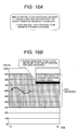
- Figs. 16A and 16B illustrate output examples of a charge/discharge plan.
- the charge/discharge planning unit 504 can make a plan in which a charge/discharge target value is set to be high within the SOC use range to prepare for large discharge. It can be expected that the life of the lead acid storage batttery can be further extended by planning an operation in which the life of the lead acid storage batttery can be extended while the future situation of the lead acid storage batttery is also being predicted, as stated above.
- Figs. 17A and 17B illustrate output examples (output of the wind power generation information-SOC transition information-charge/discharge information output unit 505) according to the present embodiment.
- the wind power generation is predicted such that "the windmill is to be cut out xx hours later fromnow due to strong wind”.
- the output of the windmill is decreased to zero from the "maximum”, and hence there are increased demands for discharge to the lead acid storage batttery.
- the sentence of "a charge/discharge target value will be set to be high (SOC 75%) within the SOC use range" is displayed.
- People who operate the lead acid storage batttery can utilize the lead acid storage batttery systematically by outputting a predicted result of the wind power generation and a charge/discharge target, etc., in this way. It also becomes possible for users controlling the lead acid storage batttery to easily operate and control the lead acid storage batttery by a notice of a timing when the equalized charge is performed.
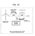
- Fig. 18 illustrates the system configuration when the present invention is applied to a wind power generation system.
- a power generation output of the wind power generation is equalized by the power storage system output of the lead acid storage batttery or lead acid storage batttery system and supplied to the system as an stabilized system output.
- the life of the lead acid storage batttery or lead acid storage batttery system according to the present invention can be extended by being operated at proper frequencies based on the information on an SOC transition, thereby greatly contributing to an efficient operation of the whole natural energy system.
Landscapes
- Engineering & Computer Science (AREA)
- Power Engineering (AREA)
- General Chemical & Material Sciences (AREA)
- Chemical & Material Sciences (AREA)
- Chemical Kinetics & Catalysis (AREA)
- Electrochemistry (AREA)
- Manufacturing & Machinery (AREA)
- Physics & Mathematics (AREA)
- General Physics & Mathematics (AREA)
- Microelectronics & Electronic Packaging (AREA)
- Secondary Cells (AREA)
- Charge And Discharge Circuits For Batteries Or The Like (AREA)
- Tests Of Electric Status Of Batteries (AREA)
Description
- The present invention relates to a lead acid storage batttery and a lead acid storage batttery system that are used in a natural energy utilization system, such as a wind power generation system, and in particular, to a lead acid storage batttery and a lead acid storage batttery system that are used in a natural energy utilization system in which the life of the lead acid storage batttery can be extended and the cost of equalized charge and the loss involving stops of a wind power generation storage system can be reduced by grasping the SOC (State of Charge) transition of the lead acid storage batttery used for suppressing the fluctuation in the windpower generation such that the equalized charge of the lead acid storage batttery is performed at a proper frequency and in a proper method in accordance with the SOC transition situation.
- Global warming is a serious problem for all humankind, and in order to delay and stop the progress of the warming, every country is trying to promote energy saving by building efficient power systems or smart grids, and promote large-scale introduction of natural energies that do not discharge carbon dioxide, such as photovoltaic power generation and wind power generation, etc.
- For example, the wind power generation has the merit of not discharging carbon dioxide by utilizing natural energy that circulates in the atmosphere; however, there is the concern that the power system may be adversely affected or the quality of power may be deteriorated because the output of the power generation is dependent on wind conditions and accordingly unstable. In order to prevent such an adverse influence on the power system and utilize the energy effectively, it is expected that a wind power generation storage system is achieved in which energy fluctuations are equalized such that the output of the power generation is stabilized by using a lead acid storage batttery, etc. The lead acid storage batttery used for suppressing the fluctuation in the output of the wind power generation is required to have the same long life as a wind power generator and be installed at a low cost.
- The lead acid storage batttery for suppressing the fluctuation in the output of the wind power generation is operated in a PSOC (Partial State of Charge) such that charge/discharge can be performed in accordance with the fluctuation in the output of the wind power generation. Accordingly, the lead acid storage batttery is not fully charged in a normal operation state, different from the conventional lead acid storage batttery for emergency that is fully charged normally and discharged when needed and industrial lead acid storage batttery that is fully charged at night and discharged when a load is large in the daytime. In order to prevent the degradation of the negative electrode due to sulfation occurring in a low SOC in the particular application, equalized charge (recovery charge) is regularly (usually once every one or two weeks) performed in which the lead acid storage batttery is fully charged. Another purpose of the equalized charge is, for accurately grasping an SOC, to regularly reset an SOC value such that the value is made to be 100% after the equalized charge.
- However, there has been a problem that, if the equalized charge is performed too often, degradation of the positive electrode conversely occurs due to the overcharge, and thereby the life of the lead acid storage batttery is shortened, etc.
Patent document 1 discloses the case where equalized charge intervals of a lead acid storage batttery are changed in accordance with ambient temperature. Patent document 2 discloses that the degradation of the positive electrode is prevented by setting the amount of the overcharge at the equalized charge of a lead acid storage battery to a lower value (99% to 102%) than the conventional one (110% to 115%).
Thedocument EP 1 160 953 A2 teaches to calculate the SOC from the Open Circuit Voltage (OCV) and to trigger a refresh charge when the battery is not used and when SOC falls short of a threshold value or when a predetermined time has elapsed -
- [Patent document 1] Japanese Unexamined Patent Publication No.
2003-288947 - [Patent document 2] Japanese Unexamined Patent Publication No.
2004-39434 - An object of the present invention is to provide, in lead acid batteries or lead acid storage battery systems that are used in natural energy utilization systems, a new lead acid storage battery and a new lead acid storage battery system in which the life of the lead acid storage battery can be extended by changing an equalized charge interval performed on the lead acid storage battery in accordance with a status of use (SOC transition) of the lead acid storage battery, and the lead acid storage battery is also made to be advantageous in terms of cost by reducing the equalized charge only for grasping an SOC to reduce the power and cost for equalized charge, and by reducing the number of stops of a natural energy storage system.
- Another object of the present invention is to provide a lead acid storage batttery and a lead acid storage batttery system whose operations can be easily managed by making a timing when the next equalized charge is scheduled to be performed understandable for those who operate the lead acid storage batttery.
- The present invention relates to a lead acid storage batttery or lead acid storage batttery system to be used in a natural energy utilization system, including: a storage batttery state measurement unit for measuring a state of the lead acid storage batttery; an SOC model representing the relationship between output factors of the lead acid storage batttery including current, voltage, and temperature thereof, and a state of charge of the lead acid storage batttery; and an equalized charge performance unit for performing equalized charge of the lead acid storage batttery. The lead acid storage batttery or lead acid storage batttery system comprises: an SOC estimation unit configured to estimate a state of charge of the lead acid storage batttery from the information measured by the storage batttery state measurement unit and the information from the SOC model; an SOC transition DB configure to record how a state of charge of the lead acid storage batttery makes a transition; an SOC transition history management unit configured to record, in the SOC transition DB, a value of state of charge estimated by the SOC estimation unit and to check an SOC transition situation; a degradation model representing the relationship between an operation situation of the lead acid storage batttery including a state of charge of the lead acid storage batttery and degradation; and an equalized charge optimal planning unit configured to plan an optimal method of performing the equalized charge based on the information on the SOC transition situation from the SOC transition history management unit and the information from the degradation model.
- Also, in the lead acid storage batttery or lead acid storage batttery system to be used in a natural energy utilization system, the equalized charge optimal planning unit further has an equalized charge interval determination unit and an equalized charge method determination unit.
- Also, in the lead acid storage batttery or lead acid storage batttery system to be used in a natural energy utilization system, the SOC model has an SOC model at discharge, an SOC model at charge, and an SOC estimation model selection unit configured to select one of the SOC model at discharge and the SOC model at charge based on the information from the storage batttery state measurement unit.
- Also, the lead acid storage batttery or lead acid storage batttery system to be used in a natural energy utilization system further has a temporary SOC estimation result DB and an SOC model reliability DB, and the SOC estimation unit estimates a temporary SOC, which is an SOC of the lead acid storage batttery, by using the selected one of the SOC model at discharge and the SOC model at charge, and divides the estimated temporary SOC into an estimation result at discharge and an estimation result at charge to store in the temporary SOC estimation result DB, and the SOC estimation unit estimates a current SOC based on the estimation result at discharge, the estimation result at charge, and the information from the SOC model reliability DB.
- Also, in the lead acid storage batttery or lead acid storage batttery system to be used in a natural energy utilization system, an "equalized charge interval" determined by the equalized charge optimal planning unit is based on any one of a discharge amount (Ah), a charge/discharge amount (Ah), a discharge period of time, and discharge days of the lead acid storage batttery. Also, the lead acid storage batttery or lead acid storage batttery system to be used in a natural energy utilization system further comprise an SOC transition information-equalized charge information output unit configured to output outside the information on the SOC transition situation stored in the SOC transition DB and the information on a performance schedule of the equalized charge determined by the equalized charge optimal planning unit.
- Also, the lead acid storage batttery or lead acid storage batttery system to be used in a natural energy utilization system includes an SOC transition information-equalized charge information output unit configured to output outside the information on an SOC transition situation stored in the SOC transition DB and the information on a performance schedule of the equalized charge determined by the equalized charge optimal planning unit.
- Also, in the lead acid storage batttery or lead acid storage batttery system to be used in a natural energy utilization system, the SOC transition information-equalized charge information output unit outputs the information on a discharge amount (Ah) or a charge/discharge amount (Ah) of the lead acid storage batttery, besides the information on the SOC transition situation and the information on the performance schedule of the equalized charge.
- A lead acid storage batttery or lead acid storage batttery system to be used in a natural energy utilization system, including: a storage batttery state measurement unit for measuring a state of the lead acid storage batttery; an SOC model representing the relationship between output factors including current, voltage, and temperature of the lead acid storage batttery and a state of charge of the lead acid storage batttery; and a charge/discharge performance unit for performing equalized charge of the lead acid storage batttery, includes: an SOC estimation unit configured to estimate a state of charge of the lead acid storage batttery from the information measured by the storage batttery state measurement unit and the information from the SOC model; an SOC transition DB configured to record an SOC transition situation of the lead acid storage batttery; an SOC transition history management unit configured to record, in the SOC transition DB, a value of SOC estimated by the SOC estimation unit and to check an SOC transition situation; a wind power generation prediction DB created by analyzing the wind power generation information in the past to obtain a predictive value of the wind power generation; a wind power generation prediction unit configured to predict a wind power generation amount in the future by using the wind power generation prediction DB; a degradation model representing the relationship between an operation situation of the lead acid storage batttery including an SOC thereof and charge/discharge of the storage batttery, and degradation; a charge/discharge planning unit configured to plan charge/discharge of the lead acid storage batttery optimal for the extension of the life of the lead acid storage batttery, based on the information on the prediction result of the wind power generation in the future from the wind power generation prediction unit, the information on the SOC estimation situation from the SOC transition history management unit, and the information from the degradation model; and a charge/discharge performance unit configured to control charge/discharge of lead acid storage batttery in accordance with the charge/discharge plan determined by the charge/discharge planning unit.
- Also, the lead acid storage batttery or lead acid storage batttery system to be used in a natural energy utilization system includes a wind power generation information-SOC transition information-charge/discharge information output unit configured to output outside the information on the prediction result of the wind power generation by the wind power generation prediction unit, the information on the SOC transition situation stored in the SOC transition DB, and the information on the charge/discharge determined by the charge/discharge planning unit.
- According to the present invention, in a lead acid storage batttery or lead acid storage batttery system to be used in a natural energy utilization system, the life of the lead acid storage batttery can be extended by optimizing the frequency at which the equalized charge is performed and the charge method in terms of the SOC transition situation, life, and degradation, with: an SOC estimation unit configured to estimate a state of charge from the information from a storage batttery state measurement unit and the information from an SOC model; an SOC transition DB configured to record a state of charge transition of the lead acid storage batttery; an SOC transition history management unit configured to record, in the SOC transition DB, an estimated value of state of charge and to check an SOC transition situation; a degradation model; and an equalized charge optimal planning unit configured to plan an optimal method of performing the equalized charge based on the information on the SOC transition situation from the SOC transition history management unit and the information from the degradation model, being provided.
-
-
Fig. 1 is a functional block diagram of a first embodiment according to the present invention. -
Fig. 2 is a graph illustrating SOC estimation using an SOC model according to the first embodiment of the invention. -
Fig. 3 is a graph illustrating the SOC model (discharge characteristics model) according to the first embodiment of the invention. -
Fig. 4 is a graph illustrating the data in an SOC transition DB according to the first embodiment of the invention. -
Fig. 5 is a graph illustrating the data in the SOC transition DB. -
Fig. 6 is a graph illustrating the data in the SOC transition DB. -
Fig. 7 is a graph illustrating a degradation model. -
Fig. 8 is a graph illustrating a degradation model according to the first embodiment of the invention. -
Fig. 9 is a graph illustrating a degradation model. -
Fig. 10 is a processing flow diagram according to the first embodiment of the invention. -
Fig. 11A is an illustrative diagram of an output of an SOC transition situation and an equalized charge notice according to the first embodiment of the invention. -
Fig. 11B is an illustrative diagram of an output of the SOC transition situation and the equalized charge notice according to the first embodiment of the invention. -
Fig. 12 is a functional block diagram of a second embodiment of the invention. -
Fig. 13 is a processing flow diagram according to the second embodiment of the invention. -
Fig. 14 is a functional block diagram according to a third embodiment. -
Fig. 15 is a processing flow diagram according to the third embodiment of the invention. -
Fig. 16A is an illustrative diagram of target setting of charge/discharge according to the third embodiment of the invention. -
Fig. 16B is an illustrative diagram of target setting of the charge/discharge according to the third embodiment of the invention. -
Fig. 17A is an illustrative diagram of an output of an SOC transition situation and an equalized charge notice according to the third embodiment of the invention. -
Fig. 17B is an illustrative diagram of an output of the SOC transition situation and the equalized charge notice according to the third embodiment of the invention. -
Fig. 18 is a schematic diagram illustrating a lead acid storage batttery system for wind power generation to which the invention is applied. - Hereinafter, preferred embodiments of the present invention will be described in detail with reference to the accompanying drawings.
-
Fig. 1 illustrates a functional block diagram of a lead acid storage batttery and a lead acid storage batttery system according to a first embodiment of the present invention, which are to be applied to a natural energy utilization system. The lead acid storage batttery system of the invention is composed of a leadacid storage batttery 101, a storage battterystate measurement unit 102, anSOC model 103, anSOC estimation unit 104, anSOC transition DB 105, an SOCtransition history managementunit 106, adegradation model 107, an equalized chargeoptimal planning unit 108, an SOC transition information-equalized chargeinformation output unit 109, and an equalizedcharge control unit 110. - The function of each of the aforementioned components will be described. The storage batttery
state measurement unit 102 has acurrent measurement unit 102a, avoltage measurement unit 102b, and atemperature measurement unit 102c such that a state of the lead acid storage batttery, such as current (A), voltage (V), and temperature (°C), etc. , of the leadacid storage batttery 101, is measured. - The
SOC model 103 is a model representing the relationship between current, voltage, and temperature, etc., of the lead acid storage batttery, and a storage batttery SOC thereof, and is created in advance by checking the characteristics of the lead acid storage batttery. - A method of creating an SOC model is described, as an example, in detail in "MODELING METHOD FOR LEAD ACID STORAGE BATTTERY SIMULATION USING STEP CHANGING CURRENT" (Publication of Power and Energy Society B, Vol. 128 No. 8, 2008), which also includes a procedure of creating a model.
- The
SOC estimation unit 104 estimates an SOC of the lead acid storage batttery from the information measured by the storage battterystate measurement unit 102 and the information from theSOC model 103.Fig. 2 illustrates an example in which an SOC is estimated by using the SOC model (discharge model) representing the relationship between current, voltage, and temperature of the lead acid storage batttery and a storage batttery SOC thereof. - A method of estimating an SOC of a lead acid storage batttery using an SOC model is described in detail in Japanese PatentApplicationNo.
2009-225996 - The
SOC transition DB 105 is a database for recording how an SOC of the lead acid storage batttery makes a transition. TheSOC estimation unit 104 records and adds the information on an SOC estimation result in theSOC transition DB 105. An SOC estimation result is recorded or updated when needed in a method, or SOC estimation results are recorded every certain period of time in another method. - The SOC transition
history management unit 106 records, in theSOC transition DB 105, the SOC value estimated by theSOC estimation unit 104 and extracts the information on the SOC transition situation in the past from theSOC transition DB 105. For example, the SOC transitionhistory management unit 106 extracts and provides the data on the SOC transition situation for an immediately preceding certain period of time, according to the demand of the equalized chargeoptimal planning unit 108. - The
degradation model 107 includes the relationship between an operation situation of the storage batttery including an SOC thereof and degradation, and the information indicating an SOC and an optimal interval and method, etc. , of the equalized charge corresponding to the SOC. Thedegradation model 107 is created in advance by checking the relationship between an operation of the lead acid storage batttery and the life and degradation thereof. - A method of creating a model representing the relationship between an operation situation of a storage batttery including an SOC of a lead acid storage batttery and degradation is described in detail in Japanese Patent Application No.
2009-001345 - The equalized charge
optimal planning unit 108 has an equalized chargeinterval determination unit 108a and an equalized chargemethod determination unit 108b that are configured to acquire an SOC transition situation from the SOC transitionhistory management unit 106 and determine an optimal equalized charge interval and method of the lead acid storage batttery in accordance with each SOC transition situation such that the degradation is prevented and the life of the lead acid storage batttery is extended. With the aforementioned configuration, the equalized chargeoptimal planning unit 108 determines an optimal method of performing the equalized charge, in which the predicted life of the lead acid storage batttery is made longest, by using the information from thedegradation model 107. - The SOC transition information-equalized charge
information output unit 109 outputs outside the information on the SOC transition situation stored in theSOC transition DB 105 and the information on the performance schedule of the equalized charge determined by the equalized chargeoptimal planning unit 108. - The equalized
charge control unit 110 performs the equalized charge (recovery charge) on the leadacid storage batttery 101 in accordance with the plan determined by the equalized chargeoptimal planning unit 108. - Subsequently, an SOC model and estimation of an SOC using the SOC model will be described with reference to
Figs. 2 and 3. Figs. 2 and 3 illustrate examples of an SOC model (discharge model) representing the relationship between current, voltage, and temperature of the lead acid storage batttery, and a storage batttery SOC thereof. - The curve in
Fig. 2 illustrates an example (temperature: 25°C, discharge current: 8 A) of an SOC model representing the relationship between the current, voltage, and temperature of the lead acid storage batttery and a storage batttery SOC thereof. In the graph, the vertical axis represents a terminal voltage (V) and the horizontal axis represents an SOC. Accordingly, it is assumed that, when temperature is, for example, 25°C, current of 8 A is made to flow and a terminal voltage at the time is 2.04 (V). In this case, it can be estimated that an SOC of the lead acid storage batttery is 0.85 (85%) from the SOC model, as illustrated inFig. 7 . -
Fig. 2 illustrates only one example where temperature is 25°C and discharge current is 8 A; however, even if it is limited to a model where temperature is, for example, 25°C, there exist multiple characteristic curves for every current, as illustrated inFig. 3 . Further, there exists a model having such multiple curves for every temperature characteristic and degradation (it is desirable that characteristic curves are further prepared for every temperature characteristic and every degradation). - An SOC model and a method of estimating an SOC using the SOC model (
Figs. 2 and 3 ) are described in detail in the previously described Japanese Patent Application2009-225996 - Subsequently, examples of an SOC transition situation stored in the SOC transition DB will be described with reference to
Figs. 4 to 6 . The examples of the diagrams illustrate an SOC transition at each time, and an average SOC and a transition width for a certain period of time, etc.Fig. 4 illustrates the case where an average SOC is 60% and a transition width is between 30% and 90%.Fig. 5 illustrates the case where an average SOC is 80% and a transition width is between 70% and 90%. The SOC ofFig. 5 makes a transition in a range higher than that ofFig. 4 (a range where sulfation of the negative electrode hardly occurs).Fig. 6 illustrates the case where an average SOC is 40% and a transition width is between 30% and 50%, and accordingly the SOC ofFig. 6 conversely makes a transition in a range lower than that ofFig. 4 (a range where sulfation of the negative electrode is likely to occur). - Subsequently, examples of the
degradation model 107 of the lead acid storage batttery will be described with reference toFigs. 7 to 9 . The example ofFig. 7 represents the relationship between the center of an SOC transition and the equalized charge interval optimal for the center of an SOC transition, i.e., in which the life of the lead acid storage batttery can be made longest. The example ofFig. 8 represents the relationship between an SOC staying level and the equalized charge interval optimal for the SOC staying level, i.e., in which the life of the lead acid storage batttery can be made longest. Although an SOC staying level changes momentarily, it is also possible to determine an optimal equalized charge interval by, for example, weighing the SOC staying level in accordance with its staying period of time. It is also effective that an equalized charge interval is determined by "every certain days" as illustrated inFig. 7 , or by "after certain Ah-charge/discharge (after certain Ah-discharge)" as illustrated inFig. 8 . The example ofFig. 9 represents the relationship between an SOC staying level and an overcharge amount at equalized charge optimal for the SOC staying level. - Thus, the life of the lead acid storage batttery can be extended by optimizing a timing of the equalized charge (equalized charge interval), a method of the equalized charge, and an overcharge amount, etc., in accordance with an SOC transition situation. A method of creating a degradation model is also described in detail in the aforementioned Japanese Patent Application No.
2009-225996 - Subsequently, the processing flow according to the first embodiment will be described for each step with reference to
Fig. 10 . The storage battterystate measurement unit 102 first measures a state (current, voltage, temperature, etc.) of the lead acid storage batttery 101 (S201). - Subsequently, the
SOC estimation unit 104 estimates a current SOC of the lead acid storage batttery by using theSOC model 103 representing the relationship between the current, voltage, and temperature of the lead acid storage batttery, and an SOC (S202). Then, the SOC transitionhistory management unit 106 records an SOC transition of the leadacid storage batttery 101 in the SOC transition DB 105 (S203). - The equalized charge
optimal planning unit 108 inquiries for an SOC transition situation to the SOC transitionhistory management unit 106, and the SOC transitionhistory management unit 106 communicates an SOC transition situation to the equalized chargeoptimal planning unit 108 after referring to theSOC transition DB 105. The equalized chargeoptimal planning unit 108 determines, by using thedegradation model 107 that is the information on operations of the lead acid storage batttery and degradation thereof, optimal operational conditions (equalized charge interval and equalized charge method) for the SOC transition history, in which the life of the lead acid storage batttery can be extended (S204). - The SOC transition information-equalized charge
information output unit 109 outputs the information on an SOC transition of the lead acid storage batttery, the information on the performance schedule thereof, and the information on the performance thereof (S205). That is, the SOC transition information-equalized chargeinformation output unit 109 outputs outside the information on the SOC transition situation stored in theSOC transition DB 105 and the information on the performance schedule of the equalized charge determined by the equalized chargeoptimal planning unit 108. - The equalized
charge performance unit 110 performs equalized charge on the lead acid storage batttery in accordance with the method determined by the equalized charge optimal planning unit 108 (S206). - With the aforementioned processing, an optimal equalized charge can be performed in accordance with a status of use (SOC transition situation) of the lead acid storage batttery, in which the life of the lead acid storage batttery can be extended.
-
Figs. 11A and 11B illustrate output examples (displays) according to the first embodiment. An SOC transition situation and an equalized charge performance notice are displayed in the outputs. The portion with an SOC of 100% (or more) in the graph represents the time when the equalized charge is being performed. To achieve the extension of the life of the lead acid storage batttery, a timing of an equalized charge interval is changed in accordance with an SOC transition situation. As illustrated inFigs. 11A and 11B , however, it becomes easy for users of the lead acid storage batttery to operate and control the lead acid storage batttery with an equalized charge performance timing, which can be predicted from the up-to-now SOC transition situations, being notified. - Subsequently, in a second embodiment of the present invention, a detailed functional block diagram, which is expected to be more accurate, will be illustrated in
Fig. 12 . The functional block according to the second embodiment is composed of a leadacid storage batttery 101, a storage battterystate measurement unit 102, anSOC model 301, an SOC estimationmodel selection unit 302, anSOC estimation unit 303, a temporary SOCestimation result DB 304, anSOC determination unit 305, an SOCmodel reliability DB 306, anSOC transition DB 105, an SOC transitionhistory management unit 106, adegradation model 107, an equalized chargeoptimal planning unit 108, an SOC transition information-equalized chargeinformation output unit 109, an equalizedcharge performance unit 110, and alearning unit 307. - Of every function according to the second embodiment, the portions different from those in
Fig. 1 will only be described. TheSOC model 301 is a model representing the relationship between output factors of the lead acid storage batttery, such as current, voltage, and temperature, etc., and an SOC thereof. TheSOC model 301 consists of: an SOC model atdischarge 301a representing the relationship between output factors of the lead acid storage batttery at discharge, such as current, voltage, and temperature, etc., and an SOC thereof; and an SOC model atcharge 301b representing the relationship between the current, voltage, and temperature, etc., of the lead acid storage batttery at charge, and an SOC thereof. Herein, the SOC model consisting of the SOC model atdischarge 301a and the SOC model atcharge 301b is created in advance by collecting the characteristic data of the lead acid storage batttery while discharge and charge are being performed such that the characteristics of the lead acid storage batttery are checked. - A method of creating an SOC model is described, as an example, in detail in "MODELING METHOD FOR LEAD ACID STORAGE BATTTERY SIMULATION USING STEP CHANGING CURRENT" (Publication of Power and Energy Society B, Vol. 128 No. 8, 2008), which also includes a procedure of creating a model.
- The SOC estimation
model selection unit 302 checks a current state of the lead acid storage batttery, either "at discharge" or "at charge", by checking the current flowing in the lead acid storage batttery through the storage battterystate measurement unit 102. And then, the SOC estimationmodel selection unit 302 selects either of the SOC model atdischarge 301a and the SOC model atcharge 301b in accordance with the current state, the selected one being suitable for the estimation of an SOC. - The
SOC estimation unit 303 estimates an SOC of the lead acid storage batttery by using the selected one of the SOC model atdischarge 301a and the SOC model atcharge 301b and assumes the estimated SOC to be a temporary SOC. The determined temporary SOC estimation value is divided into an estimation result atdischarge 304a and an estimation result atcharge 304b to be stored in the temporary SOCestimation result DB 304. - The
SOC determination unit 305 determines a current SOC by weighing the temporary SOC estimation result at discharge and the temporary SOC estimation result at charge, which are stored in the temporary SOCestimation result DB 304, based on the information from the SOCmodel reliability DB 306. - A final SOC can be determined by checking in advance the reliability of the SOC model in which, for example, the reliability of the SOC model at
discharge 301a is almost the same as that of the SOC model atcharge 301b in a region where an SOC is low while the reliability of the SOC model atdischarge 301a is higher than that of "the model at charge" in a range where an SOC is high, and then by weighing the temporary SOC value in accordance with the reliability or the closeness from the time when estimation is desirably performed. - For example, in the case where the lead acid storage batttery is currently being in "a range where an SOC is high" and currently being "charged"; however, the lead acid storage batttery was "discharged" just before and there remains the temporary SOC value at the time, a current SOC can be determined by weighing the temporary SOC estimation result (temporary SOC estimation value divided into "at discharge" and "at charge") based on the information on the reliability and on how away it is from the time when the SOC is desirably to be determined).
- The determined SOC is stored in the
SOC transition DB 105 followed by the determination of an equalized charge interval and a method thereof with a similar way. Alternatively, it may be made that the information in the SOCmodel reliability DB 306 is updated and learned, when needed, by providing thelearning unit 307. - With the aforementioned configuration, an equalized charge interval and a method thereof can be determined based on the SOC model at
discharge 301a, the SOC estimation model atcharge 301b, and the "reliability", while an SOC is being estimated accurately. - Subsequently, the processing flow according to the second embodiment will be described briefly with reference to
Fig. 13 . The storage batttery state measurement unit measures a state (current, voltage, temperature, etc.) of the lead acid storage batttery (S401). It is checked whether a state of the storage batttery is in a discharge state or a charge state (S402), and when in a discharge state, the SOC model selects the SOC model at discharge (S402a). When in a charge state, the SOC model selects the SOC model at charge (S402b). The SOC estimation unit estimates a current SOC of the lead acid storage batttery by using the selected SOC model and assumes the estimated current SOC to be a temporary SOC estimation value (S403). The temporary SOC estimation value is stored in the temporary SOC estimation result DB in accordance with a state of the storage batttery (discharge or charge) (S404). With reference to the SOC transition DB, the immediately before SOC state and charge/discharge state, and the reliability of the SOC model in the state are checked (S405). A current SOC (estimation result) is determined by using the nearest SOC estimation result and the temporary SOC estimation result in accordance with the state of the storage batttery and the reliability of the SOC model in the previous step (S406). - The SOC transition history management unit records an SOC transition of the lead acid storage batttery in the SOC transition DB and evaluates the SOC transition situation (S407). The equalized charge optimal planning unit inquiries for the SOC transition situation to the SOC transition history management unit, and determines, for the SOC transition history, the optimal operational conditions (equalized charge interval and method thereof) in which the life of the lead acid storage batttery can be extended, by using the degradation model (S408). The SOC transition information-equalized charge information output unit outputs the information on the SOC transition of the lead acid storage batttery, the information on the performance schedule of the equalized charge, and the information on the performance thereof (S409). The equalized charge performance unit performs equalized charge on the lead acid storage batttery in accordance with the method determined by the equalized charge optimal planning unit (S410). With the aforementioned processing, optimal equalized charge can be performed in accordance with a status of use (SOC transition situation) of the lead acid storage batttery, in which the life of the lead acid storage batttery can be extended.
- Subsequently, a method by which the life of the lead acid storage batttery can be extended will be described as a third embodiment of the present invention with reference to
Figs. 14 and15 , in which, when a predicted value of the wind power generation, as natural energy, can be obtained, a charge/discharge plan and a charge/discharge target by which the life of the lead acid storage batttery can be extended are set by using an SOC transition history and a degradation model. -
Fig. 14 illustrates a functional block according to the third embodiment of the present invention. The functional block is composed of a leadacid storage batttery 101, a storage battterystate measurement unit 102, anSOC model 103, anSOC estimation unit 104, anSOC transition DB 105, an SOC transitionhistory management unit 106, an wind powergeneration prediction DB 501, an wind powergeneration prediction unit 502, adegradation model 503, a charge/discharge planning unit 504, an wind power generation information-SOC transition information-charge/dischargeinformation output unit 505, a charge/discharge performance unit 506, and alearning unit 507. - The third embodiment is characterized by the fact that the charge/
discharge planning unit 504 plans charge/discharge of the lead acid storage batttery by obtaining predicted values of the future wind power generation from the wind powergeneration prediction DB 501 and the wind powergeneration prediction unit 502 and by taking into consideration the situation of the lead acid storage batttery at the time, SOC transition situation thereof, and knowledge (degradation model 503) regarding operation and degradation thereof. - Subsequently, the processing flow will be described with reference to
Fig. 15 . The storage batttery state measurement unit first measures a state (current, voltage, temperature, etc.) of the lead acid storage batttery (S601). Subsequently, the SOC estimation unit estimates a current SOC of the lead acid storage batttery by using an SOC model representing the relationship between the current, voltage and temperature of the lead acid storage batttery, and an SOC (S602). - Then, the SOC transition history management unit records an SOC transition of the lead acid storage batttery in the SOC transition DB (S603).
- The wind power generation prediction unit predicts how a wind power generation amount makes a transition in the future by using the wind power generation prediction DB (S604).
- The charge/discharge planning unit plans optimal charge/discharge by using the SOC transition situation, the predicted result of the future transition of a wind power generation amount, and a degradation model representing the relationship between an operation (charge/discharge) of the lead acid storage batttery and the degradation thereof (S605).
- The SOC transition information-charge/discharge information-wind power generation information output unit outputs the predicted information on the wind power generation, the information on the SOC transition of the lead acid storage batttery, and the information on the charge/discharge thereof (S606). The charge/discharge performance unit performs charge/discharge of the lead acid storage batttery in accordance with the plan determined by the charge/discharge planning unit (S607).
- In addition, the learning unit updates the wind power generation prediction DB (predicted result and actual result of the wind power generation), the degradation model (relation between operation (charge/discharge) of the lead acid storage batttery and degradation thereof), and the SOC model (model representing the relationship between current, voltage, and temperature, and SOC) and learns from them (S608).
- With the aforementioned processing, a method by which the life of the lead acid storage batttery can be extended can be performed, in which, when a predicted value of the wind power generation, as natural energy, can be obtained, a charge/discharge plan and a charge/discharge target by which the life of the lead acid storage batttery can be extended are set by using an SOC transition history and a degradation model.
-
Figs. 16A and 16B illustrate output examples of a charge/discharge plan. For example, it is assumed that the wind is expected to be drastically weakened xx hours later from now such that the output thereof is drastically decreased, and in order to cover that, the lead acid storage batttery is expected to be demanded for much discharge. Then, the charge/discharge planning unit 504 can make a plan in which a charge/discharge target value is set to be high within the SOC use range to prepare for large discharge. It can be expected that the life of the lead acid storage batttery can be further extended by planning an operation in which the life of the lead acid storage batttery can be extended while the future situation of the lead acid storage batttery is also being predicted, as stated above. -
Figs. 17A and 17B illustrate output examples (output of the wind power generation information-SOC transition information-charge/discharge information output unit 505) according to the present embodiment. Bedsides an SOC transition situation (graph), the predicted information on the wind power generation, a charge/discharge target value, and a performance schedule of the equalized charge, etc., are displayed on the output screen. In this example, the wind power generation is predicted such that "the windmill is to be cut out xx hours later fromnow due to strong wind". When the windmill is cut out, the output of the windmill is decreased to zero from the "maximum", and hence there are increased demands for discharge to the lead acid storage batttery. Accordingly, in this example, the sentence of "a charge/discharge target value will be set to be high (SOC 75%) within the SOC use range" is displayed. People who operate the lead acid storage batttery can utilize the lead acid storage batttery systematically by outputting a predicted result of the wind power generation and a charge/discharge target, etc., in this way. It also becomes possible for users controlling the lead acid storage batttery to easily operate and control the lead acid storage batttery by a notice of a timing when the equalized charge is performed. -
Fig. 18 illustrates the system configuration when the present invention is applied to a wind power generation system. InFig. 18 , a power generation output of the wind power generation is equalized by the power storage system output of the lead acid storage batttery or lead acid storage batttery system and supplied to the system as an stabilized system output. In the wind power generation system, the life of the lead acid storage batttery or lead acid storage batttery system according to the present invention can be extended by being operated at proper frequencies based on the information on an SOC transition, thereby greatly contributing to an efficient operation of the whole natural energy system. -
- 101
- LEAD ACID STORAGE BATTTERY
- 102
- STORAGE BATTTERY STATE MEASUREMENT UNIT
- 103
- SOC MODEL
- 110
- EQUALIZED CHARGE PERFORMANCE UNIT
- 104
- SOC ESTIMATION UNIT
- 105
- SOC TRANSITION DB
- 106
- SOC TRANSITION HISTORY MANAGEMENT UNIT
- 107
- DEGRADATION MODEL
- 108
- EQUALIZED CHARGE OPTIMAL PLANNING UNIT
- 108a
- EQUALIZED CHARGE INTERVAL DETERMINATION UNIT
- 108b
- EQUALIZED CHARGE METHOD DETERMINATION UNIT
- 109
- SOC TRANSITION INFORMATION-EQUALIZED CHARGE INFORMATION OUTPUT UNIT
- 301a
- SOC MODEL AT DISCHARGE
- 301b
- SOC MODEL AT CHARGE
- 302
- SOC ESTIMATION MODEL SELECTION UNIT
- 304
- TEMPORARY SOC ESTIMATION RESULT DB
- 306
- SOC MODEL RELIABILITY DB
- 506
- CHARGE/DISCHARGE PERFORMANCE UNIT
- 501
- WIND POWER GENERATION PREDICTION DB
- 502
- WIND POWER GENERATION PREDICTION UNIT
- 504
- CHARGE/DISCHARGE PLANNING UNIT
- 505
- WIND POWER GENERATION INFORMATION-SOC TRANSITION INFORMATION-CHARGE/DISCHARGE INFORMATION OUTPUT UNIT
Claims (12)
- A lead acid storage battery system for use in a natural energy utilization system, including: a lead acid storage battery (101); a storage battery state measurement unit (102) for measuring a state of the lead acid storage battery (101); an SOC model (103) representing the relationship between factors of the lead acid storage battery (101), such as current, voltage, and temperature, and a storage battery charge of state of the lead acid storage battery (101); and an equalized charge performance unit (110) for performing equalized charge of the lead acid storage battery (101), wherein said equalized charge includes fully charging the lead acid storage battery (101), the lead acid storage battery system comprising:an SOC estimation unit (104) configured to estimate a state of charge of the lead acid storage battery (101) from the information measured by the storage battery state measurement unit (102) and the information from the SOC model (103);characterized in that the lead acid storage battery system further comprises:an SOC transition DataBase (105) configured to record how a state of charge of the lead acid storage battery (101) makes a transition;an SOC transition history management unit (106) configured to record, in the SOC transition DataBase (105), a value of state of charge estimated by the SOC estimation unit (104) and to check an SOC transition situation;a degradation model (107) representing an operation situation of the lead acid storage battery (101) including a state of charge of the lead acid storage battery (101), and degradation; andan equalized charge optimal planning unit (108) configured to plan an optimal method of performing the equalized charge based on the information on the SOC transition situation from the SOC transition history management unit (106) and the information from the degradation model (107).
- The lead acid storage battery system for use in a natural energy utilization system according to claim 1, wherein
the equalized charge optimal planning unit (108) further comprises an equalized charge interval determination unit and an equalized charge method determination unit. - The lead acid storage battery system for use in a natural energy utilization system according to claim 1 or claim 2, wherein
the SOC model (103) comprises an SOC model at discharge (301 a), an SOC model at charge (301b), and an SOC estimation model selection unit configured to select one of the SOC model at discharge (301a) and the SOC model at charge (301b) based on the information from the storage battery state measurement unit (102). - The lead acid storage battery system for use in a natural energy utilization system according to claim 1 or claim 2 comprising:a temporary SOC estimation result DataBase; andan SOC model reliability DataBase, whereinthe SOC estimation unit (104) estimates a temporary SOC, which is an SOC of the lead acid storage battery (101), by using the selected one of the SOC model at discharge (301a) and the SOC model at charge (301b), and divides the estimated temporary SOC into an estimation result at discharge and an estimation result at charge to store in the temporary SOC estimation result DataBase, and the SOC estimation unit (104) estimates a current SOC based on the estimation result at discharge, the estimation result at charge, and the information from the SOC model reliability DataBase.
- The lead acid storage battery system for use in a natural energy utilization system according to claim 1 or claim 2, wherein
an equalized charge interval determined by the equalized charge optimal planning unit (108) is based on any one of a discharge amount (Ah), a charge/discharge amount (Ah), a discharge period of time, and discharge days of the lead acid storage battery (101). - The lead acid storage battery system for use in a natural energy utilization system according to claim 1 or claim 2, comprising:an SOC transition information-equalized charge information output unit configured to output outside the information on the SOC transition situation stored in the SOC transition DataBase (105) and the information on a performance schedule of the equalized charge determined by the equalized charge optimal planning unit (108).
- The lead acid storage battery system for use in a natural energy utilization system according to claim 6, wherein
the SOC transition information-equalized charge information output unit outputs the information on a discharge amount (Ah) or a charge/discharge amount (Ah) of the lead acid storage battery (101), besides the information on the SOC transition situation and the information on the performance schedule of the equalized charge. - A lead acid storage battery system for use in a natural energy utilization system according to claim 1, further comprising:a wind power generation prediction DataBase created by analyzing the wind power generation information in the past to obtain a predictive value of the wind power generation;a wind power generation prediction unit configured to predict a wind power generation amount in the future by using the wind power generation prediction DataBase;a charge/discharge planning unit configured to plan charge/discharge of the lead acid storage battery (101) optimal for the extension of the life of the lead acid storage battery (101), based on the information on the prediction result of the wind power generation in the future from the wind power generation prediction unit, the information on the SOC estimation situation from the SOC transition history management unit (106), and the information from the degradation model (107); anda charge/discharge performance unit configured to control charge/discharge of lead acid storage battery (101) in accordance with the charge/discharge plan determined by the charge/discharge planning unit.
- The lead acid storage battery system for use in a natural energy utilization system according to claim 8 comprising:a wind power generation information-SOC transition information-charge/discharge information output unit configured to output outside the information on the prediction result of the wind power generation by the wind power generation prediction unit, the information on the SOC transition situation stored in the SOC transition DataBase (105), and the infomation on the charge/discharge determined by the charge/discharge planning unit.
- A lead acid storage battery for use in a natural energy utilization system according to one of the preceding claims wherein , the lead acid storage battery (101) comprising:said SOC estimation unit (104) configured to estimate a state of charge of the lead acid storage battery (101) from the information measured by the storage battery state measurement unit (102) and the information from the SOC model (103);said SOC transition DataBase (105) configured to record how a state of charge of the lead acid storage battery (101) makes a transition;said SOC transition history management unit (106) configured to record, in the SOC transition DataBase (105), a value of state of charge estimated by the SOC estimation unit (104) and to check an SOC transition situation;said degradation model (107) representing the relationship between an operation situation of the lead acid storage battery (101) including a state of charge of the lead acid storage battery (101) and degradation; andsaid equalized charge optimal planning unit (108) configured to plan an optimal method of performing the equalized charge based on the information on the SOC transition situation from the SOC transition history management unit (106) and the information from the degradation model (107).
- A lead acid storage battery for use in a natural energy utilization system according to claim 8,, wherein the lead acid storage battery (101) further comprises:said wind power generation prediction DataBase created by analyzing the wind power generation information in the past to obtain a predictive value of the wind power generation;said wind power generation prediction unit configured to predict a wind power generation amount in the future by using the wind power generation prediction DataBase;said charge/discharge planning unit configured to plan charge/discharge of the lead acid storage battery (101) optimal for the extension of the life of the lead acid storage battery (101), based on the information on the prediction result of the wind power generation in the future from the wind power generation prediction unit, the information on the SOC estimation situation from the SOC transition history management unit (106), and the information from the degradation model (107); andsaid charge/discharge performance unit configured to control charge/discharge of lead acid storage battery (101) in accordance with the charge/discharge plan determined by the charge/discharge planning unit.
- The lead acid storage battery for use in a natural energy utilization system according to claim 11, comprising:a wind power generation information-SOC transition information-charge/discharge information output unit configured to output outside the information on the prediction result of the wind power generation by the wind power generation prediction unit, the information on the SOC transition situation stored in the SOC transition DataBase (105), and the information on the charge/discharge determined by the charge/discharge planning unit.
Applications Claiming Priority (2)
| Application Number | Priority Date | Filing Date | Title |
|---|---|---|---|
| JP2010179912A JP5447282B2 (en) | 2010-08-11 | 2010-08-11 | Lead-acid battery and lead-acid battery system for natural energy utilization system |
| PCT/JP2011/050625 WO2012020575A1 (en) | 2010-08-11 | 2011-01-17 | Lead storage battery and lead storage battery system for system utilising natural energy |
Publications (3)
| Publication Number | Publication Date |
|---|---|
| EP2605327A1 EP2605327A1 (en) | 2013-06-19 |
| EP2605327A4 EP2605327A4 (en) | 2014-05-07 |
| EP2605327B1 true EP2605327B1 (en) | 2015-09-30 |
Family
ID=45567549
Family Applications (1)
| Application Number | Title | Priority Date | Filing Date |
|---|---|---|---|
| EP11702780.5A Not-in-force EP2605327B1 (en) | 2010-08-11 | 2011-01-17 | Lead storage battery and lead storage battery system for system utilising natural energy |
Country Status (6)
| Country | Link |
|---|---|
| US (1) | US8866443B2 (en) |
| EP (1) | EP2605327B1 (en) |
| JP (1) | JP5447282B2 (en) |
| KR (1) | KR101778309B1 (en) |
| CN (1) | CN102439782B (en) |
| WO (1) | WO2012020575A1 (en) |
Families Citing this family (44)
| Publication number | Priority date | Publication date | Assignee | Title |
|---|---|---|---|---|
| JP5307113B2 (en) * | 2010-12-20 | 2013-10-02 | 古河電気工業株式会社 | Full charge detection device and full charge detection method |
| CN103917884B (en) | 2011-11-08 | 2016-08-24 | 新神户电机株式会社 | Accumulator state monitoring system |
| JPWO2013140781A1 (en) | 2012-03-19 | 2015-08-03 | パナソニックIpマネジメント株式会社 | Storage battery monitoring method, storage battery monitoring system, and storage battery system |
| US9236748B2 (en) * | 2012-08-30 | 2016-01-12 | Texas Instruments Incorporated | Method and apparatus of charging the battery with globally minimized integral degradation possible for predefined charging duration |
| JP6246539B2 (en) * | 2012-09-20 | 2017-12-13 | 積水化学工業株式会社 | Storage battery management device, storage battery management method and program |
| JP6122594B2 (en) * | 2012-09-20 | 2017-04-26 | 積水化学工業株式会社 | Storage battery management device, storage battery management method and program |
| KR101547006B1 (en) * | 2012-10-26 | 2015-08-24 | 주식회사 엘지화학 | Apparatus and method for estimating state of charging of battery |
| KR101547005B1 (en) * | 2012-10-26 | 2015-08-24 | 주식회사 엘지화학 | Apparatus and method for estimating state of charging of battery |
| KR101632353B1 (en) * | 2012-11-13 | 2016-06-21 | 주식회사 엘지화학 | Apparatus and method for controlling charging and discharging of secondary battery |
| WO2014080595A1 (en) * | 2012-11-20 | 2014-05-30 | 三洋電機株式会社 | Battery management device and power supply |
| DE112013006570T5 (en) * | 2013-02-01 | 2015-10-15 | Toyota Jidosha Kabushiki Kaisha | battery system |
| JP6036404B2 (en) * | 2013-02-27 | 2016-11-30 | 日立化成株式会社 | Storage battery control system and storage battery deterioration degree prediction method |
| JP2014190763A (en) * | 2013-03-26 | 2014-10-06 | Toshiba Corp | Battery lifetime estimation method and battery lifetime estimation device |
| CN103197256B (en) * | 2013-04-07 | 2016-01-20 | 吉林大学 | Lithium ion battery SOC method of estimation |
| US9846886B2 (en) * | 2013-11-07 | 2017-12-19 | Palo Alto Research Center Incorporated | Strategic modeling for economic optimization of grid-tied energy assets |
| FR3015124A1 (en) * | 2013-12-16 | 2015-06-19 | Commissariat Energie Atomique | CHARGING A BATTERY |
| WO2016006977A1 (en) * | 2014-07-11 | 2016-01-14 | Encored Technologies, Inc. | Apparatus, server, system and method for energy measuring |
| JP2015178963A (en) | 2014-03-18 | 2015-10-08 | 株式会社東芝 | Calculation apparatus and calculation method |
| JP6333595B2 (en) * | 2014-03-26 | 2018-05-30 | 古河電池株式会社 | Storage battery system operation method and storage battery system operation device |
| CN105144529B (en) * | 2014-04-01 | 2018-02-13 | 株式会社东芝 | Monitoring device, control device, and control system |
| CN104022534B (en) * | 2014-06-17 | 2016-02-24 | 华北电力大学 | The multi-objective coordinated running optimizatin method of wind-light storage generator unit |
| CN107209228B (en) * | 2014-12-10 | 2020-07-31 | 株式会社杰士汤浅国际 | Power storage element state estimation device and method, power storage system, and recording medium |
| JP2016220450A (en) * | 2015-05-22 | 2016-12-22 | 三菱重工業株式会社 | Power supply control device, power supply system, power supply control method, and program |
| US20180241210A1 (en) * | 2015-08-12 | 2018-08-23 | Kyocera Corporation | Management server, management method and management system |
| JP6664264B2 (en) * | 2016-04-11 | 2020-03-13 | 三菱電機株式会社 | Battery operation plan creation device |
| US11334834B2 (en) * | 2016-05-23 | 2022-05-17 | General Electric Company | System and method for controlling power production from a wind farm |
| JP2018046667A (en) * | 2016-09-14 | 2018-03-22 | 株式会社東芝 | Charging pattern creation device, charging control device, charging pattern creation method, program, and power storage system |
| US11237217B2 (en) * | 2016-09-30 | 2022-02-01 | Faraday&Future Inc. | Battery cell full life tracking system |
| US10983168B2 (en) * | 2016-11-18 | 2021-04-20 | Semiconductor Components Industries, Llc | Methods and apparatus for reporting a relative state of charge of a battery |
| CN106598809A (en) * | 2016-12-15 | 2017-04-26 | 东莞新能德科技有限公司 | Storage method and device and battery management unit |
| WO2018147194A1 (en) * | 2017-02-07 | 2018-08-16 | 日本電気株式会社 | Storage battery control device, charging/discharging control method, and recording medium |
| CN107612108B (en) * | 2017-09-27 | 2021-07-09 | 保定锐迅电气科技有限公司 | Control device of high-voltage direct-current transmission system |
| CN108321446B (en) * | 2018-01-30 | 2020-02-18 | 上海交通大学 | Multi-battery energy storage optimization management method and system based on conditional depreciation balance algorithm |
| JP6984460B2 (en) * | 2018-02-06 | 2021-12-22 | 昭和電工マテリアルズ株式会社 | Energy storage control device, energy storage control method, and energy storage control program |
| JP7067139B2 (en) * | 2018-03-08 | 2022-05-16 | いすゞ自動車株式会社 | Cell balance control device and cell balance control system |
| US10958082B2 (en) * | 2018-04-25 | 2021-03-23 | Microsoft Technology Licensing, Llc | Intelligent battery cycling for lifetime longevity |
| KR102065120B1 (en) | 2018-09-27 | 2020-02-11 | 경북대학교 산학협력단 | Battery charging state estimation method based on neural network |
| EP4020350B1 (en) * | 2019-08-21 | 2025-10-29 | Panasonic Intellectual Property Management Co., Ltd. | Management system, management program, and electric vehicle |
| JP2022145273A (en) | 2021-03-19 | 2022-10-03 | 本田技研工業株式会社 | Secondary cell state estimation device |
| CN113488703B (en) * | 2021-07-01 | 2022-10-21 | 国网河北省电力有限公司电力科学研究院 | Method for activating and recycling retired lead-acid storage battery |
| CN114336773B (en) * | 2021-11-18 | 2024-04-23 | 华能新能源股份有限公司 | Wind power plant power type energy storage configuration method considering power prediction |
| HUE073010T2 (en) * | 2022-04-15 | 2025-12-28 | Lg Energy Solution Ltd | Battery cell tracking device |
| CN116979587B (en) * | 2023-09-25 | 2023-12-19 | 法罗电力(浙江)有限公司 | Automatic management method and system for SOC of energy storage system |
| CN119209723B (en) * | 2024-11-14 | 2025-06-17 | 国网浙江省电力有限公司电力科学研究院 | Wind farm-level wind-storage coordinated frequency regulation control method and wind farm control system |
Family Cites Families (25)
| Publication number | Priority date | Publication date | Assignee | Title |
|---|---|---|---|---|
| JP3304777B2 (en) * | 1996-08-22 | 2002-07-22 | トヨタ自動車株式会社 | Electric vehicle |
| EP1160953B1 (en) * | 2000-05-29 | 2009-12-02 | Panasonic Corporation | Method for charging battery |
| JP3772765B2 (en) * | 2001-05-11 | 2006-05-10 | トヨタ自動車株式会社 | Refresh charge control device |
| JP3975801B2 (en) | 2002-03-27 | 2007-09-12 | 松下電器産業株式会社 | Battery system |
| JP2004039434A (en) | 2002-07-03 | 2004-02-05 | Japan Storage Battery Co Ltd | Lead battery charge control method |
| JP4055565B2 (en) | 2002-12-05 | 2008-03-05 | 松下電器産業株式会社 | Storage battery control method |
| JP4514449B2 (en) * | 2003-12-24 | 2010-07-28 | 古河電気工業株式会社 | Method for determining remaining capacity of secondary storage battery, method and apparatus for detecting remaining capacity of secondary battery mounted on vehicle using determination result, and terminal for determining remaining capacity of secondary storage battery Method and apparatus for determining slope and intercept used to calculate voltage |
| US20100259210A1 (en) * | 2005-10-20 | 2010-10-14 | Nissan Diesel Motor Co., Ltd. | Charged/Discharged Power control for a Capacitor Type Energy Storage Device |
| JP4692246B2 (en) * | 2005-11-29 | 2011-06-01 | 日産自動車株式会社 | Secondary battery input / output possible power estimation device |
| JP5273794B2 (en) * | 2006-08-29 | 2013-08-28 | 日本電気株式会社 | Method and apparatus for estimating SOC value of secondary battery, and degradation determination method and apparatus |
| JP5000392B2 (en) | 2007-06-19 | 2012-08-15 | Ihi運搬機械株式会社 | Crane seismic isolation device |
| KR101107999B1 (en) * | 2007-10-16 | 2012-01-25 | 한국과학기술원 | Battery Operating System Combines Voltage Sensor and Charge Uniformity |
| JP5282428B2 (en) | 2008-03-21 | 2013-09-04 | 株式会社大一商会 | Game machine |
| KR101187766B1 (en) * | 2008-08-08 | 2012-10-05 | 주식회사 엘지화학 | Apparatus and Method for cell balancing based on battery's voltage variation pattern |
| JP4698718B2 (en) * | 2008-09-30 | 2011-06-08 | 株式会社日立製作所 | Wind turbine generator group control device and control method |
| JP5310003B2 (en) * | 2009-01-07 | 2013-10-09 | 新神戸電機株式会社 | Lead storage battery control system for wind power generation |
| EP2460252B1 (en) * | 2009-07-29 | 2018-09-12 | The Regents of the University of Michigan | System for scheduling battery charge and discharge |
| US9197081B2 (en) * | 2009-08-28 | 2015-11-24 | The Charles Stark Draper Laboratory, Inc. | High-efficiency battery equalization for charging and discharging |
| FR2949565B1 (en) * | 2009-09-02 | 2012-12-21 | Inst Francais Du Petrole | IMPROVED METHOD FOR ESTIMATING NON-MEASURABLE CHARACTERISTICS OF AN ELECTROCHEMICAL SYSTEM |
| JP5519692B2 (en) * | 2009-10-30 | 2014-06-11 | 日本碍子株式会社 | Secondary battery control method and power storage device |
| JP5537913B2 (en) * | 2009-11-30 | 2014-07-02 | 三洋電機株式会社 | Equalizing device, battery system including the same, and electric vehicle |
| US8427105B2 (en) * | 2009-12-02 | 2013-04-23 | Gregory L. Plett | System and method for equalizing a battery pack during a battery pack charging process |
| US8849597B2 (en) * | 2010-08-31 | 2014-09-30 | Vestas Wind Systems A/S | Estimation of remaining battery life in a wind energy application |
| US9091735B2 (en) * | 2010-10-26 | 2015-07-28 | GM Global Technology Operations LLC | Method for determining a state of a rechargeable battery device in real time |
| US9885757B2 (en) * | 2011-04-01 | 2018-02-06 | Atieva, Inc. | Method and apparatus for determining the state-of-charge of a battery |
-
2010
- 2010-08-11 JP JP2010179912A patent/JP5447282B2/en not_active Expired - Fee Related
-
2011
- 2011-01-17 EP EP11702780.5A patent/EP2605327B1/en not_active Not-in-force
- 2011-01-17 KR KR1020117003728A patent/KR101778309B1/en not_active Expired - Fee Related
- 2011-01-17 CN CN201180000041.5A patent/CN102439782B/en not_active Expired - Fee Related
- 2011-01-17 US US13/059,253 patent/US8866443B2/en not_active Expired - Fee Related
- 2011-01-17 WO PCT/JP2011/050625 patent/WO2012020575A1/en not_active Ceased
Also Published As
| Publication number | Publication date |
|---|---|
| KR20130044115A (en) | 2013-05-02 |
| WO2012020575A1 (en) | 2012-02-16 |
| EP2605327A4 (en) | 2014-05-07 |
| JP2012037464A (en) | 2012-02-23 |
| CN102439782B (en) | 2016-04-13 |
| KR101778309B1 (en) | 2017-09-13 |
| EP2605327A1 (en) | 2013-06-19 |
| US8866443B2 (en) | 2014-10-21 |
| CN102439782A (en) | 2012-05-02 |
| JP5447282B2 (en) | 2014-03-19 |
| US20120038312A1 (en) | 2012-02-16 |
Similar Documents
| Publication | Publication Date | Title |
|---|---|---|
| US8866443B2 (en) | Lead acid storage battery and lead acid storage battery system for natural energy utilization system | |
| US11336104B2 (en) | Method of performing a state of health estimation for a rechargeable battery energy storage system | |
| US11598818B2 (en) | Determination of the aging of an electric storage system | |
| Kim | A technique for estimating the state of health of lithium batteries through a dual-sliding-mode observer | |
| US9711976B2 (en) | Lead storage battery system | |
| US11733305B2 (en) | Method, computer-implemented tool and battery management system for estimating states of health of batteries storing electrical energy and battery energy storage system | |
| Chen et al. | Modelling of lithium-ion battery for online energy management systems | |
| CN114035098A (en) | Lithium battery health state prediction method integrating future working condition information and historical state information | |
| KR101646730B1 (en) | System and method for estimating soc of sodium rechargeable battery | |
| KR101736717B1 (en) | Energy storage apparatus and method for controlling therof | |
| CN117791686A (en) | Energy storage management method and system for photovoltaic sound barrier | |
| CN119171489A (en) | Cooperative control test method and system for sodium ion energy storage equipment | |
| CN120327871A (en) | Energy distribution method and system for drone charging pile | |
| KR20220079004A (en) | An ess optimal operation system with adaptive soc estimation and method thereof | |
| US20220416548A1 (en) | Operational planning for battery-based energy storage systems considering battery aging | |
| Bong et al. | Hybrid adaptive peak load threshold controller for battery energy storage system: An industrial case study | |
| US20240377470A1 (en) | Lead-Acid Battery System And Lead-Acid Battery Life Estimation Method | |
| US20240385254A1 (en) | Lead-Acid Battery System And Lead-Acid Battery Life Estimation Method | |
| Gaetani-Liseo et al. | Identification of ESS Degradations Related to their Uses in Micro-Grids: application to a building lighting network with VRLA batteries | |
| Gebennini et al. | Capturing State‐of‐Charge‐Dependent Efficiency in Battery Energy Storage Systems: A Bernoulli Model Approach | |
| Zhuo | An approximate dynamic programming approach for wind power dispatch in wind farms | |
| Mortensen et al. | Load Forecasting and Fault Prediction Framework for Distribution Grids: A Bus-and Topology-Agnostic Solution | |
| Parthasarathy et al. | Aging Characteristics Consideration in Adaptive Control Design of Grid-Scale Lithium-ion battery | |
| Spiller et al. | Proper battery modelling to schedule an isolated microgrid with a chance constrained spinning reserve | |
| Vasconcelos et al. | Multi-Battery Management Considering Cell Degradation and Economic Constraints |
Legal Events
| Date | Code | Title | Description |
|---|---|---|---|
| PUAI | Public reference made under article 153(3) epc to a published international application that has entered the european phase |
Free format text: ORIGINAL CODE: 0009012 |
|
| 17P | Request for examination filed |
Effective date: 20120321 |
|
| AK | Designated contracting states |
Kind code of ref document: A1 Designated state(s): AL AT BE BG CH CY CZ DE DK EE ES FI FR GB GR HR HU IE IS IT LI LT LU LV MC MK MT NL NO PL PT RO RS SE SI SK SM TR |
|
| DAX | Request for extension of the european patent (deleted) | ||
| A4 | Supplementary search report drawn up and despatched |
Effective date: 20140404 |
|
| RIC1 | Information provided on ipc code assigned before grant |
Ipc: H01M 10/46 20060101ALN20140331BHEP Ipc: G01R 31/36 20060101ALI20140331BHEP Ipc: H01M 10/48 20060101AFI20140331BHEP Ipc: H01M 10/42 20060101ALI20140331BHEP Ipc: H02J 7/04 20060101ALI20140331BHEP Ipc: H01M 10/06 20060101ALN20140331BHEP Ipc: H01M 10/44 20060101ALN20140331BHEP Ipc: H02J 3/32 20060101ALI20140331BHEP |
|
| GRAP | Despatch of communication of intention to grant a patent |
Free format text: ORIGINAL CODE: EPIDOSNIGR1 |
|
| RIC1 | Information provided on ipc code assigned before grant |
Ipc: H01M 10/44 20060101ALI20150305BHEP Ipc: G01R 31/36 20060101ALI20150305BHEP Ipc: H02J 3/32 20060101ALI20150305BHEP Ipc: H01M 10/48 20060101AFI20150305BHEP Ipc: H02J 7/04 20060101ALI20150305BHEP Ipc: H02J 3/38 20060101ALI20150305BHEP Ipc: H01M 10/42 20060101ALI20150305BHEP Ipc: H01M 10/06 20060101ALN20150305BHEP Ipc: H01M 10/46 20060101ALN20150305BHEP |
|
| RIC1 | Information provided on ipc code assigned before grant |
Ipc: H01M 10/44 20060101ALI20150306BHEP Ipc: H02J 3/38 20060101ALI20150306BHEP Ipc: H01M 10/42 20060101ALI20150306BHEP Ipc: H02J 7/04 20060101ALI20150306BHEP Ipc: H01M 10/46 20060101ALN20150306BHEP Ipc: H02J 3/32 20060101ALI20150306BHEP Ipc: H01M 10/06 20060101ALN20150306BHEP Ipc: G01R 31/36 20060101ALI20150306BHEP Ipc: H01M 10/48 20060101AFI20150306BHEP |
|
| RIC1 | Information provided on ipc code assigned before grant |
Ipc: H01M 10/48 20060101AFI20150313BHEP Ipc: H01M 10/46 20060101ALN20150313BHEP Ipc: H02J 7/04 20060101ALI20150313BHEP Ipc: G01R 31/36 20060101ALI20150313BHEP Ipc: H01M 10/06 20060101ALN20150313BHEP Ipc: H02J 3/32 20060101ALI20150313BHEP Ipc: H01M 10/42 20060101ALI20150313BHEP Ipc: H02J 3/38 20060101ALI20150313BHEP Ipc: H01M 10/44 20060101ALI20150313BHEP |
|
| INTG | Intention to grant announced |
Effective date: 20150401 |
|
| GRAS | Grant fee paid |
Free format text: ORIGINAL CODE: EPIDOSNIGR3 |
|
| GRAA | (expected) grant |
Free format text: ORIGINAL CODE: 0009210 |
|
| RIN1 | Information on inventor provided before grant (corrected) |
Inventor name: SANO, SHINICHI Inventor name: SHIMOURA, ICHIRO Inventor name: HIROSE, YOSHIKAZU Inventor name: TAKABAYASHI, HISAAKI Inventor name: ABE, KEIKO Inventor name: WATANABE, MASAHIRO Inventor name: KOBAYASHI, YASUHIRO |
|
| AK | Designated contracting states |
Kind code of ref document: B1 Designated state(s): AL AT BE BG CH CY CZ DE DK EE ES FI FR GB GR HR HU IE IS IT LI LT LU LV MC MK MT NL NO PL PT RO RS SE SI SK SM TR |
|
| REG | Reference to a national code |
Ref country code: CH Ref legal event code: EP Ref country code: GB Ref legal event code: FG4D |
|
| REG | Reference to a national code |
Ref country code: AT Ref legal event code: REF Ref document number: 752917 Country of ref document: AT Kind code of ref document: T Effective date: 20151015 |
|
| REG | Reference to a national code |
Ref country code: IE Ref legal event code: FG4D |
|
| REG | Reference to a national code |
Ref country code: DE Ref legal event code: R096 Ref document number: 602011020455 Country of ref document: DE |
|
| PG25 | Lapsed in a contracting state [announced via postgrant information from national office to epo] |
Ref country code: FI Free format text: LAPSE BECAUSE OF FAILURE TO SUBMIT A TRANSLATION OF THE DESCRIPTION OR TO PAY THE FEE WITHIN THE PRESCRIBED TIME-LIMIT Effective date: 20150930 Ref country code: LV Free format text: LAPSE BECAUSE OF FAILURE TO SUBMIT A TRANSLATION OF THE DESCRIPTION OR TO PAY THE FEE WITHIN THE PRESCRIBED TIME-LIMIT Effective date: 20150930 Ref country code: LT Free format text: LAPSE BECAUSE OF FAILURE TO SUBMIT A TRANSLATION OF THE DESCRIPTION OR TO PAY THE FEE WITHIN THE PRESCRIBED TIME-LIMIT Effective date: 20150930 Ref country code: NO Free format text: LAPSE BECAUSE OF FAILURE TO SUBMIT A TRANSLATION OF THE DESCRIPTION OR TO PAY THE FEE WITHIN THE PRESCRIBED TIME-LIMIT Effective date: 20151230 Ref country code: GR Free format text: LAPSE BECAUSE OF FAILURE TO SUBMIT A TRANSLATION OF THE DESCRIPTION OR TO PAY THE FEE WITHIN THE PRESCRIBED TIME-LIMIT Effective date: 20151231 |
|
| REG | Reference to a national code |
Ref country code: NL Ref legal event code: MP Effective date: 20150930 |
|
| REG | Reference to a national code |
Ref country code: LT Ref legal event code: MG4D |
|
| REG | Reference to a national code |
Ref country code: AT Ref legal event code: MK05 Ref document number: 752917 Country of ref document: AT Kind code of ref document: T Effective date: 20150930 |
|
| PG25 | Lapsed in a contracting state [announced via postgrant information from national office to epo] |
Ref country code: RS Free format text: LAPSE BECAUSE OF FAILURE TO SUBMIT A TRANSLATION OF THE DESCRIPTION OR TO PAY THE FEE WITHIN THE PRESCRIBED TIME-LIMIT Effective date: 20150930 Ref country code: HR Free format text: LAPSE BECAUSE OF FAILURE TO SUBMIT A TRANSLATION OF THE DESCRIPTION OR TO PAY THE FEE WITHIN THE PRESCRIBED TIME-LIMIT Effective date: 20150930 Ref country code: SE Free format text: LAPSE BECAUSE OF FAILURE TO SUBMIT A TRANSLATION OF THE DESCRIPTION OR TO PAY THE FEE WITHIN THE PRESCRIBED TIME-LIMIT Effective date: 20150930 |
|
| PG25 | Lapsed in a contracting state [announced via postgrant information from national office to epo] |
Ref country code: NL Free format text: LAPSE BECAUSE OF FAILURE TO SUBMIT A TRANSLATION OF THE DESCRIPTION OR TO PAY THE FEE WITHIN THE PRESCRIBED TIME-LIMIT Effective date: 20150930 Ref country code: SK Free format text: LAPSE BECAUSE OF FAILURE TO SUBMIT A TRANSLATION OF THE DESCRIPTION OR TO PAY THE FEE WITHIN THE PRESCRIBED TIME-LIMIT Effective date: 20150930 Ref country code: IS Free format text: LAPSE BECAUSE OF FAILURE TO SUBMIT A TRANSLATION OF THE DESCRIPTION OR TO PAY THE FEE WITHIN THE PRESCRIBED TIME-LIMIT Effective date: 20160130 Ref country code: EE Free format text: LAPSE BECAUSE OF FAILURE TO SUBMIT A TRANSLATION OF THE DESCRIPTION OR TO PAY THE FEE WITHIN THE PRESCRIBED TIME-LIMIT Effective date: 20150930 Ref country code: ES Free format text: LAPSE BECAUSE OF FAILURE TO SUBMIT A TRANSLATION OF THE DESCRIPTION OR TO PAY THE FEE WITHIN THE PRESCRIBED TIME-LIMIT Effective date: 20150930 Ref country code: IT Free format text: LAPSE BECAUSE OF FAILURE TO SUBMIT A TRANSLATION OF THE DESCRIPTION OR TO PAY THE FEE WITHIN THE PRESCRIBED TIME-LIMIT Effective date: 20150930 Ref country code: CZ Free format text: LAPSE BECAUSE OF FAILURE TO SUBMIT A TRANSLATION OF THE DESCRIPTION OR TO PAY THE FEE WITHIN THE PRESCRIBED TIME-LIMIT Effective date: 20150930 |
|
| PG25 | Lapsed in a contracting state [announced via postgrant information from national office to epo] |
Ref country code: RO Free format text: LAPSE BECAUSE OF FAILURE TO SUBMIT A TRANSLATION OF THE DESCRIPTION OR TO PAY THE FEE WITHIN THE PRESCRIBED TIME-LIMIT Effective date: 20150930 Ref country code: BE Free format text: LAPSE BECAUSE OF NON-PAYMENT OF DUE FEES Effective date: 20160131 Ref country code: PL Free format text: LAPSE BECAUSE OF FAILURE TO SUBMIT A TRANSLATION OF THE DESCRIPTION OR TO PAY THE FEE WITHIN THE PRESCRIBED TIME-LIMIT Effective date: 20150930 Ref country code: AT Free format text: LAPSE BECAUSE OF FAILURE TO SUBMIT A TRANSLATION OF THE DESCRIPTION OR TO PAY THE FEE WITHIN THE PRESCRIBED TIME-LIMIT Effective date: 20150930 Ref country code: PT Free format text: LAPSE BECAUSE OF FAILURE TO SUBMIT A TRANSLATION OF THE DESCRIPTION OR TO PAY THE FEE WITHIN THE PRESCRIBED TIME-LIMIT Effective date: 20160201 |
|
| REG | Reference to a national code |
Ref country code: DE Ref legal event code: R097 Ref document number: 602011020455 Country of ref document: DE |
|
| PLBE | No opposition filed within time limit |
Free format text: ORIGINAL CODE: 0009261 |
|
| STAA | Information on the status of an ep patent application or granted ep patent |
Free format text: STATUS: NO OPPOSITION FILED WITHIN TIME LIMIT |
|
| PG25 | Lapsed in a contracting state [announced via postgrant information from national office to epo] |
Ref country code: DK Free format text: LAPSE BECAUSE OF FAILURE TO SUBMIT A TRANSLATION OF THE DESCRIPTION OR TO PAY THE FEE WITHIN THE PRESCRIBED TIME-LIMIT Effective date: 20150930 Ref country code: LU Free format text: LAPSE BECAUSE OF FAILURE TO SUBMIT A TRANSLATION OF THE DESCRIPTION OR TO PAY THE FEE WITHIN THE PRESCRIBED TIME-LIMIT Effective date: 20160117 |
|
| REG | Reference to a national code |
Ref country code: CH Ref legal event code: PL |
|
| 26N | No opposition filed |
Effective date: 20160701 |
|
| PG25 | Lapsed in a contracting state [announced via postgrant information from national office to epo] |
Ref country code: MC Free format text: LAPSE BECAUSE OF FAILURE TO SUBMIT A TRANSLATION OF THE DESCRIPTION OR TO PAY THE FEE WITHIN THE PRESCRIBED TIME-LIMIT Effective date: 20150930 |
|
| REG | Reference to a national code |
Ref country code: FR Ref legal event code: ST Effective date: 20160930 |
|
| PG25 | Lapsed in a contracting state [announced via postgrant information from national office to epo] |
Ref country code: CH Free format text: LAPSE BECAUSE OF NON-PAYMENT OF DUE FEES Effective date: 20160131 Ref country code: LI Free format text: LAPSE BECAUSE OF NON-PAYMENT OF DUE FEES Effective date: 20160131 |
|
| REG | Reference to a national code |
Ref country code: IE Ref legal event code: MM4A |
|
| PG25 | Lapsed in a contracting state [announced via postgrant information from national office to epo] |
Ref country code: FR Free format text: LAPSE BECAUSE OF NON-PAYMENT OF DUE FEES Effective date: 20160201 Ref country code: SI Free format text: LAPSE BECAUSE OF FAILURE TO SUBMIT A TRANSLATION OF THE DESCRIPTION OR TO PAY THE FEE WITHIN THE PRESCRIBED TIME-LIMIT Effective date: 20150930 |
|
| PG25 | Lapsed in a contracting state [announced via postgrant information from national office to epo] |
Ref country code: BE Free format text: LAPSE BECAUSE OF FAILURE TO SUBMIT A TRANSLATION OF THE DESCRIPTION OR TO PAY THE FEE WITHIN THE PRESCRIBED TIME-LIMIT Effective date: 20150930 |
|
| PG25 | Lapsed in a contracting state [announced via postgrant information from national office to epo] |
Ref country code: IE Free format text: LAPSE BECAUSE OF NON-PAYMENT OF DUE FEES Effective date: 20160117 |
|
| PG25 | Lapsed in a contracting state [announced via postgrant information from national office to epo] |
Ref country code: MT Free format text: LAPSE BECAUSE OF FAILURE TO SUBMIT A TRANSLATION OF THE DESCRIPTION OR TO PAY THE FEE WITHIN THE PRESCRIBED TIME-LIMIT Effective date: 20150930 |
|
| PG25 | Lapsed in a contracting state [announced via postgrant information from national office to epo] |
Ref country code: CY Free format text: LAPSE BECAUSE OF FAILURE TO SUBMIT A TRANSLATION OF THE DESCRIPTION OR TO PAY THE FEE WITHIN THE PRESCRIBED TIME-LIMIT Effective date: 20150930 Ref country code: SM Free format text: LAPSE BECAUSE OF FAILURE TO SUBMIT A TRANSLATION OF THE DESCRIPTION OR TO PAY THE FEE WITHIN THE PRESCRIBED TIME-LIMIT Effective date: 20150930 Ref country code: HU Free format text: LAPSE BECAUSE OF FAILURE TO SUBMIT A TRANSLATION OF THE DESCRIPTION OR TO PAY THE FEE WITHIN THE PRESCRIBED TIME-LIMIT; INVALID AB INITIO Effective date: 20110117 |
|
| PG25 | Lapsed in a contracting state [announced via postgrant information from national office to epo] |
Ref country code: TR Free format text: LAPSE BECAUSE OF FAILURE TO SUBMIT A TRANSLATION OF THE DESCRIPTION OR TO PAY THE FEE WITHIN THE PRESCRIBED TIME-LIMIT Effective date: 20150930 Ref country code: MT Free format text: LAPSE BECAUSE OF FAILURE TO SUBMIT A TRANSLATION OF THE DESCRIPTION OR TO PAY THE FEE WITHIN THE PRESCRIBED TIME-LIMIT Effective date: 20160131 Ref country code: MK Free format text: LAPSE BECAUSE OF FAILURE TO SUBMIT A TRANSLATION OF THE DESCRIPTION OR TO PAY THE FEE WITHIN THE PRESCRIBED TIME-LIMIT Effective date: 20150930 |
|
| PG25 | Lapsed in a contracting state [announced via postgrant information from national office to epo] |
Ref country code: BG Free format text: LAPSE BECAUSE OF FAILURE TO SUBMIT A TRANSLATION OF THE DESCRIPTION OR TO PAY THE FEE WITHIN THE PRESCRIBED TIME-LIMIT Effective date: 20150930 |
|
| PG25 | Lapsed in a contracting state [announced via postgrant information from national office to epo] |
Ref country code: AL Free format text: LAPSE BECAUSE OF FAILURE TO SUBMIT A TRANSLATION OF THE DESCRIPTION OR TO PAY THE FEE WITHIN THE PRESCRIBED TIME-LIMIT Effective date: 20150930 |
|
| PGFP | Annual fee paid to national office [announced via postgrant information from national office to epo] |
Ref country code: DE Payment date: 20190123 Year of fee payment: 9 Ref country code: GB Payment date: 20190121 Year of fee payment: 9 |
|
| REG | Reference to a national code |
Ref country code: DE Ref legal event code: R119 Ref document number: 602011020455 Country of ref document: DE |
|
| GBPC | Gb: european patent ceased through non-payment of renewal fee |
Effective date: 20200117 |
|
| PG25 | Lapsed in a contracting state [announced via postgrant information from national office to epo] |
Ref country code: DE Free format text: LAPSE BECAUSE OF NON-PAYMENT OF DUE FEES Effective date: 20200801 Ref country code: GB Free format text: LAPSE BECAUSE OF NON-PAYMENT OF DUE FEES Effective date: 20200117 |