EP2604994A2 - Sensor positioning device - Google Patents
Sensor positioning device Download PDFInfo
- Publication number
- EP2604994A2 EP2604994A2 EP20120000426 EP12000426A EP2604994A2 EP 2604994 A2 EP2604994 A2 EP 2604994A2 EP 20120000426 EP20120000426 EP 20120000426 EP 12000426 A EP12000426 A EP 12000426A EP 2604994 A2 EP2604994 A2 EP 2604994A2
- Authority
- EP
- European Patent Office
- Prior art keywords
- acoustic pressure
- positioning device
- pressure sensors
- template
- road
- Prior art date
- Legal status (The legal status is an assumption and is not a legal conclusion. Google has not performed a legal analysis and makes no representation as to the accuracy of the status listed.)
- Granted
Links
- 238000005259 measurement Methods 0.000 claims abstract description 9
- 238000007373 indentation Methods 0.000 claims description 3
- 238000012360 testing method Methods 0.000 description 4
- 238000000034 method Methods 0.000 description 2
- 101100128278 Mus musculus Lins1 gene Proteins 0.000 description 1
- 239000011358 absorbing material Substances 0.000 description 1
- 238000006243 chemical reaction Methods 0.000 description 1
- 238000013461 design Methods 0.000 description 1
- 238000013519 translation Methods 0.000 description 1
Images
Classifications
-
- G—PHYSICS
- G01—MEASURING; TESTING
- G01L—MEASURING FORCE, STRESS, TORQUE, WORK, MECHANICAL POWER, MECHANICAL EFFICIENCY, OR FLUID PRESSURE
- G01L17/00—Devices or apparatus for measuring tyre pressure or the pressure in other inflated bodies
-
- G—PHYSICS
- G01—MEASURING; TESTING
- G01M—TESTING STATIC OR DYNAMIC BALANCE OF MACHINES OR STRUCTURES; TESTING OF STRUCTURES OR APPARATUS, NOT OTHERWISE PROVIDED FOR
- G01M17/00—Testing of vehicles
- G01M17/007—Wheeled or endless-tracked vehicles
- G01M17/02—Tyres
- G01M17/025—Tyres using infrasonic, sonic or ultrasonic vibrations
-
- F—MECHANICAL ENGINEERING; LIGHTING; HEATING; WEAPONS; BLASTING
- F16—ENGINEERING ELEMENTS AND UNITS; GENERAL MEASURES FOR PRODUCING AND MAINTAINING EFFECTIVE FUNCTIONING OF MACHINES OR INSTALLATIONS; THERMAL INSULATION IN GENERAL
- F16M—FRAMES, CASINGS OR BEDS OF ENGINES, MACHINES OR APPARATUS, NOT SPECIFIC TO ENGINES, MACHINES OR APPARATUS PROVIDED FOR ELSEWHERE; STANDS; SUPPORTS
- F16M13/00—Other supports for positioning apparatus or articles; Means for steadying hand-held apparatus or articles
Definitions
- the technical invention relates to a positioning device for adjusting acoustic pressure sensors on a trailer for measuring acoustic pressure emitted by tires of wheels of the trailer while it is driving on a measured surface of a road.
- Trailers of the above mentioned type are used for measuring acoustic pressure level generated at the interface of a tested road surface / a reference tire at one or more reference speeds, the measurement is done by using the "Close Proximity Method", which is a measurement at a small distance from the source of the acoustic pressure. This method is described in detail in the draft of standard 150/CD11819-2.
- the noise level is then normalized with respect to the reference speed by conversion and the resulting average noise level for each measuring microphone at the respective reference speed is called a noise level or an acoustic pressure level at the interface tire / road.
- Results for each type of the reference tires may be converted then into a one-digit CPXI index that can be used to compare acoustic properties of various road surfaces.
- the acoustic pressure level has to be sensed by at least two microphones at each wheel.
- a special measuring self-propelled vehicle or a measuring trailer pulled by a regular vehicle is used for the measurement.
- the use of the self-propelled measuring vehicle is limited by a requirement that the microphones should not be arranged near to the driven or controlled wheel while the distance between the microphones and the wheels which are not measured should be at least 1.5 m and in addition the lower part of the vehicle has to be covered with a sound absorbing material to prevent any sound reflections which could influence the results of the measurement.
- acoustic pressure sensors For a precise measurement of tire noise several acoustic pressure sensors are used, usually directional microphones, and it is very important that these directional microphones are pointed towards the place where the noise origins, i.e, towards the point of contact between the measured tire and the tested road surface and that the microphones are in a pre-determined distance from the source of the acoustic pressure.
- This work is complex and lengthy, because it is necessary to adjust a number of independent variables simultaneously, namely the height of the directional microphones above the tested road surface, the translation of the directional microphones with respect to the wheel axis and spatial positioning of the directional microphones so that they are be pointed towards the point of contact between the tire and the surface of the road.
- the goal of the technical invention is to design an equipment for a trailer for positioning acoustic pressure sensors before measuring the acoustic pressure emitted by the tires so that the acoustic pressure sensors could be easily pointed to the point of contact between the tire and the road surface and fixed in that position.
- a positioning device for positioning of acoustic pressure sensors on a trailer for a measurement of an acoustic pressure emitted by tires of wheels of the trailer while it is driven on a measured surface of a road
- the positioning device comprises a flat template arranged on legs, the legs having adjustable height to enable an arrangement of the flat template in parallel with the surface of the road, while the flat template is firmly connected to a vertical bar of a holder, which is slidably arranged on the bar to enable a central attachment of the positioning device to the hub of the wheel and the attachment means for slidably attaching the holder to the vertical bar is lockable.
- the template is provided at its outer edge with marks for placing the acoustic pressure sensors and with lines extending from said marks on the template and having a common point of intersection for directing the acoustic pressure sensors towards the point of contact between the closest part of the tire and the measured surface of the road.
- the marks for placing the acoustic pressures sensors are indentations for both receiving the acoustic pressure sensors and for their fixation in the set position,
- the template is arranged on four legs, wherein the distance between the template and the surface of the road is adjustable in the range from 6 to 25 centimeters by means of the legs.
- the marks for placing the acoustic pressure sensors are arranged symmetrically with respect to the axis of the wheel and evenly spaced from each other, preferably 15 to 25 centimeters.
- the template is provided with a ruler at its outer edge.
- the acoustic pressure sensors are directional microphones.
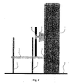
- Fig. 1 shows a side view of an exemplifying embodiment of the positioning device according to the invention
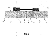
- Fig. 2 shows a plan view of the exemplifying embodiment of the positioning device according to the invention.
- the positioning device for adjustment of the acoustic pressure sensor works like this: the height at which the acoustic pressure sensors should be arranged above the surface 4 of the road is to be determined.
- the legs 3 are raised according to the desired height, for example using thread means.
- the positioning device makes changing of the height of the flat template above the surface 4 of the road from 6 to 25 centimeters possible such that the positioning device may be adjusted to any wheel size and any tire size.
- the flat template 2 is arranged with its inner edge 5 adjacent to the tire 1 of the wheel. Then, the vertical bar 6 is moved in the holder 7 to allow central attachment of the positioning device to the hub of the wheel.
- the holder 7 When the holder 7 is centrally attached to the mounting hub of the wheel and the legs 3 are set such that the flat template 2 stands with its legs 3 on the surface 4 of the road, the holder 7 is locked on the vertical bar 6 and it is possible to start the positioning.
- the acoustic pressure sensors are arranged on hinged holders (not-shown). The joints of these holders will be unlocked and the tops of the acoustic pressure sensors will be seated into the individual marks 9 , while the sensors will be pointed along the lines 10 on the fiat template 2 towards the intersection of the lines 10 , so that the vertical projection of the axis of the acoustic pressure sensor into the plane of the flat template 2 matches the respective lins 10 .
- the acoustic pressure sensors will have to be manually set in one plane only, i.e. in the plane defined by the axis of the acoustic pressure sensor and by the respective line 10 .
- the acoustic pressure sensor gets pointed to the point of contact between the closest part of the tire 1 and the measured surface 4 of the road.
- the legs 3 will be released from the flat template 2 and the holder 7 , which has been attached to the hub of the wheel, so that the flat template 2 can be safety withdrawn from the area surrounding the tire 1 without accidentally hitting any of the acoustic pressure sensors.
- the invention may be used when preparing measurement of level of acoustic pressure emitted by the tires of the wheels during a drive on the surface of a measured road.
Landscapes
- Physics & Mathematics (AREA)
- General Physics & Mathematics (AREA)
- Engineering & Computer Science (AREA)
- General Engineering & Computer Science (AREA)
- Mechanical Engineering (AREA)
- Measuring Fluid Pressure (AREA)
- Measurement Of Mechanical Vibrations Or Ultrasonic Waves (AREA)
- Length Measuring Devices Characterised By Use Of Acoustic Means (AREA)
Abstract
Description
- The technical invention relates to a positioning device for adjusting acoustic pressure sensors on a trailer for measuring acoustic pressure emitted by tires of wheels of the trailer while it is driving on a measured surface of a road.
- Trailers of the above mentioned type are used for measuring acoustic pressure level generated at the interface of a tested road surface / a reference tire at one or more reference speeds, the measurement is done by using the "Close Proximity Method", which is a measurement at a small distance from the source of the acoustic pressure. This method is described in detail in the draft of standard 150/CD11819-2. For each reference tire and for each test ride with the tire the average noise levels and the vehicle speed at each 20 m long test segments are recorded. The noise level is then normalized with respect to the reference speed by conversion and the resulting average noise level for each measuring microphone at the respective reference speed is called a noise level or an acoustic pressure level at the interface tire / road. Results for each type of the reference tires may be converted then into a one-digit CPXI index that can be used to compare acoustic properties of various road surfaces.
- The acoustic pressure level has to be sensed by at least two microphones at each wheel. A special measuring self-propelled vehicle or a measuring trailer pulled by a regular vehicle is used for the measurement. There are reference test tires mounted on the wheels and the test vehicle / trailer may have single wheels or more wheels arranged next to each other. The use of the self-propelled measuring vehicle is limited by a requirement that the microphones should not be arranged near to the driven or controlled wheel while the distance between the microphones and the wheels which are not measured should be at least 1.5 m and in addition the lower part of the vehicle has to be covered with a sound absorbing material to prevent any sound reflections which could influence the results of the measurement.
- For a precise measurement of tire noise several acoustic pressure sensors are used, usually directional microphones, and it is very important that these directional microphones are pointed towards the place where the noise origins, i.e, towards the point of contact between the measured tire and the tested road surface and that the microphones are in a pre-determined distance from the source of the acoustic pressure. This work is complex and lengthy, because it is necessary to adjust a number of independent variables simultaneously, namely the height of the directional microphones above the tested road surface, the translation of the directional microphones with respect to the wheel axis and spatial positioning of the directional microphones so that they are be pointed towards the point of contact between the tire and the surface of the road.
- The goal of the technical invention is to design an equipment for a trailer for positioning acoustic pressure sensors before measuring the acoustic pressure emitted by the tires so that the acoustic pressure sensors could be easily pointed to the point of contact between the tire and the road surface and fixed in that position.
- Said problem is solved by a positioning device for positioning of acoustic pressure sensors on a trailer for a measurement of an acoustic pressure emitted by tires of wheels of the trailer while it is driven on a measured surface of a road according to the invention, wherein the positioning device comprises a flat template arranged on legs, the legs having adjustable height to enable an arrangement of the flat template in parallel with the surface of the road, while the flat template is firmly connected to a vertical bar of a holder, which is slidably arranged on the bar to enable a central attachment of the positioning device to the hub of the wheel and the attachment means for slidably attaching the holder to the vertical bar is lockable.
- According to a preferred embodiment the template is provided at its outer edge with marks for placing the acoustic pressure sensors and with lines extending from said marks on the template and having a common point of intersection for directing the acoustic pressure sensors towards the point of contact between the closest part of the tire and the measured surface of the road. Preferably, the marks for placing the acoustic pressures sensors are indentations for both receiving the acoustic pressure sensors and for their fixation in the set position,
- According to a further embodiment of the invention, the template is arranged on four legs, wherein the distance between the template and the surface of the road is adjustable in the range from 6 to 25 centimeters by means of the legs.
- According to a further embodiment of the invention the marks for placing the acoustic pressure sensors are arranged symmetrically with respect to the axis of the wheel and evenly spaced from each other, preferably 15 to 25 centimeters.
- According to a further embodiment of the invention the template is provided with a ruler at its outer edge.
- According to a most preferred embodiment the acoustic pressure sensors are directional microphones.
- The technical solution will be further described in detail with reference to the attached Figures, wherein
Fig. 1 shows a side view of an exemplifying embodiment of the positioning device according to the invention andFig. 2 shows a plan view of the exemplifying embodiment of the positioning device according to the invention. -
-
Fig. 1 shows a side view of an exemplifying embodiment of the positioning device for adjusting acoustic pressure sensors, as viewed in the travel direction of the trailer. The acoustic pressure sensors (not shown) are attached to a bar of the trailer (not shown). Said bar is arranged in parallel to the direction of travel of the trailer during measuring of the acoustic pressure level emitted by the tires 1 of its wheels while driving it on a measured surface of a road. The positioning device contains aflat template 2 placed onlegs 3 having adjustable height which enable an arrangement of theflat template 2 in parallel with a road surface 4 , Aninner edge 5 of theflat template 2 abuts the tire 1 of the wheel and theflat template 2 is firmly attached to a vertical bar 6 of a holder 7 , wherein a holder 7 for a central attachment of the positioning device to the hub of the wheel is slidably attached to the bar 6 . The slidable connection of the holder 7 and the vertical bar 6 may be locked by a locking device (not-shown). The distance between theflat template 2 and the road surface 4 may be adjusted in a range of 6 to 25 centimeters by means of thelegs 3 -
Fig. 2 shows a plan view of the exemplifying embodiment of the positioning device for positioning of acoustic pressure sensors. Theinner edge 5 of theflat template 2 abuts the tire 1 of the wheel and theflat template 2 is provided at itsouter edge 8 withmarks 9 for placing the acoustic pressure sensors, andlines 10 extend from thesemarks 9 on theflat template 2 towards a common point of intersection for directing the acoustic pressure sensors towards the point of contact between the closest part of the tire 1 and the measured surface 4 of the road. Themarks 9 for placing the acoustic pressure sensors are usually indentations for both an receiving the acoustic pressure sensors and for fixing those in a set position. Themarks 9 for placing the acoustic pressure sensors are arranged usually symmetrically with respect to the axis of the wheel and the tire 1 , they are evenly spaced from each other, the spacing being in the range from 15 to 25 cm, preferably 20 centimeters. Theflat template 2 is provided with a ruler (not shown) at itsouter edge 8 , using which it is possible to read the distance between arespective mark 9 and the middle of theflat template 2 , or to move an acoustic pressure sensor in a defined way along theouter edge 8 of theflat template 2 . Directional microphones are most commonly used as the acoustic pressure sensors. - In operation the positioning device for adjustment of the acoustic pressure sensor works like this: the height at which the acoustic pressure sensors should be arranged above the surface 4 of the road is to be determined. The
legs 3 are raised according to the desired height, for example using thread means. According to the exemplifying embodiment the positioning device makes changing of the height of the flat template above the surface 4 of the road from 6 to 25 centimeters possible such that the positioning device may be adjusted to any wheel size and any tire size. Theflat template 2 is arranged with itsinner edge 5 adjacent to the tire 1 of the wheel. Then, the vertical bar 6 is moved in the holder 7 to allow central attachment of the positioning device to the hub of the wheel. When the holder 7 is centrally attached to the mounting hub of the wheel and thelegs 3 are set such that theflat template 2 stands with itslegs 3 on the surface 4 of the road, the holder 7 is locked on the vertical bar 6 and it is possible to start the positioning. The acoustic pressure sensors are arranged on hinged holders (not-shown). The joints of these holders will be unlocked and the tops of the acoustic pressure sensors will be seated into theindividual marks 9 , while the sensors will be pointed along thelines 10 on thefiat template 2 towards the intersection of thelines 10 , so that the vertical projection of the axis of the acoustic pressure sensor into the plane of theflat template 2 matches therespective lins 10. Then, the acoustic pressure sensors will have to be manually set in one plane only, i.e. in the plane defined by the axis of the acoustic pressure sensor and by therespective line 10 . By this manual setting, the acoustic pressure sensor gets pointed to the point of contact between the closest part of the tire 1 and the measured surface 4 of the road. After setting the individual acoustic pressure sensors, thelegs 3 will be released from theflat template 2 and the holder 7 , which has been attached to the hub of the wheel, so that theflat template 2 can be safety withdrawn from the area surrounding the tire 1 without accidentally hitting any of the acoustic pressure sensors. - Use of the positioning device for positioning of acoustic pressure sensors reduces the time needed for positioning the acoustic pressure sensors significantly and it makes the result of such positioning much more accurate.
- The invention may be used when preparing measurement of level of acoustic pressure emitted by the tires of the wheels during a drive on the surface of a measured road.
Claims (8)
- Positioning device for positioning of acoustic pressure sensors on a trailer for a measurement of an acoustic pressure emitted by tires (1) of wheels (2) of the trailer while it is driven on a measured surface (3) of a road characterized in that the positioning device comprises a flat template (5) arranged on legs (6), the legs (6) having adjustable height to enable an arrangement of the flat template (5) in parallel with the surface (3) of the road, while the flat template (5) is firmly connected to a vertical bar (7) of a holder (4), which is slidably arranged on the bar (7) to enable a central attachment of the positioning device to the hub of the wheel (2) and the attachment means for slidably attaching the holder (4) to the vertical bar (7) is lockable.
- The positioning device according to claim 1, characterized in that the template (5) is provided at its outer edge with marks for placing the acoustic pressure sensors and with lines extending from said marks on the template (5) and having a common point of intersection for directing the acoustic pressure sensors towards the point of contact between the closet part of the tire and the measured surface (3) of the road.
- The positioning device according to claim 2, characterized in that the marks for placing the acoustic pressures sensors are indentations for both receiving the acoustic pressure sensors and for their fixation in the set position.
- The positioning device according to claim 1, characterized In that the distance between the template (5) and the surface (3) of the road is adjustable by means of the legs (6) in the range from 6 to 25 centimeters.
- The positioning device according to claim 1, characterized in that the marks for placing the acoustic pressure sensors are arranged symmetrically with respect to the axis of the wheel (2) and evenly spaced from each other.
- The positioning device according to claim 5, characterized in that the spacing between the marks for placing the acoustic pressure sensors is in a range from 15 to 25 centimeters.
- The positioning device according to claim 1 or 2, characterized in that the template (5) is provided with a ruler at its outer edge.
- The positioning device according to claim 1, characterized in that the acoustic pressure sensors are directional microphones.
Applications Claiming Priority (1)
| Application Number | Priority Date | Filing Date | Title |
|---|---|---|---|
| CZ20110826A CZ2011826A3 (en) | 2011-12-15 | 2011-12-15 | Setting device |
Publications (3)
| Publication Number | Publication Date |
|---|---|
| EP2604994A2 true EP2604994A2 (en) | 2013-06-19 |
| EP2604994A3 EP2604994A3 (en) | 2016-02-17 |
| EP2604994B1 EP2604994B1 (en) | 2017-01-04 |
Family
ID=45654760
Family Applications (1)
| Application Number | Title | Priority Date | Filing Date |
|---|---|---|---|
| EP12000426.2A Not-in-force EP2604994B1 (en) | 2011-12-15 | 2012-01-24 | Sensor positioning device |
Country Status (4)
| Country | Link |
|---|---|
| US (2) | US20130168513A1 (en) |
| EP (1) | EP2604994B1 (en) |
| JP (1) | JP6164827B2 (en) |
| CZ (1) | CZ2011826A3 (en) |
Cited By (1)
| Publication number | Priority date | Publication date | Assignee | Title |
|---|---|---|---|---|
| CN112066210A (en) * | 2020-08-18 | 2020-12-11 | 蔡君亮 | Assembly type building construction noise pollution detection device |
Families Citing this family (4)
| Publication number | Priority date | Publication date | Assignee | Title |
|---|---|---|---|---|
| CN106441699B (en) * | 2016-08-30 | 2022-05-17 | 重庆长安民生物流股份有限公司 | Automobile tire pressure detection device |
| JP7133458B2 (en) * | 2018-12-17 | 2022-09-08 | Toyo Tire株式会社 | Sound source identification method |
| JP7185565B2 (en) * | 2019-03-07 | 2022-12-07 | Toyo Tire株式会社 | Method for estimating tire test results |
| CN112728309A (en) * | 2020-12-22 | 2021-04-30 | 中国船舶重工集团公司第七0三研究所 | Vibration sensor support for gas turbine |
Family Cites Families (20)
| Publication number | Priority date | Publication date | Assignee | Title |
|---|---|---|---|---|
| US2678559A (en) * | 1951-12-29 | 1954-05-18 | Sperry Prod Inc | Ultrasonic rail test device |
| JPS5961721A (en) * | 1982-10-01 | 1984-04-09 | Bridgestone Corp | Method and apparatus for searching sound source |
| US4723444A (en) * | 1986-09-17 | 1988-02-09 | Jaroslav Hajek | Apparatus for determining side-slip characteristics of a moving vehicle |
| US6799470B2 (en) * | 1987-02-04 | 2004-10-05 | Kabushiki Kaisha Haradakuni | Lateral force-measuring device for a wheel, lateral force-measuring method, and vehicle-inspecting system having the device |
| JPH06174543A (en) * | 1992-12-03 | 1994-06-24 | Toyota Motor Corp | Detecting apparatus for road surface condition |
| JPH0755649A (en) * | 1993-08-23 | 1995-03-03 | Bridgestone Corp | Method of testing noise of tire |
| US5515726A (en) * | 1994-12-27 | 1996-05-14 | Chrysler Corporation | Vehicle wheel cover noise testing machine |
| US5561244A (en) * | 1995-03-10 | 1996-10-01 | Bridgestone/Firestone, Inc. | Method and apparatus for measuring the dynamic camber of vehicle tires |
| JP3473158B2 (en) * | 1995-03-22 | 2003-12-02 | 住友電気工業株式会社 | Road surface condition detection device |
| JPH0954020A (en) * | 1995-08-10 | 1997-02-25 | Sumitomo Electric Ind Ltd | Road condition detector |
| JP2002243535A (en) * | 2001-02-20 | 2002-08-28 | Omron Corp | Road condition detector |
| JP3874705B2 (en) * | 2002-07-26 | 2007-01-31 | ニッケン株式会社 | Vehicle running sound tester |
| US6739186B1 (en) * | 2002-08-14 | 2004-05-25 | The Goodyear Tire & Rubber Company | Tire and rim assembly centering method |
| US6981419B1 (en) * | 2003-05-15 | 2006-01-03 | Hay D Robert | Portable direct sensor attachment system |
| FR2866114B1 (en) * | 2004-02-11 | 2006-05-05 | Airbus France | MOBILE TEST BENCH FOR TIRES, AND METHOD FOR IMPLEMENTING SUCH A TEST BENCH |
| DE102005012702B3 (en) * | 2005-03-11 | 2006-09-14 | Forschungsinstitut für Kraftfahrwesen und Fahrzeugmotoren Stuttgart (FKFS) | Method of determining a noise component caused by a wheel of a vehicle rolling on a road surface from all the noise in the vehicle |
| US7775096B2 (en) * | 2008-10-15 | 2010-08-17 | The Goodyear Tire & Rubber Company | Wheel based sensor assembly |
| CN101762319B (en) * | 2008-12-24 | 2011-11-09 | 交通部公路科学研究院 | Balance weight tyre and road noise detecting trailer |
| ES2389916T3 (en) * | 2009-01-22 | 2012-11-05 | Snap-On Equipment Srl A Unico Socio | Wheel diagnostic system |
| US8113040B2 (en) * | 2009-07-13 | 2012-02-14 | K-Line Industries, Inc. | Tire runout gauge |
-
2011
- 2011-12-15 CZ CZ20110826A patent/CZ2011826A3/en unknown
-
2012
- 2012-01-24 EP EP12000426.2A patent/EP2604994B1/en not_active Not-in-force
- 2012-12-06 JP JP2012267546A patent/JP6164827B2/en not_active Expired - Fee Related
- 2012-12-13 US US13/713,580 patent/US20130168513A1/en not_active Abandoned
-
2014
- 2014-06-05 US US14/296,881 patent/US20150114147A1/en not_active Abandoned
Non-Patent Citations (1)
| Title |
|---|
| None |
Cited By (1)
| Publication number | Priority date | Publication date | Assignee | Title |
|---|---|---|---|---|
| CN112066210A (en) * | 2020-08-18 | 2020-12-11 | 蔡君亮 | Assembly type building construction noise pollution detection device |
Also Published As
| Publication number | Publication date |
|---|---|
| JP6164827B2 (en) | 2017-07-19 |
| US20150114147A1 (en) | 2015-04-30 |
| US20130168513A1 (en) | 2013-07-04 |
| JP2013125030A (en) | 2013-06-24 |
| EP2604994A3 (en) | 2016-02-17 |
| CZ2011826A3 (en) | 2013-06-26 |
| EP2604994B1 (en) | 2017-01-04 |
Similar Documents
| Publication | Publication Date | Title |
|---|---|---|
| US20150114147A1 (en) | Positioning device | |
| US8020307B2 (en) | Alignment system and method for vehicle-mounted devices | |
| CN112313112B (en) | System and method for determining position and/or orientation of a container of a switch | |
| US7874078B2 (en) | Vehicle dimensional measuring system | |
| CN104848785B (en) | A kind of vehicle complete vehicle parameter test system | |
| IT201900001167A1 (en) | APPARATUS FOR CALIBRATING A SENSOR OF AN ADVANCED ASSISTANCE SYSTEM DRIVING A VEHICLE | |
| US9821849B2 (en) | Wheel alignment and toe angle adjustment system for a three-wheeled vehicle | |
| CN105881101B (en) | The detection device and its control method of wheel hub | |
| US9587937B2 (en) | Construction machine with setup assistance system for a sensor unit | |
| WO2017101912A4 (en) | Device for calibrating at least one radar sensor | |
| KR101480525B1 (en) | Tripod fixing apparatus for geodetic surveying instrument | |
| JPS63172938A (en) | Wheel aligner for car | |
| US11835332B2 (en) | Device and method for detecting the steering wheel position, the steering wheel angle and the inclination of the steering wheel of a vehicle | |
| KR20130044780A (en) | Testing device for performance characteristics of speed sensor | |
| IT201900013173A1 (en) | METHOD AND APPARATUS FOR CALIBRATING A VEHICLE ADAS SENSOR | |
| CA2677959C (en) | Object alignment device and method | |
| CN107883905A (en) | Turntable for coordinate measuring machine | |
| JP6946237B2 (en) | Marker installation system and method | |
| KR101809648B1 (en) | Apparatus for maintaining target upright for geodetic surveying | |
| US7391303B2 (en) | Object alignment device and method | |
| CN216010079U (en) | Positioning device for garden construction | |
| US11960024B2 (en) | Angle measurement system for automotive collision avoidance sensors | |
| CA2337552C (en) | Tool and method for measuring the ride height of a vehicle | |
| US1601261A (en) | Device for testing wheel cant | |
| CN216013641U (en) | Device for calibrating vehicle-mounted radar and camera |
Legal Events
| Date | Code | Title | Description |
|---|---|---|---|
| PUAI | Public reference made under article 153(3) epc to a published international application that has entered the european phase |
Free format text: ORIGINAL CODE: 0009012 |
|
| AK | Designated contracting states |
Kind code of ref document: A2 Designated state(s): AL AT BE BG CH CY CZ DE DK EE ES FI FR GB GR HR HU IE IS IT LI LT LU LV MC MK MT NL NO PL PT RO RS SE SI SK SM TR |
|
| AX | Request for extension of the european patent |
Extension state: BA ME |
|
| PUAL | Search report despatched |
Free format text: ORIGINAL CODE: 0009013 |
|
| AK | Designated contracting states |
Kind code of ref document: A3 Designated state(s): AL AT BE BG CH CY CZ DE DK EE ES FI FR GB GR HR HU IE IS IT LI LT LU LV MC MK MT NL NO PL PT RO RS SE SI SK SM TR |
|
| AX | Request for extension of the european patent |
Extension state: BA ME |
|
| RIC1 | Information provided on ipc code assigned before grant |
Ipc: G01L 17/00 20060101ALI20160113BHEP Ipc: F16M 13/00 20060101ALI20160113BHEP Ipc: G01M 17/02 20060101AFI20160113BHEP |
|
| 17P | Request for examination filed |
Effective date: 20160329 |
|
| RBV | Designated contracting states (corrected) |
Designated state(s): AL AT BE BG CH CY CZ DE DK EE ES FI FR GB GR HR HU IE IS IT LI LT LU LV MC MK MT NL NO PL PT RO RS SE SI SK SM TR |
|
| GRAP | Despatch of communication of intention to grant a patent |
Free format text: ORIGINAL CODE: EPIDOSNIGR1 |
|
| INTG | Intention to grant announced |
Effective date: 20160713 |
|
| GRAS | Grant fee paid |
Free format text: ORIGINAL CODE: EPIDOSNIGR3 |
|
| GRAA | (expected) grant |
Free format text: ORIGINAL CODE: 0009210 |
|
| AK | Designated contracting states |
Kind code of ref document: B1 Designated state(s): AL AT BE BG CH CY CZ DE DK EE ES FI FR GB GR HR HU IE IS IT LI LT LU LV MC MK MT NL NO PL PT RO RS SE SI SK SM TR |
|
| REG | Reference to a national code |
Ref country code: GB Ref legal event code: FG4D |
|
| REG | Reference to a national code |
Ref country code: CH Ref legal event code: EP |
|
| REG | Reference to a national code |
Ref country code: AT Ref legal event code: REF Ref document number: 859718 Country of ref document: AT Kind code of ref document: T Effective date: 20170115 |
|
| REG | Reference to a national code |
Ref country code: IE Ref legal event code: FG4D |
|
| REG | Reference to a national code |
Ref country code: FR Ref legal event code: PLFP Year of fee payment: 6 |
|
| REG | Reference to a national code |
Ref country code: DE Ref legal event code: R096 Ref document number: 602012027254 Country of ref document: DE |
|
| REG | Reference to a national code |
Ref country code: LT Ref legal event code: MG4D Ref country code: NL Ref legal event code: MP Effective date: 20170104 |
|
| PG25 | Lapsed in a contracting state [announced via postgrant information from national office to epo] |
Ref country code: BE Free format text: LAPSE BECAUSE OF NON-PAYMENT OF DUE FEES Effective date: 20170131 |
|
| REG | Reference to a national code |
Ref country code: AT Ref legal event code: MK05 Ref document number: 859718 Country of ref document: AT Kind code of ref document: T Effective date: 20170104 |
|
| PG25 | Lapsed in a contracting state [announced via postgrant information from national office to epo] |
Ref country code: NL Free format text: LAPSE BECAUSE OF FAILURE TO SUBMIT A TRANSLATION OF THE DESCRIPTION OR TO PAY THE FEE WITHIN THE PRESCRIBED TIME-LIMIT Effective date: 20170104 |
|
| PG25 | Lapsed in a contracting state [announced via postgrant information from national office to epo] |
Ref country code: FI Free format text: LAPSE BECAUSE OF FAILURE TO SUBMIT A TRANSLATION OF THE DESCRIPTION OR TO PAY THE FEE WITHIN THE PRESCRIBED TIME-LIMIT Effective date: 20170104 Ref country code: LT Free format text: LAPSE BECAUSE OF FAILURE TO SUBMIT A TRANSLATION OF THE DESCRIPTION OR TO PAY THE FEE WITHIN THE PRESCRIBED TIME-LIMIT Effective date: 20170104 Ref country code: NO Free format text: LAPSE BECAUSE OF FAILURE TO SUBMIT A TRANSLATION OF THE DESCRIPTION OR TO PAY THE FEE WITHIN THE PRESCRIBED TIME-LIMIT Effective date: 20170404 Ref country code: GR Free format text: LAPSE BECAUSE OF FAILURE TO SUBMIT A TRANSLATION OF THE DESCRIPTION OR TO PAY THE FEE WITHIN THE PRESCRIBED TIME-LIMIT Effective date: 20170405 Ref country code: IS Free format text: LAPSE BECAUSE OF FAILURE TO SUBMIT A TRANSLATION OF THE DESCRIPTION OR TO PAY THE FEE WITHIN THE PRESCRIBED TIME-LIMIT Effective date: 20170504 Ref country code: HR Free format text: LAPSE BECAUSE OF FAILURE TO SUBMIT A TRANSLATION OF THE DESCRIPTION OR TO PAY THE FEE WITHIN THE PRESCRIBED TIME-LIMIT Effective date: 20170104 |
|
| REG | Reference to a national code |
Ref country code: DE Ref legal event code: R119 Ref document number: 602012027254 Country of ref document: DE |
|
| PG25 | Lapsed in a contracting state [announced via postgrant information from national office to epo] |
Ref country code: BG Free format text: LAPSE BECAUSE OF FAILURE TO SUBMIT A TRANSLATION OF THE DESCRIPTION OR TO PAY THE FEE WITHIN THE PRESCRIBED TIME-LIMIT Effective date: 20170404 Ref country code: RS Free format text: LAPSE BECAUSE OF FAILURE TO SUBMIT A TRANSLATION OF THE DESCRIPTION OR TO PAY THE FEE WITHIN THE PRESCRIBED TIME-LIMIT Effective date: 20170104 Ref country code: AT Free format text: LAPSE BECAUSE OF FAILURE TO SUBMIT A TRANSLATION OF THE DESCRIPTION OR TO PAY THE FEE WITHIN THE PRESCRIBED TIME-LIMIT Effective date: 20170104 Ref country code: LV Free format text: LAPSE BECAUSE OF FAILURE TO SUBMIT A TRANSLATION OF THE DESCRIPTION OR TO PAY THE FEE WITHIN THE PRESCRIBED TIME-LIMIT Effective date: 20170104 Ref country code: PT Free format text: LAPSE BECAUSE OF FAILURE TO SUBMIT A TRANSLATION OF THE DESCRIPTION OR TO PAY THE FEE WITHIN THE PRESCRIBED TIME-LIMIT Effective date: 20170504 Ref country code: SE Free format text: LAPSE BECAUSE OF FAILURE TO SUBMIT A TRANSLATION OF THE DESCRIPTION OR TO PAY THE FEE WITHIN THE PRESCRIBED TIME-LIMIT Effective date: 20170104 Ref country code: PL Free format text: LAPSE BECAUSE OF FAILURE TO SUBMIT A TRANSLATION OF THE DESCRIPTION OR TO PAY THE FEE WITHIN THE PRESCRIBED TIME-LIMIT Effective date: 20170104 Ref country code: ES Free format text: LAPSE BECAUSE OF FAILURE TO SUBMIT A TRANSLATION OF THE DESCRIPTION OR TO PAY THE FEE WITHIN THE PRESCRIBED TIME-LIMIT Effective date: 20170104 |
|
| REG | Reference to a national code |
Ref country code: CH Ref legal event code: PL |
|
| PG25 | Lapsed in a contracting state [announced via postgrant information from national office to epo] |
Ref country code: CZ Free format text: LAPSE BECAUSE OF FAILURE TO SUBMIT A TRANSLATION OF THE DESCRIPTION OR TO PAY THE FEE WITHIN THE PRESCRIBED TIME-LIMIT Effective date: 20170104 Ref country code: EE Free format text: LAPSE BECAUSE OF FAILURE TO SUBMIT A TRANSLATION OF THE DESCRIPTION OR TO PAY THE FEE WITHIN THE PRESCRIBED TIME-LIMIT Effective date: 20170104 Ref country code: LI Free format text: LAPSE BECAUSE OF NON-PAYMENT OF DUE FEES Effective date: 20170131 Ref country code: IT Free format text: LAPSE BECAUSE OF FAILURE TO SUBMIT A TRANSLATION OF THE DESCRIPTION OR TO PAY THE FEE WITHIN THE PRESCRIBED TIME-LIMIT Effective date: 20170104 Ref country code: CH Free format text: LAPSE BECAUSE OF NON-PAYMENT OF DUE FEES Effective date: 20170131 Ref country code: SK Free format text: LAPSE BECAUSE OF FAILURE TO SUBMIT A TRANSLATION OF THE DESCRIPTION OR TO PAY THE FEE WITHIN THE PRESCRIBED TIME-LIMIT Effective date: 20170104 Ref country code: RO Free format text: LAPSE BECAUSE OF FAILURE TO SUBMIT A TRANSLATION OF THE DESCRIPTION OR TO PAY THE FEE WITHIN THE PRESCRIBED TIME-LIMIT Effective date: 20170104 |
|
| REG | Reference to a national code |
Ref country code: IE Ref legal event code: MM4A |
|
| PLBE | No opposition filed within time limit |
Free format text: ORIGINAL CODE: 0009261 |
|
| STAA | Information on the status of an ep patent application or granted ep patent |
Free format text: STATUS: NO OPPOSITION FILED WITHIN TIME LIMIT |
|
| PG25 | Lapsed in a contracting state [announced via postgrant information from national office to epo] |
Ref country code: LU Free format text: LAPSE BECAUSE OF NON-PAYMENT OF DUE FEES Effective date: 20170124 Ref country code: DK Free format text: LAPSE BECAUSE OF FAILURE TO SUBMIT A TRANSLATION OF THE DESCRIPTION OR TO PAY THE FEE WITHIN THE PRESCRIBED TIME-LIMIT Effective date: 20170104 Ref country code: SM Free format text: LAPSE BECAUSE OF FAILURE TO SUBMIT A TRANSLATION OF THE DESCRIPTION OR TO PAY THE FEE WITHIN THE PRESCRIBED TIME-LIMIT Effective date: 20170104 Ref country code: DE Free format text: LAPSE BECAUSE OF NON-PAYMENT OF DUE FEES Effective date: 20170801 Ref country code: MC Free format text: LAPSE BECAUSE OF FAILURE TO SUBMIT A TRANSLATION OF THE DESCRIPTION OR TO PAY THE FEE WITHIN THE PRESCRIBED TIME-LIMIT Effective date: 20170104 |
|
| 26N | No opposition filed |
Effective date: 20171005 |
|
| GBPC | Gb: european patent ceased through non-payment of renewal fee |
Effective date: 20170404 |
|
| REG | Reference to a national code |
Ref country code: FR Ref legal event code: PLFP Year of fee payment: 7 |
|
| REG | Reference to a national code |
Ref country code: BE Ref legal event code: MM Effective date: 20170131 |
|
| PG25 | Lapsed in a contracting state [announced via postgrant information from national office to epo] |
Ref country code: GB Free format text: LAPSE BECAUSE OF NON-PAYMENT OF DUE FEES Effective date: 20170404 Ref country code: SI Free format text: LAPSE BECAUSE OF FAILURE TO SUBMIT A TRANSLATION OF THE DESCRIPTION OR TO PAY THE FEE WITHIN THE PRESCRIBED TIME-LIMIT Effective date: 20170104 Ref country code: IE Free format text: LAPSE BECAUSE OF NON-PAYMENT OF DUE FEES Effective date: 20170124 |
|
| PG25 | Lapsed in a contracting state [announced via postgrant information from national office to epo] |
Ref country code: MT Free format text: LAPSE BECAUSE OF NON-PAYMENT OF DUE FEES Effective date: 20170124 |
|
| PG25 | Lapsed in a contracting state [announced via postgrant information from national office to epo] |
Ref country code: HU Free format text: LAPSE BECAUSE OF FAILURE TO SUBMIT A TRANSLATION OF THE DESCRIPTION OR TO PAY THE FEE WITHIN THE PRESCRIBED TIME-LIMIT; INVALID AB INITIO Effective date: 20120124 |
|
| PG25 | Lapsed in a contracting state [announced via postgrant information from national office to epo] |
Ref country code: CY Free format text: LAPSE BECAUSE OF NON-PAYMENT OF DUE FEES Effective date: 20170104 |
|
| PG25 | Lapsed in a contracting state [announced via postgrant information from national office to epo] |
Ref country code: MK Free format text: LAPSE BECAUSE OF FAILURE TO SUBMIT A TRANSLATION OF THE DESCRIPTION OR TO PAY THE FEE WITHIN THE PRESCRIBED TIME-LIMIT Effective date: 20170104 |
|
| PG25 | Lapsed in a contracting state [announced via postgrant information from national office to epo] |
Ref country code: TR Free format text: LAPSE BECAUSE OF FAILURE TO SUBMIT A TRANSLATION OF THE DESCRIPTION OR TO PAY THE FEE WITHIN THE PRESCRIBED TIME-LIMIT Effective date: 20170104 |
|
| PGFP | Annual fee paid to national office [announced via postgrant information from national office to epo] |
Ref country code: FR Payment date: 20200121 Year of fee payment: 9 |
|
| PG25 | Lapsed in a contracting state [announced via postgrant information from national office to epo] |
Ref country code: AL Free format text: LAPSE BECAUSE OF FAILURE TO SUBMIT A TRANSLATION OF THE DESCRIPTION OR TO PAY THE FEE WITHIN THE PRESCRIBED TIME-LIMIT Effective date: 20170104 |
|
| PG25 | Lapsed in a contracting state [announced via postgrant information from national office to epo] |
Ref country code: FR Free format text: LAPSE BECAUSE OF NON-PAYMENT OF DUE FEES Effective date: 20210131 |