JP6164827B2 - Positioning device - Google Patents
Positioning device Download PDFInfo
- Publication number
- JP6164827B2 JP6164827B2 JP2012267546A JP2012267546A JP6164827B2 JP 6164827 B2 JP6164827 B2 JP 6164827B2 JP 2012267546 A JP2012267546 A JP 2012267546A JP 2012267546 A JP2012267546 A JP 2012267546A JP 6164827 B2 JP6164827 B2 JP 6164827B2
- Authority
- JP
- Japan
- Prior art keywords
- sound pressure
- pressure sensor
- positioning device
- horizontal member
- flat horizontal
- Prior art date
- Legal status (The legal status is an assumption and is not a legal conclusion. Google has not performed a legal analysis and makes no representation as to the accuracy of the status listed.)
- Expired - Fee Related
Links
Images

Classifications
-
- G—PHYSICS
- G01—MEASURING; TESTING
- G01L—MEASURING FORCE, STRESS, TORQUE, WORK, MECHANICAL POWER, MECHANICAL EFFICIENCY, OR FLUID PRESSURE
- G01L17/00—Devices or apparatus for measuring tyre pressure or the pressure in other inflated bodies
-
- G—PHYSICS
- G01—MEASURING; TESTING
- G01M—TESTING STATIC OR DYNAMIC BALANCE OF MACHINES OR STRUCTURES; TESTING OF STRUCTURES OR APPARATUS, NOT OTHERWISE PROVIDED FOR
- G01M17/00—Testing of vehicles
- G01M17/007—Wheeled or endless-tracked vehicles
- G01M17/02—Tyres
- G01M17/025—Tyres using infrasonic, sonic or ultrasonic vibrations
-
- F—MECHANICAL ENGINEERING; LIGHTING; HEATING; WEAPONS; BLASTING
- F16—ENGINEERING ELEMENTS AND UNITS; GENERAL MEASURES FOR PRODUCING AND MAINTAINING EFFECTIVE FUNCTIONING OF MACHINES OR INSTALLATIONS; THERMAL INSULATION IN GENERAL
- F16M—FRAMES, CASINGS OR BEDS OF ENGINES, MACHINES OR APPARATUS, NOT SPECIFIC TO ENGINES, MACHINES OR APPARATUS PROVIDED FOR ELSEWHERE; STANDS; SUPPORTS
- F16M13/00—Other supports for positioning apparatus or articles; Means for steadying hand-held apparatus or articles
Description
本技術発明は,道路の測定表面上を走行中にトレーラの車輪のタイヤが発する音圧を測定するために,トレーラ上で音圧センサを調整する位置決め装置に関する。 The present invention relates to a positioning device for adjusting a sound pressure sensor on a trailer in order to measure a sound pressure generated by a tire of a trailer wheel while traveling on a measurement surface of a road.
技術水準
上記タイプのトレーラを1又はそれ以上の基準速度で試験路面/基準タイヤの接触面で生じた音圧レベルを測定するために使用し,測定は音圧源から近距離での測定法である「近接測定法(Close Proximity Method)」を利用して行う。この方法はISO/CD11819‐2の規格案に詳細に記載されている。各基準タイヤ及び該タイヤでの各試乗のために,各20m長の試験区分における平均騒音レベル及び車両速度を記録する。その後,変換によって基準速度に対する騒音レベルを平常値にし,各基準速度において,各測定マイクで得られた平均騒音レベルは,タイヤ/道路の接触面での騒音レベル又は音圧レベルと称する。その後,基準タイヤの各タイプでの結果を,様々な路面の音響特性と比較するために使用可能な1桁のCPXI指数に変換してもよい。
State of the art A trailer of the above type is used to measure the sound pressure level produced at the contact surface of the test road / reference tire at one or more reference speeds. This is done using a certain "Close Proximity Method". This method is described in detail in the draft ISO / CD11819-2 standard. For each reference tire and each test ride on that tire, record the average noise level and vehicle speed in each 20m long test section. Thereafter, the noise level with respect to the reference speed is converted into a normal value by conversion, and the average noise level obtained with each measurement microphone at each reference speed is referred to as a noise level or a sound pressure level at the tire / road contact surface. The results for each type of reference tire may then be converted to a single digit CPXI index that can be used to compare the acoustic characteristics of various road surfaces.
音圧レベルは,各車輪で少なくとも2本のマイクにより感知させなければならない。特別な測定用自走式車両又は普通車に牽引された測定用トレーラを測定に使用する。車輪には基準試験タイヤが装着されており,試験車両/トレーラは,単輪又は互いに隣接させた複輪を有してもよい。マイクを走行又は制御された車輪の近くに設置してはならず,マイクと測定されない車輪との間の距離は少なくとも1.5mであり,更に,測定結果に影響を及ぼし得るあらゆる音波反射を防止するために車両の下部を吸音材料で被覆する必要があるという要件によって自走式測定用車両への使用は制限される。 The sound pressure level must be sensed by at least two microphones at each wheel. A special measuring self-propelled vehicle or a measuring trailer pulled by a normal vehicle is used for the measurement. The wheels are fitted with reference test tires, and the test vehicle / trailer may have a single wheel or multiple wheels adjacent to each other. The microphone must not be installed near a wheel that is being run or controlled, the distance between the microphone and the wheel that is not measured is at least 1.5 m and further prevents any acoustic reflections that may affect the measurement results In order to achieve this, the use of a self-propelled measuring vehicle is limited by the requirement that the lower part of the vehicle must be covered with a sound absorbing material.
タイヤ騒音を正確に測定するため,数個の音圧センサ,通常,指向性マイクを使用し,騒音源,すなわち被測定タイヤと試験路面との間の接触点にこれらの指向性マイクを向けて,音圧の源から所定距離にマイクを置くことは極めて重要である。この作業は複雑で時間が掛かる。何故なら,多数の独立した可変条件,すなわち,試験路面上の指向性マイクの高さ,車軸に対する指向性マイクの移動,及び,指向性マイクをタイヤと路面との間の接触点に向けるための空間配置を同時に調整する必要があるからである。 In order to measure tire noise accurately, several sound pressure sensors, usually directional microphones, are used, and these directional microphones are pointed at the noise source, ie the contact point between the measured tire and the test road surface. It is very important to place the microphone at a predetermined distance from the sound pressure source. This task is complex and time consuming. Because there are a number of independent variable conditions, ie, the height of the directional microphone on the test road surface, the movement of the directional microphone relative to the axle, and the directional microphone pointing to the contact point between the tire and the road surface. This is because it is necessary to adjust the spatial arrangement at the same time.
本技術発明の目的は,音圧センサをタイヤと路面との間の接触点に容易に向かせ,その位置に固定できるように,タイヤが発する音圧を測定する前に音圧センサを位置決めするためのトレーラ用の機器を設計することである。 The object of the present invention is to position the sound pressure sensor before measuring the sound pressure generated by the tire so that the sound pressure sensor can be easily directed to the contact point between the tire and the road surface and fixed at that position. Is to design equipment for trailers.
前記課題は,道路の測定表面上を走行中にトレーラの車輪のタイヤが発する音圧を測定するために,前記トレーラ上に音圧センサを位置決めするための本発明の位置決め装置により解決されるものであり,前記位置決め装置は支柱に設置した平坦な横架材を備え,前記支柱は路面と平行に前記平坦な横架材を設置できるよう高さが調整可能であり,一方,前記平坦な横架材はホルダの垂直杆に堅固に連結され,前記ホルダは車輪のハブの中心に前記位置決め装置を取り付けることができるよう前記垂直杆上に摺動可能に設置され,前記垂直杆に前記ホルダを摺動可能に装着するための装着手段は係止可能であり,前記平坦な横架材の外縁には,前記音圧センサを載置するための複数のマークと,前記平坦な横架材上の前記マークから伸長し,前記車輪のタイヤの最接近部と前記道路の前記測定表面との間の接触点へ前記音圧センサを向けるために,交点という共有点を有するラインとが設けられる。 The problem is solved by the positioning device of the present invention for positioning the sound pressure sensor on the trailer to measure the sound pressure generated by the tires of the trailer wheels while traveling on the measurement surface of the road. The positioning device comprises a flat horizontal member installed on a column, and the column can be adjusted in height so that the flat horizontal member can be installed in parallel to the road surface, while the flat horizontal member is The frame is firmly connected to the vertical rod of the holder, and the holder is slidably installed on the vertical rod so that the positioning device can be attached to the center of the wheel hub, and the holder is attached to the vertical rod. mounting means for slidably mounting the Ri lockable der, wherein the outer edge of the flat template, a plurality of marks for placing the acoustic pressure sensor, the flat template Extending from the mark above, To closest portion of the tire of the serial wheel and directing the sound pressure sensor to the point of contact between the measurement surface of the road, is Ru provided with a line having a common point of intersection.
好適には,前記音圧センサを載置するための前記マークは,前記音圧センサを受容して設定位置に保止固定するための凹条としてある。 The good suitable, the mark for mounting the sound pressure sensor is a concave for Hotome fixed to a set position by receiving the sound pressure sensor.
本発明の更なる実施態様によれば,前記横架材は4本の前記支柱の上に設置され,前記横架材と前記路面との間の距離は,前記支柱により6〜25cmの範囲に調整可能である。 According to a further embodiment of the present invention, the horizontal member is installed on four pillars, and the distance between the horizontal member and the road surface is in the range of 6 to 25 cm by the pillars. It can be adjusted.
本発明の更なる実施態様によれば,前記音圧センサを載置するための前記マークは車輪の軸に対して対称に配置され,互いに均等に,好適には15〜25cm離間する。 According to a further embodiment of the invention, the marks for mounting the sound pressure sensors are arranged symmetrically with respect to the wheel axis and are evenly spaced from each other, preferably 15-25 cm apart.
本発明の更なる実施態様によれば,前記横架材は外縁に定規ないし目盛りを設ける。 According to a further embodiment of the present invention, the horizontal member is provided with a ruler or scale on the outer edge.
最も好適な実施態様によれば,前記音圧センサは指向性マイクである。 According to the most preferred embodiment, the sound pressure sensor is a directional microphone.
添付図面を参照して,技術的な解決策を更に詳細に説明する。 The technical solution will be described in more detail with reference to the accompanying drawings.
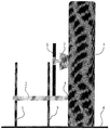
図1は,トレーラの走行方向から見た,音圧センサを調整するための位置決め装置の例示的な実施態様の側面図を示す。複数の音圧センサ(図示せず)はトレーラ(図示せず)の杆状部材に取り付ける。道路の測定表面を走行中に車輪のタイヤ1が発する音圧レベルを測定する間,前記杆状部材はトレーラの走行方向に対して平行に設置される。前記位置決め装置は,路面4に対して平行に平坦な横架材2を設置できるよう高さを調整可能な複数の支柱3に載置した平坦な横架材2を備える。平坦な横架材2の内縁5は,車輪のタイヤ1に隣接しており,平坦な横架材2はホルダ7の垂直杆6に堅固に取り付けられ,車輪のハブの中心に位置決め装置を取り付けるためのホルダ7は,垂直杆6に対して摺動可能に設置される。ホルダ7と垂直杆6との摺動可能な連結部は,係止装置(図示せず)により係止し得る。平坦な横架材2と路面4との間の距離は,前記複数の支柱3により6〜25cmの範囲に調整し得る。
FIG. 1 shows a side view of an exemplary embodiment of a positioning device for adjusting a sound pressure sensor as seen from the direction of travel of a trailer. A plurality of sound pressure sensors (not shown) are attached to a bowl-shaped member of a trailer (not shown). While measuring the sound pressure level generated by the
図2は音圧センサを位置決めするための位置決め装置の例示的な実施態様の平面図を示す。平坦な横架材2の内縁5は車輪のタイヤ1に隣接しており,平坦な横架材2は,音圧センサを載置するための複数のマーク9を有する外縁8を設け,平坦な横架材2上のこれらマーク9から,タイヤ1の最接近部と道路の測定表面4とが接触する部分へ音圧センサを向けるための交点という共有点へ複数のライン10が伸長する。音圧センサを載置するためのマーク9は音圧センサを受容して設定位置に固定するため,通常は凹条である。音圧センサを載置するためのマーク9は通常,車輪及びタイヤ1の軸に対して対称に配置され,15〜25cm,好適には20cmの範囲で均等に互いに離間する。平坦な横架材2は,外縁8に定規ないし目盛り(図示せず)を備え,該定規ないし目盛りを使用して各マーク9と平坦な横架材2の中心との間の距離を読み取るか,或いは平坦な横架材2の外縁8に沿った規定の経路に音圧センサを移動させることが可能となる。音圧センサとして指向性マイクが最も一般的に使用される。
FIG. 2 shows a plan view of an exemplary embodiment of a positioning device for positioning a sound pressure sensor. An inner edge 5 of the flat
操作中,音圧センサを調整するための位置決め装置は以下のように作動する:路面4上に音圧センサが設置されるべき高さを決定する。例えばねじ手段(thread means)を使用して支柱3を所望の高さに応じて持ち上げる。前記例示的な実施態様によると,位置決め装置があらゆる車輪寸法及びタイヤ寸法に適合できるように,位置決め装置は,路面4上の平坦な横架材の高さを6〜25cmに調整することができる。平坦な横架材2を,車輪のタイヤ1に隣接する内縁5と共に設置する。その後,垂直杆6をホルダ7内に移動させ,車輪のハブの中心に位置決め装置を取り付けることが可能となる。ホルダ7が車輪の取り付けハブの中心に取り付けられ,路面4上で平坦な横架材2が支柱3により持ち上がるよう支柱3が設置されると,ホルダ7は垂直杆6で係止され,位置決めの開始が可能となる。蝶着されたホルダ(図示せず)に音圧センサが設置される。これらのホルダの接合は解除されず,音圧センサの最上部を各マーク9内に収容し,センサはライン10の交点に向けて平坦な横架材2上のライン10に沿って向けられ,それにより平坦な横架材2の平面内の音圧センサの軸の垂直投影が各ライン10と一致する。その後,1つの平面内のみに,すなわち音圧センサの軸及び各ライン10により画定された平面内に音圧センサを手動で設置する必要がある。この手動での設置によって,音圧センサはタイヤ1の最接近部と道路の測定表面4との接触点に向けられる。個々の音圧センサを設置した後に,平坦な横架材2及び車輪のハブに取り付けたホルダ7から支柱3を取り外し,それにより,音圧センサのいずれかと不慮に衝突することなくタイヤ1周辺の領域から安全に平坦な横架材2が引き抜かれ得る。
During operation, the positioning device for adjusting the sound pressure sensor operates as follows: Determines the height at which the sound pressure sensor should be installed on the road surface 4. For example, thread means are used to lift the column 3 according to the desired height. According to the exemplary embodiment, the positioning device can adjust the height of the flat horizontal member on the road surface 4 to 6-25 cm so that the positioning device can adapt to any wheel size and tire size. . A flat
本発明の音圧センサを位置決めするための位置決め装置を使用すれば,音圧センサの位置決めに要する時間が大幅に削減され,結果としてこのような位置決めが大幅に正確なものとなる。 If the positioning device for positioning the sound pressure sensor of the present invention is used, the time required for positioning of the sound pressure sensor is greatly reduced, and as a result, such positioning becomes significantly accurate.
本発明は,測定路面を走行中に車輪のタイヤが発する音圧レベルの測定の準備をする際に使用し得る。 The present invention can be used when preparing for the measurement of the sound pressure level generated by the wheel tires while traveling on the measurement road surface.
1.タイヤ
2.平坦な横架材
3.支柱
4.路面
5.(平坦な横架材の)内縁
6.垂直杆
7.ホルダ
8.(平坦な横架材の)外縁
9.マーク
10.ライン
1. tire
2. 2. Flat horizontal member Post 4. 4. Road surface 5. Inner edge (of flat horizontal member) Vertical fence7.
Ten. line
Claims (7)
Applications Claiming Priority (2)
| Application Number | Priority Date | Filing Date | Title |
|---|---|---|---|
| CZ20110826A CZ2011826A3 (en) | 2011-12-15 | 2011-12-15 | Setting device |
| CZPV2011-826 | 2011-12-15 |
Publications (2)
| Publication Number | Publication Date |
|---|---|
| JP2013125030A JP2013125030A (en) | 2013-06-24 |
| JP6164827B2 true JP6164827B2 (en) | 2017-07-19 |
Family
ID=45654760
Family Applications (1)
| Application Number | Title | Priority Date | Filing Date |
|---|---|---|---|
| JP2012267546A Expired - Fee Related JP6164827B2 (en) | 2011-12-15 | 2012-12-06 | Positioning device |
Country Status (4)
| Country | Link |
|---|---|
| US (2) | US20130168513A1 (en) |
| EP (1) | EP2604994B1 (en) |
| JP (1) | JP6164827B2 (en) |
| CZ (1) | CZ2011826A3 (en) |
Families Citing this family (5)
| Publication number | Priority date | Publication date | Assignee | Title |
|---|---|---|---|---|
| CN106441699B (en) * | 2016-08-30 | 2022-05-17 | 重庆长安民生物流股份有限公司 | Automobile tire pressure detection device |
| JP7133458B2 (en) * | 2018-12-17 | 2022-09-08 | Toyo Tire株式会社 | Sound source identification method |
| JP7185565B2 (en) * | 2019-03-07 | 2022-12-07 | Toyo Tire株式会社 | Method for estimating tire test results |
| CN112066210A (en) * | 2020-08-18 | 2020-12-11 | 蔡君亮 | Assembly type building construction noise pollution detection device |
| CN112728309A (en) * | 2020-12-22 | 2021-04-30 | 中国船舶重工集团公司第七0三研究所 | Vibration sensor support for gas turbine |
Family Cites Families (20)
| Publication number | Priority date | Publication date | Assignee | Title |
|---|---|---|---|---|
| US2678559A (en) * | 1951-12-29 | 1954-05-18 | Sperry Prod Inc | Ultrasonic rail test device |
| JPS5961721A (en) * | 1982-10-01 | 1984-04-09 | Bridgestone Corp | Method and apparatus for searching sound source |
| US4723444A (en) * | 1986-09-17 | 1988-02-09 | Jaroslav Hajek | Apparatus for determining side-slip characteristics of a moving vehicle |
| US6799470B2 (en) * | 1987-02-04 | 2004-10-05 | Kabushiki Kaisha Haradakuni | Lateral force-measuring device for a wheel, lateral force-measuring method, and vehicle-inspecting system having the device |
| JPH06174543A (en) * | 1992-12-03 | 1994-06-24 | Toyota Motor Corp | Detecting apparatus for road surface condition |
| JPH0755649A (en) * | 1993-08-23 | 1995-03-03 | Bridgestone Corp | Method of testing noise of tire |
| US5515726A (en) * | 1994-12-27 | 1996-05-14 | Chrysler Corporation | Vehicle wheel cover noise testing machine |
| US5561244A (en) * | 1995-03-10 | 1996-10-01 | Bridgestone/Firestone, Inc. | Method and apparatus for measuring the dynamic camber of vehicle tires |
| JP3473158B2 (en) * | 1995-03-22 | 2003-12-02 | 住友電気工業株式会社 | Road surface condition detection device |
| JPH0954020A (en) * | 1995-08-10 | 1997-02-25 | Sumitomo Electric Ind Ltd | Road condition detecting device |
| JP2002243535A (en) * | 2001-02-20 | 2002-08-28 | Omron Corp | Road surface condition detecting device |
| JP3874705B2 (en) * | 2002-07-26 | 2007-01-31 | ニッケン株式会社 | Vehicle running sound tester |
| US6739186B1 (en) * | 2002-08-14 | 2004-05-25 | The Goodyear Tire & Rubber Company | Tire and rim assembly centering method |
| US6981419B1 (en) * | 2003-05-15 | 2006-01-03 | Hay D Robert | Portable direct sensor attachment system |
| FR2866114B1 (en) * | 2004-02-11 | 2006-05-05 | Airbus France | MOBILE TEST BENCH FOR TIRES, AND METHOD FOR IMPLEMENTING SUCH A TEST BENCH |
| DE102005012702B3 (en) * | 2005-03-11 | 2006-09-14 | Forschungsinstitut für Kraftfahrwesen und Fahrzeugmotoren Stuttgart (FKFS) | Method of determining a noise component caused by a wheel of a vehicle rolling on a road surface from all the noise in the vehicle |
| US7775096B2 (en) * | 2008-10-15 | 2010-08-17 | The Goodyear Tire & Rubber Company | Wheel based sensor assembly |
| CN101762319B (en) * | 2008-12-24 | 2011-11-09 | 交通部公路科学研究院 | Balance weight tyre and road noise detecting trailer |
| EP2211161B1 (en) * | 2009-01-22 | 2012-07-11 | Snap-on Equipment Srl a unico socio | Wheel diagnosis system |
| US8113040B2 (en) * | 2009-07-13 | 2012-02-14 | K-Line Industries, Inc. | Tire runout gauge |
-
2011
- 2011-12-15 CZ CZ20110826A patent/CZ2011826A3/en unknown
-
2012
- 2012-01-24 EP EP12000426.2A patent/EP2604994B1/en not_active Not-in-force
- 2012-12-06 JP JP2012267546A patent/JP6164827B2/en not_active Expired - Fee Related
- 2012-12-13 US US13/713,580 patent/US20130168513A1/en not_active Abandoned
-
2014
- 2014-06-05 US US14/296,881 patent/US20150114147A1/en not_active Abandoned
Also Published As
| Publication number | Publication date |
|---|---|
| EP2604994A2 (en) | 2013-06-19 |
| EP2604994A3 (en) | 2016-02-17 |
| US20130168513A1 (en) | 2013-07-04 |
| JP2013125030A (en) | 2013-06-24 |
| US20150114147A1 (en) | 2015-04-30 |
| CZ2011826A3 (en) | 2013-06-26 |
| EP2604994B1 (en) | 2017-01-04 |
Similar Documents
| Publication | Publication Date | Title |
|---|---|---|
| JP6164827B2 (en) | Positioning device | |
| US8020307B2 (en) | Alignment system and method for vehicle-mounted devices | |
| CN104534998B (en) | A kind of automobile basic parameter measurement apparatus and its measuring method | |
| JP6946237B2 (en) | Marker installation system and method | |
| US20210278856A1 (en) | System and method for determining a position and/or orientation of a swap body in relation to a vehicle | |
| US4363175A (en) | Truck wheel clamp | |
| CN104048589A (en) | Device for measuring vertical displacement of automotive suspension | |
| JPS63172938A (en) | Wheel aligner for car | |
| US11835332B2 (en) | Device and method for detecting the steering wheel position, the steering wheel angle and the inclination of the steering wheel of a vehicle | |
| CN107678037B (en) | Automobile deviation measuring device and measuring method thereof | |
| CN105403160A (en) | Automobile size measuring device and automobile size measuring method | |
| US4271599A (en) | Wheel camber and castor measurement apparatus | |
| CN102175114B (en) | Wheel guard plate measurement device and measurement method | |
| CN210426388U (en) | Racing car wheel inclination angle and toe angle measuring device | |
| CN114199113A (en) | Four-wheel locating rack | |
| CN212963168U (en) | Four-wheel positioning frame | |
| CN211010673U (en) | Fixing support for noise test microphone in vehicle | |
| US9739589B2 (en) | Vehicle wheel alignment device | |
| CN208818181U (en) | The cubing of vehicle | |
| CN205593505U (en) | Motor vehicle track measuring device | |
| JP2018132502A (en) | Tire testing method | |
| CZ24793U1 (en) | Adapter device | |
| CN218566355U (en) | Auxiliary device is adjusted to trailer axletree | |
| KR102589846B1 (en) | Tire stiffness measuring device | |
| KR102545131B1 (en) | Tire rotation angle measurement device |
Legal Events
| Date | Code | Title | Description |
|---|---|---|---|
| A621 | Written request for application examination |
Free format text: JAPANESE INTERMEDIATE CODE: A621 Effective date: 20151204 |
|
| A977 | Report on retrieval |
Free format text: JAPANESE INTERMEDIATE CODE: A971007 Effective date: 20161007 |
|
| A131 | Notification of reasons for refusal |
Free format text: JAPANESE INTERMEDIATE CODE: A131 Effective date: 20161013 |
|
| A521 | Request for written amendment filed |
Free format text: JAPANESE INTERMEDIATE CODE: A523 Effective date: 20161220 |
|
| RD02 | Notification of acceptance of power of attorney |
Free format text: JAPANESE INTERMEDIATE CODE: A7422 Effective date: 20161220 |
|
| TRDD | Decision of grant or rejection written | ||
| A01 | Written decision to grant a patent or to grant a registration (utility model) |
Free format text: JAPANESE INTERMEDIATE CODE: A01 Effective date: 20170525 |
|
| A61 | First payment of annual fees (during grant procedure) |
Free format text: JAPANESE INTERMEDIATE CODE: A61 Effective date: 20170620 |
|
| R150 | Certificate of patent or registration of utility model |
Ref document number: 6164827 Country of ref document: JP Free format text: JAPANESE INTERMEDIATE CODE: R150 |
|
| R250 | Receipt of annual fees |
Free format text: JAPANESE INTERMEDIATE CODE: R250 |
|
| LAPS | Cancellation because of no payment of annual fees |