EP2604967B1 - Airburst simulation system and method of simulation for airburst - Google Patents
Airburst simulation system and method of simulation for airburst Download PDFInfo
- Publication number
- EP2604967B1 EP2604967B1 EP12196085.0A EP12196085A EP2604967B1 EP 2604967 B1 EP2604967 B1 EP 2604967B1 EP 12196085 A EP12196085 A EP 12196085A EP 2604967 B1 EP2604967 B1 EP 2604967B1
- Authority
- EP
- European Patent Office
- Prior art keywords
- laser
- airburst
- laser beam
- target
- unit
- Prior art date
- Legal status (The legal status is an assumption and is not a legal conclusion. Google has not performed a legal analysis and makes no representation as to the accuracy of the status listed.)
- Active
Links
Images




Classifications
-
- F—MECHANICAL ENGINEERING; LIGHTING; HEATING; WEAPONS; BLASTING
- F41—WEAPONS
- F41G—WEAPON SIGHTS; AIMING
- F41G1/00—Sighting devices
- F41G1/32—Night sights, e.g. luminescent
- F41G1/34—Night sights, e.g. luminescent combined with light source, e.g. spot light
-
- F—MECHANICAL ENGINEERING; LIGHTING; HEATING; WEAPONS; BLASTING
- F41—WEAPONS
- F41G—WEAPON SIGHTS; AIMING
- F41G3/00—Aiming or laying means
- F41G3/26—Teaching or practice apparatus for gun-aiming or gun-laying
- F41G3/2616—Teaching or practice apparatus for gun-aiming or gun-laying using a light emitting device
- F41G3/2622—Teaching or practice apparatus for gun-aiming or gun-laying using a light emitting device for simulating the firing of a gun or the trajectory of a projectile
- F41G3/2655—Teaching or practice apparatus for gun-aiming or gun-laying using a light emitting device for simulating the firing of a gun or the trajectory of a projectile in which the light beam is sent from the weapon to the target
-
- F—MECHANICAL ENGINEERING; LIGHTING; HEATING; WEAPONS; BLASTING
- F41—WEAPONS
- F41A—FUNCTIONAL FEATURES OR DETAILS COMMON TO BOTH SMALLARMS AND ORDNANCE, e.g. CANNONS; MOUNTINGS FOR SMALLARMS OR ORDNANCE
- F41A33/00—Adaptations for training; Gun simulators
- F41A33/02—Light- or radiation-emitting guns ; Light- or radiation-sensitive guns; Cartridges carrying light emitting sources, e.g. laser
-
- F—MECHANICAL ENGINEERING; LIGHTING; HEATING; WEAPONS; BLASTING
- F41—WEAPONS
- F41G—WEAPON SIGHTS; AIMING
- F41G3/00—Aiming or laying means
- F41G3/26—Teaching or practice apparatus for gun-aiming or gun-laying
-
- F—MECHANICAL ENGINEERING; LIGHTING; HEATING; WEAPONS; BLASTING
- F41—WEAPONS
- F41G—WEAPON SIGHTS; AIMING
- F41G3/00—Aiming or laying means
- F41G3/26—Teaching or practice apparatus for gun-aiming or gun-laying
- F41G3/2616—Teaching or practice apparatus for gun-aiming or gun-laying using a light emitting device
- F41G3/2622—Teaching or practice apparatus for gun-aiming or gun-laying using a light emitting device for simulating the firing of a gun or the trajectory of a projectile
- F41G3/2683—Teaching or practice apparatus for gun-aiming or gun-laying using a light emitting device for simulating the firing of a gun or the trajectory of a projectile with reflection of the beam on the target back to the weapon
- F41G3/2688—Teaching or practice apparatus for gun-aiming or gun-laying using a light emitting device for simulating the firing of a gun or the trajectory of a projectile with reflection of the beam on the target back to the weapon using target range measurement, e.g. with a laser rangefinder
-
- F—MECHANICAL ENGINEERING; LIGHTING; HEATING; WEAPONS; BLASTING
- F41—WEAPONS
- F41J—TARGETS; TARGET RANGES; BULLET CATCHERS
- F41J5/00—Target indicating systems; Target-hit or score detecting systems
- F41J5/02—Photo-electric hit-detector systems
-
- F—MECHANICAL ENGINEERING; LIGHTING; HEATING; WEAPONS; BLASTING
- F42—AMMUNITION; BLASTING
- F42B—EXPLOSIVE CHARGES, e.g. FOR BLASTING, FIREWORKS, AMMUNITION
- F42B12/00—Projectiles, missiles or mines characterised by the warhead, the intended effect, or the material
- F42B12/02—Projectiles, missiles or mines characterised by the warhead, the intended effect, or the material characterised by the warhead or the intended effect
- F42B12/36—Projectiles, missiles or mines characterised by the warhead, the intended effect, or the material characterised by the warhead or the intended effect for dispensing materials; for producing chemical or physical reaction; for signalling ; for transmitting information
- F42B12/56—Projectiles, missiles or mines characterised by the warhead, the intended effect, or the material characterised by the warhead or the intended effect for dispensing materials; for producing chemical or physical reaction; for signalling ; for transmitting information for dispensing discrete solid bodies
- F42B12/58—Cluster or cargo ammunition, i.e. projectiles containing one or more submissiles
-
- F—MECHANICAL ENGINEERING; LIGHTING; HEATING; WEAPONS; BLASTING
- F42—AMMUNITION; BLASTING
- F42B—EXPLOSIVE CHARGES, e.g. FOR BLASTING, FIREWORKS, AMMUNITION
- F42B8/00—Practice or training ammunition
- F42B8/12—Projectiles or missiles
- F42B8/18—Rifle grenades
-
- F—MECHANICAL ENGINEERING; LIGHTING; HEATING; WEAPONS; BLASTING
- F41—WEAPONS
- F41A—FUNCTIONAL FEATURES OR DETAILS COMMON TO BOTH SMALLARMS AND ORDNANCE, e.g. CANNONS; MOUNTINGS FOR SMALLARMS OR ORDNANCE
- F41A19/00—Firing or trigger mechanisms; Cocking mechanisms
- F41A19/06—Mechanical firing mechanisms, e.g. counterrecoil firing, recoil actuated firing mechanisms
- F41A19/42—Mechanical firing mechanisms, e.g. counterrecoil firing, recoil actuated firing mechanisms having at least one hammer
Definitions
- This specification relates to an airburst simulation system, an airburst simulation method, and a simulation apparatus having a dual barrel used therefor.
- the present disclosure relates to an airburst simulation apparatus for simulating airburst of airburst ammunitions.
- a Multiple Integrated Laser Engagement System (MILES) as virtual engagement equipment is used world-widely for carrying out a combat training similar to an actual combat.
- the MILES system is an equipment which has been developed for providing realistic combat experience using properties of laser beams, such as straight propagation, data transfer, harmlessness to human bodies and the like.
- the MILES system includes a laser emitting unit (or laser firing unit), and a laser detecting unit.
- the laser detecting unit detects (senses) whether or not laser beam emitted from the laser emitting unit hits the target.
- a personal firearm having a dual barrel which allows for selective firing (shooting) of a small caliber bullet and a large caliber airburst ammunition.
- the MILES system which senses laser beam reaching the target has a problem in that an airburst mode, in which an airburst ammunition is fired to a hidden target, is unable to be simulated.
- an aspect of the detailed description is to provide a simulation of an airburst mode using a laser.
- an airburst simulation system including a laser emitting unit, a laser detecting unit and a determining unit.
- the laser emitting unit may emit laser beam to an airburst aiming position, preset above a target hidden behind an obstacle, such that a warhead is airbursted to shoot the target.
- the laser detecting unit may be mounted onto the target to detect an arrival of the laser beam above the target.
- the determining unit may measure a distance between the airburst aiming position and an arrival position of the laser detected by the laser detecting unit, and determine whether or not the target has been shot based on the distance.
- the laser emitting unit may include a body and a laser emitter.
- the body may have a trigger.
- the laser emitter may be installed in the body to emit laser beam by pulling the trigger.
- the laser emitting unit may include a firing pin protruded by the trigger to press a simulated ammunition, and a pressure sensor to sense pressure applied onto the simulated ammunition, and convert the sensed pressure into a signal to transfer to the laser emitting unit.
- the laser emitting unit may further include a firing noise generator to generate noise upon emitting the laser beam.
- the laser emitting unit may include a blank cartridge fired by the trigger, and a firing impact detector to detect the firing of the blank cartridge.
- the laser emitting unit may include a Global Positioning System (GPS), and an electronic compass.
- GPS Global Positioning System
- electronic compass an electronic compass
- the laser detecting unit may include first and second cameras disposed with being spaced apart from each other to photograph the laser beam, respectively, at the spaced positions, and a posture sensing unit to measure respective angles that the first and second cameras face the laser.
- the determining unit may measure the distance between the airburst aiming position and the arrival position of the detected laser, to determine whether or not the target has been shot based on the measured distance and a preset reference distance.
- the determining unit may include a display unit to output at least one of an image and a sound to indicate whether or not the target has been shot.
- the determining unit may determine which laser beam of the plurality of laser beams has shot the target, by comparison between a time point of sensing the arrival of the laser beam and a time point of emitting the laser beam, comparison between coordinates of a position of the target and coordinates of the airburst aiming position, and comparison between a directional vector of the emitted laser beam and a directional vector of the laser beam detected by the laser detecting unit.
- the available number of laser emission by the laser emitting unit may be limited to a preset number of times, and the determining unit may determine a laser beam which is emitted after exceeding the preset number of times to be invalid.
- a simulation method for an airburst including emitting laser beam to an airburst aiming position, preset above a target hidden behind an obstacle, such that a warhead is airbursted to shoot the target, detecting the laser beam arriving above the target, and measuring a distance between the airburst aiming position and an arrival position of the laser beam, and determining whether or not the target has been shot based on the distance.
- the step of emitting the laser beam to the airburst aiming position, preset above the target hidden behind an obstacle, such that the warhead is airbursted to shoot the target may include applying pressure to a simulated ammunition by pulling a trigger, generating a signal by sensing the pressure applied to the simulated ammunition, and emitting the laser beam in response to the signal.
- the step of emitting the laser beam to the airburst aiming position may include measuring a distance from a position of emitting the laser beam to the obstacle so as to estimate a distance up to the target.
- the airburst simulation system may include a laser emitting unit and a laser detecting unit. A soldier who carries out an airburst simulation test may wear at least one of the laser emitting unit and the laser detecting unit.
- the airburst simulation system may further include a determining unit to determine information obtained by the laser emitting unit and the laser detecting unit.
- the laser emitting unit, the laser detecting unit and the determining unit will be described in detail.
- the laser emitting unit may be implemented as an airburst simulation apparatus.
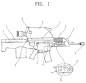
- FIG. 1 is a side view of an airburst simulation apparatus having a laser emitting unit.
- FIG. 2 is a configuration view of the laser emitter of FIG. 1 .
- FIGS. 3A to 3C are conceptual views showing an operation of a pressure sensor which is cooperative with a simulated ammunition interface (or a dummy ammunition interface) of FIG. 2 .
- FIG. 4 is a flowchart showing sequential operation steps of a firing simulation system for an airburst using the airburst simulation apparatus.
- FIG. 5 is a side conceptual view showing an engagement simulation method for an airburst using the airburst simulation apparatus.
- FIG. 6 is a top conceptual view showing the engagement simulation method for the airburst using the airburst simulation apparatus.
- the airburst simulation apparatus may be implemented as a personal firearm having a dual barrel 1.
- the personal firearm having a dual barrel 1 may include an airburst ammunition barrel 5, a bullet barrel 4, a fire control system 3, a trigger 11, a laser emitting device 18, and a rifle 2.
- An obstacle behind which a target is hidden may be detected through a scope (not shown) of the fire control system 3, and a range up to the obstacle may be measured by operating a laser emitting button 12, which is cooperative with a laser range finder (not shown) disposed within the fire control system 3.
- a distance up to the target may be adjusted using range varying buttons 13 and 14, by taking a thickness of the obstacle into account.
- the personal firearm having a dual barrel 1 may select a bullet and an airburst ammunition.
- a fuse mode setting button 15 may be used to select one of airburst, point detonation or point delayed detonation as the fuse mode.
- the point detonation indicates that an explosive shell (bombshell, explosive bullet) is detonated (exploded) by impact at the moment when a target arrives, and the point delayed detonation indicates that the explosive shell penetrates through an obstacle and is detonated after a preset time elapses when a target is hidden behind an obstacle.
- the airburst indicates that the explosive shell is detonated above a target.
- the airburst simulation apparatus may further include a laser emitter 7, a fire control system interface wire 8, an airburst simulated ammunition (or airburst dummy ammunition) 9, and a simulated ammunition interface wire 10. Also, the airburst simulation apparatus may include a fire control system interface 25, and a simulated ammunition interface 26, and further include at least one of a firing (shooting) noise generator 29, and a firing impact detector 28. Also, a power supply 27 for supplying power to the laser emitter 7 may be installed in the airburst simulation apparatus.
- the laser emitter 7 may be installed on the personal firearm having a dual barrel 1.
- a laser (or laser beam) may be emitted (fired, shot) instead of the airburst ammunition.
- the laser emitter 7 may preferably be installed near an airburst ammunition barrel (air explosive bomb barrel, air explosive shell barrel, airburst bomb barrel). That is, the laser emitter 7 may be arranged such that laser beam is emitted in the same direction as the airburst ammunition barrel 5 firing the airburst ammunition.
- the laser emitter 7 may emit laser beam by detecting pressure applied onto the airburst simulated ammunition 9 as the trigger 11 is pulled. Thus, whether or not the laser beam has been emitted may be determined based on the airburst simulated ammunition 9.
- a hammer 17 connected to the trigger 11 may be released from a rotation-restricted state. Accordingly, the hammer 17 may rotate to hit a firing pin 16. The firing pin 16 may thus move forward to apply pressure to a pressure sensor of the simulated ammunition 9.
- the pressure sensor may generate a signal in response to the pressure, and the signal may be transmitted to the laser emitter 7 via the simulated ammunition interface wire 10.
- the signal may be transferred to the laser emitting device 18 via a code converter 24, accordingly, the laser emitting device 18 may emit the laser beam.
- the simulated ammunition 9 may be replaced with a blank cartridge.
- the firing impact detector 28 may detect an impact when the blank cartridge is fired, and accordingly laser beam may be emitted.
- the airburst simulation apparatus may further include a Global Positioning System (GPS) 20, an electronic compass 21, and a wireless transceiver 22.
- the electronic compass 21 may include a 2-axis magnetic sensor, a tilt sensor, or a 3-axis magnetic sensor. Therefore, the electronic compass 21 may measure an azimuth ( ⁇ ) as a rotational angle from the true north of a laser optic axis, and an elevation ( ⁇ ) as a tilt angle from the ground.
- the GPS 20 may be replaced with an indoor location tracking unit 23.
- the indoor location tracking unit 23 may include at least one of various sensors, for example, a gyro sensor, an acceleration sensor, an ultrasonic sensor and a radio frequency (RF) sensor.
- the indoor location tracking unit 23 may thus track a moving path of a soldier using the sensor. That is, when the soldier is located within a building, a sensor may be installed at a specific location, of which GPS coordinates are aware, within the building. Accordingly, when the soldier passes the specific location, the sensor may sense the soldier's location. This may allow for compensation for the soldier's 3D GPS coordinates.
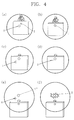
- FIG. 4 is a flowchart showing sequential operation steps of a firing simulation system for an airburst using the airburst simulation apparatus.
- a target is hidden behind an obstacle, for example, behind a wall or inside a trench.
- a laser aiming marker A may match a laser aiming position T, namely, the obstacle where the target is hidden.
- the laser range finder may operate to measure a distance up to the obstacle, and control (adjust, compensate for) a range using the range varying buttons 13 and 14, taking into account a spaced distance between the target and the obstacle behind the obstacle and a thickness of the obstacle.
- an optic axis of the laser beam emitted from the laser range finder may be arranged to match an optic axis of laser beam fired from the laser emitter 7.
- Range information, a type of ammunition and a fuse mode may be transmitted to the laser emitter 7 via the fire control system interface wire 8, which is connected to an external connection hole 6 located on a right surface of the fire control system 3.
- an aiming point marker R based on the trajectory calculation by the fire control system 3, may be displayed on the scope of the fire control system 3.
- the aiming point marker R is a value to which a trajectory in a parabolic form by the gravity is reflected. Therefore, upon emitting the laser beam with the straight propagation property, the laser aiming marker A may be used for firing. The laser beam may thusly be emitted toward the laser aiming marker A.
- a detecting unit for detecting the emitted laser beam and a determining unit for determining whether or not a target has been shot The detecting unit and the determining unit may be implemented by the laser detector 30.
- FIG. 7 is a configuration view of a laser detector
- FIG. 8 is a conceptual view of a helmet having the laser detector.
- the laser detector 30 may include first and second cameras 33 and 34, a GPS 37, a camera posture sensing unit 35, a display unit 41, an alarm generating unit 42, a power supply 38 and a detection controller 36.
- the laser detector 30 may be mounted, for example, to a helmet 31 of a target.
- the laser detector 30 may preferably be arranged on a top of the helmet 31 and in a circumferential direction of the helmet 31 so as to detect an overall region around the helmet 31.
- the laser detector 30 may be installed in a combat uniform of a target, and the installation position may not be limited to preset position.
- Each of the first and second cameras 33 and 34 may have, if necessary, an infrared filter for sensing laser beam which passes over the laser detector 30.
- the first and second cameras 33 and 34 may be spaced apart from each other to photograph (take) the laser beam into stereo images. Therefore, 3D relative coordinates of the laser beam may be calculated based on a distance up to the photographed laser beam and positions that the first and second cameras 33 and 34 are mounted on the target, respectively.
- the camera posture sensing unit 35 may be installed.
- the camera posture sensing unit 35 may include a gyro sensor.
- the GPS 37 may allow for recognizing a current position of the laser detector 30 using electric waves transmitted from a satellite. That is, the GPS 37 may allow for identifying a position of the target, to measure a distance between the actual position of the target and the airburst aiming position. Accordingly, whether or not the target is to be shot by the laser beam may be determined on the basis as to whether the airburst aiming position is close to the actual position of the target.
- the actual position of the target obtained by use of the GPS 37 may be compared with the airburst aiming position to determine whether the airburst aiming position has precisely been set, and a distance between the airburst aiming position and a laser arrival position detected by the laser detector 30 after the laser beam arrives may be calculated to determine whether or not the calculated distance is within a preset distance. Such determinations may allow for determining whether or not the target has been shot.
- the display unit 41 may include an display window (not shown) which exhibits whether or not the target has been shot. This is to show whether or not a soldier who is carrying out a simulated engagement has been shot by another soldier.
- the alarm generating unit 42 may generate an alarm sound to allow the successful firing to be identified from far away.
- the detection controller 36 may control operations of the first and second cameras 33 and 34, the camera posture sensing unit 35, the GPS 37 and the display unit 41.
- the laser beam within the images captured by the first and second cameras 33 and 34 may be displayed with a segment.
- an indoor location tracking unit 39 may replace the GPS 37.
- the indoor location tracking unit 39 may be implemented substantially in the same manner as the indoor position tracking unit 23 installed in the laser emitter 7. Therefore, the implementation method of the indoor position tracking unit 39 may be understood by the description of indoor position tracking unit 23 in the laser emitter 7, so detailed description thereof will be omitted.
- the power supply 38 may supply power necessary to drive the laser detector 30.
- GPS 20, 37 and the indoor position tracking unit 23, 39 may be installed according to whether or not a region is tracked by GPS. Also, the GPS 20, 37, the indoor location tracking unit 23, 39, the power supply 27, 38 and the wireless transceiver 22, 40 may be integrated into a common module, to be installed in the laser emitter 7 and the laser detector 30.
- P t ( X t , Y t , Z t ) of airburst aiming position to which the soldiers have shot the laser beams.
- the preset distance (L) may be set by taking into account an error between the GPS coordinates of the target and the GPS coordinates of the soldier and a casualty radius of the airburst ammunition.
- the wireless transceiver 40 of the laser detector 30 may receive the results and exhibit the results on the display unit 41. Also, the alarm generating unit 42 may generate the alarm sound.
- the detection controller 36 of the laser detector 30 may record the number of firing carried out by each soldier. For example, when a solider exceeds a preset number of firing, the soldier may be unable to fire (emit) a laser beam any more even if he pulls the trigger 11.
- the training control center may also check the number of firing carried out by each soldier. Accordingly, laser beams, which have been detected by the laser detector 30 as exceeding the preset number of firing, may be determined as not hit.
- an airburst by which a target hidden behind an obstacle is shot, may be simulated by using the airburst simulation apparatus.
- a GPS, an electronic compass or an indoor location tracking unit, an airburst aiming position and a detection position of a laser beam may be precisely recognized, thereby determining whether or not the target has been shot.
- noise generating unit or a blank cartridge may allow the simulation to be similar to an actual situation.
Landscapes
- Engineering & Computer Science (AREA)
- General Engineering & Computer Science (AREA)
- Radar, Positioning & Navigation (AREA)
- Physics & Mathematics (AREA)
- Optics & Photonics (AREA)
- Chemical & Material Sciences (AREA)
- Combustion & Propulsion (AREA)
- Aiming, Guidance, Guns With A Light Source, Armor, Camouflage, And Targets (AREA)
- Radar Systems Or Details Thereof (AREA)
Description
- This specification relates to an airburst simulation system, an airburst simulation method, and a simulation apparatus having a dual barrel used therefor.
- The present disclosure relates to an airburst simulation apparatus for simulating airburst of airburst ammunitions. A Multiple Integrated Laser Engagement System (MILES) as virtual engagement equipment is used world-widely for carrying out a combat training similar to an actual combat. The MILES system is an equipment which has been developed for providing realistic combat experience using properties of laser beams, such as straight propagation, data transfer, harmlessness to human bodies and the like. The MILES system includes a laser emitting unit (or laser firing unit), and a laser detecting unit. The laser detecting unit detects (senses) whether or not laser beam emitted from the laser emitting unit hits the target.
- In recent time, a personal firearm having a dual barrel which allows for selective firing (shooting) of a small caliber bullet and a large caliber airburst ammunition. Here, the MILES system which senses laser beam reaching the target has a problem in that an airburst mode, in which an airburst ammunition is fired to a hidden target, is unable to be simulated.
- An airburst simulation system is disclosed in
DE 10 2005 055099A1 - Therefore, an aspect of the detailed description is to provide a simulation of an airburst mode using a laser.
- To achieve these and other advantages and in accordance with the purpose of this specification, as embodied and broadly described herein, there is provided an airburst simulation system including a laser emitting unit, a laser detecting unit and a determining unit. The laser emitting unit may emit laser beam to an airburst aiming position, preset above a target hidden behind an obstacle, such that a warhead is airbursted to shoot the target. The laser detecting unit may be mounted onto the target to detect an arrival of the laser beam above the target. The determining unit may measure a distance between the airburst aiming position and an arrival position of the laser detected by the laser detecting unit, and determine whether or not the target has been shot based on the distance.
- In one aspect of the present disclosure, the laser emitting unit may include a body and a laser emitter. The body may have a trigger. The laser emitter may be installed in the body to emit laser beam by pulling the trigger.
- In one aspect of the present disclosure, the laser emitting unit may include a firing pin protruded by the trigger to press a simulated ammunition, and a pressure sensor to sense pressure applied onto the simulated ammunition, and convert the sensed pressure into a signal to transfer to the laser emitting unit.
- In one aspect of the present disclosure, the laser emitting unit may further include a firing noise generator to generate noise upon emitting the laser beam.
- In one aspect of the present disclosure, the laser emitting unit may include a blank cartridge fired by the trigger, and a firing impact detector to detect the firing of the blank cartridge.
- In one aspect of the present disclosure, the laser emitting unit may include a Global Positioning System (GPS), and an electronic compass.
- In one aspect of the present disclosure, the laser detecting unit may include first and second cameras disposed with being spaced apart from each other to photograph the laser beam, respectively, at the spaced positions, and a posture sensing unit to measure respective angles that the first and second cameras face the laser.
- In one aspect of the present disclosure, the determining unit may measure the distance between the airburst aiming position and the arrival position of the detected laser, to determine whether or not the target has been shot based on the measured distance and a preset reference distance.
- In one aspect of the present disclosure, the determining unit may include a display unit to output at least one of an image and a sound to indicate whether or not the target has been shot.
- In one aspect of the present disclosure, when the laser emitting unit emits a plurality of laser beams, the determining unit may determine which laser beam of the plurality of laser beams has shot the target, by comparison between a time point of sensing the arrival of the laser beam and a time point of emitting the laser beam, comparison between coordinates of a position of the target and coordinates of the airburst aiming position, and comparison between a directional vector of the emitted laser beam and a directional vector of the laser beam detected by the laser detecting unit.
- In one aspect of the present disclosure, the available number of laser emission by the laser emitting unit may be limited to a preset number of times, and the determining unit may determine a laser beam which is emitted after exceeding the preset number of times to be invalid.
- To achieve these and other advantages and in accordance with the purpose of this specification, as embodied and broadly described herein, there is provided a simulation method for an airburst including emitting laser beam to an airburst aiming position, preset above a target hidden behind an obstacle, such that a warhead is airbursted to shoot the target, detecting the laser beam arriving above the target, and measuring a distance between the airburst aiming position and an arrival position of the laser beam, and determining whether or not the target has been shot based on the distance.
- In one aspect of the present disclosure, the step of emitting the laser beam to the airburst aiming position, preset above the target hidden behind an obstacle, such that the warhead is airbursted to shoot the target may include applying pressure to a simulated ammunition by pulling a trigger, generating a signal by sensing the pressure applied to the simulated ammunition, and emitting the laser beam in response to the signal.
- In one aspect of the present disclosure, the step of emitting the laser beam to the airburst aiming position may include measuring a distance from a position of emitting the laser beam to the obstacle so as to estimate a distance up to the target.
- Further scope of applicability of the present application will become more apparent from the detailed description given hereinafter. However, it should be understood that the detailed description and specific examples, while indicating preferred embodiments of the invention, are given by way of illustration only, since various changes and modifications within the scope of the invention will become apparent to those skilled in the art from the detailed description.
- The accompanying drawings, which are included to provide a further understanding of the invention and are incorporated in and constitute a part of this specification, illustrate exemplary embodiments and together with the description serve to explain the principles of the invention.
- In the drawings:
-
FIG. 1 is a side view of an airburst simulation apparatus having a laser emitter; -
FIG. 2 is a configuration view of the laser emitter ofFIG. 1 ; -
FIGS. 3A to 3C are conceptual views showing an operation of a pressure sensor which is cooperative with a simulated ammunition interface (or a dummy ammunition interface) ofFIG. 2 ; -
FIG. 4 is a flowchart showing sequential operation steps of a firing simulation system for an airburst using the airburst simulation apparatus; -
FIG. 5 is a side conceptual view showing an engagement simulation method for an airburst using the airburst simulation apparatus; -
FIG. 6 is a top conceptual view showing the engagement simulation method for the airburst using the airburst simulation apparatus; -
FIG. 7 is a configuration view of a laser detector; and -
FIG. 8 is a conceptual view of a helmet having the laser detector. - Description will now be given in detail of an airburst simulation system and an airburst simulation method according to the exemplary embodiments, with reference to the accompanying drawings. For the sake of brief description with reference to the drawings, the same or equivalent components will be provided with the same reference numbers, and description thereof will not be repeated. A singular representation may include a plural representation as far as it represents a definitely different meaning from the context.
- The airburst simulation system may include a laser emitting unit and a laser detecting unit. A soldier who carries out an airburst simulation test may wear at least one of the laser emitting unit and the laser detecting unit. The airburst simulation system may further include a determining unit to determine information obtained by the laser emitting unit and the laser detecting unit. Hereinafter, the laser emitting unit, the laser detecting unit and the determining unit will be described in detail.
- The laser emitting unit may be implemented as an airburst simulation apparatus.
-
FIG. 1 is a side view of an airburst simulation apparatus having a laser emitting unit.FIG. 2 is a configuration view of the laser emitter ofFIG. 1 .FIGS. 3A to 3C are conceptual views showing an operation of a pressure sensor which is cooperative with a simulated ammunition interface (or a dummy ammunition interface) ofFIG. 2 .FIG. 4 is a flowchart showing sequential operation steps of a firing simulation system for an airburst using the airburst simulation apparatus.FIG. 5 is a side conceptual view showing an engagement simulation method for an airburst using the airburst simulation apparatus.FIG. 6 is a top conceptual view showing the engagement simulation method for the airburst using the airburst simulation apparatus. - Referring to
FIG. 1 , the airburst simulation apparatus may be implemented as a personal firearm having adual barrel 1. The personal firearm having adual barrel 1 may include anairburst ammunition barrel 5, a bullet barrel 4, afire control system 3, atrigger 11, alaser emitting device 18, and arifle 2. - An obstacle behind which a target is hidden may be detected through a scope (not shown) of the
fire control system 3, and a range up to the obstacle may be measured by operating alaser emitting button 12, which is cooperative with a laser range finder (not shown) disposed within thefire control system 3. A distance up to the target may be adjusted usingrange varying buttons 13 and 14, by taking a thickness of the obstacle into account. - The personal firearm having a
dual barrel 1 may select a bullet and an airburst ammunition. For example, when the airburst ammunition is selected, a fusemode setting button 15 may be used to select one of airburst, point detonation or point delayed detonation as the fuse mode. The point detonation indicates that an explosive shell (bombshell, explosive bullet) is detonated (exploded) by impact at the moment when a target arrives, and the point delayed detonation indicates that the explosive shell penetrates through an obstacle and is detonated after a preset time elapses when a target is hidden behind an obstacle. The airburst indicates that the explosive shell is detonated above a target. - The airburst simulation apparatus may further include a
laser emitter 7, a fire controlsystem interface wire 8, an airburst simulated ammunition (or airburst dummy ammunition) 9, and a simulatedammunition interface wire 10. Also, the airburst simulation apparatus may include a firecontrol system interface 25, and asimulated ammunition interface 26, and further include at least one of a firing (shooting)noise generator 29, and afiring impact detector 28. Also, apower supply 27 for supplying power to thelaser emitter 7 may be installed in the airburst simulation apparatus. - Referring to
FIG. 1 , thelaser emitter 7 may be installed on the personal firearm having adual barrel 1. A laser (or laser beam) may be emitted (fired, shot) instead of the airburst ammunition. Hence, thelaser emitter 7 may preferably be installed near an airburst ammunition barrel (air explosive bomb barrel, air explosive shell barrel, airburst bomb barrel). That is, thelaser emitter 7 may be arranged such that laser beam is emitted in the same direction as theairburst ammunition barrel 5 firing the airburst ammunition. - The
laser emitter 7 may emit laser beam by detecting pressure applied onto the airburst simulatedammunition 9 as thetrigger 11 is pulled. Thus, whether or not the laser beam has been emitted may be determined based on the airburst simulatedammunition 9. - Referring to
FIG. 1 andFIGS. 3A to 3C , upon pulling thetrigger 11, ahammer 17 connected to thetrigger 11 may be released from a rotation-restricted state. Accordingly, thehammer 17 may rotate to hit afiring pin 16. Thefiring pin 16 may thus move forward to apply pressure to a pressure sensor of thesimulated ammunition 9. - The pressure sensor may generate a signal in response to the pressure, and the signal may be transmitted to the
laser emitter 7 via the simulatedammunition interface wire 10. The signal may be transferred to thelaser emitting device 18 via acode converter 24, accordingly, thelaser emitting device 18 may emit the laser beam. - Here, unlike the accompanying drawings, the
simulated ammunition 9 may be replaced with a blank cartridge. Thefiring impact detector 28 may detect an impact when the blank cartridge is fired, and accordingly laser beam may be emitted. - Referring to
FIGS. 5A and 5B and FIGS. 6A and 6B , the airburst simulation apparatus may further include a Global Positioning System (GPS) 20, anelectronic compass 21, and awireless transceiver 22. Theelectronic compass 21 may include a 2-axis magnetic sensor, a tilt sensor, or a 3-axis magnetic sensor. Therefore, theelectronic compass 21 may measure an azimuth (φ) as a rotational angle from the true north of a laser optic axis, and an elevation (θ) as a tilt angle from the ground. - When the laser beam is emitted, a
fire controller 19 may calculate GPS coordinates (Pt =(Xt ,Yt ,Zt )) of an airburst aiming position. The GPS coordinates (Pt =(Xt ,Yt ,Zt )) of the airburst aiming position may be obtained based on a three-dimensional (3D) directional vector (ds =(xs ,y s,zs ) of a laser beam that theelectronic compass 21 measures, GPS coordinates (Ps =(Xs ,Ys ,Zs )) of a laser emission position measured by theGPS 20 mounted in thelaser emitter 7, and range information measured by the laser range finder. - The GPS coordinates (Pt =(Xt ,Yt ,Zt )) of the airburst aiming position, the 3D directional vector (
ds =(xs ,y s,zs )) of the laser beam, the GPS coordinates (Ps =(Xs ,Ys ,Zs )) of the laser emission position, the range information and an Identification Number (ID) relating to thelaser emitter 7 may be transmitted to a training control center via thewireless transceiver 22. - When the target is located in a GPS reception poor area, such as the inside of a building, the
GPS 20 may be replaced with an indoorlocation tracking unit 23. - The indoor
location tracking unit 23 may include at least one of various sensors, for example, a gyro sensor, an acceleration sensor, an ultrasonic sensor and a radio frequency (RF) sensor. The indoorlocation tracking unit 23 may thus track a moving path of a soldier using the sensor. That is, when the soldier is located within a building, a sensor may be installed at a specific location, of which GPS coordinates are aware, within the building. Accordingly, when the soldier passes the specific location, the sensor may sense the soldier's location. This may allow for compensation for the soldier's 3D GPS coordinates. -
FIG. 4 is a flowchart showing sequential operation steps of a firing simulation system for an airburst using the airburst simulation apparatus. - Referring to
FIGS. 4A and 4B , a target is hidden behind an obstacle, for example, behind a wall or inside a trench. A laser aiming marker A may match a laser aiming position T, namely, the obstacle where the target is hidden. - Referring to
FIGS. 4C and 4D , the laser range finder may operate to measure a distance up to the obstacle, and control (adjust, compensate for) a range using therange varying buttons 13 and 14, taking into account a spaced distance between the target and the obstacle behind the obstacle and a thickness of the obstacle. Here, an optic axis of the laser beam emitted from the laser range finder may be arranged to match an optic axis of laser beam fired from thelaser emitter 7. - Range information, a type of ammunition and a fuse mode may be transmitted to the
laser emitter 7 via the fire controlsystem interface wire 8, which is connected to anexternal connection hole 6 located on a right surface of thefire control system 3. - Referring to
FIGS. 4E and 4F , an aiming point marker R, based on the trajectory calculation by thefire control system 3, may be displayed on the scope of thefire control system 3. Here, the aiming point marker R is a value to which a trajectory in a parabolic form by the gravity is reflected. Therefore, upon emitting the laser beam with the straight propagation property, the laser aiming marker A may be used for firing. The laser beam may thusly be emitted toward the laser aiming marker A. - Hereinafter, description will be given of a detecting unit for detecting the emitted laser beam and a determining unit for determining whether or not a target has been shot. The detecting unit and the determining unit may be implemented by the
laser detector 30. -
FIG. 7 is a configuration view of a laser detector, andFIG. 8 is a conceptual view of a helmet having the laser detector. - Referring to
FIG. 7 , thelaser detector 30 may include first andsecond cameras GPS 37, a cameraposture sensing unit 35, adisplay unit 41, analarm generating unit 42, apower supply 38 and adetection controller 36. - Referring to
FIG. 8 , thelaser detector 30 may be mounted, for example, to ahelmet 31 of a target. Thelaser detector 30 may preferably be arranged on a top of thehelmet 31 and in a circumferential direction of thehelmet 31 so as to detect an overall region around thehelmet 31. Unlike this arrangement, thelaser detector 30 may be installed in a combat uniform of a target, and the installation position may not be limited to preset position. - Each of the first and
second cameras laser detector 30. The first andsecond cameras second cameras - That is, when the emitted laser beam passes over the
laser detector 30 that a target hidden behind the obstacle is wearing, it is photographed into the stereo image. - To recognize orientation angles of the first and
second cameras posture sensing unit 35 may be installed. For example, the cameraposture sensing unit 35 may include a gyro sensor. - The
GPS 37 may allow for recognizing a current position of thelaser detector 30 using electric waves transmitted from a satellite. That is, theGPS 37 may allow for identifying a position of the target, to measure a distance between the actual position of the target and the airburst aiming position. Accordingly, whether or not the target is to be shot by the laser beam may be determined on the basis as to whether the airburst aiming position is close to the actual position of the target. That is, the actual position of the target obtained by use of theGPS 37 may be compared with the airburst aiming position to determine whether the airburst aiming position has precisely been set, and a distance between the airburst aiming position and a laser arrival position detected by thelaser detector 30 after the laser beam arrives may be calculated to determine whether or not the calculated distance is within a preset distance. Such determinations may allow for determining whether or not the target has been shot. - The
display unit 41 may include an display window (not shown) which exhibits whether or not the target has been shot. This is to show whether or not a soldier who is carrying out a simulated engagement has been shot by another soldier. - When the target has successfully been shot, the
alarm generating unit 42 may generate an alarm sound to allow the successful firing to be identified from far away. Thedetection controller 36 may control operations of the first andsecond cameras posture sensing unit 35, theGPS 37 and thedisplay unit 41. - That is, in view of the characteristic of laser beam with the straight propagation property, the laser beam within the images captured by the first and
second cameras posture sensing unit 35. Also, a 3D directional vector (ds =(xs ,y s,zs )) of the detected laser beam may be obtained using the 3D GPS coordinates of the both ends of the segment. - The GPS coordinates (Pr =(Xr ,Yr ,Zr )) of the target, the 3D directional vector (
ds =(xs ,y s,zs )) of the laser beam and information (ID) relating to thelaser detector 30 may be wirelessly transmitted in real time to the training control center via thewireless transceiver 40. - Here, when the target is located in a GPS reception poor area, such as the inside of a building, an indoor
location tracking unit 39 may replace theGPS 37. The indoorlocation tracking unit 39 may be implemented substantially in the same manner as the indoorposition tracking unit 23 installed in thelaser emitter 7. Therefore, the implementation method of the indoorposition tracking unit 39 may be understood by the description of indoorposition tracking unit 23 in thelaser emitter 7, so detailed description thereof will be omitted. - The
power supply 38 may supply power necessary to drive thelaser detector 30. - When the same soldier wears both the
laser emitter 7 and thelaser detector 30, only one of theGPS position tracking unit GPS location tracking unit power supply wireless transceiver laser emitter 7 and thelaser detector 30. - In case of a simulated engagement that soldiers emit (shoot, fire) laser beams simultaneously, it may be necessary to check which soldier emitted a laser beam which has been detected (sensed). Therefore, a primary sorting may be carried out with respect to laser emission information, which is received for a preset time (tr -Δ≤t≤tr ), starting from a time point (t=tr ) that the training control center has received laser detection information.
- Laser directional vectors (
di ,i=1,···n) of those primarily sorted laser emission information may be compared with laser directional vector (ds =(xs ,ys ,zs )) of the laser detection information, thereby secondarily sorting emission information relating to laser beam whose parallelism is checked within a preset error range. - Of those secondarily sorted laser emission information, GPS coordinates ((Pr =(Xr ,Yr ,Zr )) of the target having the
laser detector 30 may be compared with GPS coordinates (Pt =(Xt ,Yt ,Zt )) of airburst aiming position to which the soldiers have shot the laser beams. When a distance between the two positions are within a preset distance (L), it may be determined that the target has been shot. The preset distance (L) may be set by taking into account an error between the GPS coordinates of the target and the GPS coordinates of the soldier and a casualty radius of the airburst ammunition. - When the training control center transmits the firing results to the target in a wireless manner, the
wireless transceiver 40 of thelaser detector 30 may receive the results and exhibit the results on thedisplay unit 41. Also, thealarm generating unit 42 may generate the alarm sound. - Also, the
detection controller 36 of thelaser detector 30 may record the number of firing carried out by each soldier. For example, when a solider exceeds a preset number of firing, the soldier may be unable to fire (emit) a laser beam any more even if he pulls thetrigger 11. - The training control center may also check the number of firing carried out by each soldier. Accordingly, laser beams, which have been detected by the
laser detector 30 as exceeding the preset number of firing, may be determined as not hit. - In addition, by use of the GPS coordinates (Pt =(Xt ,Yt ,Zt )) of the airburst aiming position which are obtained by the
laser emitter 7, the airburst ammunition may be controlled to be exploded at the GPS coordinates (Pt =(Xt ,Yt ,Zt )) of the airburst aiming position on a program of the training control center. This may allow an effect of hitting the target to be shown directly on the program of the training control center. - The configurations and methods of the airburst simulation apparatus in the aforesaid embodiments may not be limitedly applied, but such embodiments may be configured by a selective combination of all or part of the embodiments so as to implement many variations.
- With the configuration, an airburst, by which a target hidden behind an obstacle is shot, may be simulated by using the airburst simulation apparatus.
- Also, with first and second cameras, a GPS, an electronic compass or an indoor location tracking unit, an airburst aiming position and a detection position of a laser beam may be precisely recognized, thereby determining whether or not the target has been shot.
- In addition, the use of noise generating unit or a blank cartridge may allow the simulation to be similar to an actual situation.
- The foregoing embodiments and advantages are merely exemplary and are not to be construed as limiting the present disclosure. The present teachings can be readily applied to other types of apparatuses. This description is intended to be illustrative, and not to limit the scope of the claims. Many alternatives, modifications, and variations will be apparent to those skilled in the art. The features, structures, methods, and other characteristics of the exemplary embodiments described herein may be combined in various ways to obtain additional and/or alternative exemplary embodiments.
- As the present features may be embodied in several forms without departing from the characteristics thereof, it should also be understood that the above-described embodiments are not limited by any of the details of the foregoing description, unless otherwise specified, but rather should be construed broadly within its scope as defined in the appended claims, and therefore all changes and modifications that fall within the metes and bounds of the claims, are therefore intended to be embraced by the appended claims.
Claims (13)
- An airburst simulation system for simulating airburst of airburst ammunitions, said system comprising:a laser emitting unit (7) to emit laser beam to an airburst aiming position, the airburst aiming position being preset above a target;a laser detecting unit (30) mounted onto the target to detect an arrival of the laser beam above the target; anda determining unit (36) to measure a distance between the airburst aiming position and an arrival position of the laser detected by the laser detecting unit (30), and determine whether or not the target has been shot based on the distance, the laser detecting unit (30) comprising:first and second cameras (33, 34) spaced apart from each other to photograph the laser beam, respectively, at the spaced positions, anda posture sensing unit (35) to measure respective orientation angles of the first and second cameras (33, 34).
- The system of claim 1, wherein the laser emitting unit (7) comprises:a body of a weapon having a trigger (11); anda laser r emitter (18) installed in the body to emit laser beam by pulling the trigger (11).
- The system of claim 2, wherein the laser emitting unit (7) comprises:a firing pin (16) protruded by the trigger to press a simulated ammunition (9); anda pressure sensor to sense pressure applied onto the simulated ammunition (9), and convert the sensed pressure into a signal to transfer to the laser emitting unit.
- The system of claim 3, wherein the laser emitting unit (7) further comprises a firing noise generator (29) to generate noise upon emitting the laser beam.
- The system of claim 2, wherein the laser emitting unit (7) comprises:a blank cartridge fired by the trigger; anda firing impact detector (28) to detect the firing of the blank cartridge.
- The system of claim 2, wherein the laser emitting unit (7) comprises:a Global Positioning System receiver (20); andan electronic compass (21).
- The system of claim 1, wherein the determining unit (36) measures the distance between the airburst aiming position and the arrival position of the detected laser, to determine whether or not the target has been shot based on the measured distance and a preset reference distance.
- The system of claim 7, wherein the determining unit (36) comprises a display unit (41) to output at least one of an image and a sound to indicate whether or not the target has been shot.
- The system of claim 1, wherein when the laser emitting unit (7) emits
a plurality of laser beams, the determining unit (36) determines which laser beam of the plurality of laser beams has shot the target, by comparison between a time point of sensing the arrival of the laser beam and a time point of emitting the laser beam, comparison between coordinates of a position of the target and coordinates of the airburst aiming position, and comparison between a directional vector of the emitted laser beam and a directional vector of the laser beam detected by the laser detecting unit. - The system of claim 1, wherein the available number of laser emission by the laser emitting unit is limited to a preset number of times, and
wherein the determining unit (36) determines a laser beam, which is emitted after exceeding the preset number of times, to be invalid. - A simulation method for simulating airburst of airburst ammunitions, said method comprising:emitting laser beam to an airburst aiming position, the airburst aiming position being preset above a target;detecting the laser beam arriving above the target by using first and second cameras (33,34) spaced apart from each other to photograph the laser beam respectively, at spaced positions and a posture sensing unit (35) to measure respective orientation angles of the first and second cameras; andmeasuring a distance between the airburst aiming position and an arrival position of the laser beam, and determining whether or not the target has been shot based on the distance.
- The method of claim 11, wherein the step of emitting the laser beam to the airburst aiming position, preset above the target comprises:applying pressure to a simulated ammunition by pulling a trigger (11);generating a signal by sensing the pressure applied to the simulated ammunition; andemitting the laser beam in response to the signal.
- The method of claim 12, wherein the step of emitting the laser beam to the airburst aiming position comprises:measuring a distance from a position of emitting the laser beam to the obstacle, so as to estimate a distance up to the target.
Applications Claiming Priority (1)
| Application Number | Priority Date | Filing Date | Title |
|---|---|---|---|
| KR1020110133673A KR101179074B1 (en) | 2011-12-13 | 2011-12-13 | Airburst simulation apparatus and method of simulation for airbrust |
Publications (2)
| Publication Number | Publication Date |
|---|---|
| EP2604967A1 EP2604967A1 (en) | 2013-06-19 |
| EP2604967B1 true EP2604967B1 (en) | 2016-03-02 |
Family
ID=47073644
Family Applications (1)
| Application Number | Title | Priority Date | Filing Date |
|---|---|---|---|
| EP12196085.0A Active EP2604967B1 (en) | 2011-12-13 | 2012-12-07 | Airburst simulation system and method of simulation for airburst |
Country Status (3)
| Country | Link |
|---|---|
| US (1) | US8986010B2 (en) |
| EP (1) | EP2604967B1 (en) |
| KR (1) | KR101179074B1 (en) |
Families Citing this family (3)
| Publication number | Priority date | Publication date | Assignee | Title |
|---|---|---|---|---|
| CN107050843A (en) * | 2017-04-14 | 2017-08-18 | 广州市智专信息科技有限公司 | A kind of unmanned plane method for gaming and corresponding unmanned plane and laser gun |
| NO344144B1 (en) | 2018-02-16 | 2019-09-16 | Kongsberg Defence & Aerospace As | Method and system for measuring airburst munition burst point |
| CN112131786B (en) * | 2020-09-14 | 2024-05-31 | 中国人民解放军军事科学院评估论证研究中心 | Target detection and distribution method and device based on multi-agent reinforcement learning |
Family Cites Families (42)
| Publication number | Priority date | Publication date | Assignee | Title |
|---|---|---|---|---|
| FR2209448A5 (en) * | 1972-11-03 | 1974-06-28 | Nault Jacques | |
| DE2905422C2 (en) * | 1979-02-13 | 1982-07-22 | Precitronic Gesellschaft für Feinmechanik und Electronic mbH, 2000 Hamburg | Device for shot simulation with hit display |
| US4340370A (en) * | 1980-09-08 | 1982-07-20 | Marshall Albert H | Linear motion and pop-up target training system |
| GB2112241B (en) * | 1981-12-23 | 1985-04-03 | Detras Training Aids Ltd | Pulsed laser range finder training or test device |
| US4488876A (en) * | 1982-03-26 | 1984-12-18 | The United States Of America As Represented By The Secretary Of The Navy | Aimpoint processor for quantizing target data |
| GB2151871B (en) | 1984-01-13 | 1987-06-03 | Marconi Co Ltd | Laser weapon detector |
| US4804325A (en) * | 1986-05-15 | 1989-02-14 | Spartanics, Ltd. | Weapon training simulator system |
| US4835621A (en) * | 1987-11-04 | 1989-05-30 | Black John W | Gun mounted video camera |
| US4955812A (en) * | 1988-08-04 | 1990-09-11 | Hill Banford R | Video target training apparatus for marksmen, and method |
| US5289993A (en) * | 1991-08-30 | 1994-03-01 | Mcwilliams Joel K | Method and apparatus for tracking an aimpoint with arbitrary subimages |
| US5456157A (en) * | 1992-12-02 | 1995-10-10 | Computing Devices Canada Ltd. | Weapon aiming system |
| US5577733A (en) * | 1994-04-08 | 1996-11-26 | Downing; Dennis L. | Targeting system |
| US5929444A (en) * | 1995-01-31 | 1999-07-27 | Hewlett-Packard Company | Aiming device using radiated energy |
| SE506468C2 (en) * | 1996-01-08 | 1997-12-22 | Tommy Andersson | Hit position marker for shotgun shooting |
| US5914661A (en) * | 1996-01-22 | 1999-06-22 | Raytheon Company | Helmet mounted, laser detection system |
| US7158167B1 (en) * | 1997-08-05 | 2007-01-02 | Mitsubishi Electric Research Laboratories, Inc. | Video recording device for a targetable weapon |
| US6599127B1 (en) * | 1999-01-14 | 2003-07-29 | Explotrain, Llc | System and method for simulated device training |
| US6283756B1 (en) * | 2000-01-20 | 2001-09-04 | The B.F. Goodrich Company | Maneuver training system using global positioning satellites, RF transceiver, and laser-based rangefinder and warning receiver |
| US6386879B1 (en) * | 2000-03-24 | 2002-05-14 | Cubic Defense Systems, Inc. | Precision gunnery simulator system and method |
| AUPQ771700A0 (en) * | 2000-05-24 | 2000-06-15 | Bartsch, Friedrich Karl John | Integrated electronic target shooting, scoring and timing system for biathlon |
| WO2001094872A2 (en) * | 2000-06-09 | 2001-12-13 | Beamhit, Llc | Firearm laser training system and method facilitating firearm training with various targets and visual feedback of simulated projectile impact locations |
| SG96259A1 (en) * | 2000-11-29 | 2003-05-23 | Ruag Electronics | Method and device for simulating detonating projectiles |
| IL143603A0 (en) * | 2001-06-06 | 2003-06-24 | C T S Combat Training Simulati | Combat simulation system and method |
| US6755653B2 (en) * | 2001-10-25 | 2004-06-29 | Cubic Defense Systems, Inc. | System and method for preventing cheating in a simulated combat exercise |
| EP1580517B1 (en) * | 2004-03-26 | 2007-12-26 | Saab Ab | System and method for weapon effect simulation |
| EP1779055B1 (en) * | 2004-07-15 | 2017-03-01 | Cubic Corporation | Enhancement of aimpoint in simulated training systems |
| US7927102B2 (en) * | 2005-01-13 | 2011-04-19 | Raytheon Company | Simulation devices and systems for rocket propelled grenades and other weapons |
| DE102005055099A1 (en) | 2005-11-18 | 2007-05-31 | C.O.E.L. Entwicklungsgesellschaft Mbh | Weapon e.g. mortar, simulation system for use in e.g. shoot training, has transceiver to determine horizontal orientation of weapon of participant through measures of another participant and transmit its current position per radio to system |
| IL177080A0 (en) * | 2006-03-15 | 2007-08-19 | Israel Aerospace Ind Ltd | Combat training system and method |
| US20070238073A1 (en) * | 2006-04-05 | 2007-10-11 | The United States Of America As Represented By The Secretary Of The Navy | Projectile targeting analysis |
| EP1870661A1 (en) * | 2006-06-19 | 2007-12-26 | Saab Ab | Simulation system and method for determining the compass bearing of directing means of a virtual projectile/missile firing device |
| GB2453899B (en) * | 2006-07-19 | 2011-07-13 | Cubic Corp | Use of wireless personal area network in laser detection system |
| EP1890104B1 (en) | 2006-08-18 | 2014-05-07 | Saab Ab | A device arranged to illuminate an area |
| JP2010078212A (en) * | 2008-09-25 | 2010-04-08 | Hitachi Kokusai Electric Inc | Shooting training system |
| JP2010121838A (en) * | 2008-11-19 | 2010-06-03 | Hitachi Kokusai Electric Inc | Shooting training system |
| KR100915857B1 (en) * | 2009-04-24 | 2009-09-07 | 국방과학연구소 | Combined-fire personalizer with double barrel |
| KR20100136274A (en) | 2009-06-18 | 2010-12-28 | 주식회사 벨애틀란틱코리아 | Laser-fired Simulator Using Pneumatic Sensing |
| EP2467668A1 (en) | 2009-08-17 | 2012-06-27 | KMS Consulting, LLC | Training device for grenade launchers |
| US8550817B2 (en) * | 2010-01-08 | 2013-10-08 | Lockheed Martin Corporation | Trajectory simulation system utilizing dynamic target feedback that provides target position and movement data |
| KR101210542B1 (en) | 2010-04-12 | 2012-12-10 | 주식회사 코리아일레콤 | Blank cartridge adapter integrating laser luminous module and firearm having blank cartridge adapter thereof |
| US20120274922A1 (en) * | 2011-03-28 | 2012-11-01 | Bruce Hodge | Lidar methods and apparatus |
| KR101084907B1 (en) | 2011-04-07 | 2011-11-17 | 김영준 | A simulated rifle with a reaction force generator. |
-
2011
- 2011-12-13 KR KR1020110133673A patent/KR101179074B1/en active Active
-
2012
- 2012-12-05 US US13/705,794 patent/US8986010B2/en active Active
- 2012-12-07 EP EP12196085.0A patent/EP2604967B1/en active Active
Also Published As
| Publication number | Publication date |
|---|---|
| US20140065578A1 (en) | 2014-03-06 |
| US8986010B2 (en) | 2015-03-24 |
| KR101179074B1 (en) | 2012-09-05 |
| EP2604967A1 (en) | 2013-06-19 |
Similar Documents
| Publication | Publication Date | Title |
|---|---|---|
| CN113939706B (en) | Unmanned aerial vehicle assistance system and method for calculating ballistic solution of projectile | |
| US8459997B2 (en) | Shooting simulation system and method | |
| US6386879B1 (en) | Precision gunnery simulator system and method | |
| WO2012135352A2 (en) | Lidar methods and apparatus | |
| US7001182B2 (en) | Method and device for simulating detonating projectiles | |
| WO2009120226A2 (en) | Sniper training system | |
| KR101977307B1 (en) | Aerial fire scoring system and method | |
| US20230140441A1 (en) | Target acquisition system for an indirect-fire weapon | |
| US20140324198A1 (en) | Method for detecting a point of impact on a real moving target | |
| KR20170020705A (en) | Device and system for representing hits by shots and/or rockets and method for same | |
| US8986010B2 (en) | Airburst simulation system and method of simulation for airburst | |
| KR20090008960A (en) | Location tracking device, location tracking system and location tracking method | |
| KR100914320B1 (en) | Howitzer simulation training apparatus and method | |
| JP6555804B2 (en) | Shooting training system | |
| JP2014145531A (en) | Shooting training system | |
| WO2025012091A1 (en) | User interface and targeting system | |
| KR102670055B1 (en) | Robot target system and method capable of sensing shot point | |
| JP4372582B2 (en) | Shooting training system | |
| KR101229872B1 (en) | Claymore simulator using LED light and a mock battle system using the claymore simulator | |
| JP2004020039A (en) | Small arm shooting evaluating system | |
| US20220221257A1 (en) | Geometrically paired live instrumentation training hand grenade | |
| KR20230130909A (en) | Fire training system and method using a drone which is capable of estimating target impact point |
Legal Events
| Date | Code | Title | Description |
|---|---|---|---|
| PUAI | Public reference made under article 153(3) epc to a published international application that has entered the european phase |
Free format text: ORIGINAL CODE: 0009012 |
|
| 17P | Request for examination filed |
Effective date: 20121207 |
|
| AK | Designated contracting states |
Kind code of ref document: A1 Designated state(s): AL AT BE BG CH CY CZ DE DK EE ES FI FR GB GR HR HU IE IS IT LI LT LU LV MC MK MT NL NO PL PT RO RS SE SI SK SM TR |
|
| AX | Request for extension of the european patent |
Extension state: BA ME |
|
| GRAP | Despatch of communication of intention to grant a patent |
Free format text: ORIGINAL CODE: EPIDOSNIGR1 |
|
| RIC1 | Information provided on ipc code assigned before grant |
Ipc: F41J 5/02 20060101ALI20150612BHEP Ipc: F41G 3/26 20060101AFI20150612BHEP Ipc: F41A 33/02 20060101ALI20150612BHEP Ipc: F41A 19/42 20060101ALN20150612BHEP |
|
| INTG | Intention to grant announced |
Effective date: 20150710 |
|
| GRAS | Grant fee paid |
Free format text: ORIGINAL CODE: EPIDOSNIGR3 |
|
| GRAA | (expected) grant |
Free format text: ORIGINAL CODE: 0009210 |
|
| AK | Designated contracting states |
Kind code of ref document: B1 Designated state(s): AL AT BE BG CH CY CZ DE DK EE ES FI FR GB GR HR HU IE IS IT LI LT LU LV MC MK MT NL NO PL PT RO RS SE SI SK SM TR |
|
| REG | Reference to a national code |
Ref country code: GB Ref legal event code: FG4D |
|
| REG | Reference to a national code |
Ref country code: AT Ref legal event code: REF Ref document number: 778345 Country of ref document: AT Kind code of ref document: T Effective date: 20160315 Ref country code: CH Ref legal event code: EP |
|
| REG | Reference to a national code |
Ref country code: IE Ref legal event code: FG4D |
|
| REG | Reference to a national code |
Ref country code: DE Ref legal event code: R096 Ref document number: 602012015143 Country of ref document: DE |
|
| REG | Reference to a national code |
Ref country code: NL Ref legal event code: MP Effective date: 20160302 |
|
| REG | Reference to a national code |
Ref country code: LT Ref legal event code: MG4D |
|
| REG | Reference to a national code |
Ref country code: AT Ref legal event code: MK05 Ref document number: 778345 Country of ref document: AT Kind code of ref document: T Effective date: 20160302 |
|
| PG25 | Lapsed in a contracting state [announced via postgrant information from national office to epo] |
Ref country code: ES Free format text: LAPSE BECAUSE OF FAILURE TO SUBMIT A TRANSLATION OF THE DESCRIPTION OR TO PAY THE FEE WITHIN THE PRESCRIBED TIME-LIMIT Effective date: 20160302 Ref country code: NO Free format text: LAPSE BECAUSE OF FAILURE TO SUBMIT A TRANSLATION OF THE DESCRIPTION OR TO PAY THE FEE WITHIN THE PRESCRIBED TIME-LIMIT Effective date: 20160602 Ref country code: GR Free format text: LAPSE BECAUSE OF FAILURE TO SUBMIT A TRANSLATION OF THE DESCRIPTION OR TO PAY THE FEE WITHIN THE PRESCRIBED TIME-LIMIT Effective date: 20160603 Ref country code: FI Free format text: LAPSE BECAUSE OF FAILURE TO SUBMIT A TRANSLATION OF THE DESCRIPTION OR TO PAY THE FEE WITHIN THE PRESCRIBED TIME-LIMIT Effective date: 20160302 Ref country code: HR Free format text: LAPSE BECAUSE OF FAILURE TO SUBMIT A TRANSLATION OF THE DESCRIPTION OR TO PAY THE FEE WITHIN THE PRESCRIBED TIME-LIMIT Effective date: 20160302 |
|
| PG25 | Lapsed in a contracting state [announced via postgrant information from national office to epo] |
Ref country code: PL Free format text: LAPSE BECAUSE OF FAILURE TO SUBMIT A TRANSLATION OF THE DESCRIPTION OR TO PAY THE FEE WITHIN THE PRESCRIBED TIME-LIMIT Effective date: 20160302 Ref country code: NL Free format text: LAPSE BECAUSE OF FAILURE TO SUBMIT A TRANSLATION OF THE DESCRIPTION OR TO PAY THE FEE WITHIN THE PRESCRIBED TIME-LIMIT Effective date: 20160302 Ref country code: LV Free format text: LAPSE BECAUSE OF FAILURE TO SUBMIT A TRANSLATION OF THE DESCRIPTION OR TO PAY THE FEE WITHIN THE PRESCRIBED TIME-LIMIT Effective date: 20160302 Ref country code: RS Free format text: LAPSE BECAUSE OF FAILURE TO SUBMIT A TRANSLATION OF THE DESCRIPTION OR TO PAY THE FEE WITHIN THE PRESCRIBED TIME-LIMIT Effective date: 20160302 Ref country code: SE Free format text: LAPSE BECAUSE OF FAILURE TO SUBMIT A TRANSLATION OF THE DESCRIPTION OR TO PAY THE FEE WITHIN THE PRESCRIBED TIME-LIMIT Effective date: 20160302 Ref country code: LT Free format text: LAPSE BECAUSE OF FAILURE TO SUBMIT A TRANSLATION OF THE DESCRIPTION OR TO PAY THE FEE WITHIN THE PRESCRIBED TIME-LIMIT Effective date: 20160302 Ref country code: AT Free format text: LAPSE BECAUSE OF FAILURE TO SUBMIT A TRANSLATION OF THE DESCRIPTION OR TO PAY THE FEE WITHIN THE PRESCRIBED TIME-LIMIT Effective date: 20160302 |
|
| PG25 | Lapsed in a contracting state [announced via postgrant information from national office to epo] |
Ref country code: IS Free format text: LAPSE BECAUSE OF FAILURE TO SUBMIT A TRANSLATION OF THE DESCRIPTION OR TO PAY THE FEE WITHIN THE PRESCRIBED TIME-LIMIT Effective date: 20160702 Ref country code: EE Free format text: LAPSE BECAUSE OF FAILURE TO SUBMIT A TRANSLATION OF THE DESCRIPTION OR TO PAY THE FEE WITHIN THE PRESCRIBED TIME-LIMIT Effective date: 20160302 |
|
| PG25 | Lapsed in a contracting state [announced via postgrant information from national office to epo] |
Ref country code: CZ Free format text: LAPSE BECAUSE OF FAILURE TO SUBMIT A TRANSLATION OF THE DESCRIPTION OR TO PAY THE FEE WITHIN THE PRESCRIBED TIME-LIMIT Effective date: 20160302 Ref country code: SK Free format text: LAPSE BECAUSE OF FAILURE TO SUBMIT A TRANSLATION OF THE DESCRIPTION OR TO PAY THE FEE WITHIN THE PRESCRIBED TIME-LIMIT Effective date: 20160302 Ref country code: PT Free format text: LAPSE BECAUSE OF FAILURE TO SUBMIT A TRANSLATION OF THE DESCRIPTION OR TO PAY THE FEE WITHIN THE PRESCRIBED TIME-LIMIT Effective date: 20160704 Ref country code: SM Free format text: LAPSE BECAUSE OF FAILURE TO SUBMIT A TRANSLATION OF THE DESCRIPTION OR TO PAY THE FEE WITHIN THE PRESCRIBED TIME-LIMIT Effective date: 20160302 Ref country code: RO Free format text: LAPSE BECAUSE OF FAILURE TO SUBMIT A TRANSLATION OF THE DESCRIPTION OR TO PAY THE FEE WITHIN THE PRESCRIBED TIME-LIMIT Effective date: 20160302 |
|
| REG | Reference to a national code |
Ref country code: DE Ref legal event code: R097 Ref document number: 602012015143 Country of ref document: DE |
|
| REG | Reference to a national code |
Ref country code: FR Ref legal event code: PLFP Year of fee payment: 5 |
|
| PG25 | Lapsed in a contracting state [announced via postgrant information from national office to epo] |
Ref country code: IT Free format text: LAPSE BECAUSE OF FAILURE TO SUBMIT A TRANSLATION OF THE DESCRIPTION OR TO PAY THE FEE WITHIN THE PRESCRIBED TIME-LIMIT Effective date: 20160302 Ref country code: BE Free format text: LAPSE BECAUSE OF FAILURE TO SUBMIT A TRANSLATION OF THE DESCRIPTION OR TO PAY THE FEE WITHIN THE PRESCRIBED TIME-LIMIT Effective date: 20160302 |
|
| PLBE | No opposition filed within time limit |
Free format text: ORIGINAL CODE: 0009261 |
|
| STAA | Information on the status of an ep patent application or granted ep patent |
Free format text: STATUS: NO OPPOSITION FILED WITHIN TIME LIMIT |
|
| PG25 | Lapsed in a contracting state [announced via postgrant information from national office to epo] |
Ref country code: DK Free format text: LAPSE BECAUSE OF FAILURE TO SUBMIT A TRANSLATION OF THE DESCRIPTION OR TO PAY THE FEE WITHIN THE PRESCRIBED TIME-LIMIT Effective date: 20160302 |
|
| 26N | No opposition filed |
Effective date: 20161205 |
|
| PG25 | Lapsed in a contracting state [announced via postgrant information from national office to epo] |
Ref country code: BG Free format text: LAPSE BECAUSE OF FAILURE TO SUBMIT A TRANSLATION OF THE DESCRIPTION OR TO PAY THE FEE WITHIN THE PRESCRIBED TIME-LIMIT Effective date: 20160602 Ref country code: SI Free format text: LAPSE BECAUSE OF FAILURE TO SUBMIT A TRANSLATION OF THE DESCRIPTION OR TO PAY THE FEE WITHIN THE PRESCRIBED TIME-LIMIT Effective date: 20160302 |
|
| REG | Reference to a national code |
Ref country code: DE Ref legal event code: R119 Ref document number: 602012015143 Country of ref document: DE |
|
| REG | Reference to a national code |
Ref country code: CH Ref legal event code: PL |
|
| PG25 | Lapsed in a contracting state [announced via postgrant information from national office to epo] |
Ref country code: MC Free format text: LAPSE BECAUSE OF FAILURE TO SUBMIT A TRANSLATION OF THE DESCRIPTION OR TO PAY THE FEE WITHIN THE PRESCRIBED TIME-LIMIT Effective date: 20160302 |
|
| REG | Reference to a national code |
Ref country code: IE Ref legal event code: MM4A |
|
| PG25 | Lapsed in a contracting state [announced via postgrant information from national office to epo] |
Ref country code: CH Free format text: LAPSE BECAUSE OF NON-PAYMENT OF DUE FEES Effective date: 20161231 Ref country code: LU Free format text: LAPSE BECAUSE OF NON-PAYMENT OF DUE FEES Effective date: 20161207 Ref country code: LI Free format text: LAPSE BECAUSE OF NON-PAYMENT OF DUE FEES Effective date: 20161231 |
|
| PG25 | Lapsed in a contracting state [announced via postgrant information from national office to epo] |
Ref country code: IE Free format text: LAPSE BECAUSE OF NON-PAYMENT OF DUE FEES Effective date: 20161207 Ref country code: DE Free format text: LAPSE BECAUSE OF NON-PAYMENT OF DUE FEES Effective date: 20170701 |
|
| REG | Reference to a national code |
Ref country code: FR Ref legal event code: PLFP Year of fee payment: 6 |
|
| PG25 | Lapsed in a contracting state [announced via postgrant information from national office to epo] |
Ref country code: CY Free format text: LAPSE BECAUSE OF FAILURE TO SUBMIT A TRANSLATION OF THE DESCRIPTION OR TO PAY THE FEE WITHIN THE PRESCRIBED TIME-LIMIT Effective date: 20160302 Ref country code: HU Free format text: LAPSE BECAUSE OF FAILURE TO SUBMIT A TRANSLATION OF THE DESCRIPTION OR TO PAY THE FEE WITHIN THE PRESCRIBED TIME-LIMIT; INVALID AB INITIO Effective date: 20121207 |
|
| PG25 | Lapsed in a contracting state [announced via postgrant information from national office to epo] |
Ref country code: TR Free format text: LAPSE BECAUSE OF FAILURE TO SUBMIT A TRANSLATION OF THE DESCRIPTION OR TO PAY THE FEE WITHIN THE PRESCRIBED TIME-LIMIT Effective date: 20160302 Ref country code: MK Free format text: LAPSE BECAUSE OF FAILURE TO SUBMIT A TRANSLATION OF THE DESCRIPTION OR TO PAY THE FEE WITHIN THE PRESCRIBED TIME-LIMIT Effective date: 20160302 |
|
| PG25 | Lapsed in a contracting state [announced via postgrant information from national office to epo] |
Ref country code: MT Free format text: LAPSE BECAUSE OF NON-PAYMENT OF DUE FEES Effective date: 20161207 |
|
| PG25 | Lapsed in a contracting state [announced via postgrant information from national office to epo] |
Ref country code: AL Free format text: LAPSE BECAUSE OF FAILURE TO SUBMIT A TRANSLATION OF THE DESCRIPTION OR TO PAY THE FEE WITHIN THE PRESCRIBED TIME-LIMIT Effective date: 20160302 |
|
| PGFP | Annual fee paid to national office [announced via postgrant information from national office to epo] |
Ref country code: GB Payment date: 20251128 Year of fee payment: 14 |
|
| PGFP | Annual fee paid to national office [announced via postgrant information from national office to epo] |
Ref country code: FR Payment date: 20251127 Year of fee payment: 14 |