EP2604928B1 - Vorrichtung zum Heizen - Google Patents
Vorrichtung zum Heizen Download PDFInfo
- Publication number
- EP2604928B1 EP2604928B1 EP12196709.5A EP12196709A EP2604928B1 EP 2604928 B1 EP2604928 B1 EP 2604928B1 EP 12196709 A EP12196709 A EP 12196709A EP 2604928 B1 EP2604928 B1 EP 2604928B1
- Authority
- EP
- European Patent Office
- Prior art keywords
- wall
- partially
- sensor
- control device
- combustion chamber
- Prior art date
- Legal status (The legal status is an assumption and is not a legal conclusion. Google has not performed a legal analysis and makes no representation as to the accuracy of the status listed.)
- Not-in-force
Links
- 238000010438 heat treatment Methods 0.000 title claims description 24
- 239000011521 glass Substances 0.000 claims description 22
- 238000002485 combustion reaction Methods 0.000 claims description 19
- 230000008859 change Effects 0.000 claims description 10
- 239000000463 material Substances 0.000 claims description 9
- 230000005855 radiation Effects 0.000 claims description 9
- 239000000446 fuel Substances 0.000 claims description 7
- 229920001940 conductive polymer Polymers 0.000 claims description 5
- 238000000034 method Methods 0.000 claims description 5
- 229910052723 transition metal Inorganic materials 0.000 claims description 5
- 150000003624 transition metals Chemical class 0.000 claims description 5
- 229910000314 transition metal oxide Inorganic materials 0.000 claims description 4
- 150000001875 compounds Chemical class 0.000 claims description 3
- 230000000149 penetrating effect Effects 0.000 claims description 2
- XLYOFNOQVPJJNP-UHFFFAOYSA-N water Substances O XLYOFNOQVPJJNP-UHFFFAOYSA-N 0.000 description 9
- 230000000007 visual effect Effects 0.000 description 5
- 238000002310 reflectometry Methods 0.000 description 4
- 230000005540 biological transmission Effects 0.000 description 3
- 238000009826 distribution Methods 0.000 description 3
- 238000003860 storage Methods 0.000 description 3
- 239000000758 substrate Substances 0.000 description 3
- 238000010521 absorption reaction Methods 0.000 description 2
- 239000002131 composite material Substances 0.000 description 2
- 238000009434 installation Methods 0.000 description 2
- 238000004519 manufacturing process Methods 0.000 description 2
- 239000003921 oil Substances 0.000 description 2
- 239000005518 polymer electrolyte Substances 0.000 description 2
- 230000008569 process Effects 0.000 description 2
- 239000002994 raw material Substances 0.000 description 2
- 239000012720 thermal barrier coating Substances 0.000 description 2
- 239000002023 wood Substances 0.000 description 2
- WHXSMMKQMYFTQS-UHFFFAOYSA-N Lithium Chemical compound [Li] WHXSMMKQMYFTQS-UHFFFAOYSA-N 0.000 description 1
- ZOKXTWBITQBERF-UHFFFAOYSA-N Molybdenum Chemical compound [Mo] ZOKXTWBITQBERF-UHFFFAOYSA-N 0.000 description 1
- VYPSYNLAJGMNEJ-UHFFFAOYSA-N Silicium dioxide Chemical compound O=[Si]=O VYPSYNLAJGMNEJ-UHFFFAOYSA-N 0.000 description 1
- XUIMIQQOPSSXEZ-UHFFFAOYSA-N Silicon Chemical compound [Si] XUIMIQQOPSSXEZ-UHFFFAOYSA-N 0.000 description 1
- 239000003570 air Substances 0.000 description 1
- 229910052783 alkali metal Inorganic materials 0.000 description 1
- 150000001340 alkali metals Chemical class 0.000 description 1
- 229910052784 alkaline earth metal Inorganic materials 0.000 description 1
- 150000001342 alkaline earth metals Chemical class 0.000 description 1
- 239000012080 ambient air Substances 0.000 description 1
- 229910052790 beryllium Inorganic materials 0.000 description 1
- ATBAMAFKBVZNFJ-UHFFFAOYSA-N beryllium atom Chemical compound [Be] ATBAMAFKBVZNFJ-UHFFFAOYSA-N 0.000 description 1
- 230000033228 biological regulation Effects 0.000 description 1
- 239000005388 borosilicate glass Substances 0.000 description 1
- 229910010293 ceramic material Inorganic materials 0.000 description 1
- 229910052729 chemical element Inorganic materials 0.000 description 1
- 238000000576 coating method Methods 0.000 description 1
- 238000004891 communication Methods 0.000 description 1
- 239000004020 conductor Substances 0.000 description 1
- 230000003247 decreasing effect Effects 0.000 description 1
- 230000001419 dependent effect Effects 0.000 description 1
- 238000001514 detection method Methods 0.000 description 1
- 239000011888 foil Substances 0.000 description 1
- 239000002241 glass-ceramic Substances 0.000 description 1
- 230000020169 heat generation Effects 0.000 description 1
- 229910052744 lithium Inorganic materials 0.000 description 1
- 229910052751 metal Inorganic materials 0.000 description 1
- 239000002184 metal Substances 0.000 description 1
- 229910044991 metal oxide Inorganic materials 0.000 description 1
- 150000004706 metal oxides Chemical class 0.000 description 1
- 229910052750 molybdenum Inorganic materials 0.000 description 1
- 239000011733 molybdenum Substances 0.000 description 1
- 230000003287 optical effect Effects 0.000 description 1
- 239000008188 pellet Substances 0.000 description 1
- 230000035699 permeability Effects 0.000 description 1
- 229920000767 polyaniline Polymers 0.000 description 1
- 238000010248 power generation Methods 0.000 description 1
- 230000002940 repellent Effects 0.000 description 1
- 239000005871 repellent Substances 0.000 description 1
- 230000004044 response Effects 0.000 description 1
- 239000005336 safety glass Substances 0.000 description 1
- 150000003839 salts Chemical class 0.000 description 1
- 230000011664 signaling Effects 0.000 description 1
- 229910052710 silicon Inorganic materials 0.000 description 1
- 239000010703 silicon Substances 0.000 description 1
- 238000001228 spectrum Methods 0.000 description 1
- 239000004575 stone Substances 0.000 description 1
- 238000005496 tempering Methods 0.000 description 1
- 230000007704 transition Effects 0.000 description 1
- 238000002834 transmittance Methods 0.000 description 1
- WFKWXMTUELFFGS-UHFFFAOYSA-N tungsten Chemical compound [W] WFKWXMTUELFFGS-UHFFFAOYSA-N 0.000 description 1
- 229910052721 tungsten Inorganic materials 0.000 description 1
- 239000010937 tungsten Substances 0.000 description 1
- 238000001429 visible spectrum Methods 0.000 description 1
Images

Classifications
-
- C—CHEMISTRY; METALLURGY
- C09—DYES; PAINTS; POLISHES; NATURAL RESINS; ADHESIVES; COMPOSITIONS NOT OTHERWISE PROVIDED FOR; APPLICATIONS OF MATERIALS NOT OTHERWISE PROVIDED FOR
- C09K—MATERIALS FOR MISCELLANEOUS APPLICATIONS, NOT PROVIDED FOR ELSEWHERE
- C09K9/00—Tenebrescent materials, i.e. materials for which the range of wavelengths for energy absorption is changed as a result of excitation by some form of energy
-
- B—PERFORMING OPERATIONS; TRANSPORTING
- B32—LAYERED PRODUCTS
- B32B—LAYERED PRODUCTS, i.e. PRODUCTS BUILT-UP OF STRATA OF FLAT OR NON-FLAT, e.g. CELLULAR OR HONEYCOMB, FORM
- B32B17/00—Layered products essentially comprising sheet glass, or glass, slag, or like fibres
- B32B17/06—Layered products essentially comprising sheet glass, or glass, slag, or like fibres comprising glass as the main or only constituent of a layer, next to another layer of a specific material
- B32B17/10—Layered products essentially comprising sheet glass, or glass, slag, or like fibres comprising glass as the main or only constituent of a layer, next to another layer of a specific material of synthetic resin
- B32B17/10005—Layered products essentially comprising sheet glass, or glass, slag, or like fibres comprising glass as the main or only constituent of a layer, next to another layer of a specific material of synthetic resin laminated safety glass or glazing
- B32B17/10165—Functional features of the laminated safety glass or glazing
- B32B17/10431—Specific parts for the modulation of light incorporated into the laminated safety glass or glazing
- B32B17/10467—Variable transmission
- B32B17/10495—Variable transmission optoelectronic, i.e. optical valve
- B32B17/10513—Electrochromic layer
-
- C—CHEMISTRY; METALLURGY
- C03—GLASS; MINERAL OR SLAG WOOL
- C03C—CHEMICAL COMPOSITION OF GLASSES, GLAZES OR VITREOUS ENAMELS; SURFACE TREATMENT OF GLASS; SURFACE TREATMENT OF FIBRES OR FILAMENTS MADE FROM GLASS, MINERALS OR SLAGS; JOINING GLASS TO GLASS OR OTHER MATERIALS
- C03C17/00—Surface treatment of glass, not in the form of fibres or filaments, by coating
- C03C17/34—Surface treatment of glass, not in the form of fibres or filaments, by coating with at least two coatings having different compositions
- C03C17/42—Surface treatment of glass, not in the form of fibres or filaments, by coating with at least two coatings having different compositions at least one coating of an organic material and at least one non-metal coating
-
- F—MECHANICAL ENGINEERING; LIGHTING; HEATING; WEAPONS; BLASTING
- F23—COMBUSTION APPARATUS; COMBUSTION PROCESSES
- F23M—CASINGS, LININGS, WALLS OR DOORS SPECIALLY ADAPTED FOR COMBUSTION CHAMBERS, e.g. FIREBRIDGES; DEVICES FOR DEFLECTING AIR, FLAMES OR COMBUSTION PRODUCTS IN COMBUSTION CHAMBERS; SAFETY ARRANGEMENTS SPECIALLY ADAPTED FOR COMBUSTION APPARATUS; DETAILS OF COMBUSTION CHAMBERS, NOT OTHERWISE PROVIDED FOR
- F23M5/00—Casings; Linings; Walls
-
- F—MECHANICAL ENGINEERING; LIGHTING; HEATING; WEAPONS; BLASTING
- F23—COMBUSTION APPARATUS; COMBUSTION PROCESSES
- F23M—CASINGS, LININGS, WALLS OR DOORS SPECIALLY ADAPTED FOR COMBUSTION CHAMBERS, e.g. FIREBRIDGES; DEVICES FOR DEFLECTING AIR, FLAMES OR COMBUSTION PRODUCTS IN COMBUSTION CHAMBERS; SAFETY ARRANGEMENTS SPECIALLY ADAPTED FOR COMBUSTION APPARATUS; DETAILS OF COMBUSTION CHAMBERS, NOT OTHERWISE PROVIDED FOR
- F23M7/00—Doors
-
- F—MECHANICAL ENGINEERING; LIGHTING; HEATING; WEAPONS; BLASTING
- F24—HEATING; RANGES; VENTILATING
- F24B—DOMESTIC STOVES OR RANGES FOR SOLID FUELS; IMPLEMENTS FOR USE IN CONNECTION WITH STOVES OR RANGES
- F24B1/00—Stoves or ranges
- F24B1/18—Stoves with open fires, e.g. fireplaces
- F24B1/191—Component parts; Accessories
- F24B1/192—Doors; Screens; Fuel guards
-
- F—MECHANICAL ENGINEERING; LIGHTING; HEATING; WEAPONS; BLASTING
- F24—HEATING; RANGES; VENTILATING
- F24B—DOMESTIC STOVES OR RANGES FOR SOLID FUELS; IMPLEMENTS FOR USE IN CONNECTION WITH STOVES OR RANGES
- F24B13/00—Details solely applicable to stoves or ranges burning solid fuels
- F24B13/004—Doors specially adapted for stoves or ranges
Definitions
- the present invention relates to a device for heating, in particular to a water-fired stove, according to the preamble of claim 1 and a method for heating according to the preamble of claim 10.
- Water-bearing stoves are commonly used in houses with low energy requirements. In a defined distribution ratio of its heat output of e.g. 70% of water and 30% of the ambient air (e.g., installation space), these devices are preferably fueled by renewable raw materials, e.g. Wood in different forms (logs, briquettes, pellets) operated. The energy produced during combustion is entered into the heating system in accordance with these fixed proportions by the water pockets attached to the furnace or emitted as radiant heat via the pane of the door into the installation room. Borosilicate glass with a high silicon content or quartz glass is usually used as the disk material.
- renewable raw materials e.g. Wood in different forms (logs, briquettes, pellets) operated.
- the energy produced during combustion is entered into the heating system in accordance with these fixed proportions by the water pockets attached to the furnace or emitted as radiant heat via the pane of the door into the installation room.
- Borosilicate glass with a high silicon content or quartz glass is usually used as the disk material.
- Such devices for heating have the problem that the u.a. the size of the heat exchanger surfaces or disk size fixed distribution ratio between water and air is not further variable (for example, controllable). Thus, already when purchasing the device, a decision must be made about the distribution of the use of the resulting heat. A flexible use taking into account the current heat demand is not yet possible.
- a device for heating in particular a water-fired stove further develop such that the energy output to the environment (to the surrounding space) is variable for a given heat radiation.
- the US 2008/0145625 A1 discloses a method of making a substrate with a layer, wherein an exemplary use of the substrate relates to a glass field of view in a fireplace.
- the post-published WO 2012/062467 A1 shows a product with a glass or glass-ceramic substrate, which is applied to a layer containing a metal oxide is, where a specified use relates to devices for heat generation such as fireplaces or stoves.
- the DE 102008064357 A1 describes an optically active glazing, in which an optical property is variable by supplying electric power, with an electric power source, which is electrically connectable to the optically active glazing.
- This setting includes on / off, multi-level, and infinite variation.
- electrochromic glass on the one hand can be made very resistant to heat and on the other hand easily, permanently and quickly the properties of the electrochromic glass with respect to light transmission (or in general: energy permeability) can be changed by applying voltage.
- the heat transfer e.g. with a constantly radiating heat source, adjustable out of the device into the room to be heated inside.
- a voltage source is provided for applying a voltage to the electrochromic glass.
- the wall may consist of a simple coated glass pane or else of a composite of two or more glass panes and / or coatings.
- the voltage can be adjusted manually and / or automatically by means of a control device. This is advantageous because in the case of a manual adjustment, users can change the heat transfer depending on the situation.
- the control device is preferably a computation unit which is time-based, temperature-based and / or program-based, a change, i. Increasing or decreasing transparency and / or reflection.
- sensor signals can be evaluated by the control device and / or control processes programmed by the control device can be executed.
- the sensor signals from at least one sensor device selected from the group are preferably at least consisting of a light sensor for detecting the light conditions in the space surrounding the device, a temperature sensor for detecting the temperature in the space surrounding the device and / or in the device Quantity sensor (for example, weight sensor, level sensor) for direct or indirect detection of the still present in the combustion chamber fuel or combinations thereof, detectable.
- a light sensor for detecting the light conditions in the space surrounding the device
- a temperature sensor for detecting the temperature in the space surrounding the device and / or in the device
- Quantity sensor for example, weight sensor, level sensor
- the electrochromic glass is coated with a material which is selectable from a material group comprising transition metals, transition metal oxides, conductive polymers, compounds of at least one transition metal and / or a transition metal oxide with at least one conductive polymer and / or combinations thereof .
- Transition metals also called transition elements, are chemical elements with atomic numbers 21 to 30, 39 to 48, 57 to 80 and 89 to 112, and include inter alia tungsten and molybdenum.
- Electrically conductive polymers such as polyaniline are either intrinsically conductive or they obtain their electrical conductivity by the addition of salts.
- This embodiment is advantageous because the production of electrochromic glass by the use of these materials is low feasible. Furthermore, the response time, durability and reliability are the best when using these materials.
- a possible second functional disk in the composite to be produced may include compounds from the group of alkali metals (lithium, etc.) and / or alkaline earth metals (beryllium, etc.), which may be present, for example, in ionic form.
- control device is controllable by means of an input means arranged thereon or via a wireless connection.
- the input means is e.g. can be configured as a rotary switch, toggle switch, etc., whereby a control can be done ergonomically optimally adapted.
- the communication between the regulation device and the input device which is used, for example, via a Bluetooth, Wi-Fi or telephone connection, is preferred.
- a handset in particular a mobile phone, or an executable on the handset / mobile phone program may be formed.
- the device for heating is a water-bearing stove.
- This embodiment is advantageous because it allows for mass use in private and commercial premises, thereby making a significant contribution to the intelligent use of energy. Furthermore, power generation from renewable raw materials, such as wood, is possible, reducing dependence on oil and gas. However, it is also conceivable that oil and / or gas is used as fuel in the furnace.
- any change in the proportion of the heat penetrating the wall can be achieved by means of a change in the degree of transparency and / or the degree of reflection of the wall.
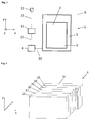
- a device 1 for heating is shown.
- This device 1 is preferably designed as a water-bearing stove 1.
- the heating device 1 preferably has a combustion chamber 2 or a combustion chamber 2 which is delimited at least by an at least partially at least partially transparent wall 4 with respect to at least one region of the surrounding space (with respect to the environment) 6.
- the wall 4 is coupled with intransparent wall parts 5 or accommodated therein.
- Such intransparent wall parts are preferably made of metal, stone or ceramic materials.
- the transparent wall 4 is at least temporarily connected to a voltage source 8 in connection.
- the voltage source 8 can be connected directly to the device 1 for heating or the wall 4 (eg in the form of a rechargeable battery or in the form of a power grid connection), wherein it is also conceivable that these are arranged spatially spaced from each other.
- a power supply can be done by cable or wirelessly.
- This control device 10 may be formed separately from the power supply 8 or together as a device.
- the control device 10 is preferably designed such that it depends on adjustable or predetermined times, of sensor signals detected by one or more sensor devices 12 and / or stored or manually / digitally predeterminable processes, the transparency and / or reflectivity of the wall, in particular by the application of voltage changes.
- the reference numeral 30 denotes a current-carrying or live line and the reference numeral 32 denotes signal-carrying connections. However, it is also conceivable that via a line 30 current and control signals are passed.
- a layer structure of an at least partially at least partially transparent wall 4 is shown. Contrary to the z-direction, ie repellent from the combustion chamber 2, this layer structure comprises successively a glass layer 14, a TCO layer 16, a first electrochromic layer 18, a polymer electrolyte foil 20, a second electrochromic layer 22, a further TCO layer 17 and a further glass layer 15.
- the layers 14, 15, 16, 17, 18, 20, 22 may have different thicknesses from each other, wherein it is also conceivable that individual or all layers have the same thickness.
- a TCO layer transparent conductive oxide
- the TCO layers are subjected to change the transparency and / or the reflectivity with voltage.
- the wall 4 is formed with only one electrochromic layer or with a plurality of electrochromic layers, in particular 3, 4, 5, 6 or more layers.
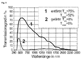
- This arrangement or the use of electrochromic glasses allows a wealth of advantages, such as that a continuous change in the transmission of light and heat is voroutlinedbar that a switching stroke in the visual range (VIS range) between preferably 8% and 75% is feasible, a contrast ratio preferably greater than 9 to 1 can be realized, that the near infrared region (NIR range) preferably also implements that a stepless change of the energy transmission between preferably 6% and 52% is adjustable and that the reflectivity does not change.
- the multilayer arrangement or the use of electrochromic glasses causes the wall 4 or the pane arrangement 4 to have laminated safety glass properties.
- Fig. 3a a first operating state of the device 1 for heating.
- the wall 4 is not subjected to a voltage or the glass has been short-circuited or the polarity of the voltage is changed such that the wall 4 is colorless.
- the external radiation 40 coming from the combustion chamber 2 the light from the visible spectrum 46 and near infrared light 48, for the most part 50, 52 are transmitted through the wall 4 therethrough. Only a small portion 54, 56 forms the reflected portion 44. From the wall 4, almost no light or substantially no light is absorbed.
- the electrochromic layers 18, 22 are colored, whereby a large part of the light portions 50, 52 is absorbed.
- the reflected portion 44 remains substantially constant. It can be seen that the absorption of the light takes place step by step independently of the respective spectrum, ie each layer 18, 22 absorbs a certain proportion of the radiation incident on it.
- the layer 18 reduces the radiation portions 46, 48 (minus the reflected portions 54, 56) to the radiation portions 58, 60 and the layer 22 the radiation portions 58, 60 on the radiation portions 50, 52.
- the circuit is thus preferably between colorless transparent ( Fig. 3a ) and, for example, blue transparent ( Fig.
- the absorbed and reflected heat is preferably used for heating the medium carried in the device 1, in particular water, that is, the water is led to the absorbed heat or the heat is conducted to the water.
- FIG. 4 an example of a wall assembly 4 of the device 1 according to the invention is shown.
- the at least temporarily transparent wall parts 66, 70 are held by intransparent wall parts 5, the storage devices 62, 64 formed.
- Reference numeral 66 denotes an electrochromic outer pane of a disk sandwich (eg in the sense of Fig. 2 ), which is connectable via a line connection, in particular a cable, and a plug 72 with the voltage source 8.
- the reference numeral 70 is an inner pane, which is preferably provided with a thermal barrier coating, characterized.
- Fig. 5 For example, two curves of the transmittance of electrochromic glass as a function of the wavelength of the light are shown as examples of defined switching states.
Landscapes
- Engineering & Computer Science (AREA)
- Chemical & Material Sciences (AREA)
- Combustion & Propulsion (AREA)
- Mechanical Engineering (AREA)
- General Engineering & Computer Science (AREA)
- Materials Engineering (AREA)
- Organic Chemistry (AREA)
- Chemical Kinetics & Catalysis (AREA)
- General Chemical & Material Sciences (AREA)
- Geochemistry & Mineralogy (AREA)
- Life Sciences & Earth Sciences (AREA)
- Solid-Fuel Combustion (AREA)
- Regulation And Control Of Combustion (AREA)
- Electrochromic Elements, Electrophoresis, Or Variable Reflection Or Absorption Elements (AREA)
Description
- Die vorliegende Erfindung bezieht sich auf eine Vorrichtung zum Heizen, insbesondere auf einen wassergeführten Kaminofen, nach dem Oberbegriff von Anspruch 1 und ein Verfahren zum Heizen nach dem Oberbegriff von Anspruch 10.
- Wasserführende Kaminöfen werden üblicherweise in Häusern mit geringem Energiebedarf genutzt. In einem definierten Verteilungsverhältnis ihrer Wärmeabgabe von z.B. 70 % an Wasser und 30 % an die umgebende Luft (z.B. Aufstellraum) werden diese Geräte bevorzugt mit Brennstoffen aus nachwachsenden Rohstoffen wie z.B. Holz in unterschiedlichen Formen (Scheitholz, Briketts, Pellets) betrieben. Die bei der Verbrennung entstehende Energie wird entsprechend dieser fixen Anteile durch die am Ofen angebrachten Wassertaschen in das Heizungssystem eingetragen bzw. als Strahlungswärme über die Scheibe der Tür in den Aufstellraum abgegeben. Als Scheibenmaterial werden üblicherweise Borsilikatglas mit einem hohen Siliziumanteil oder Quarzgläser verwendet.
- Derartige Vorrichtungen zum Heizen weisen das Problem auf, dass das über u.a. die Größe der Wärmeübertragerflächen respektive Scheibengröße festgelegte Verteilungsverhältnis zwischen Wasser und Luft nicht weiter veränderbar (zum Beispiel steuerbar) ist. Somit muss bereits beim Kauf des Gerätes eine Entscheidung über die Verteilung der Nutzung der entstehenden Wärme getroffen werden. Eine flexible Nutzung unter Berücksichtigung des aktuellen Wärmebedarfes ist bisher nicht möglich.
- Es ist somit Aufgabe der vorliegenden Erfindung eine Vorrichtung zum Heizen, insbesondere einen wassergeführten Kaminofen, derart weiterzuentwickeln, dass die Energieabgabe an die Umgebung (an den umgebenden Raum) bei gegebener Wärmestrahlung veränderbar ist.
- Die
US 2008/0145625 A1 offenbart ein Verfahren zur Herstellung eines Substrats mit einem Layer, wobei eine beispielhafte Verwendung des Substrats ein Glassichtfeld bei einem Kamin betrifft. - Die nachveröffentlichte
WO 2012/062467 A1 zeigt ein Erzeugnis mit einem Glas- oder Glaskeramik-Substrat, welches mit einer ein Metalloxid enthaltenden Schicht beaufschlagt ist, wobei eine angegebene Nutzung Vorrichtungen zur Wärmeerzeugung wie Kamine oder Kaminöfen betrifft. - Die
DE 102008064357 A1 beschreibt eine optisch aktive Verglasung, bei der eine optische Eigenschaft durch Zuführen elektrischer Leistung veränderbar ist, mit einer elektrischen Leistungsquelle, die mit der optisch aktiven Verglasung elektrisch verbindbar ist. - Die Lösung der zuvor genannten Aufgabe erfolgt durch eine Vorrichtung zum Heizen mit einer Brennkammer zum Aufnehmen von Brennstoff (Brenngut), wobei die Brennkammer zumindest abschnittsweise von einer zumindest teilweise transparenten und/oder teilweise reflektierenden Wandung zur Abgrenzung gegenüber einem umgebenden Raum umschlossen ist, wobei das transparente Wandungsteil zumindest teilweise aus elektrochromem Glas besteht und der Grad der Transparenz und/oder der Grad der Reflexion der Wandung einstellbar. Diese Einstellung umfasst ein Ein- / Ausschalten, ein mehrstufiges sowie ein stufenloses Variieren.
- Dies ist vorteilhaft, da elektrochromes Glas zum einen sehr hitzebeständig ausgestaltet werden kann und zum anderen einfach, dauerhaft und schnell die Eigenschaften des elektrochromen Glases hinsichtlich Lichtdurchlässigkeit (oder allgemein: Energiedurchlässigkeit) durch Spannungsbeaufschlagung veränderbar sind. Insbesondere ist durch eine Veränderung des Grades der Reflexion und/oder der Transparenz der Wandung die Wärmeübertragung, z.B. bei konstant strahlender Wärmequelle, aus der Vorrichtung heraus in den zu erwärmenden Raum hinein einstellbar.
- Es ist eine Spannungsquelle zum Beaufschlagen des elektrochromen Glases mit einer Spannung vorgesehen. Dabei kann die Wandung aus einer einfachen beschichteten Glasscheibe oder auch aus einem Verbund zweier oder mehrerer Glasscheiben und/oder Beschichtungen bestehen. Die Spannung ist mittels einer Regelungseinrichtung manuell und/oder automatisch einstellbar. Dies ist vorteilhaft, da im Falle einer manuellen Einstellung die Nutzer je nach Situation die Wärmeübertragung verändern können. Im Falle der automatischen Einstellung ist die Regelungseinrichtung bevorzugt eine Recheneinheit, die zeitbasiert, temperaturbasiert und/oder programmbasiert eine Veränderung, d.h. Erhöhung oder Verminderung der Transparenz und/oder Reflexion, durchführt.
- Erfindungsgemäß sind Sensorsignale von der Regelungseinrichtung auswertbar und/oder es sind von der Regelungseinrichtung programmierte Ansteuerungsverläufe ausführbar.
- Dies ist vorteilhaft, da eine teilweise oder vollständig autonome Steuerung der Temperierung des die Vorrichtung umgebenden Raums möglich ist.
- Dabei sind die Sensorsignale von mindestens einer Sensoreinrichtung, ausgewählt aus der Gruppe bevorzugt zumindest bestehend aus einem Lichtsensor zum Erfassen der Lichtverhältnisse in dem die Vorrichtung umgebenden Raum, einem Temperatursensor zum Erfassen der Temperatur in dem die Vorrichtung umgebenden Raum und/oder in der Vorrichtung, einem Mengensensor (zum Beispiel Gewichtssensor, Füllstandssensor) zum direkten oder indirekten Erfassen des noch im Brennraum vorhandenen Brennstoffs oder Kombinationen daraus, erfassbar. Dies ist vorteilhaft, da die Temperierung des die Vorrichtung umgebenden Raums somit von einem und bevorzugt von einer Mehrzahl an Einflussfaktoren abhängig machbar ist. Wird beispielsweise erkannt, dass die Dämmerung einsetzt und sich somit die durch das Sonnenlicht eingestrahlte Wärme reduziert, kann zeitgleich die verbleibende Restenergiemenge des Brennstoffs durch eine Erhöhung der Transparenz und/oder eine Verminderung der Reflektivität zum Ausgleich in den zu erwärmenden Raum geleitet werden.
- Gemäß einer bevorzugten Ausführungsform der vorliegenden Erfindung ist das elektrochrome Glas mit einem Material beschichtet, das auswählbar ist aus einer Materialgruppe umfassend Übergangsmetalle, Übergangsmetalloxide, leitfähige Polymere, Verbindungen aus mindestens einem Übergangsmetall und/oder einem Übergangsmetalloxid mit mindestens einem leitfähigen Polymer und/oder Kombinationen daraus. Übergangsmetalle, auch Übergangselemente genannt, sind chemische Elemente mit den Ordnungszahlen 21 bis 30, 39 bis 48, 57 bis 80 und 89 bis 112, und umfassen unter anderem Wolfram und Molybdän. Elektrisch leitfähige Polymere sind wie beispielsweise Polyanilin entweder intrinsisch (von sich aus) leitfähig oder sie erhalten ihre elektrische Leitfähigkeit durch Zugabe von Salzen.
- Diese Ausführungsform ist vorteilhaft, da die Herstellung von elektrochromen Glas durch die Verwendung dieser Materialien günstig durchführbar ist. Ferner ist die Ansprechzeit, die Beständigkeit und die Funktionssicherheit bei der Verwendung dieser Materialien am besten.
- Eine mögliche zweite funktionale Scheibe im zu erstellenden Verbund kann Verbindungen aus der Gruppe der Alkalimetalle (Lithium u.a.) und/oder Erdalkalimetalle (Beryllium u.a.) beinhalten, die z.B. in ionischer Form vorliegen können.
- Gemäß der vorliegenden Erfindung ist die Regelungseinrichtung mittels eines daran angeordneten Eingabemittels oder über eine drahtlose Verbindung ansteuerbar.
- Diese Ausführungsform ist vorteilhaft, da das Eingabemittel dabei z.B. als Drehschalter, Kippschalter etc. ausgebildet sein kann, wodurch eine Ansteuerung ergonomisch optimal angepasst erfolgen kann. Im Falle einer drahtlosen Verbindung erfolgt bevorzugt über ein Bluetooth-, Wi-Fi- oder Telefonverbindung die Kommunikation zwischen der Regelungseinrichtung und dem Eingabemittel, das z.B. als Mobilteil, insbesondere Mobiltelefon, bzw. eine auf dem Mobilteil/Mobiltelefon ablauffähiges Programm, ausgebildet sein kann.
- Gemäß einer weiteren bevorzugten Ausführungsform der vorliegenden Erfindung ist die Vorrichtung zum Heizen ein wasserführender Kaminofen.
- Diese Ausführungsform ist vorteilhaft, da dies eine Massenanwendung in privaten und gewerblichen Räumlichkeiten ermöglicht, wodurch ein deutlicher Beitrag zur intelligenten Energienutzung gegeben ist. Ferner ist die Energieerzeugung aus nachwachsenden Rohstoffen, wie Holz, möglich, wodurch die Abhängigkeit von Öl und Gas reduziert wird. Es ist jedoch ebenfalls denkbar, dass in dem Ofen Öl und/oder Gas als Brennstoff verwendet wird.
- Weiterhin wird die oben genannte Aufgabe durch ein Verfahren zum Heizen mittels einer erfindungsgemäßen Vorrichtung zum Heizen gelöst, das mindestens den Schritt des Verbrennens von Brenngut in einer Brennkammer, wobei die Brennkammer zumindest abschnittsweise von einer zumindest teilweise transparenten Wandung zur Abgrenzung gegenüber einem umgebenden Raum umschlossen ist und wobei die durch die Verbrennung entstehende Wärmestrahlung zumindest teilweise durch die zumindest zeitweise teilweise transparente Wandung hindurchdringt, umfasst. Erfindungsgemäß ist in einem zweiten Schritt eine beliebige Veränderung des Anteils der die Wandung durchdringenden Wärme mittels einer Veränderung des Grades der Transparenz und/oder des Grades der Reflexion der Wandung erreichbar.
- Weitere Vorteile, Ziele und Eigenschaften vorliegender Erfindung werden anhand nachfolgender Beschreibung anliegender Zeichnungen erläutert, in welchen beispielhaft Vorrichtungen zum Heizen dargestellt sind. Bauteile der Vorrichtungen zum Heizen, welche in den Figuren wenigsten im Wesentlichen hinsichtlich ihrer Funktion übereinstimmen, können hierbei mit gleichen Bezugszeichen gekennzeichnet sein, wobei diese Bauteile nicht in allen Figuren beziffert oder erläutert sein müssen.
- Darin zeigen:
- Fig. 1
- eine erfindungsgemäße Vorrichtung zum Heizen;
- Fig. 2
- einen Aufbau einer zumindest zeitweise teilweise transparenten und/oder reflektierenden Wandung;
- Fig. 3a
- die in
Fig. 2 gezeigte Wandung in einem ersten Zustand; - Fig. 3b
- die in
Fig. 2 gezeigte Wandung in einem zweiten Zustand; - Fig. 4
- eine perspektivische Darstellung einer zumindest zeitweise teilweise transparenten und/oder reflektierenden Wandungseinrichtung; und
- Fig. 5
- eine Darstellung des Anteils des transmittierten Lichts in Abhängigkeit von der Wellenlänge des Lichts.
- In
Fig. 1 ist eine Vorrichtung 1 zum Heizen gezeigt. Diese Vorrichtung 1 ist bevorzugt als wasserführender Kaminofen 1 ausgebildet. Die Vorrichtung 1 zum Heizen weist bevorzugt eine Brennstelle 2 bzw. eine Brennkammer 2 auf, die zumindest durch eine zumindest zeitweise zumindest teilweise transparente Wandung 4 gegenüber zumindest einem Bereich des umgebenden Raums (gegenüber der Umgebung) 6 abgegrenzt ist. Es ist ebenfalls denkbar, dass die Wandung 4 mit intransparenten Wandungsteilen 5 gekoppelt bzw. darin aufgenommen ist. Derartige intransparente Wandungsteile bestehen bevorzugt aus Metall, Stein oder keramischen Materialien. Die transparente Wandung 4 steht zumindest zeitweise mit einer Spannungsquelle 8 in Verbindung. Die Spannungsquelle 8 kann dabei direkt mit der Vorrichtung 1 zum Heizen oder der Wandung 4 (z.B. in Form eines Akkumulators oder in Form einer Stromnetzverbindung) verbunden sei, wobei ebenfalls vorstellbar ist, dass diese räumlich voneinander beabstandet angeordnet sind. Eine Spannungsversorgung kann dabei mittels Kabel oder kabellos erfolgen. Weiterhin weist die Vorrichtung 1 zum Heizen eine Steuereinrichtung 10 bzw. eine Regelungseinrichtung 10 auf. Diese Regelungseinrichtung 10 kann dabei getrennt von der Spannungsversorgung 8 oder gemeinsam als eine Einrichtung ausgebildet sein. Die Regelungseinrichtung 10 ist bevorzugt derart ausgebildet, dass sie in Abhängigkeit von einstellbaren oder vorgegebenen Zeitpunkten, von durch eine oder mehrere Sensoreinrichtungen 12 erfasste Sensorsignale und/oder gespeicherte bzw. manuell/digital vorgebbare Abläufe die Transparenz und/oder Reflektivität der Wandung, insbesondere durch die Beaufschlagung mit Spannung, ändert. Das Bezugszeichen 30 kennzeichnet eine stromführende oder spannungsführende Leitung und das Bezugszeichen 32 kennzeichnet signalführende Verbindungen. Es ist jedoch ebenfalls vorstellbar, dass über eine Leitung 30 Strom und Steuersignale geleitet werden. - In
Fig. 2 ist ein Schichtaufbau einer zumindest zeitweise zumindest teilweise transparenten Wandung 4 dargestellt. Dieser Schichtaufbau umfasst entgegen der z-Richtung, d.h. von der Brennkammer 2 abweisend, nacheinander eine Glasschicht 14, eine TCO-Schicht 16, eine erste elektrochrome Schicht 18, eine Polymerelektrolytfolie 20, eine zweite elektrochrome Schicht 22, eine weitere TCO-Schicht 17 sowie eine weitere Glasschicht 15. Die Schichten 14, 15, 16, 17, 18, 20, 22 können dabei voneinander verschiedene Dicken aufweisen, wobei auch denkbar ist, dass einzelne oder alle Schichten dieselbe Dicke aufweisen. Eine TCO-Schicht (transparent conductive oxide, transparentes elektrisch leitfähiges Oxid) ist eine Schicht aus speziellen elektrisch leitfähigen Materialien mit einer vergleichsweise geringen Absorption von elektromagnetischen Wellen im Bereich des sichtbaren Lichts. Bevorzugt werden die TCO-Schichten zum Verändern der Transparenz und/oder der Reflektivität mit Spannung beaufschlagt. Es ist denkbar, dass die Wandung 4 mit nur einer elektrochromen Schicht oder mit einer Mehrzahl elektrochromer Schichten, insbesondere 3, 4, 5, 6 oder mehr Schichten, ausgebildet wird. Diese Anordnung bzw. die Verwendung elektrochromer Gläser ermöglicht eine Fülle von Vorteilen, wie z.B. dass eine stufenlose Änderung der Transmission von Licht und Wärme vornehmbar ist, dass ein Schalthub im visuellen Bereich (VIS-Bereich) zwischen bevorzugt 8 % und 75 % realisierbar ist, dass ein Kontrastverhältnis bevorzugt größer 9 zu 1 realisierbar ist, dass der nahe Infrarotbereich (NIR-Bereich) bevorzugt mitschaltet, dass eine stufenlose Änderungen der Energietransmission zwischen bevorzugt 6 % und 52 % einstellbar ist und dass sich die Reflektivität nicht ändert. Ferner bewirkt die mehrschichtige Anordnung bzw. die Verwendung elektrochromer Gläser, dass die Wandung 4 bzw. die Scheibenanordnung 4 Verbundsicherheitsglaseigenschaften aufweist. - In
Fig. 3a ist ein erster Betriebszustand der Vorrichtung 1 zum Heizen dargestellt. Gemäß dieser Darstellung ist die Wandung 4 nicht mit einer Spannung beaufschlagt bzw. das Glas wurde kurzgeschlossen oder die Polarität der Spannung derart geändert, dass die Wandung 4 farblos ist. In diesem Zustand kann die aus der Brennkammer 2 kommende externe Einstrahlung 40, die Licht aus dem sichtbaren Spektrum 46 und nahes Infrarotlicht 48 umfasst, zu einem Großteil 50, 52 durch die Wandung 4 hindurch transmittiert werden. Lediglich ein geringer Anteil 54, 56 bildet den reflektierten Anteil 44. Von der Wandung 4 wird nahezu kein Licht bzw. im Wesentlichen kein Licht absorbiert. - In
Fig. 3b sind die elektrochromen Schichten 18, 22 eingefärbt, wodurch ein großer Teil der Lichtanteile 50, 52 absorbiert wird. Der reflektierte Anteil 44 bleibt dabei im Wesentlichen konstant. Es ist ersichtlich, dass die Absorption des Lichts unabhängig von dem jeweiligen Spektrum schrittweise erfolgt, d.h. jede Schicht 18, 22 absorbiert einen gewissen Anteil der auf ihr auftreffenden Strahlung. So reduziert die Schicht 18 die Strahlungsanteile 46, 48 (abzüglich der reflektierten Anteile 54, 56) auf die Strahlungsanteile 58, 60 und die Schicht 22 die Strahlungsanteile 58, 60 auf die Strahlungsanteile 50, 52. Die Schaltung erfolgt somit bevorzugt zwischen farblos transparent (Fig. 3a ) und beispielsweise blau transparent (Fig. 3b ) und bevorzugt unter dem Anlegen einer Gleichspannung im Niederspannungsbereich, insbesondere in einem Bereich zwischen 1 und 10 Volt und bevorzugt zwischen 2 und 5 Volt und bevorzugt bei genau 3 Volt. Weiterhin sind graduelle Änderungen des Färbungsgrades einstellbar und die Spannung muss besonders bevorzugt nur während des Schaltvorgangs anliegen. Die absorbierte und die reflektierte Wärme wird bevorzugt zum Heizen des in der Vorrichtung 1 geführten Mediums, insbesondere Wasser, verwendet, d.h. dass das Wasser zur absorbierten Wärme hingeführt wird oder die Wärme zum Wasser geführt wird. - In
Figur 4 ist ein Beispiel einer Wandungsanordnung 4 der erfindungsgemäßen Vorrichtung 1 dargestellt. Die zumindest zeitweise transparenten Wandungsteile 66, 70 werden dabei von intransparenten Wandungsteilen 5, die Lagerungseinrichtungen 62, 64 ausbilden, gehalten. Das Bezugszeichen 66 kennzeichnet eine elektrochrome Außenscheibe eines Scheibensandwiches (z.B. im Sinne vonFig. 2 ), das über eine Leitungsverbindung, insbesondere ein Kabel, und einen Stecker 72 mit der Spannungsquelle 8 verbindbar ist. Durch das Bezugszeichen 70 ist eine Innenscheibe, die bevorzugt mit einer Wärmedämmschicht versehen ist, gekennzeichnet. - In
Fig. 5 sind zwei Verläufe des Transmissionsgrades elektrochromen Glases in Abhängigkeit der Wellenlänge des Lichts repräsentativ für definierte Schaltzustände exemplarisch abgebildet. - An dieser Stelle sei noch darauf hingewiesen, dass sich die Anmelderin vorbehält sämtliche in den Anmeldungsunterlagen offenbarten Merkmale zu beanspruchen soweit sie einzeln oder in Kombination miteinander gattungsgemäße oder aus dem Stand der Technik bekannte Vorrichtungen zum Heizen vorteilhaft weiterentwickeln.
-
- 1
- Vorrichtung zum Heizen
- 2
- Brennkammer
- 4
- Teilweise transparente Wandung
- 5
- Wandung
- 6
- umgebender Raum, Umgebung
- 8
- Spannungsquelle
- 10
- Regelungseinrichtung / Steuereinrichtung
- 12
- Sensoreinrichtung
- 14
- Glasschicht
- 15
- Weitere Glasschicht
- 16
- TCO-Schicht
- 17
- Weitere TCO-Schicht
- 18
- Erste elektrochrome Schicht
- 20
- Polymerelektrolytfolie
- 22
- Zweite elektrochrome Schicht
- 24
- Erster Kontakt
- 26
- Zweiter Kontakt
- 30
- Stromführende Verbindung
- 32
- Signalführende Verbindung
- 40
- Externe Einstrahlung
- 42
- Transmittiertes Licht
- 44
- Reflektierter Anteil
- 46
- Visueller Bereich
- 48
- Nahes Infrarot
- 50
- Transmittiertes visuelles Licht
- 52
- Transmittiertes nahes Infrarotlicht
- 54
- Reflektiertes visuelles Licht
- 56
- Reflektiertes nahes Infrarotlicht
- 58
- Einfach gefiltertes visuelles Licht
- 60
- Einfach gefiltertes nahes Infrarotlicht
- 62
- Erste Lagerungseinrichtung
- 64
- Zweite Lagerungseinrichtung
- 66
- Elektrochrome Außenscheibe
- 68
- Scheibenzwischenraum
- 70
- Innenscheibe mit Wärmedämmbeschichtung
- 72
- Kabel mit Stecker zur Steuereinheit / Regelungseinrichtung
- x
- Erste Richtung
- y
- Zweite Richtung
- z
- Dritte Richtung
Claims (4)
- Vorrichtung zum Heizen (1) mit einer Brennkammer (2) zum Aufnehmen von Brennstoff, wobei die Brennkammer (2) zumindest abschnittsweise von einer zumindest teilweise transparenten und/oder zumindest teilweise reflektierenden Wandung (4) zur Abgrenzung gegenüber einem umgebenden Raum (6) umschlossen ist,
wobei der transparente Wandungsteil (4) zumindest teilweise aus elektrochromem Glas besteht und der Grad der Transparenz und/oder der Grad der Reflexion der Wandung (4) einstellbar ist, wobei eine Spannungsquelle (8) zum Beaufschlagen des elektrochromen Glases mit einer Spannung vorgesehen und die Spannung mittels einer Regelungseinrichtung (10) manuell oder automatisch einstellbar ist
dadurch gekennzeichnet, dass die Regelungseinrichtung (10) mittels eines daran angeordneten Eingabemittels oder über eine drahtlose Verbindung ansteuerbar ist, und dass Sensorsignale von der Regelungseinrichtung (10) auswertbar und/oder von der Regelungseinrichtung (10) programmierte Ansteuerungsverläufe ausführbar sind, wobei die Sensorsignale von mindestens einer Sensoreinrichtung (12), ausgewählt aus der Gruppe zumindest bestehend aus einem Lichtsensor zum Erfassen der Lichtverhältnisse in dem die Vorrichtung umgebenden Raum (6), einem Temperatursensor zum Erfassen der Temperatur in dem die Vorrichtung umgebenden Raum (6) und/oder in der Vorrichtung (1), einem Mengensensor zum Erfassen des noch im Brennraum (2) vorhandenen Brennstoffs oder Kombinationen daraus, erfassbar sind. - Vorrichtung nach Anspruch 2,
dadurch gekennzeichnet, dass das elektrochrome Glas mit einem Material, ausgewählt aus einer Materialgruppe umfassend Übergangsmetalle, Übergangsmetalloxide, leitfähige Polymere, Verbindungen aus mindestens einem Übergangsmetall und/oder einem Übergangsmetalloxid mit mindestens einem leitfähigen Polymer und/oder Kombinationen daraus, beschichtet ist. - Vorrichtung nach einem der vorangegangenen Ansprüche,
dadurch gekennzeichnet, dass die Vorrichtung zum Heizen (1) ein wasserführender Kaminofen ist. - Verfahren zum Heizen (1), mindestens umfassend die Schritte:• Verbrennen von Brenngut in einer Brennkammer (2),• wobei die Brennkammer (2) zumindest abschnittsweise von einer zumindest teilweise transparenten Wandung (4) und/oder von einer zumindest teilweise reflektierenden Wandung (4) zur Abgrenzung gegenüber einem umgebenden Raum (6) umschlossen ist,• wobei die durch die Verbrennung entstehende Wärmestrahlung zumindest teilweise durch die zumindest zeitweise teilweise transparente und/oder teilweise reflektierende Wandung (4) hindurchdringt und eine Veränderung des Anteils der die Wandung (4) durchdringenden Wärme mittels einer Veränderung des Grades der Transparenz und/oder des Grades der Reflexion der Wandung (4) bewirkt wird, indem eine ein elektrochromes Glas beaufschlagende Spannung mittels einer Regelungseinrichtung (10) manuell oder automatisch eingestellt wird,dadurch gekennzeichnet, dass die Regelungseinrichtung (10) mittels eines daran angeordneten Eingabemittels oder über eine drahtlose Verbindung angesteuert ist, und die Regelungseinrichtung (10) Sensorsignale auswertet und/oder programmierte Ansteuerungsverläufe ausführt, wobei die Sensorsignale von mindestens einer Sensoreinrichtung (12), ausgewählt aus der Gruppe zumindest bestehend aus einem Lichtsensor zum Erfassen der Lichtverhältnisse in dem die Vorrichtung umgebenden Raum (6), einem Temperatursensor zum Erfassen der Temperatur in dem die Vorrichtung umgebenden Raum (6) und/oder in der Vorrichtung (1), einem Mengensensor zum Erfassen des noch im Brennraum (2) vorhandenen Brennstoffs oder Kombinationen daraus, erfasst werden.
Applications Claiming Priority (1)
| Application Number | Priority Date | Filing Date | Title |
|---|---|---|---|
| DE102011121106A DE102011121106A1 (de) | 2011-12-15 | 2011-12-15 | Vorrichtung zum Heizen |
Publications (2)
| Publication Number | Publication Date |
|---|---|
| EP2604928A1 EP2604928A1 (de) | 2013-06-19 |
| EP2604928B1 true EP2604928B1 (de) | 2016-10-12 |
Family
ID=47519837
Family Applications (1)
| Application Number | Title | Priority Date | Filing Date |
|---|---|---|---|
| EP12196709.5A Not-in-force EP2604928B1 (de) | 2011-12-15 | 2012-12-12 | Vorrichtung zum Heizen |
Country Status (2)
| Country | Link |
|---|---|
| EP (1) | EP2604928B1 (de) |
| DE (1) | DE102011121106A1 (de) |
Family Cites Families (9)
| Publication number | Priority date | Publication date | Assignee | Title |
|---|---|---|---|---|
| KR20020002420A (ko) * | 1999-04-06 | 2002-01-09 | 레베오 인코포레이티드 | 산란 및 투과 작동 모드를 갖는 전자 광학적 글레이징구조물 |
| DE102005036427A1 (de) * | 2005-08-03 | 2007-02-08 | Schott Ag | Substrat, umfassend zumindest eine voll- oder teilflächige makrostrukturierte Schicht, Verfahren zu deren Herstellung und deren Verwendung |
| DE202005016163U1 (de) * | 2005-10-11 | 2006-02-09 | Proventecs Gmbh | Sichtöffnung für Öfen mit geringer Wärmeabgabe |
| KR20080050354A (ko) * | 2007-12-17 | 2008-06-05 | 박용성 | 조광유리 구동시스템 |
| DE102008025156A1 (de) * | 2008-05-26 | 2009-12-03 | Stachel Ag | Glaskeramikscheibenheizung |
| US8790537B2 (en) * | 2008-06-09 | 2014-07-29 | Council Of Scientific & Industrial Research | Process for the preparation of solid polymer electrolytes using ionic liquids |
| DE102008030825A1 (de) * | 2008-06-30 | 2009-12-31 | Schott Ag | Vorrichtung zur Reflektion von Wärmestrahlung, ein Verfahren zu ihrer Herstellung sowie deren Verwendung |
| DE102008064357A1 (de) * | 2008-12-20 | 2010-06-24 | Saint-Gobain Sekurit Deutschland Gmbh & Co. Kg | Optisch aktive Verglasung mit Überspannungsschutz |
| DE102010050771B4 (de) * | 2010-11-10 | 2014-05-08 | Schott Ag | Erzeugnis aus Glas oder Glaskeramik mit hochtemperaturstabiler Niedrigenergie-Schicht, Verfahren zur Herstellung derselben und Verwendung des Erzeugnisses |
-
2011
- 2011-12-15 DE DE102011121106A patent/DE102011121106A1/de not_active Withdrawn
-
2012
- 2012-12-12 EP EP12196709.5A patent/EP2604928B1/de not_active Not-in-force
Non-Patent Citations (1)
| Title |
|---|
| None * |
Also Published As
| Publication number | Publication date |
|---|---|
| DE102011121106A1 (de) | 2013-06-20 |
| EP2604928A1 (de) | 2013-06-19 |
Similar Documents
| Publication | Publication Date | Title |
|---|---|---|
| DE102008030825A1 (de) | Vorrichtung zur Reflektion von Wärmestrahlung, ein Verfahren zu ihrer Herstellung sowie deren Verwendung | |
| EP2236473B1 (de) | Infrarot-Strahlung reflektierende Glas-oder Glaskeramikscheibe | |
| DE2934995A1 (de) | Vorrichtung zur verwendung von solarenergie fuer beleuchtung von geschlossenen raeumen | |
| DE4128645A1 (de) | Solarspiegel, verfahren zu dessen herstellung und seine verwendung | |
| DE102005016389A1 (de) | Verbundscheibe | |
| DE102013210823B3 (de) | LED-Heißraumleuchte sowie diese Heißraumleuchte enthaltendes Haushaltsgerät | |
| EP4217197A1 (de) | Verbundscheibe mit elektrisch steuerbaren optischen eigenschaften | |
| EP3995462A1 (de) | Glas- oder glaskeramikelement umfassend glas- oder glaskeramiksubstrat und beschichtung sowie verfahren zu dessen herstellung und dessen verwendung | |
| EP2604928A1 (de) | Vorrichtung zum Heizen | |
| EP2582640A1 (de) | Auskleidungs- oder reflektormaterial für hochtemperaturanwendungen | |
| DE2710483A1 (de) | Verfahren zum niederschlagen einer schicht | |
| DE202005007474U1 (de) | Leichter Sonnenkollektor mit integriertem Überhitzungsschutz | |
| EP1816308B1 (de) | Vorrichtung zum Verschatten von Gebäudeöffnungen mit einem Sensor | |
| DE202021100462U1 (de) | Fahrzeugscheibe | |
| EP2000748A2 (de) | Kollektorelement zur Wärmegewinnung aus der Sonnenstrahlung und Schutzabdeckung dafür | |
| WO2004036122A1 (de) | Vorrichtung zur aufnahme von sonnenenergie | |
| EP2610425B1 (de) | Fensterelement mit integrierter Lichtquelle | |
| DE2502594C2 (de) | Sonnenkollektor mit einem aus Metallblechen bestehenden Absorber mit Kanälen für eine die absorbierte Wärme abführende Flüssigkeit | |
| DE202021103109U1 (de) | Fahrzeugglastür mit integriertem Sensorschaltelement zum Öffnen und Schließen der Tür | |
| AT524132B9 (de) | Aufsatzvorrichtung für ein Okular oder Objektiv einer fernoptischen Vorrichtung | |
| AT407324B (de) | Flächenheizeinrichtung mit einem mehrschichtigen, bevorzugt transparenten, flächenelement und verfahren zum betrieb | |
| EP2465175A1 (de) | Solarzelle | |
| DE102004030086A1 (de) | Verglasungselement im Sandwichaufbau | |
| DE102004046033A1 (de) | Energie sparende Heizeinrichtung | |
| DE102019102559B4 (de) | Kaminofen |
Legal Events
| Date | Code | Title | Description |
|---|---|---|---|
| PUAI | Public reference made under article 153(3) epc to a published international application that has entered the european phase |
Free format text: ORIGINAL CODE: 0009012 |
|
| AK | Designated contracting states |
Kind code of ref document: A1 Designated state(s): AL AT BE BG CH CY CZ DE DK EE ES FI FR GB GR HR HU IE IS IT LI LT LU LV MC MK MT NL NO PL PT RO RS SE SI SK SM TR |
|
| AX | Request for extension of the european patent |
Extension state: BA ME |
|
| 17P | Request for examination filed |
Effective date: 20131219 |
|
| RBV | Designated contracting states (corrected) |
Designated state(s): AL AT BE BG CH CY CZ DE DK EE ES FI FR GB GR HR HU IE IS IT LI LT LU LV MC MK MT NL NO PL PT RO RS SE SI SK SM TR |
|
| REG | Reference to a national code |
Ref country code: DE Ref legal event code: R079 Ref document number: 502012008482 Country of ref document: DE Free format text: PREVIOUS MAIN CLASS: F24B0001192000 Ipc: B32B0017100000 |
|
| GRAP | Despatch of communication of intention to grant a patent |
Free format text: ORIGINAL CODE: EPIDOSNIGR1 |
|
| RIC1 | Information provided on ipc code assigned before grant |
Ipc: F23M 5/00 20060101ALI20160606BHEP Ipc: C03C 17/42 20060101ALI20160606BHEP Ipc: F23M 7/00 20060101ALI20160606BHEP Ipc: C09K 9/00 20060101ALI20160606BHEP Ipc: F24B 1/192 20060101ALI20160606BHEP Ipc: B32B 17/10 20060101AFI20160606BHEP Ipc: F24B 13/00 20060101ALI20160606BHEP |
|
| INTG | Intention to grant announced |
Effective date: 20160712 |
|
| GRAS | Grant fee paid |
Free format text: ORIGINAL CODE: EPIDOSNIGR3 |
|
| GRAA | (expected) grant |
Free format text: ORIGINAL CODE: 0009210 |
|
| AK | Designated contracting states |
Kind code of ref document: B1 Designated state(s): AL AT BE BG CH CY CZ DE DK EE ES FI FR GB GR HR HU IE IS IT LI LT LU LV MC MK MT NL NO PL PT RO RS SE SI SK SM TR |
|
| REG | Reference to a national code |
Ref country code: GB Ref legal event code: FG4D Free format text: NOT ENGLISH |
|
| REG | Reference to a national code |
Ref country code: CH Ref legal event code: EP |
|
| REG | Reference to a national code |
Ref country code: AT Ref legal event code: REF Ref document number: 836126 Country of ref document: AT Kind code of ref document: T Effective date: 20161015 |
|
| REG | Reference to a national code |
Ref country code: IE Ref legal event code: FG4D Free format text: LANGUAGE OF EP DOCUMENT: GERMAN |
|
| REG | Reference to a national code |
Ref country code: DE Ref legal event code: R096 Ref document number: 502012008482 Country of ref document: DE |
|
| REG | Reference to a national code |
Ref country code: LT Ref legal event code: MG4D |
|
| REG | Reference to a national code |
Ref country code: NL Ref legal event code: MP Effective date: 20161012 |
|
| PG25 | Lapsed in a contracting state [announced via postgrant information from national office to epo] |
Ref country code: LV Free format text: LAPSE BECAUSE OF FAILURE TO SUBMIT A TRANSLATION OF THE DESCRIPTION OR TO PAY THE FEE WITHIN THE PRESCRIBED TIME-LIMIT Effective date: 20161012 |
|
| PG25 | Lapsed in a contracting state [announced via postgrant information from national office to epo] |
Ref country code: NO Free format text: LAPSE BECAUSE OF FAILURE TO SUBMIT A TRANSLATION OF THE DESCRIPTION OR TO PAY THE FEE WITHIN THE PRESCRIBED TIME-LIMIT Effective date: 20170112 Ref country code: GR Free format text: LAPSE BECAUSE OF FAILURE TO SUBMIT A TRANSLATION OF THE DESCRIPTION OR TO PAY THE FEE WITHIN THE PRESCRIBED TIME-LIMIT Effective date: 20170113 Ref country code: SE Free format text: LAPSE BECAUSE OF FAILURE TO SUBMIT A TRANSLATION OF THE DESCRIPTION OR TO PAY THE FEE WITHIN THE PRESCRIBED TIME-LIMIT Effective date: 20161012 Ref country code: LT Free format text: LAPSE BECAUSE OF FAILURE TO SUBMIT A TRANSLATION OF THE DESCRIPTION OR TO PAY THE FEE WITHIN THE PRESCRIBED TIME-LIMIT Effective date: 20161012 |
|
| PG25 | Lapsed in a contracting state [announced via postgrant information from national office to epo] |
Ref country code: NL Free format text: LAPSE BECAUSE OF FAILURE TO SUBMIT A TRANSLATION OF THE DESCRIPTION OR TO PAY THE FEE WITHIN THE PRESCRIBED TIME-LIMIT Effective date: 20161012 Ref country code: BE Free format text: LAPSE BECAUSE OF NON-PAYMENT OF DUE FEES Effective date: 20161231 Ref country code: IS Free format text: LAPSE BECAUSE OF FAILURE TO SUBMIT A TRANSLATION OF THE DESCRIPTION OR TO PAY THE FEE WITHIN THE PRESCRIBED TIME-LIMIT Effective date: 20170212 Ref country code: ES Free format text: LAPSE BECAUSE OF FAILURE TO SUBMIT A TRANSLATION OF THE DESCRIPTION OR TO PAY THE FEE WITHIN THE PRESCRIBED TIME-LIMIT Effective date: 20161012 Ref country code: HR Free format text: LAPSE BECAUSE OF FAILURE TO SUBMIT A TRANSLATION OF THE DESCRIPTION OR TO PAY THE FEE WITHIN THE PRESCRIBED TIME-LIMIT Effective date: 20161012 Ref country code: FI Free format text: LAPSE BECAUSE OF FAILURE TO SUBMIT A TRANSLATION OF THE DESCRIPTION OR TO PAY THE FEE WITHIN THE PRESCRIBED TIME-LIMIT Effective date: 20161012 Ref country code: PT Free format text: LAPSE BECAUSE OF FAILURE TO SUBMIT A TRANSLATION OF THE DESCRIPTION OR TO PAY THE FEE WITHIN THE PRESCRIBED TIME-LIMIT Effective date: 20170213 Ref country code: RS Free format text: LAPSE BECAUSE OF FAILURE TO SUBMIT A TRANSLATION OF THE DESCRIPTION OR TO PAY THE FEE WITHIN THE PRESCRIBED TIME-LIMIT Effective date: 20161012 Ref country code: PL Free format text: LAPSE BECAUSE OF FAILURE TO SUBMIT A TRANSLATION OF THE DESCRIPTION OR TO PAY THE FEE WITHIN THE PRESCRIBED TIME-LIMIT Effective date: 20161012 |
|
| REG | Reference to a national code |
Ref country code: DE Ref legal event code: R097 Ref document number: 502012008482 Country of ref document: DE |
|
| PG25 | Lapsed in a contracting state [announced via postgrant information from national office to epo] |
Ref country code: SK Free format text: LAPSE BECAUSE OF FAILURE TO SUBMIT A TRANSLATION OF THE DESCRIPTION OR TO PAY THE FEE WITHIN THE PRESCRIBED TIME-LIMIT Effective date: 20161012 Ref country code: RO Free format text: LAPSE BECAUSE OF FAILURE TO SUBMIT A TRANSLATION OF THE DESCRIPTION OR TO PAY THE FEE WITHIN THE PRESCRIBED TIME-LIMIT Effective date: 20161012 Ref country code: DK Free format text: LAPSE BECAUSE OF FAILURE TO SUBMIT A TRANSLATION OF THE DESCRIPTION OR TO PAY THE FEE WITHIN THE PRESCRIBED TIME-LIMIT Effective date: 20161012 Ref country code: EE Free format text: LAPSE BECAUSE OF FAILURE TO SUBMIT A TRANSLATION OF THE DESCRIPTION OR TO PAY THE FEE WITHIN THE PRESCRIBED TIME-LIMIT Effective date: 20161012 Ref country code: CZ Free format text: LAPSE BECAUSE OF FAILURE TO SUBMIT A TRANSLATION OF THE DESCRIPTION OR TO PAY THE FEE WITHIN THE PRESCRIBED TIME-LIMIT Effective date: 20161012 |
|
| PLBE | No opposition filed within time limit |
Free format text: ORIGINAL CODE: 0009261 |
|
| STAA | Information on the status of an ep patent application or granted ep patent |
Free format text: STATUS: NO OPPOSITION FILED WITHIN TIME LIMIT |
|
| PG25 | Lapsed in a contracting state [announced via postgrant information from national office to epo] |
Ref country code: SM Free format text: LAPSE BECAUSE OF FAILURE TO SUBMIT A TRANSLATION OF THE DESCRIPTION OR TO PAY THE FEE WITHIN THE PRESCRIBED TIME-LIMIT Effective date: 20161012 Ref country code: BG Free format text: LAPSE BECAUSE OF FAILURE TO SUBMIT A TRANSLATION OF THE DESCRIPTION OR TO PAY THE FEE WITHIN THE PRESCRIBED TIME-LIMIT Effective date: 20170112 Ref country code: IT Free format text: LAPSE BECAUSE OF FAILURE TO SUBMIT A TRANSLATION OF THE DESCRIPTION OR TO PAY THE FEE WITHIN THE PRESCRIBED TIME-LIMIT Effective date: 20161012 |
|
| 26N | No opposition filed |
Effective date: 20170713 |
|
| GBPC | Gb: european patent ceased through non-payment of renewal fee |
Effective date: 20170112 |
|
| PG25 | Lapsed in a contracting state [announced via postgrant information from national office to epo] |
Ref country code: MC Free format text: LAPSE BECAUSE OF FAILURE TO SUBMIT A TRANSLATION OF THE DESCRIPTION OR TO PAY THE FEE WITHIN THE PRESCRIBED TIME-LIMIT Effective date: 20161012 |
|
| REG | Reference to a national code |
Ref country code: FR Ref legal event code: ST Effective date: 20170831 |
|
| REG | Reference to a national code |
Ref country code: IE Ref legal event code: MM4A |
|
| PG25 | Lapsed in a contracting state [announced via postgrant information from national office to epo] |
Ref country code: FR Free format text: LAPSE BECAUSE OF NON-PAYMENT OF DUE FEES Effective date: 20170102 Ref country code: LU Free format text: LAPSE BECAUSE OF NON-PAYMENT OF DUE FEES Effective date: 20161212 |
|
| PG25 | Lapsed in a contracting state [announced via postgrant information from national office to epo] |
Ref country code: GB Free format text: LAPSE BECAUSE OF NON-PAYMENT OF DUE FEES Effective date: 20170112 Ref country code: SI Free format text: LAPSE BECAUSE OF FAILURE TO SUBMIT A TRANSLATION OF THE DESCRIPTION OR TO PAY THE FEE WITHIN THE PRESCRIBED TIME-LIMIT Effective date: 20161012 Ref country code: IE Free format text: LAPSE BECAUSE OF NON-PAYMENT OF DUE FEES Effective date: 20161212 |
|
| REG | Reference to a national code |
Ref country code: BE Ref legal event code: MM Effective date: 20161231 |
|
| PG25 | Lapsed in a contracting state [announced via postgrant information from national office to epo] |
Ref country code: CY Free format text: LAPSE BECAUSE OF FAILURE TO SUBMIT A TRANSLATION OF THE DESCRIPTION OR TO PAY THE FEE WITHIN THE PRESCRIBED TIME-LIMIT Effective date: 20161012 Ref country code: HU Free format text: LAPSE BECAUSE OF FAILURE TO SUBMIT A TRANSLATION OF THE DESCRIPTION OR TO PAY THE FEE WITHIN THE PRESCRIBED TIME-LIMIT; INVALID AB INITIO Effective date: 20121212 |
|
| PG25 | Lapsed in a contracting state [announced via postgrant information from national office to epo] |
Ref country code: TR Free format text: LAPSE BECAUSE OF FAILURE TO SUBMIT A TRANSLATION OF THE DESCRIPTION OR TO PAY THE FEE WITHIN THE PRESCRIBED TIME-LIMIT Effective date: 20161012 Ref country code: MK Free format text: LAPSE BECAUSE OF FAILURE TO SUBMIT A TRANSLATION OF THE DESCRIPTION OR TO PAY THE FEE WITHIN THE PRESCRIBED TIME-LIMIT Effective date: 20161012 |
|
| PG25 | Lapsed in a contracting state [announced via postgrant information from national office to epo] |
Ref country code: MT Free format text: LAPSE BECAUSE OF FAILURE TO SUBMIT A TRANSLATION OF THE DESCRIPTION OR TO PAY THE FEE WITHIN THE PRESCRIBED TIME-LIMIT Effective date: 20161012 |
|
| PGFP | Annual fee paid to national office [announced via postgrant information from national office to epo] |
Ref country code: AT Payment date: 20181213 Year of fee payment: 7 |
|
| PGFP | Annual fee paid to national office [announced via postgrant information from national office to epo] |
Ref country code: CH Payment date: 20181219 Year of fee payment: 7 |
|
| PGFP | Annual fee paid to national office [announced via postgrant information from national office to epo] |
Ref country code: DE Payment date: 20190221 Year of fee payment: 7 |
|
| REG | Reference to a national code |
Ref country code: DE Ref legal event code: R084 Ref document number: 502012008482 Country of ref document: DE |
|
| REG | Reference to a national code |
Ref country code: DE Ref legal event code: R119 Ref document number: 502012008482 Country of ref document: DE |
|
| PG25 | Lapsed in a contracting state [announced via postgrant information from national office to epo] |
Ref country code: AL Free format text: LAPSE BECAUSE OF FAILURE TO SUBMIT A TRANSLATION OF THE DESCRIPTION OR TO PAY THE FEE WITHIN THE PRESCRIBED TIME-LIMIT Effective date: 20161012 |
|
| REG | Reference to a national code |
Ref country code: CH Ref legal event code: PL |
|
| REG | Reference to a national code |
Ref country code: AT Ref legal event code: MM01 Ref document number: 836126 Country of ref document: AT Kind code of ref document: T Effective date: 20191212 |
|
| PG25 | Lapsed in a contracting state [announced via postgrant information from national office to epo] |
Ref country code: DE Free format text: LAPSE BECAUSE OF NON-PAYMENT OF DUE FEES Effective date: 20200701 |
|
| PG25 | Lapsed in a contracting state [announced via postgrant information from national office to epo] |
Ref country code: LI Free format text: LAPSE BECAUSE OF NON-PAYMENT OF DUE FEES Effective date: 20191231 Ref country code: CH Free format text: LAPSE BECAUSE OF NON-PAYMENT OF DUE FEES Effective date: 20191231 Ref country code: AT Free format text: LAPSE BECAUSE OF NON-PAYMENT OF DUE FEES Effective date: 20191212 |